
 Submit a Paper
 Propose a Special lssue
 Open Access
ARTICLE

Bending Analysis of Functionally Graded Material and Cracked Homogeneous Thin Plates Using Meshfree Numerical Manifold Method
Key Laboratory of Urban Security and Disaster Engineering, Ministry of Education, Beijing University of Technology, Beijing, China
* Corresponding Author: Shouyang Huang. Email:
(This article belongs to the Special Issue: Advances in Numerical Modeling of Composite Structures and Repairs)
Computer Modeling in Engineering & Sciences 2026, 146(3), 11 https://doi.org/10.32604/cmes.2026.075929
Received 11 November 2025; Accepted 22 January 2026; Issue published 30 March 2026
 View Full Text
 Download PDF
Abstract
Functionally graded material (FGM) plates are widely used in various engineering structures owing to their tailor-made mechanical properties, whereas cracked homogeneous plates constitute a canonical setting in fracture mechanics analysis. These two classes of problems respectively embody material non-uniformity and geometric discontinuity, thereby imposing more stringent requirements on numerical methods in terms of high-order field continuity and accurate defect representation. Based on the classical Kirchhoff–Love plate theory, a numerical manifold method (MLS-NMM) incorporating moving least squares (MLS) interpolation is developed for bending analysis of FGM plates and fracture simulation of homogeneous plates with defects. The method constructs anKeywords
Functionally graded materials (FGM) are a class of non-homogeneous composites formed by combining constituents such as metals and ceramics in prescribed proportions, whose properties vary continuously and smoothly in space—typically along the thickness direction [1,2]. The ceramic phase imparts excellent high-temperature resistance and corrosion durability, whereas the metal phase provides desirable strength, fracture toughness, and electrical conductivity. The synergistic integration of these phases enables FGM to be widely used in aerospace, nuclear engineering, civil engineering, and semiconductor applications [3,4].
Over the past three decades, the mechanical behavior of FGM plates has received considerable attention. Owing to the continuous transition of material properties, FGM plates can effectively mitigate thermal stresses and stress concentrations. Under transverse loading, their bending response is significantly influenced by the gradient distribution, boundary conditions, and geometric dimensions, leading to complex mechanical characteristics. A thorough investigation of the bending behavior of FGM plates not only helps elucidate the mechanisms through which material non-uniformity affects stiffness and deformation, but also provides theoretical support for the design and optimization of high-performance structures [5–8].
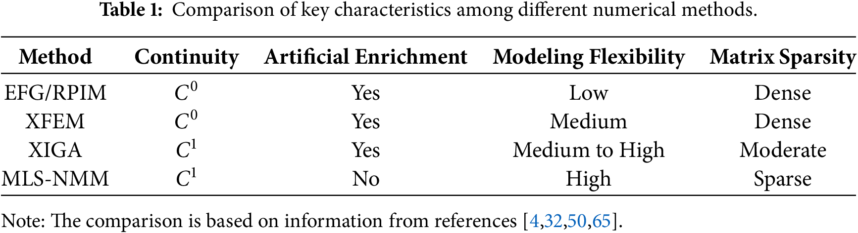
For FGM structural components with complex geometries, numerical modeling has emerged as an efficient and reliable analytical approach. The successful implementation of such computational methods relies critically on sound theoretical frameworks. In the analysis of bending behavior of FGM plates, the two most widely used plate theories are the Kirchhoff–Love theory based on the thin-plate assumption [9,10] and the Reissner-Mindlin theory, which accounts for shear deformation effects [11,12]. Commonly used numerical methods include the finite element method (FEM) [13–16], the element-free Galerkin method (EFG) [17,18], the boundary element method (BEM) [19–22], other meshfree methods [23–26], the coupled finite element and element-free Galerkin method (FE-EFG) [27–29], the extended finite element method (XFEM) [30–32], and extended isogeometric analysis (XIGA) [33–35]. In recent years, the aforementioned numerical methods have been extensively employed in both academic research and engineering analyses to address the bending problems of FGM plates.
Thai et al. [36] established a classical plate theory (CPT) framework based on isogeometric analysis (IGA) to evaluate the bending behavior of FGM plates. Reddy et al. [37] conducted a systematic analysis of the static bending behavior of circular and annular FGM plates under axisymmetric tensile loads using the first-order shear deformation theory (FSDT). Zenkour [38] analyzed the static mechanical behavior of FGM rectangular plates under transverse loading based on a generalized shear deformation theory. Kulkarni et al. [39] developed an improved shear deformation model based on cotangent inverse trigonometric functions and applied it to the bending analysis of FGM plates. Demirhan and Taskin [40] systematically investigated the bending response of porous FGM plates under static loading based on a four-variable plate theory.
The above studies focus primarily on the static bending behavior of intact or porous FGM plates. Meanwhile, the mechanical modeling of plate and shell structures is evolving toward higher-order formulations, material non-uniformity, and multiphysics coupling. In recent years, for shell structures characterized by material gradation, porosity distribution, or orthotropic heterogeneity, higher-order shear deformation theory (HSDT) has been widely employed to accurately capture their mechanical response [41]. Existing studies have systematically investigated the post-buckling behavior of porous shells under non-uniform edge loading [42], the evolution of vibration modes in nonlinear oscillations [43], as well as the influence of spatially varying porosity on natural frequencies [44] and free vibration responses [45]. Although these works mainly address stability or dynamic problems, they consistently demonstrate that material non-uniformity has a pronounced effect on the displacement field and its higher-order derivatives (such as curvature and bending moments). They further indicate that HSDT plays a crucial role in accurately capturing these effects.
For thin plate structures, whether in static bending or dynamic response, the
This requirement becomes particularly prominent in the bending analysis of cracked structures. Knowles and Wang [46] employed the Reissner plate theory accounting for transverse shear deformation to evaluate the stress field distribution at crack tips in thin plates. The results showed that the obtained stress state at the crack tip is in excellent agreement with the predictions of classical plane elasticity theory. Tanaka et al. [47,48] proposed a meshfree numerical framework based on the reproducing kernel particle method for analyzing the moment intensity factors in Mindlin-Reissner plates, and adopted a node-based integration technique within the
However, existing methods still face significant challenges when dealing with complex crack topologies or multiphysics coupling. FEM requires frequent remeshing. XFEM avoids remeshing but still relies on a background mesh and involves complex integration. IGA lacks sufficient flexibility for modeling complex geometries [52,53]. Traditional meshfree methods also suffer from difficulties in imposing boundary conditions and from shape functions that do not possess the Kronecker delta property. Moreover, to ensure accuracy, most meshfree methods (such as EFG and RPIM) require dense node distributions or enlarged influence domains [54–57]. This is especially true when solving fourth-order thin plate problems, where the high continuity requirements lead to many redundant nodes. As a result, the system matrices become highly dense, computational costs increase sharply, and overall efficiency decreases. In contrast, the Numerical Manifold Method (NMM) offers high-order continuity, flexible construction of local approximation spaces, and adaptive meshing features. This makes NMM a more promising numerical framework for high-precision bending analysis of FGM and cracked homogeneous thin plates.
The NMM was proposed by Dr. Shi [58], and its core lay in a dual-cover system composed of mathematical patches and physical patches. This framework enabled a unified treatment of both continuous and discontinuous mechanical problems and exhibited significant advantages in modeling cracks, material interfaces, and strongly singular boundary conditions. In recent years, NMM was extensively investigated and applied in a wide range of fields [59–62]. Zheng and Xu [63] proposed modeling strategies for curved crack paths together with refined integration schemes in the crack tip region, which significantly improved the computational accuracy of NMM. Guo and Zheng [64] further extended high-order NMM to shell structure analysis and, based on the Naghdi shell model, effectively suppressed membrane locking and shear locking in thin-shell problems. To reduce the dependence on mesh generation and improve preprocessing efficiency, Zheng et al. [65] developed the meshfree numerical manifold method (MLS-NMM), in which moving least squares (MLS) approximations were employed as weight functions to replace conventional shape functions. This approach not only enhanced interpolation accuracy and alleviated shear locking, but also effectively avoided linear dependence issues in high-order models, demonstrating excellent numerical stability and accuracy in thin plate bending analyses [66].
On this basis, the MLS-NMM framework proposed in this study deeply integrates MLS approximation with the dual-cover mechanism of NMM, and for the first time realizes a unified enrichment-free treatment that simultaneously satisfies
(1) Simultaneous satisfaction of
(2) Accurate representation of crack-tip singularities through locally enhanced basis functions. In the singular physical patches generated by crack-induced cutting, displacement singular bases of order
(3) Seamless integration of displacement discontinuities and high-order continuity. Benefiting from the automatic cutting mechanism of the dual-cover system, displacement jumps across cracks are naturally represented by the independent degrees of freedom associated with different physical patches, while
To the authors’ best knowledge, this study is the first to apply MLS-NMM within a
The organization of this paper is as follows: Section 2 introduces the fundamental framework of plate theory and derives the weak form corresponding to bending problems of FGM plates. Section 3 systematically presents the basic theory of MLS-NMM, including the construction of shape functions, the implementation mechanism of the dual coverage system, and special treatments for the crack tip region in cracked plates. Section 4 provides the discrete governing equations and the numerical implementation procedure for plate-bending analysis within the proposed framework. Section 5 derives detailed formulas for calculating stress intensity factors (SIF) to evaluate the mechanical response near crack tips. Section 6 validates the accuracy, stability, and applicability of the proposed MLS-NMM framework by comparing numerical results from a series of examples with reference solutions reported in the literature for bending of FGM plates and fracture-related problems in cracked homogeneous plates.
2 Governing Equation and Weak Form for Bending of FGM Plates
The physical properties of FGM plates vary continuously through the thickness, with the elastic modulus typically described by a power-law function. Based on classical plate theory and neglecting transverse shear deformation, in-plane displacements are characterized by the mid-surface deflection and its spatial derivatives. Accordingly, the geometric relationships between strain and deflection, as well as the corresponding stress-strain constitutive relations, are established. Furthermore, the weak form governing equations for bending problems of FGM plates are constructed using the Galerkin variational method. Boundary conditions such as simply supported and clamped edges are numerically enforced through the penalty method, enabling effective and strong imposition of constraints.
2.1 Functionally Graded Materials
Geometric configuration and notation of the FGM plate are shown in Fig. 1. Here,
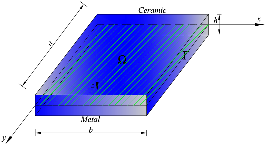
Figure 1: Geometric configuration of an FGM plate.
Assuming the bottom surface of the plate is made of pure metal and the top surface is made of pure ceramic, the material composition transitions continuously along the thickness direction. The volume fraction of the ceramic phase is defined as:
The volume fraction of the metal phase is given by
When
When
When
The Young’s modulus
here,
This study considers only the bending behavior under purely mechanical loads, completely neglecting thermal effects. However, the employed MLS-NMM framework possesses good structural extensibility and can be further extended in the future to incorporate thermo-mechanical coupling effects, for example, by introducing thermal bending moments caused by temperature fields and gradients in the material’s coefficient of thermal expansion. Such extensions will be addressed in future work.
Variation of ceramic phase volume fraction along the thickness direction under different gradient indices
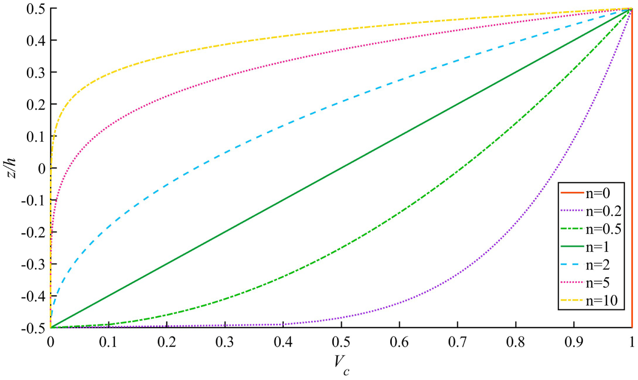
Figure 2: Volume fraction variation along thickness of an FGM plate.
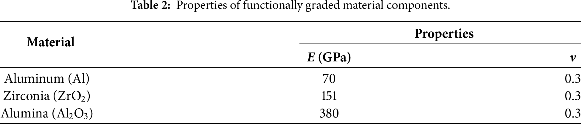
In this study, two types of FGM plates made of Al/ZrO2 and Al/Al2O3 are considered, and their material parameters are listed in Table 2.
2.2 Basic Framework of the Kirchhoff–Love Plate Theory
To analyze the bending response of FGM thin plates under transverse loading and the fracture behavior of cracked homogeneous plates, this study employs the classical Kirchhoff–Love plate theory. This theory is suitable for thin plates whose thickness is much smaller than the in-plane characteristic dimensions and neglects the effects of transverse shear deformation.
In this theory, the three-dimensional displacement field at any point within the plate is fully determined by the transverse deflection
here,
The corresponding linear strain–displacement relations include only bending-induced normal and shear strains, with the nonzero components given by:
By introducing the curvature–twist vector
here,
For FGM plates, the elastic modulus
The bending–twisting moment vector per unit width,
where D is positive symmetric definite, reading
Under the transverse distributed load
The boundary
On the clamped boundary
On the simply supported boundary
On the free boundary
here,
In the subsequent numerical examples, simply supported boundary conditions on all four edges (SSSS) and clamped boundary conditions on all four edges (CCCC) are imposed by setting
2.3 Weak Formulation of FGM Plate Bending Problem
The bending problem of the FGM plate takes the deflection
here, w satisfies the essential boundary conditions, that is,
In the NMM, high interpolation accuracy can be achieved by flexibly placing mathematical covers without strictly aligning them with the plate mid-plane boundary, significantly enhancing geometric adaptability and modeling flexibility. However, this unstructured covering approach poses challenges for imposing essential boundary conditions. To address this, the present study adopts the penalty method to handle boundary constraints, thereby simplifying the numerical implementation. Therefore, Eq. (15) can be expressed as:
where
In all bending analysis examples presented in this paper, the penalty parameter is uniformly set to
3 Basic Principles of MLS-NMM and Local Approximations for Crack Tips
Unlike the traditional finite element (FE-based) NMM, which uses meshes to construct mathematical covers [68], Zheng et al. [65] proposed a mesh-free strategy for constructing mathematical covers: by introducing the influence domain of MLS approximation nodes as the basic unit of mathematical covers, and directly using the MLS shape functions as weight functions on the mathematical patches. This method eliminates dependence on meshes and significantly enhances modeling flexibility and geometric adaptability. The MLS approximation offers advantages such as high approximation accuracy, good boundary treatment capability, and a simple formulation [69], making it particularly suitable for numerical simulations involving irregular node distributions and complex domains. Moreover, this method belongs to the class of partition-of-unity methods, which allows the introduction of enrichment functions—capable of capturing local solution features—into the physical patches. This effectively enhances the representational capacity of the approximation space, significantly improving both numerical accuracy and geometric adaptability.
3.1 Crack Treatment under Dual Coverage
Discrete points, also known as mathematical nodes, are distributed over the mid-plane
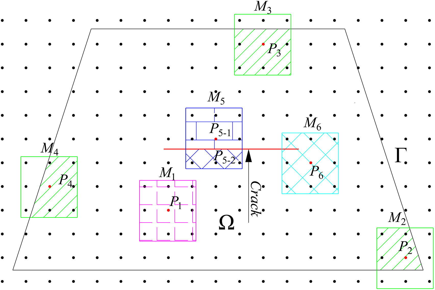
Figure 3: MLS node distribution for a cracked plate.
To accurately capture geometric and material discontinuities in the problem domain
This process automatically adapts to various geometric scenarios (see Fig. 3):
(i) If
All physical patches together form the physical covering set that precisely covers
In summary, the MLS-NMM combined with the cutting strategy offers the following advantages over standard XFEM or XIGA methods when simulating plates with crack-induced discontinuities:
(1) Simplified modeling: Based on meshfree mathematical covering, it eliminates the need for geometry-conforming mesh generation. Physical patches can directly span discontinuities such as cracks, naturally capturing displacement jumps and singularities.
(2) High efficiency and accuracy: It achieves high-precision approximation of defects like cracks without local mesh refinement or remeshing, balancing computational efficiency and numerical accuracy.
(3) Strong adaptability: It can uniformly and efficiently handle various geometric discontinuities without algorithm adjustments or additional preprocessing for different defect types [70,71].
The MLS shape function
where x denotes the position vector on the mathematical patch, used to define the spatial coordinates of the local approximation function. The set of weight functions
For solving the fourth-order partial differential equations of plates, the
here,
The linear basis
The secondary basis
And the cubic basis
here, to satisfy the
Although cubic bases theoretically offer higher smoothness, preliminary tests showed that under the same node distribution, they significantly increase the condition number of matrix
The function
here,
In general, all MLS weight functions
In this study, the support of
here,
where z represents either
All mathematical patches are cut by the problem domain boundaries, holes, and cracks to form physical patches. The physical patch
After assigning a unified numbering to all physical patches, a local approximation of the plate deflection
here,
and a coefficient vector
For a non-singular physical patch
In contrast, for singular physical patches containing crack tips, enhanced basis functions incorporating singular terms are introduced to more accurately capture stress concentration behavior. This can be expressed as:
Specifically, a local
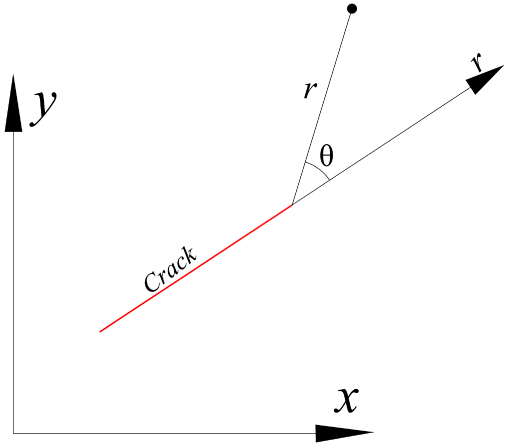
Figure 4: Crack-tip coordinates in local and global coordinate systems.
In the Kirchhoff–Love thin-plate theory, the displacement field (i.e., the deflection) near a crack tip exhibits the characteristic
By performing a weighted summation of the local approximation functions over all physical patches and utilizing the partition of unity property, a globally continuous approximate displacement field can be constructed as follows:
Substituting Eq. (26) into Eq. (29) yields the global approximate displacement field as follows:
where
while each subvector
The shape function matrix
where
Therefore, in the NMM, the mathematical cover is automatically cut by discontinuous interfaces (such as cracks or boundaries), generating multiple physical patches. Each physical patch independently carries a set of nodal degrees of freedom and serves as a computational unit for local approximation. This patch-based structure allows discontinuities in the displacement field across interfaces to be naturally represented, thereby efficiently capturing and simulating various discontinuous features in materials or structures through Eq. (30).
Thanks to its intrinsic piecewise approximation mechanism, the NMM can accurately model displacement jumps and singular behaviors without introducing additional enrichment functions (such as the Heaviside function used in XFEM to describe strong discontinuities) [73]. This significantly simplifies the modeling process of discontinuous problems while enhancing computational robustness and implementation efficiency.
4 MLS-NMM Discretization Formulation for Plate Bending
This section performs bending analyses of FGM plates and cracked homogeneous plates within the MLS-NMM framework, based on classical thin-plate theory. The objective is to validate the effectiveness and applicability of the proposed method for these two categories of bending problems.
According to thin plate theory, neglecting transverse shear deformation, the displacement field is described by the mid-surface deflection
here,
The submatrix
where the strain-displacement matrix
where
The i-th component of the equivalent nodal load vector
here,
In particular, within MLS-NMM, when a physical patch is intersected by a crack, its integration domain
5 Calculation of Stress Intensity Factor (SIF)
In this section, the stress intensity factor is calculated within the MLS-NMM framework based on thin plate theory. The objective is to validate the applicability of the stress intensity factor in the bending analysis of cracked plates.
5.1 Asymptotic Displacement near Crack Tip and Fracture Modes
In thin plate theory, two fracture modes exist depending on the type of loading: symmetric bending mode
where
In polar coordinates
where z is the out-of-plane component of the current coordinate vector.
5.2 J-Integral and Interaction Integral
The classical
where
In the present MLS-NMM implementation, we tested multiple integration domains of different shapes and sizes. The results show that the variation of the computed
Based on thin plate theory, under mixed-mode loading conditions, the relationship between the
where
To separate
After expansion and rearrangement, it can be expressed as:
where:
and the interaction integral
Combining with Eq. (43), the
From this, the relationship between the interaction integral
The auxiliary fields serve to provide analytical reference solutions with known modal characteristics. By coupling these with the actual fields, the intensity factors of specific fracture modes can be extracted. In the numerical implementation, these auxiliary states are directly constructed using Eqs. (39)–(41), where the asymptotic displacement and stress fields corresponding to a unit symmetric mode
Finally, the stress intensity factors in the actual state can be obtained by the following expressions:
and
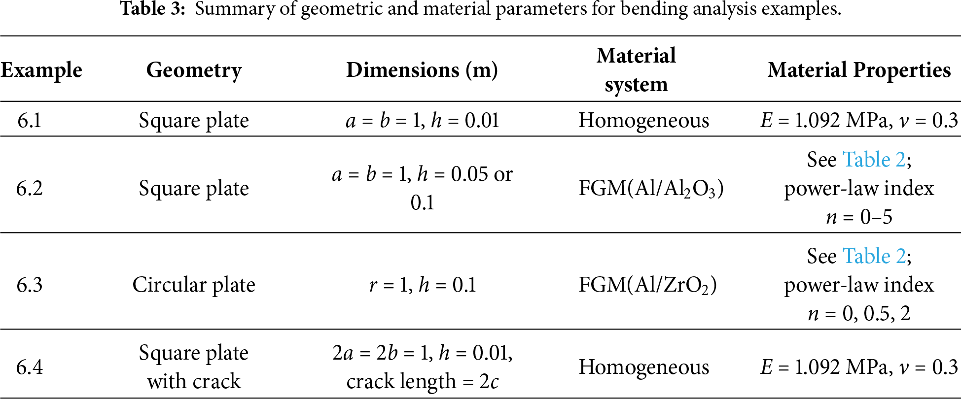
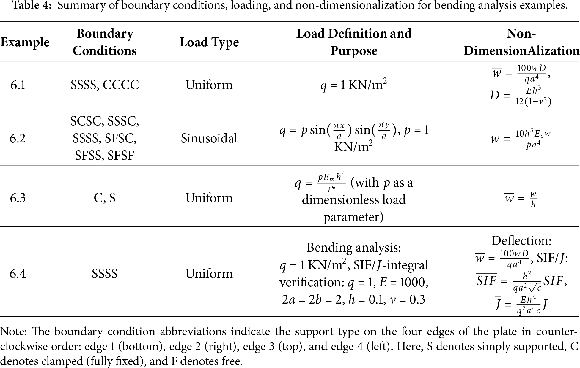
To systematically verify the accuracy and applicability of MLS-NMM in simulating the bending behavior of intact FGM thin plates and cracked homogeneous thin plates, this section presents four typical numerical examples: (i) convergence analysis of homogeneous square plates; (ii) bending response of Al/Al2O3 FGM square plates; (iii) bending behavior of Al/ZrO2 FGM circular plates; (iv) fracture mechanics analysis of homogeneous square plates with central cracks. All examples explicitly specify geometric dimensions, material properties, boundary conditions, loading types, and nondimensionalization schemes.
In particular, Example 6.4 employs two independent yet geometrically similar parameter systems: one defined in physical units for the analysis of the actual bending stress field, and the other formulated as a dimensionless reference model dedicated to the validation of the SIF and the
For crack-free FGM plates, the material properties vary continuously through the thickness direction, ensuring good structural integrity. Conducting bending analysis helps elucidate the influence of material heterogeneity, geometric dimensions, and boundary conditions on deflection distributions and stiffness characteristics, while also validating the accuracy of the MLS-NMM in capturing smooth graded fields and continuous deformation responses.
When cracks or other defects are present in the plate, local stiffness degradation occurs, leading to stress field redistribution. This alters the deformation pattern, increases deflection, and reduces load-carrying capacity. Furthermore, the location and length of the crack significantly influence the complexity of the bending response, potentially triggering local instability or structural failure.
Therefore, comparing the bending behavior of intact and cracked plates not only helps assess the extent to which defects influence structural performance but also provides a basis for validating the applicability of the MLS-NMM in modeling both undamaged and damaged structures. In this section, several numerical examples are presented to demonstrate the bending response of isotropic and FGM plates. Model validation is performed through representative case studies to evaluate the convergence and computational reliability of the MLS-NMM.
To evaluate convergence and accuracy, the relative error of the nondimensional central deflection is defined as:
where
To verify the convergence and accuracy of MLS-NMM in classical thin plate bending problems, numerical simulations are first conducted on homogeneous square plates. Two typical boundary conditions—simply supported (SSSS) and clamped (CCCC)—are considered. The central deflection under uniformly distributed load is used as the evaluation metric. Relevant geometric, material, and nondimensionalization parameters are detailed in Tables 3 and 4.
Under uniformly distributed load, for a homogeneous square plate with an aspect ratio of a/h = 100, the nondimensional central deflection computed by MLS-NMM using different numbers of mathematical nodes (100, 144, 196, 324, and 676) is listed in Table 5. The results from Ref. [78] are adopted as the reference exact solution for comparative analysis. It is observed that the MLS-NMM solutions converge as the number of nodes increases, and when the node count reaches 676, the numerical results achieve excellent agreement with the reference solutions.
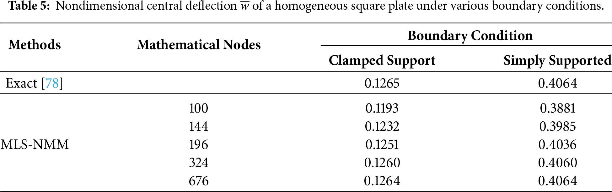
Fig. 5 shows the relative error of the dimensionless central deflection for a homogeneous square plate as a function of the number of mathematical nodes under different boundary conditions. It can be observed that, as the number of mathematical nodes increases, the numerical solution obtained by the MLS-NMM gradually stabilizes and converges toward the exact solution. When the number of nodes reaches 676, the relative error is minimized, and the numerical results are in excellent agreement with the exact solution. This demonstrates that the MLS-NMM exhibits high numerical accuracy and good convergence performance in solving thin plate bending problems, and is capable of effectively capturing the structural mechanical responses under various boundary conditions, such as simply supported and clamped edges.
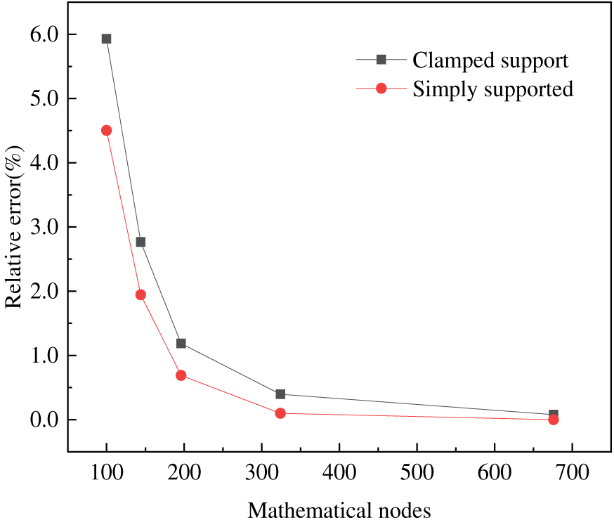
Figure 5: Convergence analysis of a homogeneous square plate under various boundary conditions using MLS-NMM.
Figs. 6 and 7 illustrate the dimensionless deflection distributions of a homogeneous square plate calculated using the MLS-NMM under different boundary conditions. It can be observed that the deformation magnitude under simply supported (SSSS) conditions is significantly larger than that under clamped (CCCC) conditions, indicating that stronger boundary constraints effectively suppress the deformation, highlighting the significant influence of boundary stiffness on the overall bending response. The maximum deflection occurs at the center of the plate, with the dimensionless deflection showing a symmetric parabolic distribution about the center, decreasing gradually from the center toward the edges and approaching zero at the boundaries, consistent with the imposed boundary constraints.
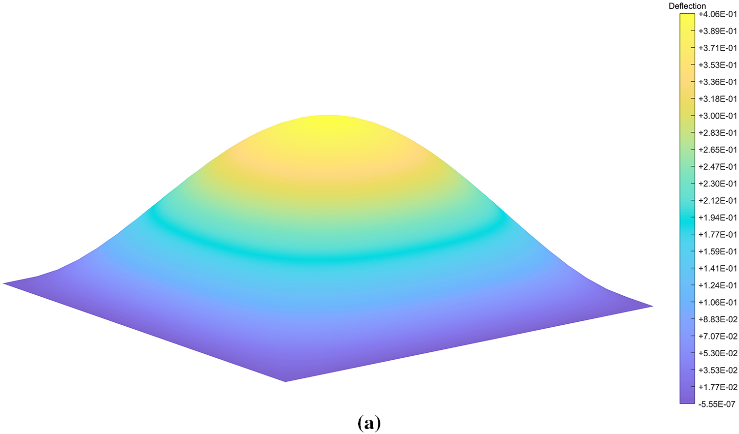
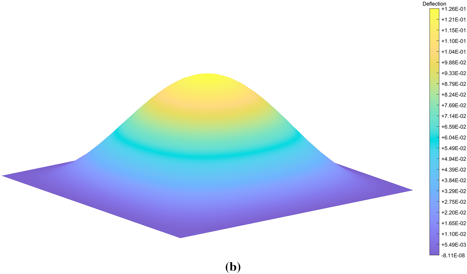
Figure 6: Nondimensional deflection contours of a homogeneous square plate: (a) simply supported (SSSS); (b) clamped (CCCC).
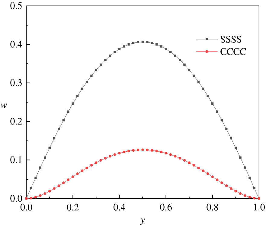
Figure 7: Nondimensional deflection
6.2 Bending Analysis of FGM Square Plate
To further assess the capability of MLS-NMM in handling nonhomogeneous material fields, this section conducts bending analysis of an Al/Al2O3 FGM square plate. The plate is subjected to sinusoidally distributed load and six different combinations of boundary conditions are considered to comprehensively evaluate the method’s applicability under complex support scenarios. Detailed modeling parameters are listed in Tables 3 and 4.
Within the MLS-NMM framework, mathematical nodes are uniformly distributed for the FGM square plate, with the node distribution shown in Fig. 8a and the Gauss integration mesh depicted in Fig. 8b.
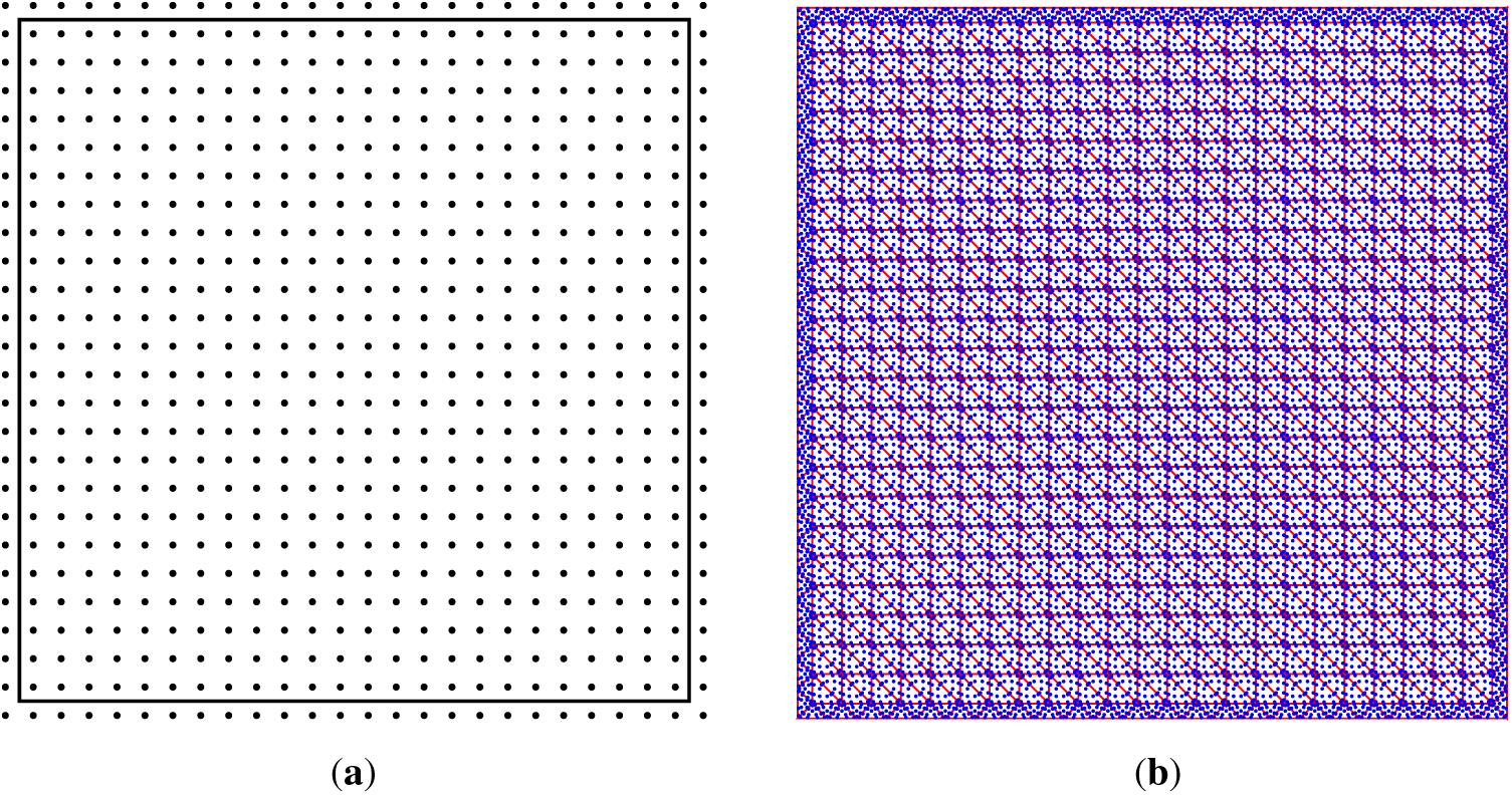
Figure 8: FGM square plate: (a) distribution of mathematical nodes, (b) Gauss integration mesh.
Fig. 9 illustrates the three-dimensional distribution of dimensionless deflection for an FGM square plate under sinusoidal loading across six typical boundary conditions. It can be observed that, regardless of the loading scenario, the deflection patterns conform to the fundamental mechanical behavior of thin plate bending. Additionally, different boundary constraints significantly influence both the deformation mode and its magnitude, clearly demonstrating the critical role of boundary conditions in governing the bending response of FGM plates.
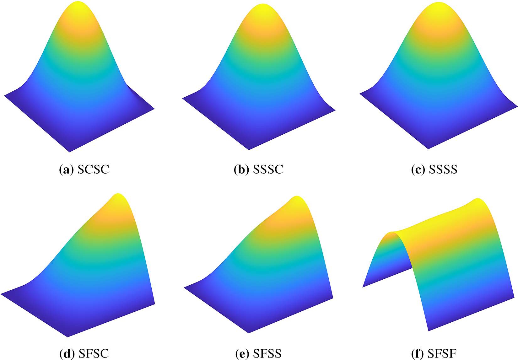
Figure 9: Nondimensional deflection contours of a square FGM plate under various boundary conditions. (a) SCSC. (b) SSSC. (c) SSSS. (d) SFSC. (e) SFSS. (f) SFSF.
The bending analyses for different gradient indices
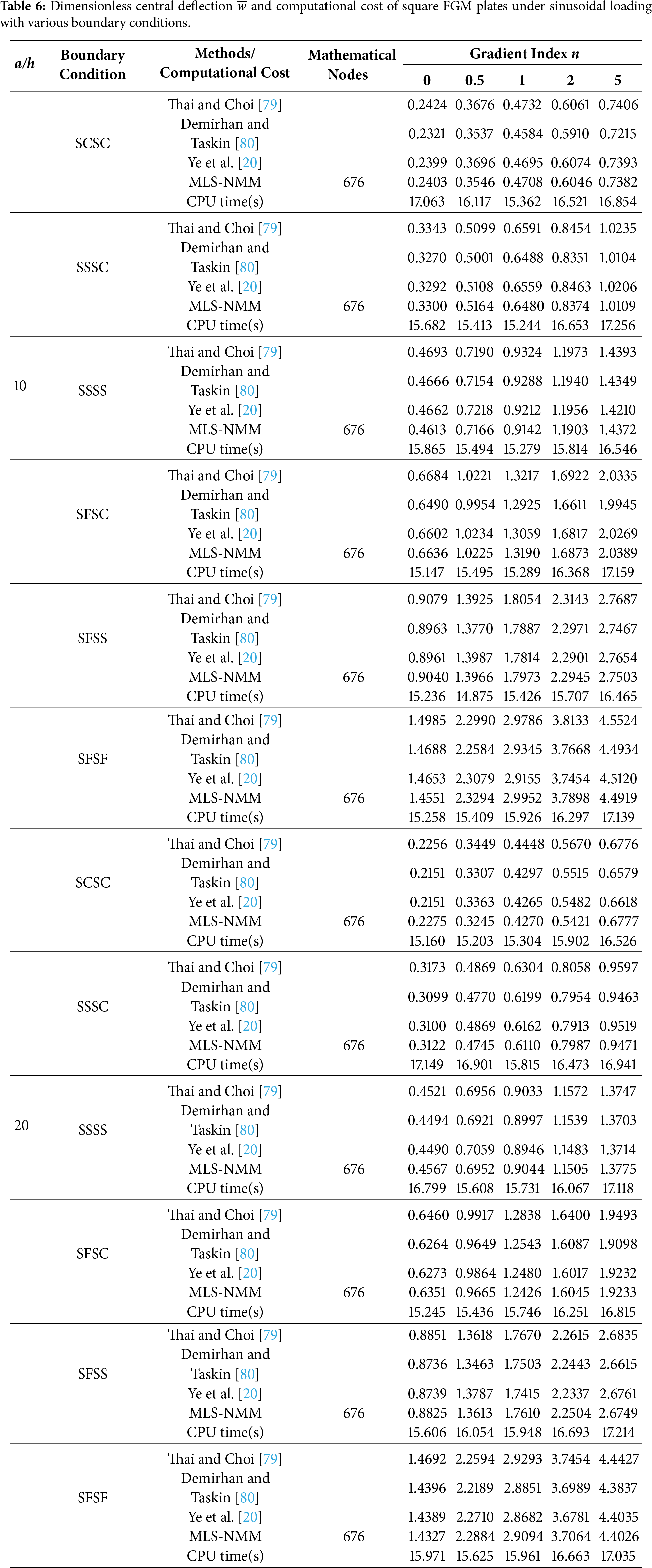
Under sinusoidal loading, Table 6 presents the dimensionless central deflections of an FGM square plate under various boundary conditions, computed using the MLS-NMM. A comparative analysis demonstrates good agreement between the present numerical results and the reference solutions, verifying the accuracy and reliability of the MLS-NMM in solving bending problems of FGM plates.
Further analysis shows that the nondimensionalized center deflection significantly depends on both material and geometric parameters: for a fixed gradient index
To quantify the effect of the gradient index
As shown in Fig. 10, the nondimensional center deflection
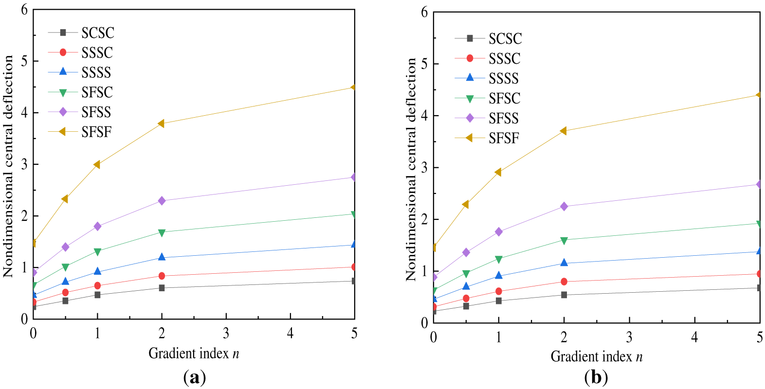
Figure 10: Dimensionless central deflection
Moreover, under identical geometric and material parameters, the boundary constraints have a significant influence on the deflection response. Among the cases considered, the SCSC condition (simply supported on two opposite edges and clamped on the other two) yields the smallest dimensionless central deflection, indicating the highest constraint stiffness and the most effective deformation suppression. In contrast, the SFSF condition (simply supported on two opposite edges and free on the other two) results in the largest deflection, reflecting the lowest support stiffness and a greater susceptibility to bending deformation.
Fig. 11 illustrates the distribution of dimensionless deflection along the two central cross-sectional lines (x = 0.5 m and y = 0.5 m) for an FGM square plate under sinusoidal loading, with a side-to-thickness ratio a/h = 20 and a gradient index n = 0.5. The figure clearly reveals the influence of different boundary conditions on the spatial distribution of the deformation field within the plate.
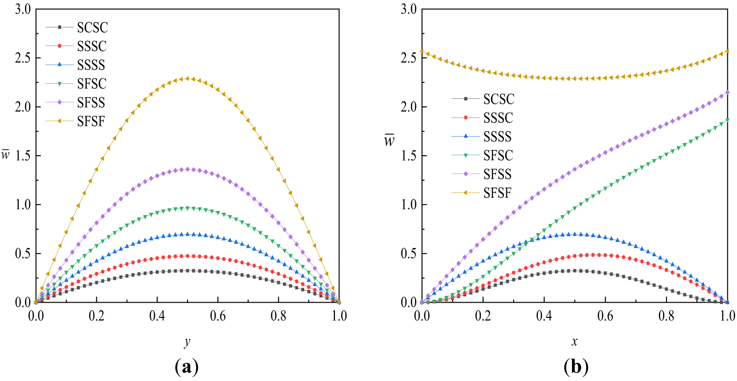
Figure 11: Nondimensional deflection
As shown in Fig. 11a, the dimensionless deflection curves along the cross-sectional line at x = 0.5 m (i.e., the transverse section) exhibit excellent symmetry under all boundary conditions, with the maximum deflection occurring at the geometric center of the plate (y = 0.5 m). This indicates that the deformation in this direction is less influenced by the combined effects of symmetric loading and boundary constraints, leading to a structural response that is concentrated around the central region.
In contrast, the deflection distribution along the y = 0.5 m section (longitudinal section) in Fig. 11b exhibits significant asymmetry, reflecting the asymmetric constraint effects of boundary conditions in different directions. Specifically, under SCSC and SSSS boundary conditions, the deflection curves remain symmetric with peaks at the center; under SSSC condition, due to one clamped edge and one simply supported edge, the maximum deflection shifts toward the simply supported side and occurs near it; for SFSC and SFSS conditions, with one free edge, the maximum deflection clearly appears at the midpoint of that free edge, reflecting intensified local deformation caused by released constraints; and for the SFSF condition with two pairs of free edges, the maximum deflections occur simultaneously near the midpoints of both free edges, forming a dual-peak distribution, further highlighting the weakening effect of free edges on structural stiffness.
6.3 Bending Analysis of FGM Circular Plate
To extend the application of the method to non-rectangular domains and different FGM systems, this section investigates the bending response of an Al/ZrO2 FGM circular plate under uniform loading. Both simply supported (S) and clamped (C) boundary conditions are considered. Results are presented using a nondimensional load parameter based on the metal’s modulus. Detailed parameter settings are listed in Tables 3 and 4.
In the MLS-NMM framework, mathematical nodes are uniformly distributed for the FGM circular plate. The node distribution is illustrated in Fig. 12a, and the corresponding Gauss integration mesh is depicted in Fig. 12b.
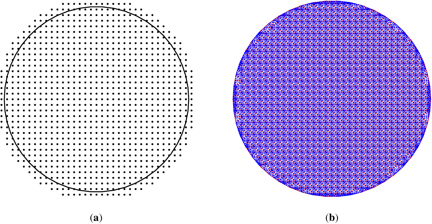
Figure 12: FGM circular plate: (a) distribution of mathematical nodes, (b) Gauss integration mesh.
Fig. 13 presents the nondimensional deflection profiles of the FGM circular plate under different boundary conditions, computed using MLS-NMM. The results show that, under both boundary conditions, the plate deformation exhibits an axisymmetric, bowl-shaped pattern. The maximum deflection occurs at the plate center and gradually decreases toward the edges. Compared to the clamped boundary, the plate under simply supported boundary exhibits larger overall deformation.
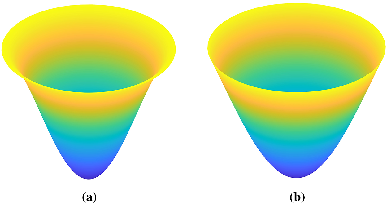
Figure 13: Nondimensional deflection contours of an FGM circular plate: (a) clamped boundary; (b) simply supported boundary.
Under uniform distributed loading, Tables 7 and 8 present the nondimensional center deflections of clamped and simply supported FGM circular plates, respectively, for different gradient indices and applied loads p. The MLS-NMM results show excellent agreement with references [81,82], fully validating the reliability and accuracy of the method in handling varying material gradient distributions and load intensities.
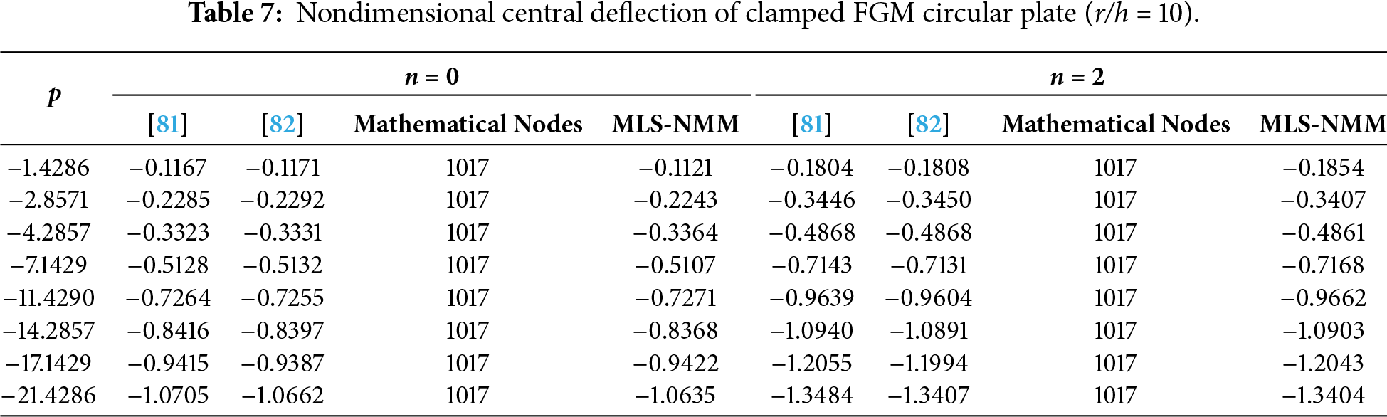
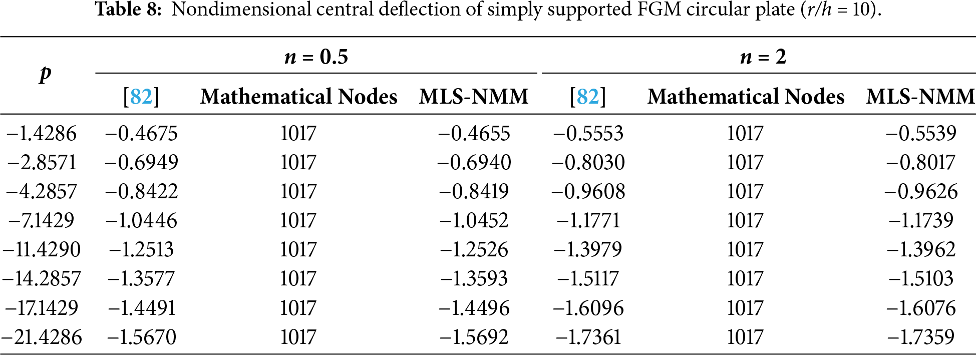
Further analysis indicates that boundary constraints play a decisive role in the deformation behavior of the plate: under the same loading conditions, the dimensionless central deflection of simply supported plates is consistently and significantly larger than that of clamped plates. For instance, at
Overall, as the gradient index
As shown in Fig. 14, under uniform distributed load, the nondimensional center deflection
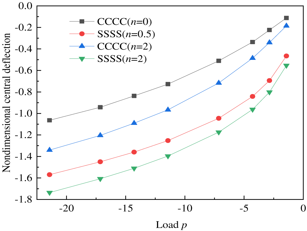
Figure 14: Dimensionless central deflection
In addition, under the same boundary conditions, as the gradient index
6.4 Bending Analysis of Square Plate with Center Crack
To validate the effectiveness of MLS-NMM in handling geometric discontinuities such as cracks, this section conducts bending simulations on a homogeneous square plate with a central crack. The plate is simply supported and subjected to a uniformly distributed load. Besides the deflection response, the fracture mechanics behavior near the crack tip is also examined.
It should be emphasized that this example employs two distinct parameter systems to serve different analysis objectives. Specifically, the bending stress field analysis adopts parameters with physical dimensions in order to obtain realistic stress distributions, whereas the calculations of the SIF and the
Fig. 15a illustrates the distribution of mathematical nodes and the configuration of the horizontal central crack (c/a = 0.6) in the homogeneous square plate, while Fig. 15b displays the corresponding Gauss integration mesh.
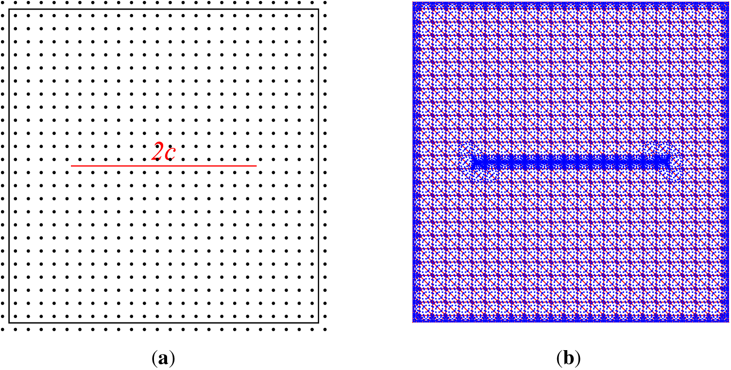
Figure 15: Square plate with a horizontal center crack: (a) mathematical nodes and crack configuration; (b) Gauss integration mesh.
To quantify the impact of crack defects on structural stiffness, the maximum (center) deflection of the cracked plate is compared with that of the intact plate under the same load and boundary conditions. As shown in Table 9, the nondimensional center deflection increases significantly with the crack length ratio
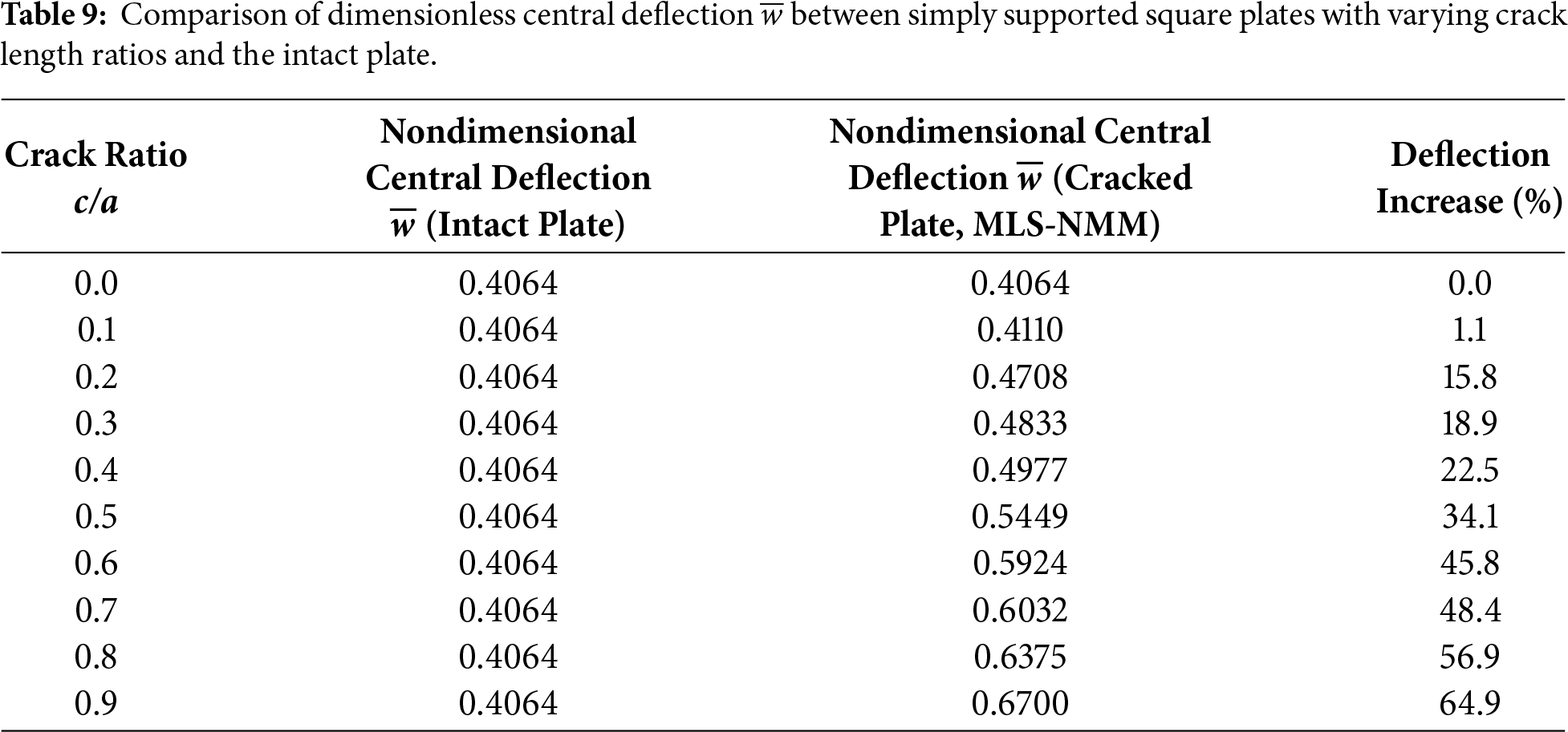
Under the same simply supported boundary conditions (SSSS) and geometric settings, a comparative analysis between Tables 6 and 9 show that the nondimensional center deflection is significantly more sensitive to the gradient index
The convergence of the dimensionless stress intensity factor (
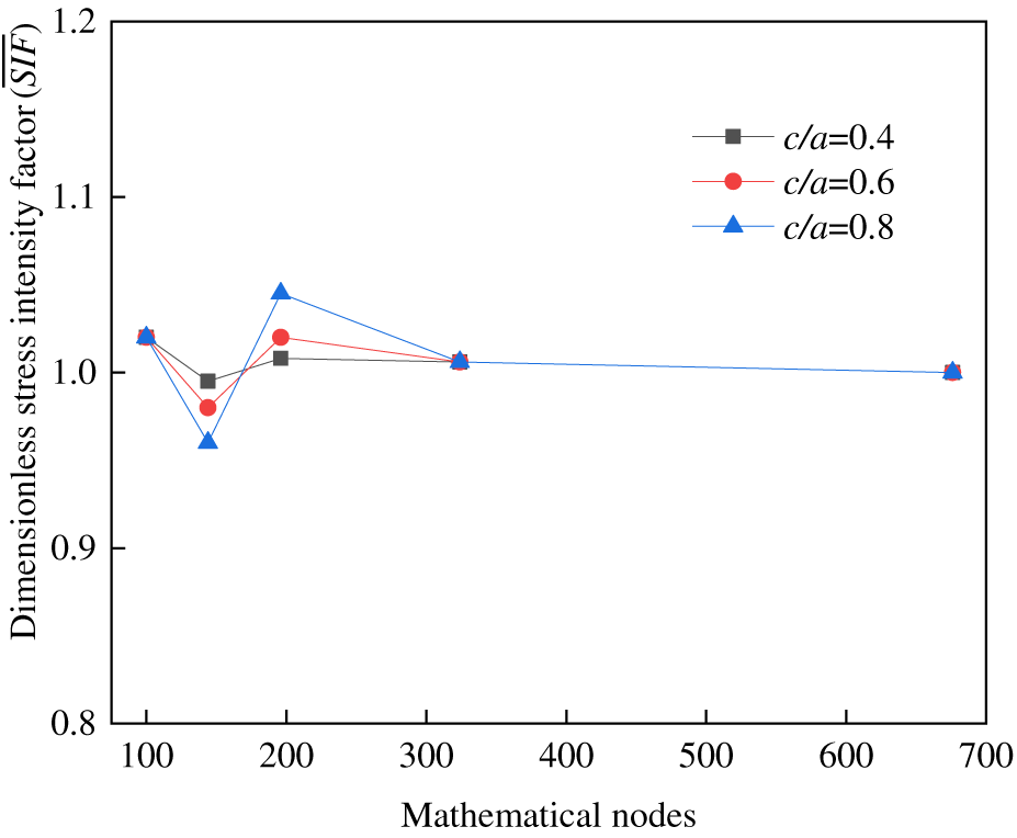
Figure 16: Convergence of the dimensionless stress intensity factor (
Under uniform loading, Table 10 presents the dimensionless
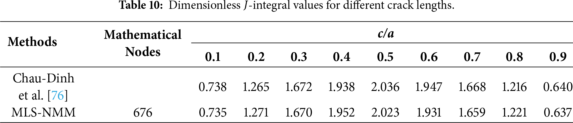
Fig. 17 presents the bending response of a homogeneous square plate with a central crack under a uniformly distributed load, as computed by MLS-NMM. Fig. 17a shows the deflection contour, indicating that the maximum downward deflection occurs in the central region and forms a symmetric bowl-shaped profile; the deflection gradually decreases from the center toward the edges and approaches zero along the simply supported boundaries. Due to the presence of the crack, the deformation is significantly amplified in the vicinity of the crack tips, exhibiting a pronounced feature of locally intensified indentation. Fig. 17b–d depicts the distributions of the normal stress
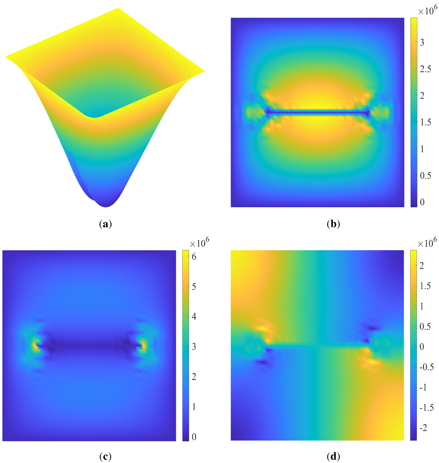
Figure 17: Bending response of a homogeneous square plate with a central crack (bottom surface): (a) Deflection distribution, (b) normal stress in the x direction
Overall, these results demonstrate that the presence of the crack not only alters the global deformation mode of the plate but also induces strong localized stress concentrations, thereby confirming the capability of the proposed numerical method to accurately capture key features of fracture mechanics problems.
As shown in Fig. 18, under uniform loading, the dimensionless
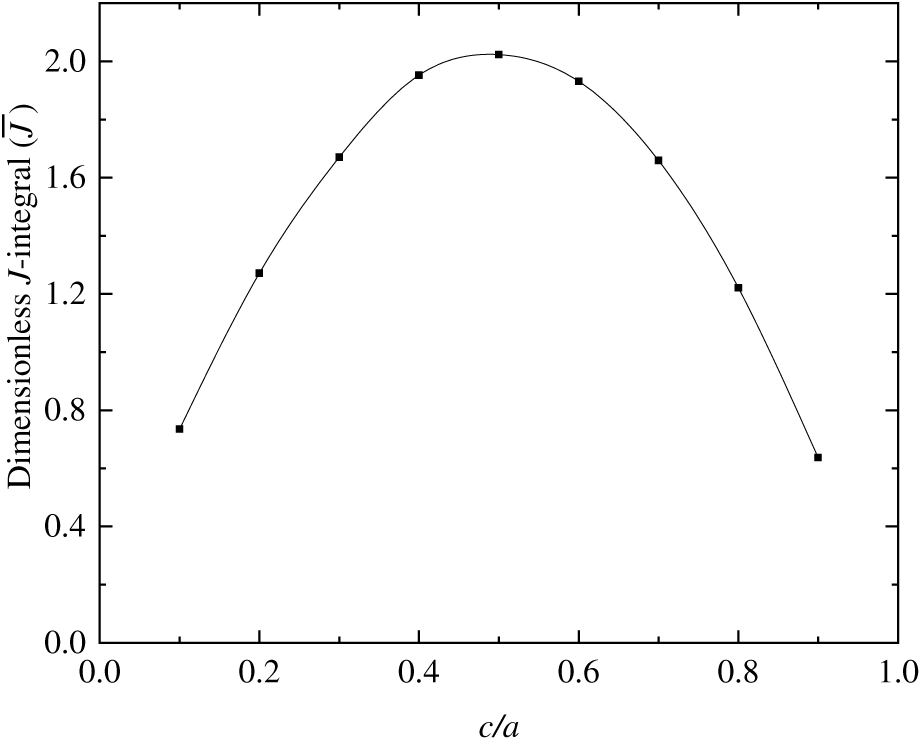
Figure 18: Variation of the dimensionless
This study proposes an MLS-NMM with
(1) High accuracy and convergence: MLS-NMM naturally satisfies the high-order continuity requirements of the Kirchhoff–Love theory. Key quantities such as the non-dimensional deflection and dimensionless
(2) Gradient index influences stiffness: Increasing the gradient index leads to a significant rise in the center deflection of the FGM plate, reflecting structural softening due to the reduced ceramic phase fraction.
(3) Boundary conditions dominate deformation: Strong constraints suppress deformation, while weak constraints significantly amplify deflection; the type of boundary condition decisively affects the response magnitude and distribution.
(4) Defects weaken bending performance: Cracks cause local stiffness degradation, markedly increasing overall deflection, highlighting the adverse impact of geometric defects on mechanical response.
(5) Unified treatment of complex defects: By integrating Williams’ asymptotic singular physical patches with the NMM double coverage mechanism, displacement discontinuities and stress singularities of cracks are accurately captured without the need for additional enrichment.
This framework focuses on the static bending and fracture analysis of FGM and defective plates, featuring strong extensibility. It can be further extended to sandwich plates, fiber-reinforced composite plates, and dynamic response problems, providing an effective numerical tool for the multi-scale, multi-physics coupled analysis of complex structures.
It should be noted that the current model is based on the classical thin-plate theory and neglects transverse shear deformation, making it mainly suitable for thin plates with large aspect ratios. When extended to three-dimensional problems, geometric cutting of physical patches and high-accuracy numerical integration still pose challenges. Nevertheless, the method shows promising potential in thermo-mechanical coupling and dynamic fracture problems, and related research is actively underway.
Acknowledgement: None.
Funding Statement: This study is supported by Beijing Natural Science Foundation(L233025).
Author Contributions: Shouyang Huang: Conceptualization, Investigation, Software, Writing-original draft, Formal analysis, Writing–review & editing, Visualization, Data curation, Validation. Hong Zheng: Conceptualization, Funding acquisition, Methodology, Writing–review & editing, Project administration. Xuguang Yu: Writing–review & editing, Validation. Ziheng Li: Data curation. Zhiwei Pan: Supervision. All authors reviewed and approved the final version of the manuscript.
Availability of Data and Materials: Data sharing not applicable to this article as no datasets were generated or analyzed during the current study.
Ethics Approval: Not applicable.
Conflicts of Interest: The authors declare no conflicts of interest.
References
1. Fukui Y, Yamanaka N. Elastic analysis for thick-walled tubes of functionally graded material subjected to internal pressure. JSME Int J Ser 1 Solid Mech Strength Mater. 1992;35(4):379–85. doi:10.1299/jsmea1988.35.4_379. [Google Scholar] [CrossRef]
2. Obata Y, Noda N. Optimum material design for functionally gradient material plate. Arch Appl Mech. 1996;66(8):581–9. doi:10.1007/BF00808146. [Google Scholar] [CrossRef]
3. Bui TQ, Van Do T, Ton LHT, Doan DH, Tanaka S, Pham DT, et al. On the high temperature mechanical behaviors analysis of heated functionally graded plates using FEM and a new third-order shear deformation plate theory. Compos Part B Eng. 2016;92:218–41. doi:10.1016/j.compositesb.2016.02.048. [Google Scholar] [CrossRef]
4. Liew KM, Zhao X, Ferreira AJM. A review of meshless methods for laminated and functionally graded plates and shells. Compos Struct. 2011;93(8):2031–41. doi:10.1016/j.compstruct.2011.02.018. [Google Scholar] [CrossRef]
5. Van Vinh P, Van Chinh N, Tounsi A. Static bending and buckling analysis of bi-directional functionally graded porous plates using an improved first-order shear deformation theory and FEM. Eur J Mech A/solids. 2022;96:104743. doi:10.1016/j.euromechsol.2022.104743. [Google Scholar] [CrossRef]
6. Sun X, Gao R, Zhang Y. Spectral stochastic isogeometric analysis of bending and free vibration of porous functionally graded plates. Appl Math Model. 2023;116(2):711–34. doi:10.1016/j.apm.2022.12.017. [Google Scholar] [CrossRef]
7. Hachemi H, Bousahla AA, Kaci A, Bourada F, Tounsi A, Benrahou KH, et al. Bending analysis of functionally graded plates using a new refined quasi-3D shear deformation theory and the concept of the neutral surface position. Steel Compos Struct. 2021;39(1):51–64. [Google Scholar]
8. Hadji L, Bernard F, Madan R, Alnujaie A, Ghazwani MH. Bending and buckling of porous multidirectional functionality graded sandwich plate. Struct Eng Mech. 2023;85(2):233–46. [Google Scholar]
9. Chi SH, Chung YL. Mechanical behavior of functionally graded material plates under transverse load: part I: analysis. Int J Solids Struct. 2006;43(13):3657–74. doi:10.1016/j.ijsolstr.2005.04.011. [Google Scholar] [CrossRef]
10. Chi SH, Chung YL. Mechanical behavior of functionally graded material plates under transverse load: part II: numerical results. Int J Solids Struct. 2006;43(13):3675–91. doi:10.1016/j.ijsolstr.2005.04.010. [Google Scholar] [CrossRef]
11. Della Croce L, Venini P. Finite elements for functionally graded Reissner-Mindlin plates. Comput Meth Appl Mech Eng. 2004;193(9–11):705–25. doi:10.1016/j.cma.2003.09.014. [Google Scholar] [CrossRef]
12. Bayat M, Sahari BB, Saleem M, Ali A, Wong SV. Bending analysis of a functionally graded rotating disk based on the first order shear deformation theory. Appl Math Model. 2009;33(11):4215–30. doi:10.1016/j.apm.2009.03.001. [Google Scholar] [CrossRef]
13. Sosa HA, Eischen JW. Computation of stress intensity factors for plate bending via a path-independent integral. Eng Fract Mech. 1986;25(4):451–62. doi:10.1016/0013-7944(86)90259-6. [Google Scholar] [CrossRef]
14. Huang M, Long Y. Calculation of stress intensity factors of cracked reissner plates by the sub-region mixed finite element method. Comput Struct. 1988;30(4):837–40. doi:10.1016/0045-7949(88)90113-7. [Google Scholar] [CrossRef]
15. Su RKL, Leung AYT. Mixed mode cracks in Reissner plates. Int J Fract. 2001;107(3):235–57. doi:10.1023/A:1007652028645. [Google Scholar] [CrossRef]
16. Benounas S, Belarbi MO, Van VP, Daikh AA. Precise analysis of the static bending response of functionally graded doubly curved shallow shells via an improved finite element shear model. Eng Struct. 2024;319(T152):118829. doi:10.1016/j.engstruct.2024.118829. [Google Scholar] [CrossRef]
17. Belytschko T, Gu L, Lu YY. Fracture and crack growth by element free Galerkin methods. Modelling Simul Mater Sci Eng. 1994;2(3A):519–34. doi:10.1088/0965-0393/2/3a/007. [Google Scholar] [CrossRef]
18. Belytschko T, Lu YY, Gu L. Crack propagation by element-free Galerkin methods. Eng Fract Mech. 1995;51(2):295–315. doi:10.1016/0013-7944(94)00153-9. [Google Scholar] [CrossRef]
19. Portela A, Aliabadi MH, Rooke DP. The dual boundary element method: effective implementation for crack problems. Int J Numer Meth Eng. 1992;33(6):1269–87. doi:10.1002/nme.1620330611. [Google Scholar] [CrossRef]
20. Ye W, Liu J, Zhang J, Yang F, Lin G. A new semi-analytical solution of bending, buckling and free vibration of functionally graded plates using scaled boundary finite element method. Thin Walled Struct. 2021;163(7):107776. doi:10.1016/j.tws.2021.107776. [Google Scholar] [CrossRef]
21. Yin Z, Zhang J, Yang F, Ye W, Liu J, Lin G. An efficient scaled boundary finite element approach in bending and bucking analysis of functionally graded piezoelectric plates. Eng Anal Bound Elem. 2021;132(23):168–81. doi:10.1016/j.enganabound.2021.07.015. [Google Scholar] [CrossRef]
22. Zang Q, Liu J, Ye W, Yang F, Hao C, Lin G. Static and free vibration analyses of functionally graded plates based on an isogeometric scaled boundary finite element method. Compos Struct. 2022;288(16):115398. doi:10.1016/j.compstruct.2022.115398. [Google Scholar] [CrossRef]
23. Huang H, Jia Y, Naceur H. Elastoplastic bending analysis of functionally graded materials structure under variable loads by a meshless method. Compos Struct. 2025;372(1–2):119544. doi:10.1016/j.compstruct.2025.119544. [Google Scholar] [CrossRef]
24. Chen B, Shao Z, Ademiloye AS, Yang D, Zhang X, Xiang P. Stochastic static analysis of functionally graded sandwich nanoplates based on a novel stochastic meshfree computational framework. Adv Eng Softw. 2024;198:103780. doi:10.1016/j.advengsoft.2024.103780. [Google Scholar] [CrossRef]
25. Truong TT, Ngo BK, Nguyen NT, Lo VS. Enhanced meshfree method with nodal integration for analysis of functionally graded material sandwich curved shells. Forces Mech. 2024;17(535):100292. doi:10.1016/j.finmec.2024.100292. [Google Scholar] [CrossRef]
26. Wu CP. A Hermitian C differential reproducing kernel interpolation meshless method for the 3D microstructure-dependent static flexural analysis of simply supported and functionally graded microplates. Comput Model Eng Sci. 2024;141(1):917–49. doi:10.32604/cmes.2024.052307. [Google Scholar] [CrossRef]
27. Shedbale AS, Singh IV, Mishra BK. A coupled FE-EFG approach for modelling crack growth in ductile materials. Fatigue Fract Eng Mater Struct. 2016;39(10):1204–25. doi:10.1111/ffe.12423. [Google Scholar] [CrossRef]
28. Shedbale AS, Singh IV, Mishra BK, Sharma K. Ductile failure modeling and simulations using coupled FE—EFG approach. Int J Fract. 2017;203(1):183–209. doi:10.1007/s10704-016-0137-3. [Google Scholar] [CrossRef]
29. Shedbale AS, Singh IV, Mishra BK, Sharma K. Evaluation of mechanical properties using spherical ball indentation and coupled finite element-element-free Galerkin approach. Mech Adv Mater Struct. 2016;23(7):832–43. doi:10.1080/15376494.2015.1029171. [Google Scholar] [CrossRef]
30. Singh IV, Mishra BK, Bhattacharya S, Patil RU. The numerical simulation of fatigue crack growth using extended finite element method. Int J Fatigue. 2012;36(1):109–19. doi:10.1016/j.ijfatigue.2011.08.010. [Google Scholar] [CrossRef]
31. Kumar S, Shedbale AS, Singh IV, Mishra BK. Elasto-plastic fatigue crack growth analysis of plane problems in the presence of flaws using XFEM. Front Struct Civ Eng. 2015;9(4):420–40. doi:10.1007/s11709-015-0305-y. [Google Scholar] [CrossRef]
32. Bayesteh H, Mohammadi S. XFEM fracture analysis of orthotropic functionally graded materials. Compos Part B Eng. 2013;44(1):8–25. doi:10.1016/j.compositesb.2012.07.055. [Google Scholar] [CrossRef]
33. Bhardwaj G, Singh IV, Mishra BK. Stochastic fatigue crack growth simulation of interfacial crack in bi-layered FGMs using XIGA. Comput Meth Appl Mech Eng. 2015;284:186–229. doi:10.1016/j.cma.2014.08.015. [Google Scholar] [CrossRef]
34. Bhardwaj G, Singh IV, Mishra BK, Kumar V. Numerical simulations of cracked plate using XIGA under different loads and boundary conditions. Mech Adv Mater Struct. 2016;23(6):704–14. doi:10.1080/15376494.2015.1029159. [Google Scholar] [CrossRef]
35. Wang Y, Si F, Zhang Z, Pan C, Zhou W, Gu H, et al. Nitsche-based isogeometric analysis of bending and free vibration of stiffened FGM plates with cutouts. Comput Struct. 2025;310:107677. doi:10.1016/j.compstruc.2025.107677. [Google Scholar] [CrossRef]
36. Thai CH, Kulasegaram S, Tran LV, Nguyen-Xuan H. Generalized shear deformation theory for functionally graded isotropic and sandwich plates based on isogeometric approach. Comput Struct. 2014;141:94–112. doi:10.1016/j.compstruc.2014.04.003. [Google Scholar] [CrossRef]
37. Reddy JN, Wang CM, Kitipornchai S. Axisymmetric bending of functionally graded circular and annular plates. Eur J Mech A/solids. 1999;18(2):185–99. doi:10.1016/S0997-7538(99)80011-4. [Google Scholar] [CrossRef]
38. Zenkour AM. Generalized shear deformation theory for bending analysis of functionally graded plates. Appl Math Model. 2006;30(1):67–84. doi:10.1016/j.apm.2005.03.009. [Google Scholar] [CrossRef]
39. Kulkarni K, Singh BN, Maiti DK. Analytical solution for bending and buckling analysis of functionally graded plates using inverse trigonometric shear deformation theory. Compos Struct. 2015;134(2):147–57. doi:10.1016/j.compstruct.2015.08.060. [Google Scholar] [CrossRef]
40. Demirhan PA, Taskin V. Bending and free vibration analysis of Levy-type porous functionally graded plate using state space approach. Compos Part B Eng. 2019;160(4):661–76. doi:10.1016/j.compositesb.2018.12.020. [Google Scholar] [CrossRef]
41. Huang ZM, Peng LX. An automatic differentiation-based meshfree Lagrange interpolation method for bending and free vibration analysis of FGM plates. Compos Struct. 2025;372:119608. doi:10.1016/j.compstruct.2025.119608. [Google Scholar] [CrossRef]
42. Turan F, Zeren E, Karadeniz M, Basoglu MF. Analysis of higher-order shear deformable porous orthotropic laminated doubly-curved shallow shells subjected to non-uniformly distributed edge loadings: nonlinear post-buckling response. Thin Walled Struct. 2025;217(2):113878. doi:10.1016/j.tws.2025.113878. [Google Scholar] [CrossRef]
43. Turan F, Karadeniz M, Zeren E, Hoang VNV. Porous orthotropic shallow shells: nonlinear vibration and post-buckling under non-uniform edge loads. Thin Walled Struct. 2025;217(1):113845. doi:10.1016/j.tws.2025.113845. [Google Scholar] [CrossRef]
44. Turan F, Zeren E, Karadeniz M, Hoang VNV. Natural frequencies of shear deformable porous orthotropic laminated doubly-curved shallow shells with non-uniformly distributed porosity using higher-order shear deformation theory. Thin Walled Struct. 2025;210(3):112951. doi:10.1016/j.tws.2025.112951. [Google Scholar] [CrossRef]
45. Turan F, Bahadır FC, Chaabani H. Analysis of higher-order shear deformable porous orthotropic laminated doubly-curved shallow shells with non-uniformly distributed porosity: nonlinear free vibration response. Eng Struct. 2025;343(28):121074. doi:10.1016/j.engstruct.2025.121074. [Google Scholar] [CrossRef]
46. Knowles JK, Wang NM. On the bending of an elastic plate containing a crack. J Math Phys. 1960;39(1–4):223–36. doi:10.1002/sapm1960391223. [Google Scholar] [CrossRef]
47. Tanaka S, Suzuki H, Sadamoto S, Imachi M, Bui TQ. Analysis of cracked shear deformable plates by an effective meshfree plate formulation. Eng Fract Mech. 2015;144:142–57. doi:10.1016/j.engfracmech.2015.06.084. [Google Scholar] [CrossRef]
48. Tanaka S, Suzuki H, Sadamoto S, Okazawa S, Yu TT, Bui TQ. Accurate evaluation of mixed-mode intensity factors of cracked shear-deformable plates by an enriched meshfree Galerkin formulation. Arch Appl Mech. 2017;87(2):279–98. doi:10.1007/s00419-016-1193-x. [Google Scholar] [CrossRef]
49. Bhardwaj G, Singh SK, Singh IV, Mishra BK, Rabczuk T. Fatigue crack growth analysis of an interfacial crack in heterogeneous materials using homogenized XIGA. Theor Appl Fract Mech. 2016;85:294–319. doi:10.1016/j.tafmec.2016.04.004. [Google Scholar] [CrossRef]
50. Bhardwaj G, Singh IV, Mishra BK, Bui TQ. Numerical simulation of functionally graded cracked plates using NURBS based XIGA under different loads and boundary conditions. Compos Struct. 2015;126(6):347–59. doi:10.1016/j.compstruct.2015.02.066. [Google Scholar] [CrossRef]
51. Nguyen-Thanh N, Valizadeh N, Nguyen MN, Nguyen-Xuan H, Zhuang X, Areias P, et al. An extended isogeometric thin shell analysis based on Kirchhoff-Love theory. Comput Meth Appl Mech Eng. 2015;284(21–22):265–91. doi:10.1016/j.cma.2014.08.025. [Google Scholar] [CrossRef]
52. Yu P, Yun W, Tang J, He S. Isogeometric analysis with local adaptivity for vibration of Kirchhoff plate. Comput Model Eng Sci. 2022;131(2):949–78. doi:10.32604/cmes.2022.018596. [Google Scholar] [CrossRef]
53. Li S, Xu C, Zhang W, Zhang C, Yao W, Chen W. On thermo-mechanical buckling of porous bi-directional functionally graded plates using isogeometric analysis. Aerosp Sci Technol. 2024;155(12):109520. doi:10.1016/j.ast.2024.109520. [Google Scholar] [CrossRef]
54. Cheng H, Yang Y, Cheng Y. Advances in the improved element-free Galerkin methods: a comprehensive review. Comput Model Eng Sci. 2025;145(3):2853–94. doi:10.32604/cmes.2025.073178. [Google Scholar] [CrossRef]
55. Eiadtrong S, Nguyen TN, Belarbi MO, Wattanasakulpong N. Improved meshfree moving-Kriging formulation for free vibration analysis of FGM-FGCNTRC sandwich shells. Comput Model Eng Sci. 2025;144(3):2819–48. doi:10.32604/cmes.2025.069481. [Google Scholar] [CrossRef]
56. He XC, Yang JS, Mei GX, Peng LX. Bending and free vibration analyses of ribbed plates with a hole based on the FSDT meshless method. Eng Struct. 2022;272(2):114914. doi:10.1016/j.engstruct.2022.114914. [Google Scholar] [CrossRef]
57. Fouaidi M, Jamal M, Zaite A, Belouaggadia N. Bending analysis of functionally graded graphene oxide powder-reinforced composite beams using a meshfree method. Aerosp Sci Technol. 2021;110(6):106479. doi:10.1016/j.ast.2020.106479. [Google Scholar] [CrossRef]
58. Shi G-H. Modeling rock joints and blocks by manifold method. Tucson, AZ, USA: ARMA US Rock Mechanics/Geomechanics Symposium; 1992. [Google Scholar]
59. Zheng H, Li W, Du X. Exact imposition of essential boundary condition and material interface continuity in Galerkin-based meshless methods. Int J Numer Meth Eng. 2017;110(7):637–60. doi:10.1002/nme.5370. [Google Scholar] [CrossRef]
60. Guo H, Guo Y, Lin S, Dong M, Zheng H. Manifold-based mass lumping addressing the inertia representation for rotational/torsional degrees of freedom in Kirchhoff plate vibration analysis. Front Struct Civ Eng. 2025;19(9):1512–30. doi:10.1007/s11709-025-1220-5. [Google Scholar] [CrossRef]
61. Jia Z, Zheng H. Analysis of transient free surface seepage flow using numerical manifold method. Comput Math Appl. 2025;189:129–43. doi:10.1016/j.camwa.2025.04.011. [Google Scholar] [CrossRef]
62. Zhang Y, Zheng H, Lin S. Random structure modeling of soil and rock mixture and evaluation of its permeability using three-dimensional numerical manifold method. Comput Geotech. 2025;180(1):107089. doi:10.1016/j.compgeo.2025.107089. [Google Scholar] [CrossRef]
63. Zheng H, Xu D. New strategies for some issues of numerical manifold method in simulation of crack propagation. Int J Numer Meth Eng. 2014;97(13):986–1010. doi:10.1002/nme.4620. [Google Scholar] [CrossRef]
64. Guo H, Zheng H. The linear analysis of thin shell problems using the numerical manifold method. Thin Walled Struct. 2018;124(4):366–83. doi:10.1016/j.tws.2017.12.027. [Google Scholar] [CrossRef]
65. Zheng H, Liu F, Li C. The MLS-based numerical manifold method with applications to crack analysis. Int J Fract. 2014;190(1):147–66. doi:10.1007/s10704-014-9980-2. [Google Scholar] [CrossRef]
66. Zhao S, Kong H, Zheng H. The MLS based numerical manifold method for bending analysis of thin plates on elastic foundations. Eng Anal Bound Elem. 2023;153(2):68–87. doi:10.1016/j.enganabound.2023.05.018. [Google Scholar] [CrossRef]
67. Liu G-R, Quek SS. The finite element method: a practical course. Oxford, UK: Butterworth-Heinemann; 2013. [Google Scholar]
68. Guo H, Zheng H, Zhuang X. Numerical manifold method for vibration analysis of Kirchhoff’s plates of arbitrary geometry. Appl Math Model. 2019;66(5):695–727. doi:10.1016/j.apm.2018.10.006. [Google Scholar] [CrossRef]
69. Lancaster P, Salkauskas K. Surfaces generated by moving least squares methods. Math Comput. 1981;37(155):141–58. doi:10.1090/s0025-5718-1981-0616367-1. [Google Scholar] [CrossRef]
70. Guo H, Lin S, Zheng H. GMLS-based numerical manifold method in mechanical analysis of thin plates with complicated shape or cutouts. Eng Anal Bound Elem. 2023;151(1–4):597–623. doi:10.1016/j.enganabound.2023.03.028. [Google Scholar] [CrossRef]
71. Huang S, Zheng H, Li Z, Jiang J, Yu X. Free vibration analysis of cracked Kirchhoff-Love plates using meshless numerical manifold method. Eng Anal Bound Elem. 2025;180(31-32):106485. doi:10.1016/j.enganabound.2025.106485. [Google Scholar] [CrossRef]
72. Zheng H, Liu Z, Ge X. Numerical manifold space of Hermitian form and application to Kirchhoff’s thin plate problems. Int J Numer Meth Eng. 2013;95(9):721–39. doi:10.1002/nme.4515. [Google Scholar] [CrossRef]
73. Li SC, Li SC, Cheng YM. Enriched meshless manifold method for two-dimensional crack modeling. Theor Appl Fract Mech. 2005;44(3):234–48. doi:10.1016/j.tafmec.2005.09.002. [Google Scholar] [CrossRef]
74. Williams ML. The bending stress distribution at the base of a stationary crack. J Appl Mech. 1961;28(1):78–82. doi:10.1115/1.3640470. [Google Scholar] [CrossRef]
75. Zehnder AT, Viz MJ. Fracture mechanics of thin plates and shells under combined membrane, bending, and twisting loads. Appl Mech Rev. 2005;58(1):37–48. doi:10.1115/1.1828049. [Google Scholar] [CrossRef]
76. Chau-Dinh T, Zi G, Lee PS, Rabczuk T, Song JH. Phantom-node method for shell models with arbitrary cracks. Comput Struct. 2012;92(11):242–56. doi:10.1016/j.compstruc.2011.10.021. [Google Scholar] [CrossRef]
77. Moës N, Dolbow J, Belytschko T. A finite element method for crack growth without remeshing. Int J Numer Meth Engng. 1999;46(1):131–50. doi:10.1002/(sici)1097-0207(19990910)46:13.0.co;2-j. [Google Scholar] [CrossRef]
78. Zienkiewicz OC, Xu Z, Zeng LF, Samuelsson A, Wiberg NE. Linked interpolation for Reissner-Mindlin plate elements: part I—a simple quadrilateral. Int J Numer Meth Eng. 1993;36(18):3043–56. doi:10.1002/nme.1620361802. [Google Scholar] [CrossRef]
79. Thai HT, Choi DH. Finite element formulation of various four unknown shear deformation theories for functionally graded plates. Finite Elem Anal Des. 2013;75(1–3):50–61. doi:10.1016/j.finel.2013.07.003. [Google Scholar] [CrossRef]
80. Demirhan PA, Taskin V. Levy solution for bending analysis of functionally graded sandwich plates based on four variable plate theory. Compos Struct. 2017;177(4):80–95. doi:10.1016/j.compstruct.2017.06.048. [Google Scholar] [CrossRef]
81. Kim NI, Lee J. Geometrically nonlinear isogeometric analysis of functionally graded plates based on first-order shear deformation theory considering physical neutral surface. Compos Struct. 2016;153:804–14. doi:10.1016/j.compstruct.2016.07.002. [Google Scholar] [CrossRef]
82. Yu TT, Yin S, Bui TQ, Hirose S. A simple FSDT-based isogeometric analysis for geometrically nonlinear analysis of functionally graded plates. Finite Elem Anal Des. 2015;96(18–19):1–10. doi:10.1016/j.finel.2014.11.003. [Google Scholar] [CrossRef]
83. Yang HS, Dong CY. Adaptive extended isogeometric analysis based on PHT-splines for thin cracked plates and shells with Kirchhoff-Love theory. Appl Math Model. 2019;76(10):759–99. doi:10.1016/j.apm.2019.07.002. [Google Scholar] [CrossRef]
Cite This Article
 Copyright © 2026 The Author(s). Published by Tech Science Press.
This work is licensed under a Creative Commons Attribution 4.0 International License , which permits unrestricted use, distribution, and reproduction in any medium, provided the original work is properly cited.
 Downloads
 Citation Tools