
 Submit a Paper
 Propose a Special lssue
 Open Access
ARTICLE

Throughput Analysis of HARQ Scheme Based on Full-Duplex Two-Way AF SWIPT Relay
1 School of Internet of Things (Nanjing University of Posts and Telecommunications), Nanjing, 210003, China
2 Department of Electronic and Electrical Engineering (University College London), London, WC1E6BT, UK
* Corresponding Author: Xiaoye Shi. Email:
Computers, Materials & Continua 2023, 74(3), 4819-4830. https://doi.org/10.32604/cmc.2023.018637
Received 15 March 2021; Accepted 18 April 2021; Issue published 28 December 2022
 View Full Text
 Download PDF
Abstract
The simultaneous wireless information and power transfer (SWIPT) relay system is one of the emerging technologies. Xiaomi Corporation and Motorola Inc. recently launched indoor wireless power transfer equipment is one of the most promising applications. To tap the potential of the system, hybrid automatic repeat request (HARQ) is introduced into the SWIPT relay system. Firstly, the time slot structure of HARQ scheme based on full duplex two-way amplify and forward (AF) SWIPT relay is given, and its retransmission status is analyzed. Secondly, the equivalent signal-to-noise ratio and outage probability of various states are calculated by approximate simplification. Thirdly, the energy harvesting power in each state is calculated. Finally, the energy harvested-throughput sum function is constructed to characterize the performance of energy harvesting and data transmission. Simulation results show that the proposed HARQ scheme has better energy harvested-throughput sum function than the traditional HARQ scheme. When P2 = 22 dB, the maximum sum function is 54.86% (the proposed HARQ scheme) and 52.307% (the traditional HARQ scheme), respectively.Keywords
With the realization of wireless power transfer technology of cellular network [1–3] and sensor networks [4,5], new researches upsurge appear. Because it is not limited to the battery capacity, the simultaneous wireless information and power transfer (SWITP) technology makes the battery's super long endurance becomes a reality [6]. Xiaomi Corporation and Motorola Inc. recently launched indoor wireless power transfer equipment is one of the most promising applications. By amplifying and forwarding the received signal, the relay can not only help the information transmission, but also promote the wireless power transfer [7,8]. Two-way full-duplex relay can further improve the information transmission efficiency of the SWIPT relay system, with providing more flexible transmission strategy [9,10].
The hybrid automatic repeat request (HARQ) technology improve the reliability of data transmission through error detection and data retransmission [11]. Furthermore, HARQ improve the effectiveness of the system by the maximum ratio combining of the data received [12,13]. In [14], the HARQ technology was applied in two-way communication. The research show that the transmission capacity obtained by full duplex transmission and packet retransmission through HARQ protocol exceeds the loss caused by bidirectional use and HARQ. In order to improve the throughput of the system, full duplex relay was used in [15], and a reverse link assisted network coding HARQ with indirect information was used at the relay port. Reference [16] studied the performance of full duplex cooperative networks under HARQ from two aspects of data link layer packet error rate (per) and master-slave throughput. The cooperative relay scheme without initialization phase is proposed to realize HARQ retransmission assisted by complex relay [17].
How to combine HARQ technology with SWIPT technology to improve the efficiency of data and energy transmission is a fascinating novel subject. Reference [18] propose the optimal strategy aiming at the minimum expected retransmission times and accumulate mutual information. Unfortunately, for SWIPT systems, accumulate mutual information are not comprehensive. This paper mainly studies the application of energy carrying relay and HARQ in full duplex two-way amplify and forward (AF) relay system. According to the characteristics of full-duplex two-way AF relay and energy carrying relay, a HARQ scheme based on full-duplex two-way AF relay is proposed, and its performance is analyzed. Based on this, the following work is done: a) The slot structure of HARQ scheme based on full duplex bidirectional AF energy carrying relay is given, and its retransmission status is analyzed. b) The equivalent signal-to-noise ratio and outage probability of various states are calculated by approximate simplification. c) The power of energy harvesting in each state is calculated. d) The sum function of throughput-energy harvesting is constructed, and the performance of data transmission and energy harvesting is characterized.
2 System Model of the Full-Duplex Two-Way SWIPT Relay System
Fig. 1 is the system diagram of full-duplex two-way SWIPT relay system, which is composed of two terminals T1, T2 and relay node R. The system consists of four communication links including direct link between T1 and T2 and two swift links, in which energy is transmitted from relay node to two terminals. In this system, the relay node R adopts the AF mode, and also takes into account the role of energy transmission. Terminal nodes T1 and T2 adopt full duplex mode, that is, nodes can also send data at the same time when receiving data, so as to obtain transmission rate more efficiently, but also cause self-interference problem. The access mode of the system is time division multiple access (TDMA).
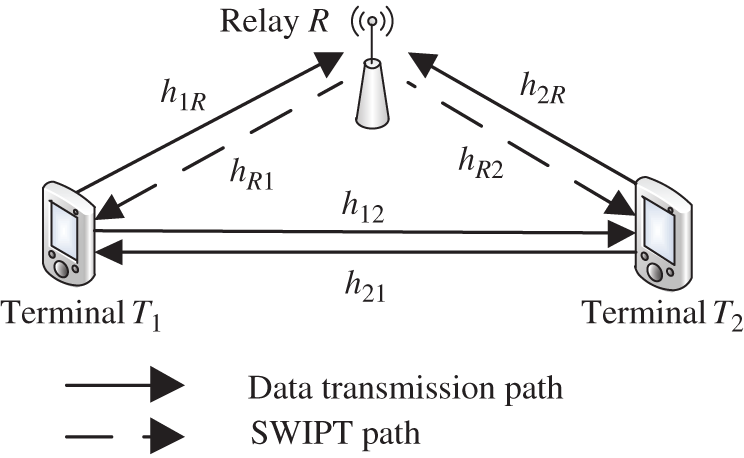
Figure 1: System model of the full-duplex two-way SWIPT relay system
3 System Slot Structure of the Full-Duplex Two-Way SWIPT Relay System
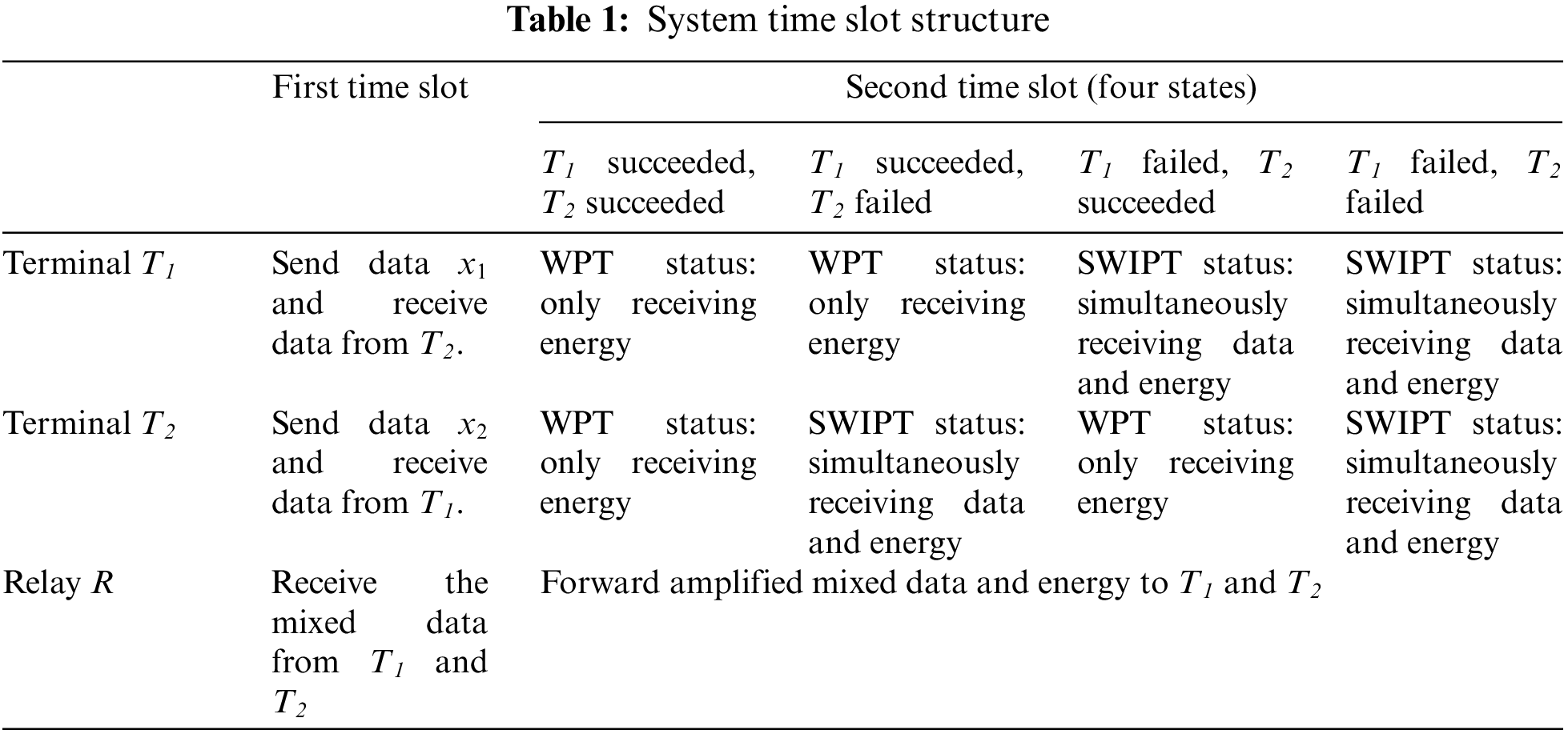
As shown in Tab. 1, the system is divided into two time slots. In the first time slot, data are transmitted and received by two terminals T1 and T2 at the same time, and the relay node receives the mixed signal of the two terminals. Terminal T1 and T2 detect the received signal cyclic redundancy check (CRC) to determine whether the system needs retransmission. The second time slot is the SWIPT time slot, and the relay node sends the retransmission data and energy simultaneously. The second time slot is divided into four states: when two terminals in one time slot receive data successfully, the relay node only transmits energy; when both terminals in the first slot fail to receive data successfully, the relay node mainly transmits data, supplemented by energy transmission; when only one terminal in the first slot receives data successfully, the terminal receiving data successfully mainly transmits energy and another terminal is mainly for data transmission.
with
In the first time slot, two terminals T1 and T2 transmit and receive data at the same time. The relay node receives the mixed signal of the two terminals, so the received signals of the three nodes are as follows:
where
The outage probability of T1 and T2 signals in the first slot is as follows:
where
In the second time slot, the relay node sends retransmission data and energy at the same time. At this moment, the received signals of the two terminals T1 and T2 can be expressed as follows:
where the amplification factor is
If the two terminals are in the state of SWIPT in the second slot, the received information data are as follows:
with
At this time, the received signal-to-noise ratio of terminal T1 is:
where
Similarly, the receiving signal-to-noise ratio (SNR) of terminal T2 is as follows:
where
4 System Throughput and Sum Function of the Full-Duplex Two-Way SWIPT Relay System
In order to briefly describe the receiving process, the following scenario of T2 transmission and T1 reception is taken as an example:
When the CRC detection of the first slot is successful, the power divider allocates all the energy to the energy harvesting, that is
with
If the CRC detection of the first time slot fails, the terminal is in the SWIPT state. T1 combines the signals about
Outage probability
After combining the received signals of two time slots, the outage probability of terminal T1 is as follows:
The outage probability of T1 received signal is the same as that the traditional HARQ scheme. Similarly, we may get the outage probability
The unification throughput of terminals T1 and T2 is
The second slot, if T1 is in SWIPT state, the energy that can be harvested is as follows:
Therefore, the total energy harvested by T1 is
By introducing
Similarly, the power of the energy harvested by terminal T2 is easy to be obtained (The expression is omitted).
To sum up, the total average power of energy harvested by the system is:
In order to describe the performance of the proposed HARQ scheme more comprehensively, the sum function
In this section, the correctness of the above analysis is verified by computer simulation. Suppose the variance
The outage probability of full duplex direct link versus power
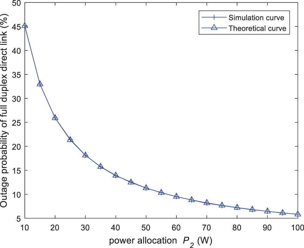
Figure 2: The outage probability of full duplex direct link vs. power P2
For better insights, the throughput of terminal T2 against power P2 is given in Fig. 3. In Fig. 3, the abscissa is the transmitting power
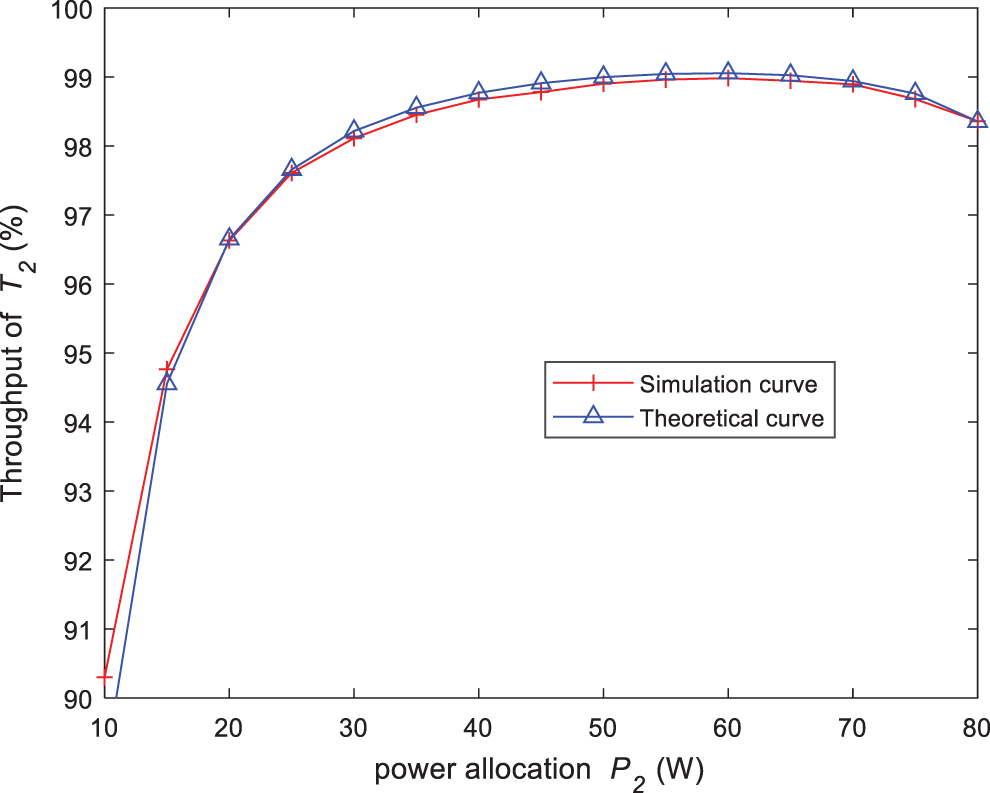
Figure 3: The throughput of terminal T2 against power P2
As shown in Fig. 4, the abscissa is the transmission power
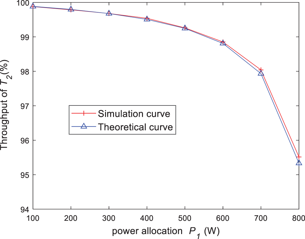
Figure 4: The throughput of terminal T2 against power P1
The relationship between the total throughput of the system and power of the terminal T2 under the symmetrical channel is indicated in Fig. 5. The parameters in Fig. 5 are the same as those set in Fig. 4, except for
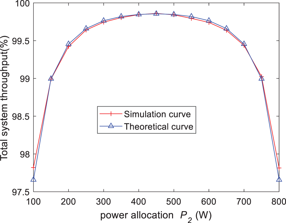
Figure 5: The relationship between the total throughput of the system and power of the terminal T2 under the symmetrical channel
The total system throughput against P2 is illustrated in Fig. 6 under asymmetric channel. The parameter is
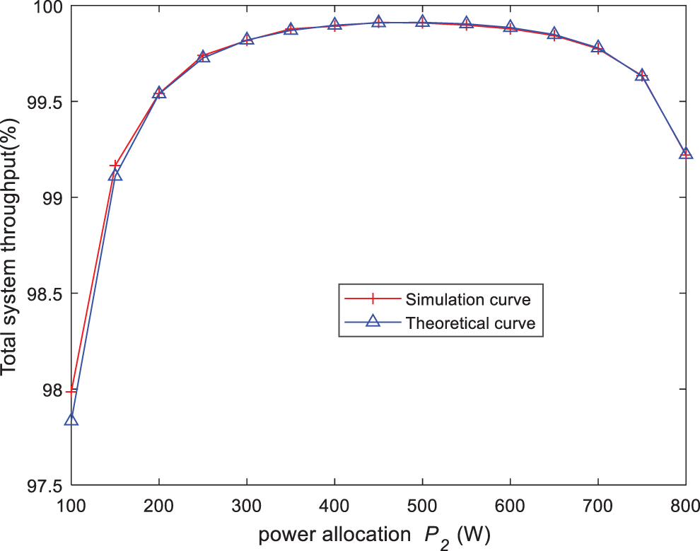
Figure 6: The total system throughput against P2 under the asymmetric channel
Fig. 7 compares the energy harvested-throughput sum function of the two schemes in asymmetric channels (the proposed HARQ scheme and the traditional HARQ scheme). Except for
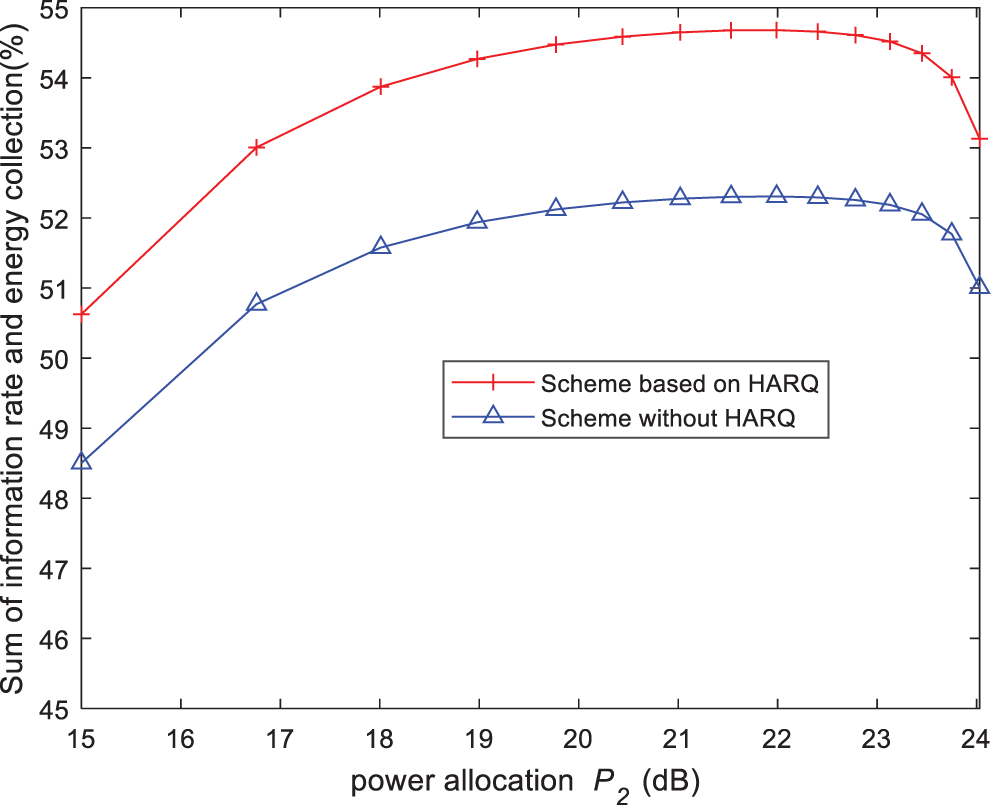
Figure 7: The energy harvested-throughput sum function of the two schemes in asymmetric channels
In order to further explore the potential of the SWIPT relay system, the full duplex two-way SWIPT relay HARQ scheme is proposed in this paper. Firstly, the received signal-to-noise ratio (SNR) is calculated by analyzing the system model and time slot structure. Then the outage probability and throughput are obtained by approximate simplification. Then, the energy harvested power in various states is obtained. Finally, the energy harvested-throughput sum function are constructed. Simulation results show that the proposed HARQ scheme has better energy harvested-throughput sum function than the traditional HARQ scheme.
Acknowledgement: The authors would like to thank the anonymous reviewers for their constructive comments and suggestions.
Funding Statement: This work was supported by the National Natural Science Foundation of China (Grants No. 61701251, 62071244, 62071249, 61872423, 61801236 and 61806100), Open Fund of Key Laboratory of Icing and Anti/De-icing (Grant No. IADL20190105) and the Natural Science Foundation of Jiangsu Province (Grants No. BK20160903).
Conflicts of Interest: The authors declare that they have no conflicts of interest to report regarding the present study.
References
1. Al-Baidhani, M. Vehkapera and M. Benaissa, “Simultaneous wireless information and power transfer based on generalized triangular decomposition,” IEEE Transactions on Green Communications and Networking, vol. 3, no. 3, pp. 751–764, 2019. [Google Scholar]
2. T. A. Le, Q. Vien, H. X. Nguyen, D. W. K. Ng and R. Schober, “Robust chance-constrained optimization for power-efficient and secure SWIPT systems,” IEEE Transactions on Green Communications and Networking, vol. 1, no. 3, pp. 333–346, 2017. [Google Scholar]
3. Y. Ji, W. Duan, M. Wen, P. Padidar and P. Ho, “Spectral efficiency enhanced cooperative device-to-device systems with NOMA,” IEEE Transactions on Intelligent Transposition Systems, vol. 99, pp. 1–11, 2020. [Google Scholar]
4. H. Zhu, D. Gao and S. Zhang, “A perceptron algorithm for forest fire prediction based on wireless sensor networks,” Journal of Internet of Things, vol. 1, no. 1, pp. 25–31, 2019. [Google Scholar]
5. M. Okhovvat and M. R. Kangavari, “Tslbs: A time-sensitive and load balanced scheduling approach to wireless sensor actor networks,” Computer Systems Science and Engineering, vol. 34, no. 1, pp. 13–21, 2019. [Google Scholar]
6. S. Kaur and V. K. Joshi, “Hybrid soft computing technique based trust evaluation protocol for wireless sensor networks,” Intelligent Automation & Soft Computing, vol. 26, no. 2, pp. 217–226, 2020. [Google Scholar]
7. M. K. Shukla, H. H. Nguyen and O. J. Pandey, “Multiuser full-duplex IoT networks with wireless-powered relaying: Performance analysis and energy efficiency optimization,” IEEE Transactions on Green Communications and Networking, vol. 4, no. 4, pp. 982–997, 2020. [Google Scholar]
8. Y. Yan and S. Zhang, “Energy efficiency maximization of the SWIPT-based full-duplex relay cooperative system,” in Proc. IEEE Int. Conf. on Communication Technology, Xi’an, China, pp. 398–403, 2019. [Google Scholar]
9. X. Shi, J. Sun, D. Li, F. Ding and Z. Zhang, “Rate-energy tradeoff for wireless simultaneous information and power transfer in full-duplex and half-duplex systems,” Computer, Materials and Continua, vol. 65, no. 2, pp. 1373–1384, 2020. [Google Scholar]
10. X. Pei, W. Duan, M. Wen, Y. Wu and V. Monteiro, “Socially-aware joint resource allocation and computation offloading in NOMA-aided energy harvesting massive IoT,” IEEE Internet of Things Journal, vol. 8, no. 7, pp. 5240–5249, 2021. [Google Scholar]
11. K. Xu, Y. Gao, Y. Xu and W. Yang, “Diversity-multiplexing tradeoff analysis of AF two-way relaying channel with hybrid ARQ over rayleigh fading channels,” IEEE Transactions on Vehicular Technology, vol. 63, no. 3, pp. 1504–1510, 2014. [Google Scholar]
12. S. Nam, M. Alouini and S. Choi, “Iterative relay scheduling with hybrid ARQ under multiple user equipment (type II) relay environments,” IEEE Access, vol. 6, pp. 6455–6463, 2018. [Google Scholar]
13. J. Su, R. Xu, S. Yu, B. Wang and J. Wang, “Redundant rule detection for software-defined networking,” KSII Transactions on Internet and Information Systems, vol. 14, no. 6, pp. 2735–2751, 2020. [Google Scholar]
14. D. Kim, S. Park, H. Ju and D. Hong, “Transmission capacity of full-duplex-based two-way ad hoc networks with ARQ protocol,” IEEE Transactions on Vehicular Technology, vol. 63, no. 7, pp. 3167–3183, 2014. [Google Scholar]
15. H. Zhu, B. Smida and D. J. Love, “An efficient network-coded ARQ scheme for two-way wireless communication with full-duplex relaying,” IEEE Access, vol. 7, pp. 131995–132009, 2019. [Google Scholar]
16. V. Towhidlou and M. Shikh-Bahaei, “Improved cognitive networking through full duplex cooperative ARQ and HARQ,” IEEE Wireless Communications Letters, vol. 7, no. 2, pp. 218–221, 2018. [Google Scholar]
17. M. Li, J. Lin, L. Zhong, M. Wang and W. Lv, “Cooperative relay based on exploiting hybrid ARQ,” China Communications, vol. 16, no. 9, pp. 187–200, 2019. [Google Scholar]
18. M. Salehi Heydar Abad, O. Ercetin, T. Elbatt and M. Nafie, “SWIPT using hybrid ARQ over time varying channels,” IEEE Transactions on Green Communications and Networking, vol. 2, no. 4, pp. 1087–1100, 2018. [Google Scholar]
Cite This Article
 Copyright © 2023 The Author(s). Published by Tech Science Press.
This work is licensed under a Creative Commons Attribution 4.0 International License , which permits unrestricted use, distribution, and reproduction in any medium, provided the original work is properly cited.
 Downloads
 Citation Tools