
 Submit a Paper
 Propose a Special lssue
 Open Access
ARTICLE

Six Generation Load Cells Solution Based Congestion Management Control Purpose
1 Taif University-Khurma Univ. College-Department of Computer Sciences, Khurma, 2935, Kingdom of Saudi Arabia
2 Research Groups on Intelligent Machines Lab. National School of Engineering of Sfax, Sfax, 3038, TN
* Corresponding Author: Chafaa Hamrouni. Email:
Computers, Materials & Continua 2023, 74(3), 6445-6460. https://doi.org/10.32604/cmc.2023.026441
Received 26 December 2021; Accepted 22 February 2022; Issue published 28 December 2022
 View Full Text
 Download PDF
Abstract
Several assessing efforts are approved making both communication and information technologies available. In addition to being a part of universal access and service, we aim at assessing the impact of radio access technologies on universal access indicators. The proposed work demonstrates the possibility of inter-working of all existing Radio Access Technologies (RATs), in a limited area presented in the Six Generation Radio Resources Allocation (6 G-A) network. We propose a solution for the Vertical hand Over (VHO) in 6 G-A heterogeneous system, that adopts Media Independent Handover (MIH) protocol to benefit between different used technologies in a direct communication firstly and facilitate, in addition, coordination between congestion control mechanisms with the mobility management entity. The mathematical model has been developed to deal with locality coverage and broadband needs, based on a methodological approach consisting in integrating parameters linked to access index through radio technologies. This approach has been applied. In practice, it has contributed to highlighting its relative simplicity of implementation, but it is not enough for six-generation system radio access networks. The congestion control mechanism is integrated within the vertical handover process, this proposition is used to prevent each presented congestion state. The media independent handover IS equipment, as well as six G-A equipment which are both considered as the whole architecture key equipment, perform and guaranty this related process. Efficient communication is established besides information exchange between various technologies. Achieved evaluation results are performant and prove that proposed mechanisms are efficient. Both simulation and tests results are accomplished.Keywords
In this work, we describe our proposed congestion control enhancement in 3rd Generation Partnership Project Long-Term Evolution–Advanced (3rd GPP LTE-A) network. Radio Access Networks constitute the important elements of access layers. The architecture of New Generation Network (NGN) identifies the access layer. Each congestion problem can be managed whether network equipment or by the 3rd Generation Partnership Project equipment such as the eNodeB, that’s demonstrates which architecture is adopted by the six-generation network. To optimize, not dependently on which used technology for the underlying access, each vertical handover. A mechanism is operated by the media independent handover architecture, that guaranties its efficiency. The IEEE Media Independent Handover 802.21 protocol determine the framework’s MIH. All technologies for access link layer and the protocol stack higher layer entities in the protocol stack, are identified and determined by the media independent handover framework model. Initially, the media independent handover function entity in the mobile node, is connected directly to a peer MIHF entity on the network side, and then, the Handover procedure takes place. The point of service exchanges MIH messages with a multimode mobile node, this point of service presents an instance of the network-side media independent handover function. for each mobile node an active layer serving the PoA, and a second deeper inside the network. The specific role network node is based on the MIH signals exchange inter-peers, as the Wi-Fi Access Point, WiMAX Base Station, and the 3rd generation partnership project LTE-A eNodeB technologies [1,2], (Fig. 1 illustrates the heterogeneous access environment). The information server (IS): the basic role of this entity is storing generic information about the Radio Access Networks (RANs) provided by the network operator. When an information server exchange directly MIH messages with other MIH network entities, it will be identified as MIH non-PoS entity. Its role is mainly the storage of each radio access networks generic information, and then related mobility management function is necessary added to its entity.
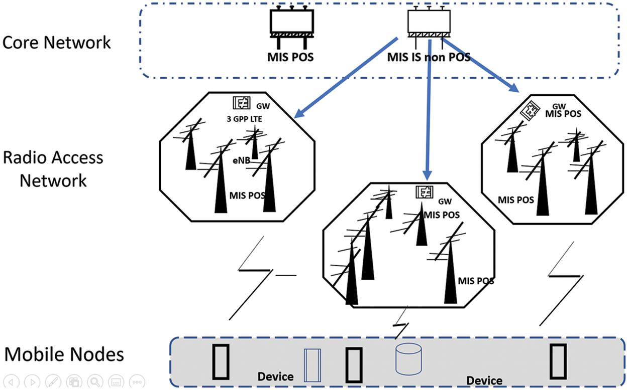
Figure 1: MIH reference framework model
When inter-radio access networks, a balanced load emerges, the information server maintains the situation, or prevent congestion state. In that case, the IS can start or stop any vertical handover due to the stored information.
2 General Phases of Congestion Control Strategy
The more important indicator for a congested system is when the total amount of incoming traffic for a predefined period is greater than the available capacity of the system during this period. Such a state can be detected according to different measurements. If we attempt to classify congestion control algorithms according to their behaviors, we can find two main categories of these algorithms: avoidance strategy and mitigation strategy. In the case of strategy based on avoidance, algorithms maintain the system far away from an overload situation. But, with new communication system generation, this task becomes unsecured because of the explosion of traffic amount, the great number of connected devices, and the diversity of multimedia services. For the mitigation strategy [3], the congestion algorithm [4] is triggered whenever a congestion state is detected to remain the system stable and beyond as fast as possible the congestion. This strategy seems also not coherent with the features of the fourth generation (4G) system [5]. It may also threaten the QoS for end-users. Hence, we propose to combine these two strategies to achieve a congestion control mechanism with four phases, like it is presented in Fig. 2. We detail later the phases of the CC strategy. Prevention phase: the proposed algorithm checks periodically the available capacity of the LTE-A cells [6]. If it is greater than 6 G a predefined threshold, it means that the cell is on the way to being congested. As a preventive action, all new calls or HO requests will be rejected, and the detection phase will be triggered. In the detection phase: the algorithm monitors continuously the system and checks the available capacity of cells to detect if it is greater than the second higher threshold. Even all new calls are rejected. In such a case, a congestion state is announced and the need for fast resolution. Otherwise, the available capacity is increasing, so the algorithm returns to the prevention phase.

Figure 2: Congestion control cycle
Resolution phase: After the detection of an overload situation, the congestion control mechanism [7] is trying to resolve the overload situation. Besides the new call rejection, some handover sessions are triggered to other cells or existing RATs, also traffic rates will be reduced for some users especially those that exceed the predefined rate in the Service Level Agreement (SLA) [8] with the operator. When the available capacity achieves a threshold, the resolution will exit. In the recovery phase: Congestion resolution phase may occur a QoS degradation for some users, a recovery algorithm is needed in order to restore the stability of the system.
3 Hand Over Management Contribution for Congestion
The prevention and detection, the preventative phase of congestion control aim to avoid any potential congestion, and that’s in a dynamic manner based on a network load control operation process. In a lack of resources availability, a handover in the network can results a congestion state, therefore an optimized management of inter-cell/RATs users’ mobility helps to maintain system stability. That is why it is imperative to integrate the congestion control mechanism within the handover management [9]. In general, there are four stages to the handover process: a preparation phase [10], then the target selection, and it is finishing with a strategic operating phase. We consider congestion as a metrics for handover decisions and access to the networks. We integrate the congestion control mechanism based on both handover decisions and target access networks selection. We focus on handover from the WLAN access network to the six G network [11]. HO management metrics end user makes the final HO decision, but also a handover triggering can be suggested by the MIIS entity. Both of these entities can make HO decisions according to the user and network measurements [12]. In our work, we focused on the congestion of the radio link, which explains the potential weight given to the channel capacity metric. In addition, besides channel capacity, we considered some other metrics:
• RSS;
• Mobile user velocity;
• System capacity: 6 G-A deploy OFDMA access technology in the downlink, where symbols are groups into physical resource blocks with a fixed size to 180 KHz. Each 1 ms Transmission Time Interval (TTI) consists of two times slots and 2 PRBs, and each PRB includes 12 subcarriers with and 15 KHz spacing between them [13]. The maximum achievable data rate during a one-time slot is presented by the rate given by all available s, ubcarriers that we call the available capacity. Based on the Shannon formula [14], the maximum achievable capacity for the nth subcarriers is equal to:
equal to:
The maximum available capacity during a one-time slot with N available subcarriers is:
MIH-based VHO decision [15] based on network collected information, the MN decides if a handover will take place or not. This phase is illustrated in Fig. 3, which is presented in the next page. When 802.11 access technology [16] and mobile nodes are connected, server network information states are saved on the MIHF entity. This process is operated, by the use of Net_ Link_ Measurement _ Report.Ind” service primitive, from the IEEE 802.11 access point MAC layer [17] through its MIHF entity. As well for the mobile nodes active interface for each local information, based on MIH _ Link_ MN _ Measurement _ Report_ Ind, MIH _ Cong _ Measures”, as detailed (in Fig. 4). When a request is presented for RRC eNodeB layer by IS in the 3GPP 6G-A [18] network. It a system performance degradation happens, resulting a overload state as well low QoS level [19], the IS proposes a handover to the MN. It can also prevent 3GPP 6G-A cells [20] any potential future handover process. Since “MIH _ Comm _ Scan.req” request was sent by MIH user asks the local MIHF, a list of existing the existing candidates list is mentioned. To select the target, to discover access networks radio candidates. MIH user of the MN can take a to start handover session decision by the MIH user based on QoS degradation [21] and or a vertical handover reception by IS. When request received by the IS entity via “MIH _ Scan.req”. each candidate is identified and a reply must be sent to the mobile terminal MIHF entity.

Figure 3: Illustration of vertical handover preparation
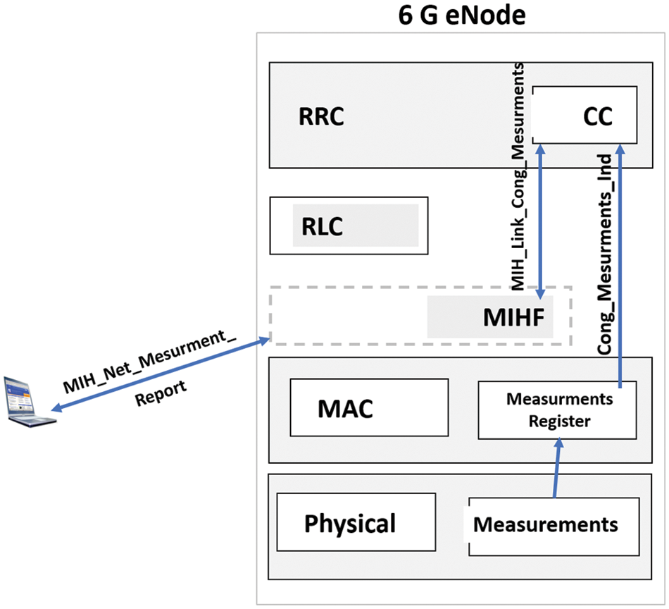
Figure 4: IS and RRC information exchange
Referring to Fig. 4 which is presented below, the MIHF entity in the eNodeB receives “MIH _ Net _ Measurement _ Report.req” from IS entity. Then “MIH _ Link _ Cong _ Measurements _ Request” is emitted to local MAC layer without any parameters. Once measurements are stored, MAC layer generates primitive “Cong _ Measurements. Indication” and send it to the RRC level to the congestion control bloc to collect local measurements like queues as well physical layer measurements. Physical layer measurements [22] and queues measurements must be communicated to the IS entity with “MIH _ Net _ Measurement _ Report. response”.
The described scenario above shall be executed periodically to supervise the cell state in a dynamic and interactive manner. Then, based on the collected measurement, the decision will be made to trigger a handover or not will. The process is monitored by both the mobile user and the MIIS server [23]. Indeed, the MIIS is no longer a storage system only; this entity can make the handover decision in one of the following cases:
• Case 1: overload state;
• Case 2: when enough resources are required;
• Case 3: base station breaks down.
However, even though the MIIS decides to trigger a Vertical Handover Decision (VHOD), the decision must be confirmed by the mobile terminal, which has the authority to make the final decision in order to achieve more user satisfaction.
In addition, to make efficient VHOD for edge users, we deal differently to prevent the Ping-Pong effect, as it is described in Fig. 5. After making the VHOD, when handover is started to another network [24]. After discovering candidates RANs, a selected element is considered as a target network.
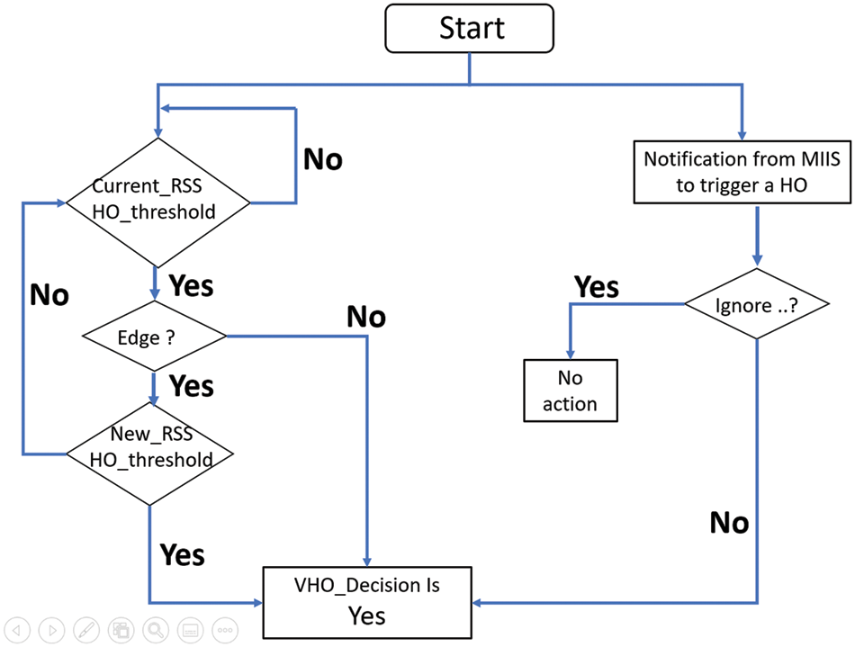
Figure 5: MIH-based vertical handover decision modeling
Fig. 6 illustrates the communication between different entities to select the appropriate destination. Candidate Radio Access Networks (CRANs) state. MIH based target RAT selection After making the VHOD [25], the target selection phase is triggered when the MN decides to start handover to another network. After discovering candidates RANs, one of them will be the target network. Fig. 6 illustrates the communication between different entities to select the appropriate destination. Indeed, the target RAN selection is based on user preferences, application requirements as well as Candidate Radio Access Networks (CRANs) state. The proceeding starts with the request of the MN to the IS entity about CRANs information using the primitive “MIH _ MN _ HO _ Candidate _ Query.Req”. The IS collects CRANs information. As we are interested in the congestion control in LTE_A cells [26]. The “MIH _ Link _ Cong _ Measurements” primitives collects cell congestion measurements from the RRC layer. Then, the IS responds the MN with “MIH _ MN _ HO _ Candidate_ Query. Resp”. Finally, MIH user at the MN executes the target RAN selection algorithm described to get by with a selected target for the handover session. Algorithm. The MIH based Target selection algorithm Ci: available capacity in CRAN I Input List _ CRAN: list of Candidate RANs Begin For i = 1: length (List _ CRAN) If Ci < user _ app _ req CRAN rejected; Remove from the list; End End If List _ CRAN not empty Select the CRAN with higher Ci Else Retransmit “HO _ Candidate _ Query. Request” to MIIS End.
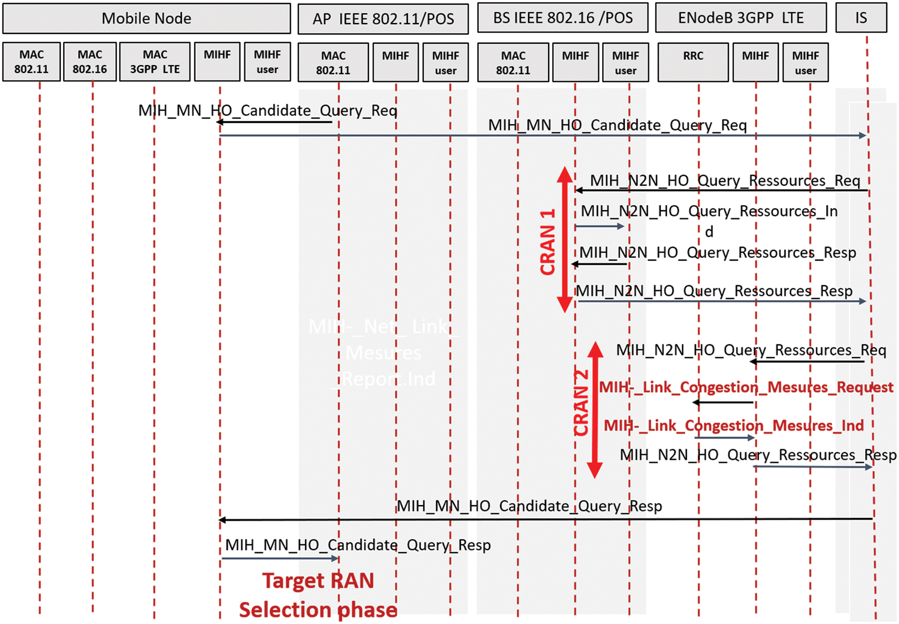
Figure 6: Target RAN selection phase for vertical handover
If the 3GPP 6G-A network store a congestion state, resolving state can be by:
• Decreasing data rate for some users;
• Triggering handover session to other existing RAN;
• Rejecting of new connection requests, as well current handover procedures blocking action, are made to calm down the situation. These actions are carried out by the eNodeB, or by both the eNodeB and the MIIS entities if a congestion state is detected by the MIIS [27]. If congestion state under 6G-A cell/RAT is detected the User’s rate is reduced. It directly works on resolving the problem. In the first congestion resolution action, the data rate will be decreased for two types of users:
• Those whose throughput exceeds that predefined in the service contract with the operator.
• If still necessary, some of those executing applications with a low priority level.
For users with high-priority level applications, like real-time applications, QoS should be maintained as possible. The rate reduction task is triggered by transmitting the “MIH_ NET_ RATE_RED. Ind” primitive from the MIIS to the MIHF entities of covered eNodeBs to be transferred to selected users MIHF entities.
Then, locally on the level of the mobile user, each MIHF entity sends the “MIH_RATE_ RED.Ind” to the MIH user entity in higher layer to increase immediately the user throughput, as illustrated in the Fig. 7. Parameters used with these primitives are described below: the service flow identifier is represented by ID (SFID) parameter that specifies the transport connection. The reduced traffic rate is represented by parameters Maximum sustained traffic rate ̸ Maximum traffic burst ̸ and Minimum reserved traffic rate.

Figure 7: User’s data rate reduction
Reduced traffic duration is mentioned in milli-second (ms). To reduce 6G-A load, the IS, placed network core, trigger a handover to suitable RANs to exceed congestion state. Based on network [28] collected Data, the IS selects those able for new connections. The MIH _ Net _ HO _ trigger Ind” and MIH _ HO_trigger.Ind, as primitives service (Fig. 8) used by IS entity for triggering a handover. IS entity sent first element to MIHF entity user (selected RAN) for HO establishment. Since the primitive reception is accomplished, the “MIH_HO_ trigger. Ind is sent to the MIHF entity. These primitives are characterized with same parameters: MIH _ HO _ trigger. Ind {HO _ DEC (mandatory) and Target_ RAN (mandatory)}. The congestion recovery is executed when the system remains stable, on which the network control entities check affected users when resolving congestion problem. It concerns restoring the allowed data rate according to SLA for users with limited rate, especially for users that perform real time applications [29].
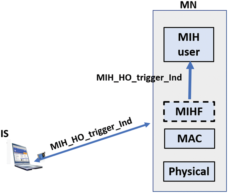
Figure 8: Handover triggering
5 Simulation Tests and Performance Evaluation
The simulated tests for performance evaluation is accomplished. The simulated network, simulation parameters, and results are presented in the subsections below. Simulation scenario. The simulated network is presented in the Fig. 9.
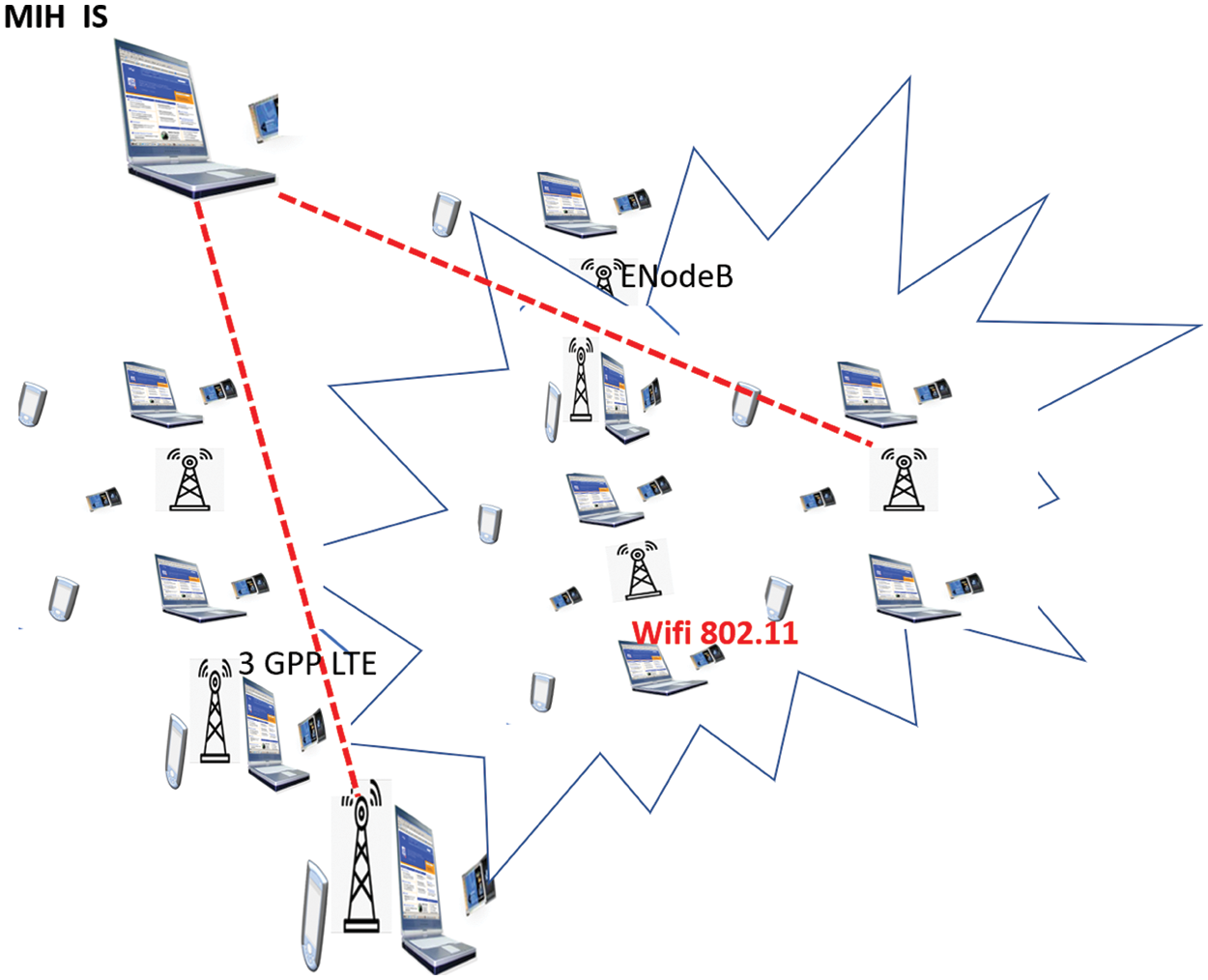
Figure 9: Simulated network
We adopted network architecture composed by:
• Seven hexagonal neighbors 6G-A cells (7 eNodeBs),
• Ratio
• 64 kbps Data: 512 kbps Capacity threshold value 2/3 × maximal offered capacity 802.11 number of users 200 Total number of users Between 200 and 2500 Simulation results and discussion. Metrics used for congestion control mechanism evaluation are:
•
•
•
•
In Figs 10–13, 95% confidence intervals show the accuracy of our estimate situation. In fact, we compare our results with those in case of inactive congestion control mechanisms. Next, in this subsection, we use the notation ECC for enabled congestion control case presented by the blue curve, and DCC when our congestion control mechanism is disabled, which is presented by the red curve in all figures presented below.
• During 6G-A cells measurements, in a closed congestion, MIIS entity declare the eNodeB state. MIIS entity can communicate with eNodeBs, in addition, the 802.11 access point collects measurements.
• By using IS equipment control, when users exercise vertical handover between 3GPP in LTEA and 802.11 environment, under a limited mobile stations number (802.11 access point standard), control messages are exchanged under the two technologies periodically.

Figure 10: Rate of visualization for various users numbers
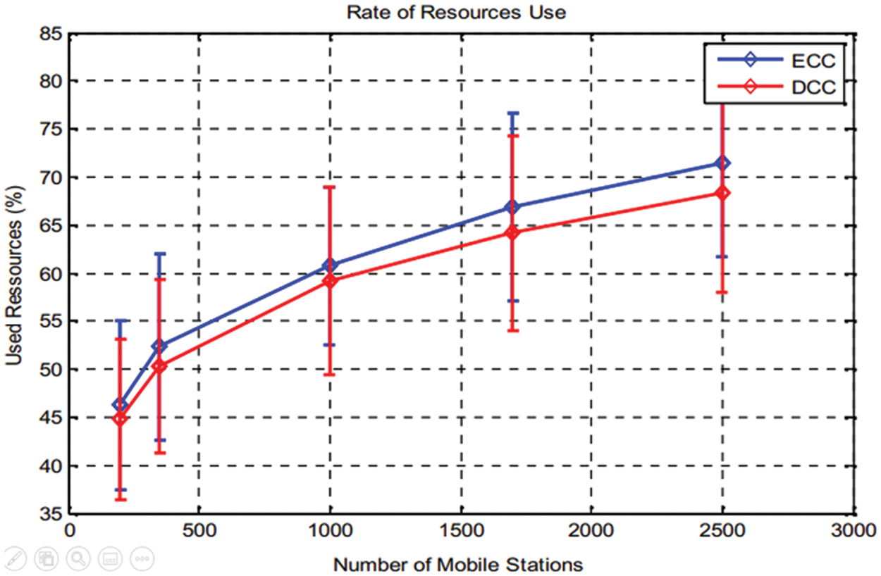
Figure 11: Rate of resources use for various users’ numbers
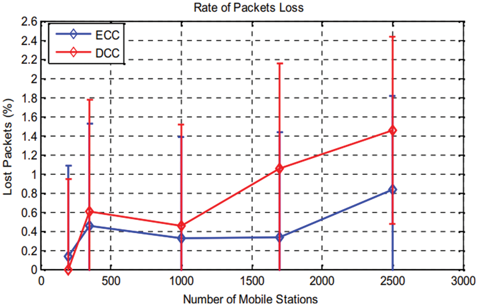
Figure 12: Lost packets rate according to variation of user’s number
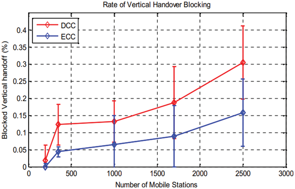
Figure 13: Rate of VHO blocking
We operate related congestion control process in each iteration, if each one takes one TTI. In case of a congestion state, each handover to 6G-A cell is blocked, and transmitted packets are lost. For our uses case study [30] LTE-A network, simulation parameters are presented in Table 1. The parameters Description 6G-A bandwidth 20 MHz (50 RB et 180 KHz per RB).
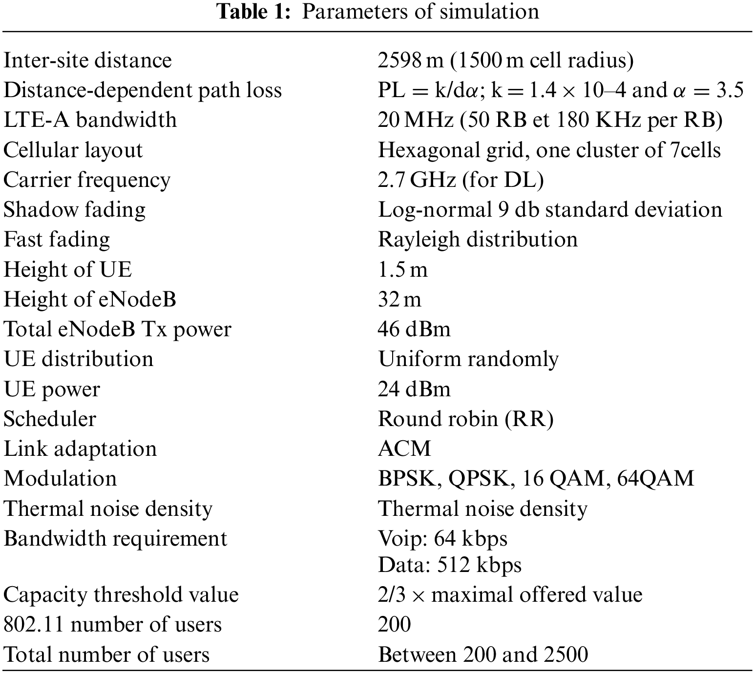
Fig. 10, which is presented above, presents the rate of signalization for a various number of users, for the two cases: ECC and DCC, shows both ECC and DCC solution, where signalization rate for several users is identified [31]. As graphically demonstrated signalization rate is proportional to user’s number, except the ECC solution, a higher value is measured compared to the DCC solution. This can be explained by the more user’s number operate in the net, the more congestion state is being closer, the more congestion prevention actions and notification are generated. By ECC employment, if 2500 users are connected, the rate achieves 30%, standard error margin does not exceed 8% (Fig. 10). As shown difference rate average value is 7%. In fact, this result meets well the NGN aspirations to proposed solution proves the network performance. Its signalization rate, for any user’s number, able to maintains a high level for it. The rate of used resource use (Fig. 11), these exploited resources rate is proportional to users’ number [32]. We constate that for any resources’ utilization rate augmentation is because of an increase of mobile stations for both DCC or ECC. But compared to DCC solution a slight increase is stored for the ECC about 4%. In case 2500 users (ECC), the resources rate used reaches 72%, and 68% in the DCC case. These results are considered good, which reflects a good radio resources management that is maintained along simulation time. Furthermore, we can conclude that our solution allows a good adaptation of the traffic circulating in the network to the provided bandwidth.
The Fig. 12 shows packet loss rate according to the various number of users for both cases. We can conclude from this result: users interval numbers from 350 to 1000, an increase of rate (for ECC solution), and 0.5% in the case of DCC solution, this rate increase until1.1% (for 1800 users). This augmentation is made peak by peak. In case of ECC, the rate is stabilized until 0.8% for users interval numbers from 1000 to 2500. Thus it can be considered as low. The error rate interval for both cases is around 1%. Fig. 13 shows a request to 6G-A network, so by increasing the users’ numbers, blocked VHO increases for both ECC and DCC solution. In practice, lost packets resulting from congestion are omitted, by using proposed mechanism for congestion control with an optimized QoS.
But, in the case of ECC, the rate is always lower than the DCC case. Indeed, a VHO request to the 3GPP 6G-A network may be blocked when there are not enough resources that meet the needs of the user’s application, or for load balancing purposes between networks as well as in case of congestion state; all VHO requests are blocked. That is why, our solution of congestion control aims to avoid congestion state, so avoiding the maximum of VHO request blocking. But, in the ECC situation, with1750 users the rate stored lower than 0.1%, and it increases in DCC situation to0.18%. when users number reaches 2500, in ECC situation the rate increases to 0.15%, but for the DCC situation, it increases to .3%. The error rate is around 0.1%. Based on proposed solution for congestion control, the rate of vertical handover block has decreased by half, compared with the DCC case. In case of mobile networks, movement velocity must be considered. We generated, in Fig. 14, the packet loss rate according to mobile users’ velocity with a fixed number of users that is equal to 2000 users. Fig. 14, shows that until a speed of 175 km/h there is no packet loss: in ECC situation the rate reaches 3.2%, whereas in DCC situation it is 7.5%.
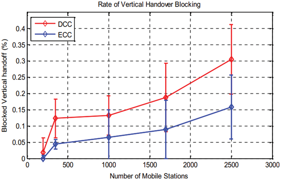
Figure 14: Packets loss rate according to user’s velocity
Experimentally, a user with a high-speed motion increases its packets loss risks probability, due to achieved packet loss rates, the proposed solution reduces any congestion resulting packets loss.
One of the key features of 6 G-A network is the interworking between all existing RATs in a limited area that we considered in our first contribution presented in this chapter. Indeed, we proposed a solution for VHO process in 6G-A heterogeneous system and we adopted MIH protocol to benefit from direct communication between different technologies, to ensure entity mobility as well as scheduling congestion step control mechanism. To mention and prevent a congestion state, we integrate vertical handover technic with mechanism of congestion control. The proposed process is performed by both the 6G-A equipment and the MIH IS equipment based on an efficient and secure exchange data. Experimental results are validated. In the next chapter, we will extend our work by focusing on the load factor to maintain balancing load between 6G-A cells and to prevent overload state.
Acknowledgement: The author would like to acknowledge the Dean of the Khurma University College and the Taif University Department of Scientific Research in the Kingdom of Saudi Arabia for motivation to accomplish the research work.
Funding Statement: The authors declare no specific funding was received for this work.
Conflicts of Interest: The authors declare that they have no conflicts of interest to report regarding the present research work.
References
1. F. Forni, Y. V. Boom, E. Tangdiongga and T. Koonen, “Multiband LTE-A and 4-PAM signals over large-core plastic fibers for in-home networks,” Institute of Electrical and Electronics Engineers Access Nology Letters, vol. 28, no. 7, pp. 2281–2284, 2016 [Google Scholar]
2. M. Charitos, D. Berkovskyy, A. A. Goulianos, T. Mizutani and F. ila, “Geoffrey Hilton”Institute of Electrical and Electronics Engineers Access, vol. 12, no. 3, pp. 3791–3799, 2018. [Google Scholar]
3. W. Guo, J. Fan, G. Y. Li, Q. Yin, X. Zhu et al., “MIMO transmission with vertical sectorization forLTE-A downlin,” Institute of Electrical and Electronics Engineers Access Wireless Communications Letters, vol. 5, no. 8, pp. 372–375, 2016. [Google Scholar]
4. A. Nuseirat and X. Y. Li, “WiMAX/OFDMA burst scheduling algorithm to maximize scheduled data,” Institute of Electrical and Electronics Engineers Access Transactions on Mobile Computing, vol. 11, no. 2, pp. 1692–1705, 2011. [Google Scholar]
5. A. He, L. Wang, M. Elkashlan, Y. Chen and K. Wong, “Spectrum and energy efficiency in massive MIMO enabled HetNets: A stochastic geometry approach,” Institute of Electrical and Electronics Engineers Access Communications Letters, vol. 9, no. 15661687, pp. 2294–2297, 2015. [Google Scholar]
6. M. Gerasimenko, D. Molt, R. Florea, S. Andreev, Y. Kouch et al., “Cooperative radio resource management in heterogeneous cloud radio access networks,” Institute of Electrical and Electronics Engineers Access, vol. 3, no. 5, pp. 397–406, 2015. [Google Scholar]
7. C. Papathanasiou, N. Dimitriou and L. Tassiulas, “Dynamic radio resource and interference management for MIMO-OFDMA mobile broadband wireless access systems,” Computer Networks, vol. 57, no. 1, pp. 3–16, 2013. [Google Scholar]
8. K. Akkarajitsakul, E. Hossain, D. Niyato and D. I. Kim, “Game theoretic approaches for multiple access in wireless networks: A survey,” Institute of Electrical and Electronics Engineers Access Communication Surveys and Tutorials, vol. 13, no. 3, pp. 372–395, 2011. [Google Scholar]
9. M. G. Kibria, K. Nguyen, G. P. Villardi, O. Zhao, K. Ishizu et al., “Big data analytics, machine learning, and artificial intelligence in next generation wireless networks,” Institute of Electrical and Electronics Engineers Access, vol. 13, no. 4, pp. 372–395, 2019. [Google Scholar]
10. J. Tang, D. K. C. So, E. Alsusa, K. A. Hamdi and A. Shojaeifard, “Resource allocation for energy efficiency optimization in heterogeneous networks,” Institute of Electrical and Electronics Engineers Access Journal on Selected Areas in Communications, vol. 33, no. 10, pp. 2104–2117, 2015. [Google Scholar]
11. M. Sahin and H. Arslan, “MIMO-OFDMA measurements, reception, testing, and evaluation of WiMAX MIMO signals with a single channel receiver,” Institute of Electrical and Electronics Engineers Transactions on Instrumentation and Measurement, vol. 58, no. 3, pp. 713–721, 2008. [Google Scholar]
12. Y. Han, “Feedback capacity of the first-order moving average Gaussian channel,” Institute of Electrical and Electronics Engineers Transactions on Information Theory, vol. 52, no. 7, pp. 3063–3079, 2006. [Google Scholar]
13. Y. Shan, W. Chung, G. Kai, I. Chen, H. Zhang et al., “Resource allocation with interference avoidance in OFDMA femtocell networks,” Institute of Electrical and Electronics Engineers Transactions on Vehicular Technology, vol. 61, no. 5, pp. 2243–2255, 2012. [Google Scholar]
14. A. Mukherjee, “Physical-layer security in the internet of things: Sensing and communication confidentiality under resource constraints,” Proceedings of the Institute of Electrical and Electronics Engineers, vol. 103, no. 10, pp. 1747–1761, 2015. [Google Scholar]
15. D. Xu, P. Ren, J. A. Ritcey and Y. Wang, “Code-frequency block group coding for anti-spoofing pilot authentication in multi-antenna OFDM systems,” Institute of Electrical and Electronics Engineers Transactions on Information Forensics and Security, vol. 13, no. 7, pp. 1778–1793, 2018. [Google Scholar]
16. J. Y. Kaakinen, T. Levanen, S. Valkonen, K. Pajukoski, J. Pirskanen et al., “Markku Renfors; Mikko Valkama, efficient fast-convolution-based waveform process for 5G physical layer,” Institute of Electrical and Electronics Engineers on Selected Areas in Communications, vol. 35, no. 6, pp. 1309–1326, 2017. [Google Scholar]
17. S. Furrer and D. Dahlhaus, “Multiple-antenna signaling over fading channels with estimated channel state information: Capacity analysis,” Institute of Electrical and Electronics Engineers Transactions on Information Theory, vol. 53, no. 6, pp. 2028–2043, 2007. [Google Scholar]
18. K. Li and W. Xiaodong, “Cross-layer optimization for LDPC-coded multi rate multiuser systems with QoS constraints,” Institute of Electrical and Electronics Engineers Transactions on Signal Processing, vol. 54, no. 7, pp. 2567–2578, 2006. [Google Scholar]
19. K. Kritikos, “Mixed-integer programming for QoS-based Web service matchmaking dimitris plexousakis,” Institute of Electrical and Electronics Engineers Transactions on Services Computing, vol. 2, no. 2, pp. 122–139, 2009. [Google Scholar]
20. J. Du, L. Zhao, J. Feng, J. Xin and Y. Wang, “Enhanced PSO based energy-efficient resource allocation and CQI based MCS selection in LTE-A heterogeneous system,” China Communications, vol. 13, no. 11, pp. 197–204, 2016. [Google Scholar]
21. M. Assaad and M. Debbah, “Transmit power minimization in small cell networks under time average QoS constraints,” Institute of Electrical and Electronics Engineers on Selected Areas in Communications, vol. 33, no. 10, pp. 2087–2103, 2015. [Google Scholar]
22. P. Annamalai, J. Bapat and D. Das, “Coverage enhancement for MTC devices using reduced search viterbi decoder across RATs,” Institute of Electrical and Electronics Engineers Communications Letters, vol. 20, no. 9, pp. 1892–1895, 2016. [Google Scholar]
23. P. Dat, A. Kanno, N. Yamamoto and T. Kawanishi, “Simultaneous transmission of multi-RATs and mobile fronthaul in the MMW bands over an IFoF system,” in 2017 Optical Fiber Communications Conf. and Exhibition (OFCInstitute of Electrical and Electronics Engineers Conf., vol. 3, no. 7, pp. 653–671, 2017. [Google Scholar]
24. L. Wu, K. Sandrasegaran and M. Elkashlan, “A system level simulation model for common radio resource management,” in 15th Asia-Pacific Conf. on Communications, vol. 12, no. 4, pp. 215–221, 2009. [Google Scholar]
25. M. E. A. Fekair, A. Lakas and A. Korichi, “CBQoS-Vanet: Cluster-based artificial bee colony algorithm for QoS routing protocol in VANET,” in Proc. Int. Conf. on Selected Topics in Mobile & Wireless Networking, Cairo, Egypt, pp. 1–8. 2018. [Google Scholar]
26. W. Sun, G. C. Zhang, X. R. Zhang, X. Zhang and N. N. Ge, “Fine-grained vehicle type classification using lightweight convolutional neural network with feature optimization and joint learning strategy,” Multimedia Tools and Applications, vol. 80, no. 20, pp. 30803–30816, 2021. [Google Scholar]
27. S. Yang and L. Hanzo, “Fifty years of MIMO detection: The road to large-scale MIMOs,” Institute of Electrical and Electronics Engineers Communications Surveys & Tutorials, vol. 17, no. 4, pp. 1941–1988, 2015. [Google Scholar]
28. X. Liu, T. Huang, N. Shlezinger, Y. Liu, J. Zhou et al., “Joint transmit beamforming for multiuser MIMO communications and MIMO radar,” Institute of Electrical and Electronics Engineers Transactions on Signal Processing, vol. 68, no. 14, pp. 3929–3944, 2020. [Google Scholar]
29. K. T. Phan, T. L. Ngoc and L. B. Le, “Optimal resource allocation for buffer-aided relaying with statistical QoS constraint,” Institute of Electrical and Electronics Engineers Transactions on Communications, vol. 64, no. 3, pp. 959–972, 2016. [Google Scholar]
30. S. Hussein, S. Hussein and E. M. Mohamed, “Efficient channel estimation techniques for MIMO systems with 1-bit ADC,” China Communications, vol. 17, no. 5, pp. 50–64, 2020. [Google Scholar]
31. D. T. Hoang, P. Wang, D. Niyato and E. Hossain, “Charging and discharging of plug-In electric vehicles (PEVs) in vehicle-to-grid (V2G) systems: A cyber insurance-based model,” IEEE Access, vol. 5, pp. 732–754, 2017. [Google Scholar]
32. C. Liu, K. T. Chau, D. Wu and S. Gao, “Opportunities and challenges of vehicle-to-home, vehicle-to-vehicle, and vehicle-to-grid technologies,” Proceedings of the IEEE, vol. 101, no. 11, pp. 2409–2427, 2013. [Google Scholar]
Cite This Article
 Copyright © 2023 The Author(s). Published by Tech Science Press.
This work is licensed under a Creative Commons Attribution 4.0 International License , which permits unrestricted use, distribution, and reproduction in any medium, provided the original work is properly cited.
 Downloads
 Citation Tools