
 Submit a Paper
 Propose a Special lssue
 Open Access
ARTICLE

Design of Ka-Band Phased Array Antenna with Calibration Function
1 Aerospace Information Research Institute (AIR), Chinese Academy of Sciences, Beijing, 100094, China
2 School of Electronic, Electrical and Communication Engineering, University of Chinese Academy of Sciences, Beijing, 101408, China
3 University of Science and Technology Beijing, Beijing, 100083, China
4 Beijing University of Posts and Telecommunications, Beijing, 100876, China
5 Audio Analytic, Cambridge, UK
* Corresponding Author: Xingyao Zeng. Email:
Computers, Materials & Continua 2023, 74(3), 6251-6261. https://doi.org/10.32604/cmc.2023.027114
Received 11 January 2022; Accepted 30 March 2022; Issue published 28 December 2022
 View Full Text
 Download PDF
Abstract
In this paper, we have proposed a novel structure of Ka-band based phased array antenna with calibration function. In the design of Ka-band antenna, the active phased array system is adopted and the antenna would work in the dual polarization separation mode. We have given out the schematic diagram for the proposed Ka-band antenna, where the Ka-band antenna is in the form of waveguide slot array antenna, with 96 units in azimuth and 1 unit in distance. Each group of units is driven by a single-channel Transmitter/Receiver (T/R) component, and the whole array contains 192 T/R components in total. The size of the T/R component is 55 mm (length) × 50 mm (width) × 5.8 mm (height), 3 Sub-micro Sub-Miniature Push-on (SSMP) blind sockets and a 21-core low-frequency socket are designed on the two sides of the T/R component. In order to meet the technical specifications of phased array antenna, the Ka-band transceiver component is designed based on Low Temperatrue Co-fired Ceramic (LTCC) technology to achieve miniaturization and lightweight. In our approach, the feed network includes two parts: transceiver network and calibration network. The transceiver network consists of 24 1:8 time-delay power dividers, 12 two-way power dividers and 2 six-way time-delay power dividers. The power supply required by the Ka-band antenna unit is provided to each active component by the power module after Ka band wavelet control distribution. Simulation and measurement results are given in the form of standing wave and scanning capability.Keywords
At present, the phase array technology is widely used, such as satellite communication [1], radar detection [2], and environmental and resource technology [3]. Phased array technology has the following advantages: flexible beam, multiple independent beams can be formed simultaneously, high target capacity, good adaptability to complex target environments, and good anti-jamming performance. As the core component of phased array radar, the research on phased array antenna is very necessary [4–6].
In the development and use of phased array systems, calibration is the most important aspect. The currently available calibration methods, such as the direct method [7], may no longer be sufficient for a wide range of application environments. When dealing with broadband phased arrays with a large number of components, field calibration techniques may not be appropriate due to the size and number of radio frequency sampling devices. In addition, the analytical calibration may be erroneous due to the specification requirements of the relevant application environment.
There are many research works for the calibration of phased array antennas. Shi et al. [8] designed low attenuation, low voltage standing wave ratio and transmission double-line for the calibration of x-band active phased array antennas. The transmission double-line is used to monitor and correct the element phase error of an active phased-array antenna. Li et al. [9] proposed a broadband high-gain uniform circular array with calibration unit for smart antennas, and designed and fabricated an array antenna consisting of 15 array units and a calibration unit. Zhang et al. [10] proposed an improved phased array calibration method based on the complex array signal measured by a single probe. Hong et al. [11] proposed a method for inbuilt testing and calibration of phased arrays in free space using coded modulation embedded tests.
In this paper, a Ka-band phased array antenna structure with calibration function is designed for Ka-band. For Ka-band, we design the antenna operating mode of dual-polarization separation mode by using an active phased array system, and give the antenna schematic diagram for the relevant Ka-band. The main contributions are given as follows,
• Each group of units is driven by a single-channel T/R component, and the whole array contains 192 T/R components in total. The size of the T/R component is 55 mm (length) × 50 mm (width) × 5.8 mm (height), 3 SSMP blind sockets and a 21-core low-frequency socket are designed on the two sides of the T/R component.
• In order to meet the technical specifications of phased array antenna, the Ka-band transceiver component is designed based on LTCC technology to achieve miniaturization and lightweight.
• In our approach, the feed network includes two parts: transceiver network and calibration network. The transceiver network consists of 24 1:8 time-delay power dividers, 12 two-way power dividers and 2 six-way time-delay power dividers. The power supply required by the Ka-band antenna unit is provided to each active component by the power module after Ka band wavelet control distribution.
The whole paper is organized as follows. The system overview is introduced and discussed in Section 2. The designed module for the Ka-band phased array antenna is given in Section 3. It is simulated and measured in Section 4. We conclude the whole paper in Section 5.
The Ka-band antenna adopts the solid-state one-dimensional scanning active phased array system and works in dual polarization separation mode [12,13]. It can complete the power amplification of the transmitted signal and radiate electromagnetic energy to the specified airspace, while achieving low-noise amplification and reception of the echo signal. The antenna has the ability of one-dimensional beam scanning with large bandwidth. With calibration function, each T/R component can be calibrated.
The Ka-band antenna consists of 96 H-polarized radiation arrays, 96 V-polarized radiation arrays, 192 single-polarized T/R components, 24 eight-way time-delay power dividers, 12 two-way power dividers, 2 six-way time-delay power dividers, 12 sixteen-way power dividers, 2 six-way power dividers, 1 two-way power divider and 12 Ka-band segment wavelet controllers. Among them, 16 radiation arrays, 16 T/R components, 2 eight-way time-delay power dividers, 1 two-way power divider, 1 sixteen-way power divider and 1 Ka-band segment wavelet controller form a Ka-band antenna sub-module, and the antenna has 12 sub-modules in total. The Ka-band antenna schematic diagram is shown in Fig. 1.
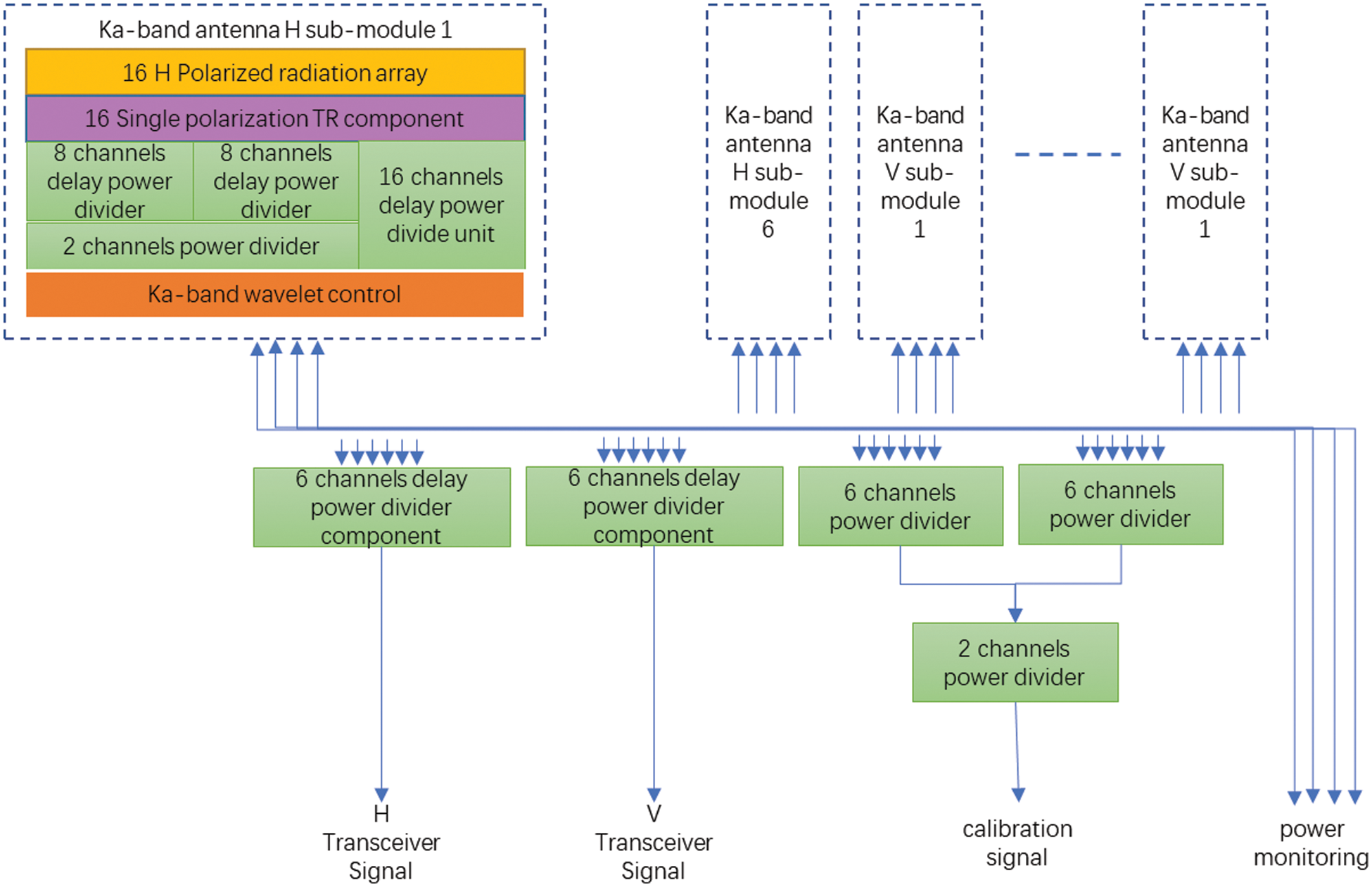
Figure 1: Principle-block diagram of Ka-band phased array antenna element
Ka-band antenna is in the form of waveguide slot array antenna, with 96 units in azimuth and 1 unit in distance. Each group of units is driven by a single-channel T/R component, and the whole array contains 192 T/R components in total.
Fig. 2 shows the structure of antenna transceiver array. The electrical size of the array layer is 576 mm (azimuth) × 27 mm (distance) × 2 (horizontal polarization and vertical polarization), in which there are 1 unit in the distance direction and 96 units in the azimuthal direction. The antenna array adopts the arrangement scheme of rectangular grid. In order to realize the scanning requirements of the antenna, the azimuth distance of the units is determined to be 6 mm.
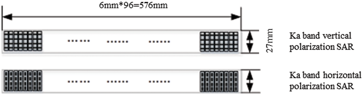
Figure 2: Structure diagram of antenna array
The antenna radiation unit is designed in the form of waveguide slot antenna. The azimuth length of the single horizontal polarization waveguide is 6 mm, and the distance length is 27 mm. The wide edge of the waveguide is slit, and each waveguide has 4 slits to radiate electromagnetic waves. The azimuth length of the single vertical polarization waveguide is 6 mm, and the distance length is 27 mm. The narrow edge of the waveguide is slit, and each waveguide has 4 slits to radiate electromagnetic waves. In the azimuthal array, the rectangular grid arrangement is adopted, and the choke groove is added to increase the isolation degree. The array unit spacing is 6 mm.
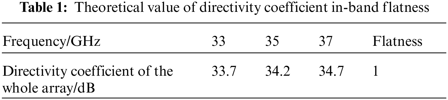
2.3 Antenna Directivity Coefficient
The effective aperture size of Ka-band antenna is 576 mm (azimuth) × 27 mm (distance), and its directional coefficient is 34.4 dB under uniform distribution, as given in Table 1. The difference of in-band directivity coefficient between high and low frequencies was 1 dB.
The Ka-band T/R component is an important part of the active phased array radar antenna [14–16]. Each T/R channel includes receiving channel, transmitting channel and public channel. It includes coupler limiter, low noise amplifier, power amplifier, multi-functional chip, series-parallel conversion chip, etc., with the functions of amplifying, phase-shifting and attenuation of the received and transmitted signals, and power management function to achieve low power consumption and high efficiency.
The main functions are as follows: high power amplification of the transmitted signal during the transmitting period, low noise amplification of the received signal during the receiving period, and transmitter-receiving conversion under the control of T/R signal. The transmitting phase shift, receiving phase shift and receiving gain can be programmed and controlled by the beam control module. The antenna port of each T/R component is set with a calibration directional coupler, and the calibration signal is coupled to output during transmission, and the calibration signal is coupled to input into the receiving channel of T/R component during reception. Each T/R component has a load mode, neither transmitting nor receiving, and both receiving and transmitting are in isolation. The radio frequency (RF) network interface is connected to the matching load. The load mode is controlled by the beam control module. Transmitting and receiving share digital phase shifter, the transceiver control code is separated, and the switching control is completed under the control of T/R signal. The power modulator completes the pulse modulation of the transceiver channel power supply under the control of T/R signal.
The size of the T/R component is 55 mm (length) × 50 mm (width) × 5.8 mm (height), 3 SSMP blind sockets and a 21-core low-frequency socket are designed on the two sides of the T/R component, such layout has the following advantages: it is convenient for the miniaturization and high integration of the components and the array; and it is beneficial to the implementation of thermal control scheme. The internal structure design is shown in Fig. 3.
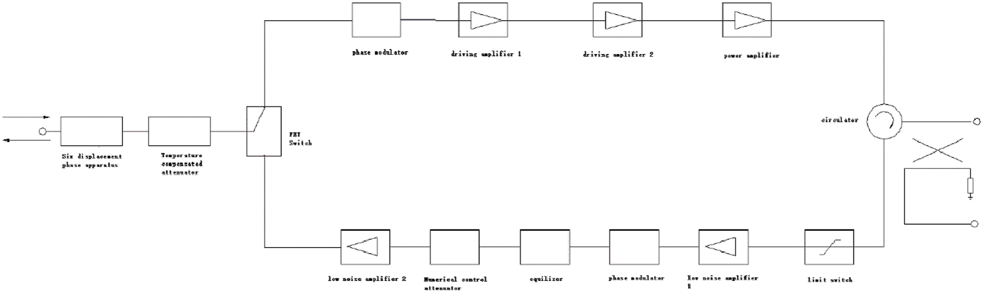
Figure 3: Schematic diagram of transceiver components
In addition to the shell and cover plate, the main internal structure of the module is the power management control PCB and microwave PCB, which are assembled by welding with the shell, as given in Fig. 4.
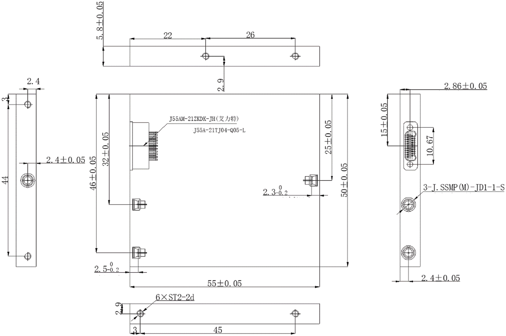
Figure 4: Component structure and size
In order to meet the technical specifications of phased array antenna, the Ka-band transceiver component is designed based on LTCC technology to achieve miniaturization and lightweight. From the functional structure, it is divided into microwave signal circuit layer and power management and control circuit layer. Using LTCC technology, two circuit boards on functional structure can be integrated into one LTCC substrate on physical structure.
Feed network includes two parts: transceiver network and calibration network.
The transceiver network consists of 24 1:8 time-delay power dividers, 12 two-way power dividers and 2 six-way time-delay power dividers. The design delay of T/R component is 1 λ , which cannot meet the delay requirements of antenna beam scanning, 7.5 λ delay should be added to the 1:8 time-delay power dividers with a step of 0.5/1/2/4 λ, and 2 λ delay should be added to the 1:6 time-delay power dividers with a step of 2/4/8/8 λ. Due to the large delay chip insert loss, a transceiver bidirectional amplifier circuit should be added, as shown in Figs. 5–7.
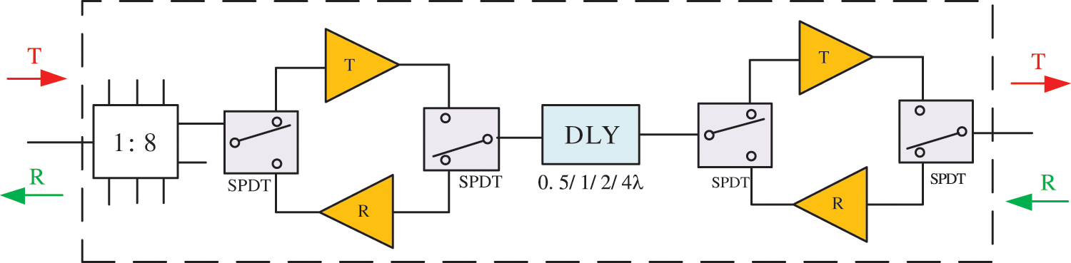
Figure 5: 8-way time-delay power-divide component
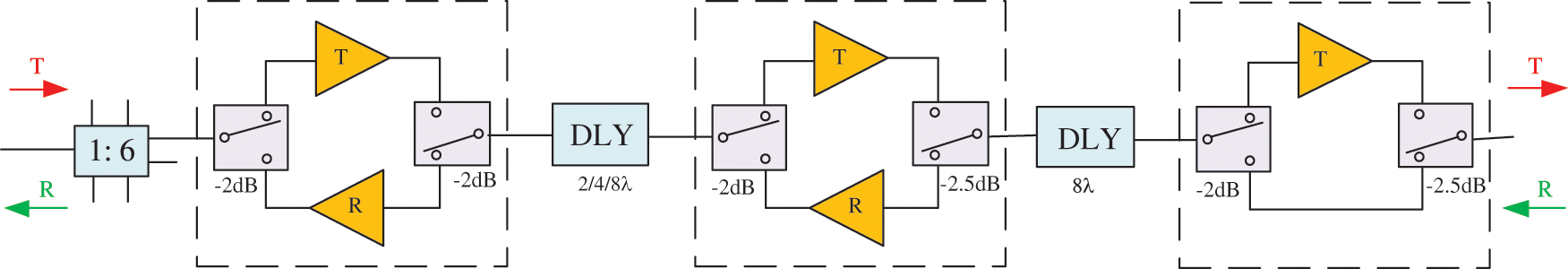
Figure 6: Time-delay power-divide component
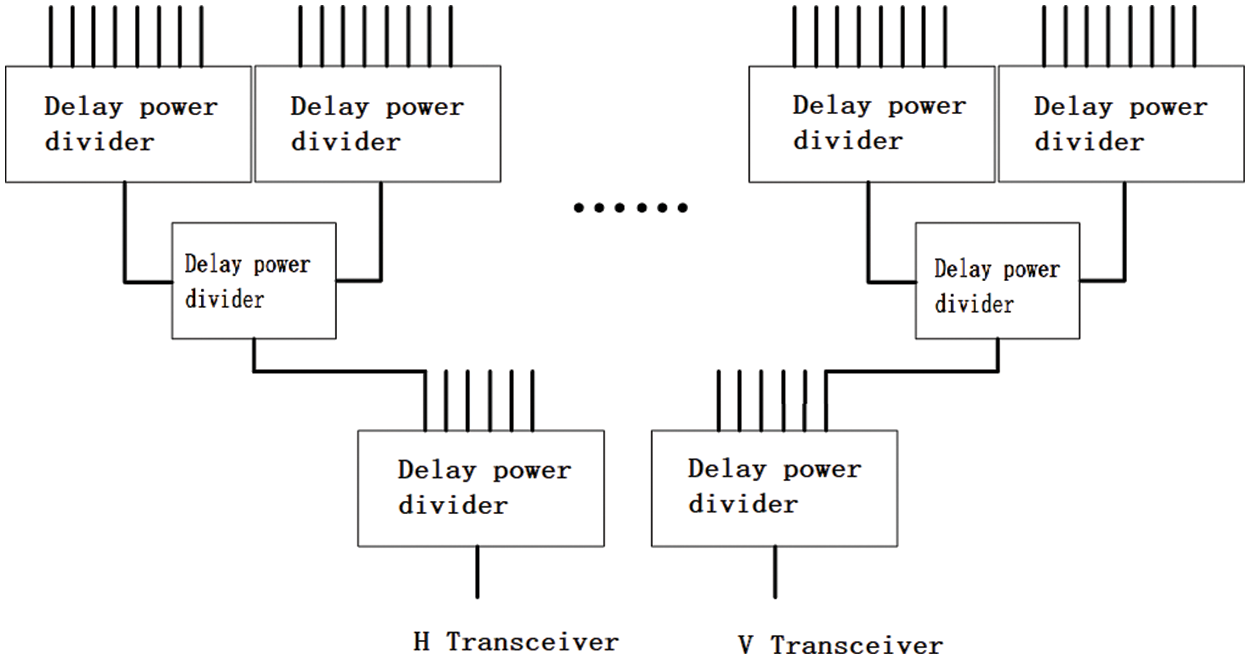
Figure 7: Block diagram of transceiver network
The calibration network only needs to combine the calibration signals of 192 T/R modules and transmit them to the calibration port of microwave combination. Therefore, the calibration network consists of 12 sixteen-way power dividers, 2 six-way power dividers and 1 two-way power divider, as shown in Fig. 8.
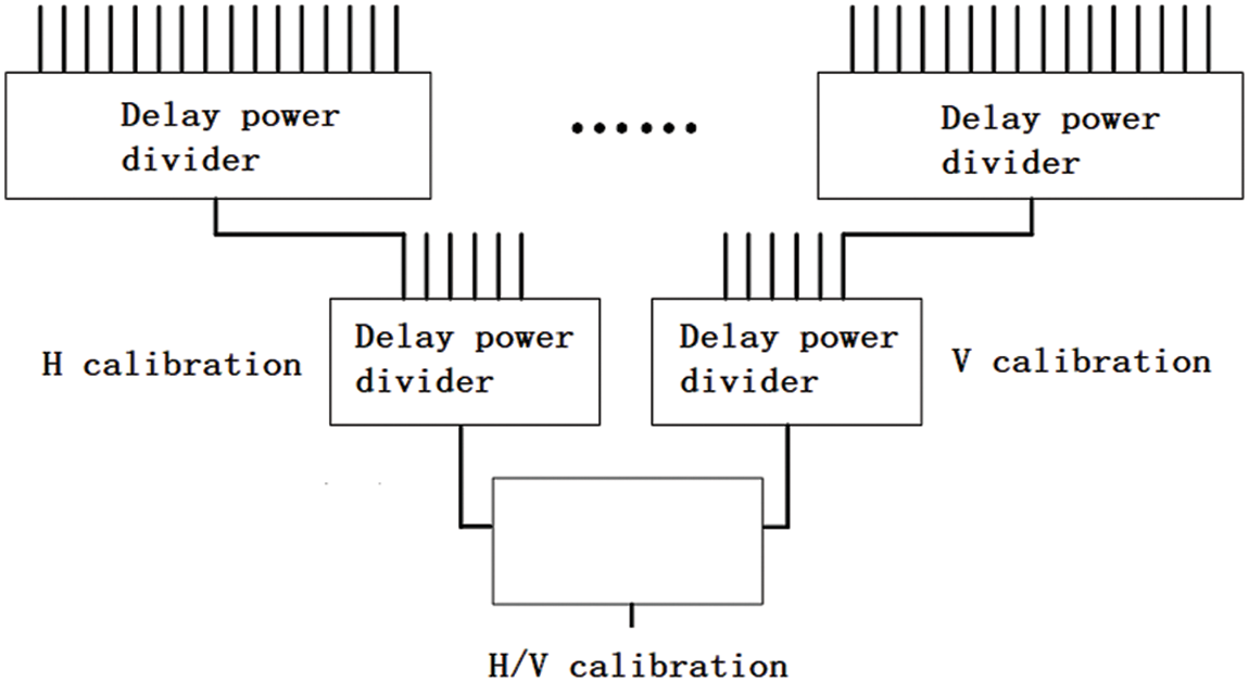
Figure 8: Calibration network
3.3 Power Supply and Beam Control
The power supply required by the Ka-band antenna unit is provided to each active component by the power module after Ka band wavelet control distribution. The control signals required by the antenna are received by the wavelet controller and distributed to each active component. Then the wavelet controller sends all telemetry signals back to the total wave-control module.
The beam-control part performs the following functions: receiving the wave control code from the wave control module, sorting, and distributing it to 192 T/R components and 24 eight-way time-delay power dividers and other controlled units; receiving all monitoring signals from each active unit and pack them to the wave control module. Low voltage differential signaling (LVDS) interface is used to exchange data between the wavelet control module and the wave control module. Beam control block Fig. 9 is shown below.
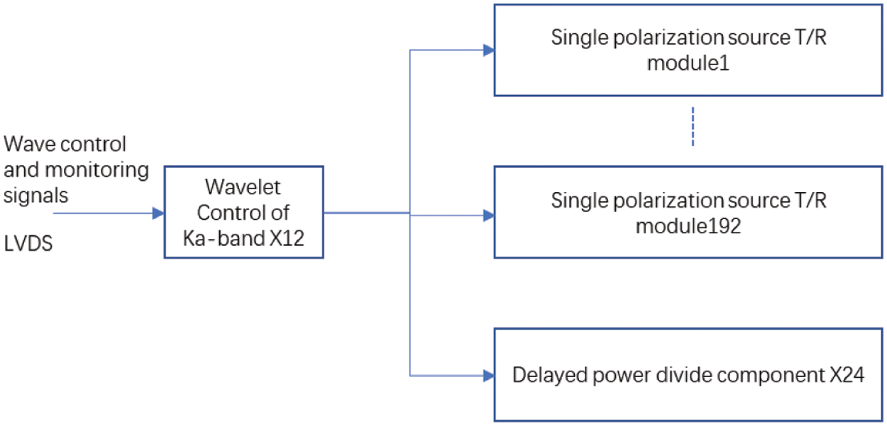
Figure 9: Ka-band phased array antenna unit beam control block diagram
4 Simulation and Measurement Results
The simulation structure diagram of the antenna and the simulation results of the unit standing wave in the antenna array are shown in Figs. 10 and 11. It can be seen that within the entire bandwidth range of 4000 MHz, the reflection coefficient of the port is below 1.8, which meets the requirement of the indicator parameters. Simulation and physical figure of horizontal polarization radiation unit are shown in Fig. 10a, and standing wave simulation and test results of radiation unit given by Voltage Standing Wave Ratio (VSWR) are shown in Fig. 10b. Simulation and physical figure of vertically polarized radiation unit are shown in Fig. 11a, and standing-wave simulation and test results of radiation unit are shown in Fig. 11b. The radiation unit adopts SSMP connector to feed, and the physical standing wave is tested by vector network analyzer 3672 C. Considering that the SSMP-SMA (Sub-Miniature-A) converter is used when testing standing wave, the gap between the simulation results of standing wave and the test results is within the acceptable range.
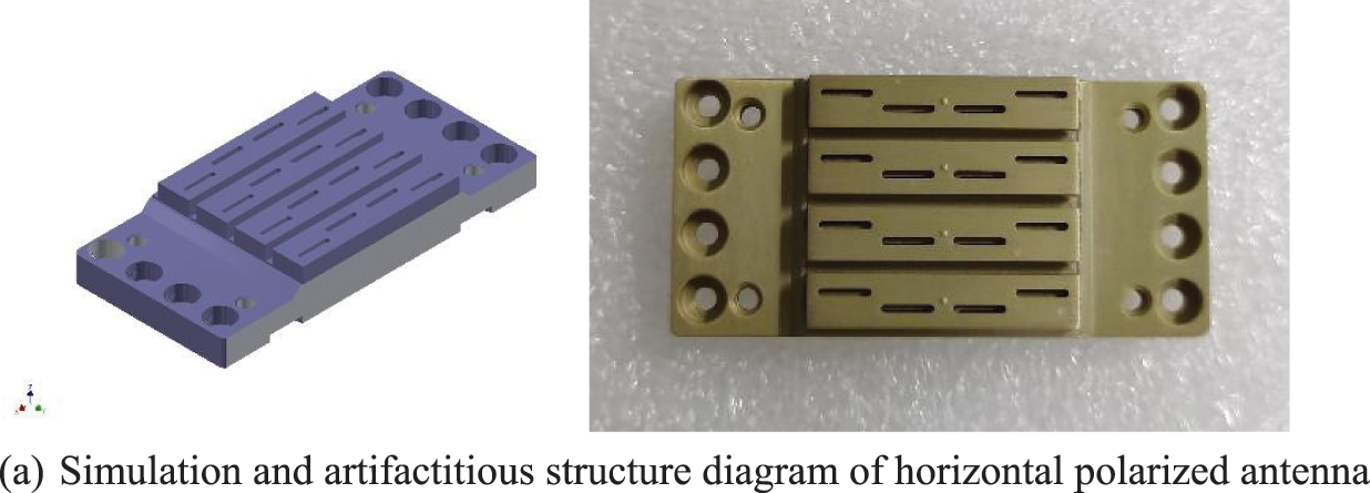
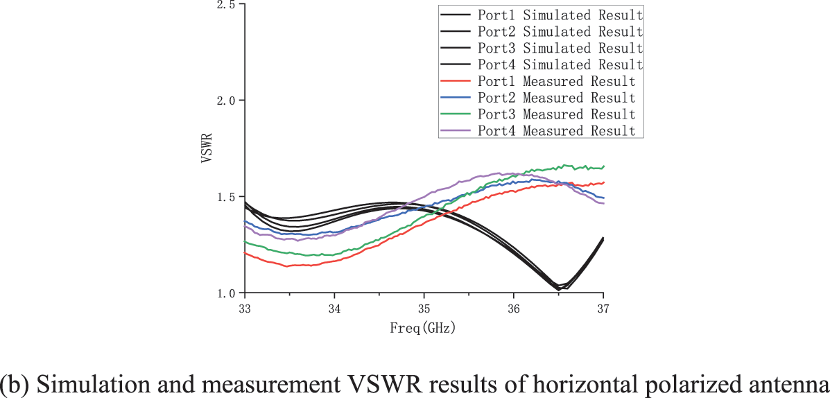
Figure 10: Horizontal polarized Ka-band phased array antenna unit
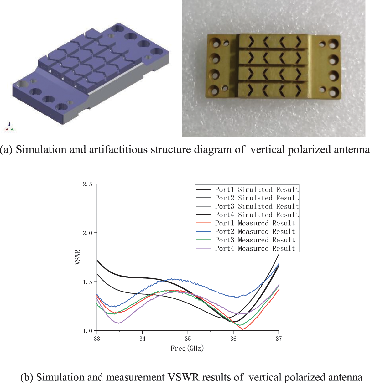
Figure 11: Vertically polarized Ka-band phased array antenna unit
The antenna array adopts 96-element array, and the modeling model and physical object are shown in Fig. 12a below for scanning capability verification. The planar near-field testing system is used to test The antenna direction graph. The antenna scanning capability is given in Fig. 12. As can be seen from the figure, the simulation results are consistent with the measured results at the three key scanning angles 0°, 11° and −11° of horizontal polarization and vertical polarization arrays.
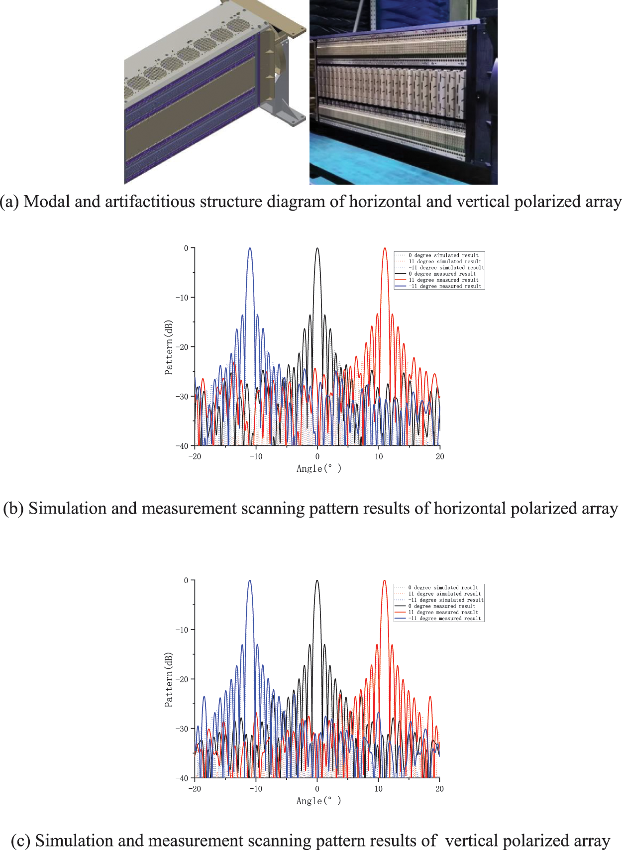
Figure 12: Measured results of Ka-band azimuthal scanning capability
In this paper, a Ka-band phased array antenna structure with calibration function is designed for Ka-band. For Ka-band, we design the antenna operating mode of dual-polarization separation mode by using an active phased array system, and give the antenna schematic diagram for the relevant ka-band. It can be seen that within the entire bandwidth range of 4000 MHz, the reflection coefficient of the port is below 1.8, which meets the requirement of the indicator parameters. In additional, as can be seen from the results figures, the simulation results are consistent with the measured results at the three key scanning angles 0°, 11° and −11° of horizontal polarization and vertical polarization arrays.
Funding Statement: The authors received no specific funding for this study.
Conflicts of Interest: The authors declare that they have no conflicts of interest to report regarding the present study.
References
1. S. Moon, S. Yun, I. Yom and H. L. Lee, “Phased array shaped-beam satellite antenna with boosted-beam control,” IEEE Transactions on Antennas and Propagation, vol. 67, no. 12, pp. 7633–7636, 2019. [Google Scholar]
2. K. H. Kim, H. Kim, D. Y. Kim and H. S. Jin, “Development of planar active phased array antenna for detecting and tracking radar,” in IEEE Radar Conf. (RadarConf18), Oklahoma City, OK, USA, pp. 0100–0103, 2018. [Google Scholar]
3. Z. Ellahi and A. Rehman, “Phased array antenna for the application of device free localization in indoor environments,” in Intelligent Systems Conf. (IntelliSys), London, pp. 1074–1077, 2017. [Google Scholar]
4. S. R. Ahasan, K. Islam, M. M. Khan, M. Masud, G. S. Gaba et al., “Novel compact uwb band notch antenna design for body-centric communications,” Computer Systems Science and Engineering, vol. 40, no. 2, pp. 673–689, 2022. [Google Scholar]
5. H. H. Tran, K. Nguyen-Dang and N. Hussain, “Single-layer wideband circularly polarized antenna using non-uniform metasurface for c-band applications,” Computers, Materials & Continua, vol. 68, no. 2, pp. 2487–2498, 2021. [Google Scholar]
6. O. A. Saraereh, L. Al-Tarawneh, A. Ali and A. M. Hadidi, “Design and analysis of a novel antenna for thz wireless communication,” Intelligent Automation & Soft Computing, vol. 31, no. 1, pp. 607–619, 2022. [Google Scholar]
7. R. Sorace, “Phased array calibration,” in IEEE Int. Conf. on Phased Array Systems and Technology, Dana Point, CA, USA, pp. 533–536, 2000. [Google Scholar]
8. C. Shi and Z. Lu, “A transmission double-line for the calibration system of x-band active phased-array antennas,” IEEE Transactions on Antennas and Propagation, vol. 56, no. 12, pp. 3876–3878, 2008. [Google Scholar]
9. T. Li, F. Zhang, F. Zhang, Y. Yao and L. Jiang, “Wideband and high-gain uniform circular array with calibration element for smart antenna application,” IEEE Antennas and Wireless Propagation Letters, vol. 15, pp. 230–233, 2016. [Google Scholar]
10. F. Zhang, W. Fan, Z. Wang, Y. Zhang and G. F. Pedersen, “Improved over-the-air phased array calibration based on measured complex array signals,” IEEE Antennas and Wireless Propagation Letters, vol. 18, no. 6, pp. 1174–1178, 2019. [Google Scholar]
11. Z. Hong, V. Chauhan, S. Schönherr and B. A. Floyd, “Code-modulated embedded test and calibration of phased-array transceivers,” IEEE Transactions on Microwave Theory and Techniques, vol. 69, no. 3, pp. 1846–1859, 2021. [Google Scholar]
12. A. Smida, “Gain enhancement of dielectric resonator antenna using electromagnetic bandgap structure,” Computers, Materials & Continua, vol. 71, no. 1, pp. 1613–1623, 2022. [Google Scholar]
13. M. M. Khan, A. Sultana, M. Masud, G. S. Gaba and H. A. Alhumyani, “Miniaturized novel uwb band-notch textile antenna for body area networks,” Computer Systems Science and Engineering, vol. 40, no. 3, pp. 1183–1198, 2022. [Google Scholar]
14. H. Yang and B. Yun, “A six bit silicon nitride optical true time delay line for Ka-band phased array antenna,” Journal of Physics Conference Series, vol. 1634, no. 1, pp. 012173, 2020. [Google Scholar]
15. T. Lambard, O. Lafond, M. Himdi, H. Jeuland, S. Bolioli et al., “Ka-band phased array antenna for high-data-rate SATCOM,” IEEE Antennas and Wireless Propagation Letters, vol. 11, pp. 256–259, 2012. [Google Scholar]
16. H. Al-Saedi, S. Gigoyan, W. M. Abdel-Wahab, A. Palizban, A. Taeb et al., “A low-cost Ka-band circularly polarized passive phased-array antenna for mobile satellite applications,” IEEE Transactions on Antennas and Propagation, vol. 67, no. 1, pp. 221–231, 2019. [Google Scholar]
Cite This Article
 Copyright © 2023 The Author(s). Published by Tech Science Press.
This work is licensed under a Creative Commons Attribution 4.0 International License , which permits unrestricted use, distribution, and reproduction in any medium, provided the original work is properly cited.
 Downloads
 Citation Tools