
 Submit a Paper
 Propose a Special lssue
 Open Access
ARTICLE

Efficient Routing Protocol with Localization Based Priority & Congestion Control for UWSN
Electronics and Communication of Engineering, SRM Institute of Science and Technology, Vadapalani, Chennai, 600026, TN, India
* Corresponding Author: S. Sandhiyaa. Email:
Computers, Materials & Continua 2023, 74(3), 4747-4768. https://doi.org/10.32604/cmc.2023.032298
Received 13 May 2022; Accepted 23 September 2022; Issue published 28 December 2022
 View Full Text
 Download PDF
Abstract
The nodes in the sensor network have a wide range of uses, particularly on under-sea links that are skilled for detecting, handling as well as management. The underwater wireless sensor networks support collecting pollution data, mine survey, oceanographic information collection, aided navigation, strategic surveillance, and collection of ocean samples using detectors that are submerged in water. Localization, congestion routing, and prioritizing the traffic is the major issue in an underwater sensor network. Our scheme differentiates the different types of traffic and gives every type of traffic its requirements which is considered regarding network resource. Minimization of localization error using the proposed angle-based forwarding scheme is explained in this paper. We choose the shortest path to the destination using the fitness function which is calculated based on fault ratio, dispatching of packets, power, and distance among the nodes. This work contemplates congestion conscious forwarding using hard stage and soft stage schemes which reduce the congestion by monitoring the status of the energy and buffer of the nodes and controlling the traffic. The study with the use of the ns3 simulator demonstrated that a given algorithm accomplishes superior performance for loss of packet, delay of latency, and power utilization than the existing algorithms.Keywords
Technologies like Wireless Sensor Networks (WSNs) are recognized by various industries as an economical alternative to currently implemented and expensive approaches used in technology [1]. Terrestrial communication is a standard system of WSN which uses radio waves. WSN currently uses many new techniques for better communication. These techniques are also tested by researchers in the field of underwater [2]. The scope for various innovative networking structures has been opened by key technological developments in associated fields. Three-fourths of the earth’s surface is covered by water. People are more curious in this uncharted region. Over the period, happenings of man-made calamities evoke many of them on caring the aquatic regions. The Wireless detector network build undersea fascinated many researchers to create and invent some new applications related to undersea. UWSN (Underwater Wireless Sensor Network) have established many applications as they are used in collecting pollution data, mine surveys, oceanographic information collection, aided navigation, strategic surveillance, sea exploration, military applications, and my surveys [3].
The necessity in underwater applications is transmitting the information from sensor nodes to one-off sinks at the sea surface using multi skips. Fig. 1 shows the general architecture of Underwater Sensor Networks. The sensors kept under the sea get connected using a non-wired acoustic communication network. Autonomous Underwater Vehicles (AUVs), immersed in the water as well as in the Surface sink, at the shallow of the water receive the signals from the nodes that attach those sensors. The AUVs and the surface sink are attached using radio and acoustic communication networks. Surface sinks receive the relays using acoustic communication signs from the nodes which examine indigenous actions that take place under the water with the help of multiple skips [4]. Information gathered from the sinks on the surface to manage UWSNs which got equipped with a satellite transmitter and also the sensors for acoustic communication, thus passes to the land stations.
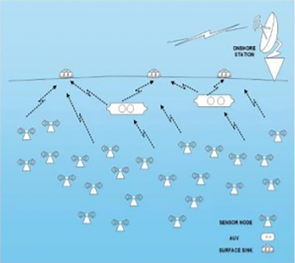
Figure 1: Architecture of UWSN
The main benefit of Underwater sensor nodes design is that it works continuously and properly besides there will be no need for fixing or any service as well as rejuvenation is required for many years. The nodes are not able to do side-side movements independently in underwater networks so they have been arranged with a specific space between them [5]. These sensor nodes remain inactive until they observe an effect. Congestion Control in UWSNs is required in a situation when the nodes of the sensor initiate their production and transfer of information to more than one sink placed on the surface of the water. Thus, congestion control is necessary to avoid the abrupt increase in loads of sink as explained in the above-mentioned situation. The congestion may result in packet losses and slow communication performance since the sensory nodes as well as the sinks depend on the transmittal rate. In UWSNs, congestion is elevated further due to bad routes of transmission. The over-crowding situation that happens during the transmission should be controlled using the schemes in underwater sensory networks [1]. The data communication within the network without any congestion failure should be introduced in the congestion control schemes [4]. Most congestion control schemes assumed that major network losses are due to congestion only which causes more problems in UWSNs. TCP (Transmission control protocol)-based protocols cannot be suitable for UWSNs since they couldn’t be able to find out the difference in packet losses, whether they occur because of over-crowding or route failure [6]. The main reason for this over-crowding is because of the synchronicity loss, all sources connected to one sink, and some overflow that occurs in the buffer [1].
An independent transmission and reception nodes with multiple knowledge-based applications on measurements, oceanographic surveys, catastrophe prevention as well as strategic observations can be done using Underwater sensor networks [1]. A feasible alternative for the under-sea transmission is only through acoustic communication. The acoustic waves are nothing but pressure waves that travel transversely. The main drawback of radio waves is a terrible distribution which results in the weakening of transmission. The acoustic waves create a spherical distribution of transmission because of the signaling and environment features [1]. Severe limitations occur on the power ratio, effectual rates as well as the feasibility of the materials used due to the confining nature of the water in the sea. But the nodes present under the sea water can withstand these severe limitations in the aquatic environment without any need for assistance for years. Already we know that these nodes are arranged with spaces because of their inability to autonomous or intentional lateral movements. They must be kept intact and arranged accordingly to avoid the interruption caused by drifts underwater, thus making them work efficient manner [2].
Khan et al. [7] suggest that a model-free algorithm based on energy and collecting of information to be kept efficiently as well as in balanced conditions using routing protocol. The frequency of the forwarding nodes is chosen on the basics of their residuary power and so joined to their nearby nodes’ power. This selection is done on the basics of their energies making them an energy-effective method and also resulting in increased lifespan. When the empty node gets failed in its recovery procedure then the whole configuration of the system gets modified. To ensure uninterrupted communication, the empty holes in the explained method of QL-EEBDG get an adjacent node QL-EEBDG-AND (Q Learning based efficient and energy balanced consumption routing) is suggested so that it gets another replaced near-by routes for packet communication.
Jain et al. [8] implemented relative reasoning of under-sea networking forwarding protocols on current audio-video data with the help of H.265/HEVC (High efficiency video coding) encrypting media successions. To widen up, the corpora-ted assist in under-sea networking forms for communication purposes in current data congestion is the main goal of this above-mentioned article. The research on various multimedia load performances along with changing quality of data trafficking control deal in under-sea modules was investigated along with the study of its production features. The defense and sea observation areas of USWN applications have been keenly watched and explained in this algorithm.
An Energy effective forwarding scheme named E-CARP (Enhanced version of the channel- aware routing protocol) for the net of sub-merged matters that lets the puffers of detecting the information at the surface sink which averts these packets of information routing has been implemented in [9] by the author. The implemented algorithm in [10] calculates the standard of a route set for leveling the multi-media loads where the nodes might impede behind the transmission ranges. The proposed model in [11] gives the small world multi-path complex forwarding algorithm and for developed arrangement. The mentioned arrangement will have a network that can withstand for many years as well as improvement in the output and network. Secret technological Delaware could be known well by the reports produced on the problems faced in multichannel forwarding of aquatic zone networks. This was explained clearly by the researcher in [12].
The localized ad-hoc under-water acoustic system that senses the seawater pollution is explained by Kha et al. [13]. They developed the sensor network which got effective lifetime and feasibility and proved them using the required simulation outputs. The environmental observations in Qinghai Lake give data on the stream’s nature as well as about the living life that depends on it can be done as research on Underwater Acoustic Network (UAN) testbed [14].
The algorithm that was specified in [15] concerns on optimum weight process for calculating the rate of capturing signals and communication failure while dispatching information all through the shortest ways in less-depth areas to reduce the delay between the endpoints and energy usage in undersea acoustic networks. Reduced end-end delay and energy usage results in the usage of low system output and packet transfer rate in an Acoustic network. The same scheme has been proposed with underwater system networks depth alternative while dispatching the data packets from empty areas to sink into the surface [16].
The article [17] proposes a method that reduces the energy consumption in the loads and gets rid of empty areas due to the casual depth change of the dispatch in the acoustic network. In [18] they included the new pressure forwarding that provides the feasible packets communication towards any surface sinks. The implemented method uses the subset of the dispatched data based on the pressure levels for forwarding the data with less intervention to the sinks. Denationalized protocols help in reducing the low end-end transmission, energy usage, and good packet transmission but the cost of as-synchronized and debased packets of data because of protocols in empty areas in acoustic network systems was explained in [19].
Nain et al. [20] present an introduction to UWSN. After this, the architecture of UWSN will be discussed. This survey paper aims to discuss various localization schemes that are mainly categorized into centralized and distributed. Finally, we will conclude our paper with various challenges in the underwater wireless sensor network node localization. Pan et al. [21] We use joint target localization and attack detection to diminish the effect of TSAs. We prove that this task can be derived as a mix-integer programming question with the count of optimization variables relative to the count of multipath, and thus is impressive while the multipath impact is severe. When the extent of the association between multipath signals is capped by some constant value, the one which can be fulfilled in practice. The mix-integer design can be simplified, and the count of optimization variables can be decreased and does not vary on the count of multipath any longer.
Kazeminasab et al. [22] proposes an end-to-end approach that records the conditions and techniques to design and construct a new in-line automaton with additional abilities. Wireless transmission among a base station (BS) and the robot working under-ground has been a challenge in the field of under-ground robot supervising. Gunatilake et al. [23] suggest a cost-efficient localization system using signals for automaton localization within pipe lines centered on Gaussian process collective particle filter. Research conducted out in field obtained pipe samples from the Sydney water pipe network show that using the Phase data and RSSI in the measurement model with particle filter system enhances the localization precision up to 15 centimeters. Şışman et al. [24] established the source of a sound occurred on solid objects. Such that; It is targeted to discover the location of the sound triggered by unexpected impact on items such as water or fuel pipes moving long distances by make use of sensors positioned at specific periods on these objects. Independently coordinated LoRa radios are employed for transmission between the sensors and the administering center where the data is processed.
3.1 Enhanced Multi-Objective QoS Routing
There are four principal modules is proposed for QoS (Quality of Service) segregating forwarding system. It consists of,
• Application Module
• Neighbor (Localized) Module
• Routing Module
• Queuing Module
The capabilities and objectives of the above-mentioned elements are explained below in detail. The Fig. 2 below demonstrates a framework of the proposed system along with the important elements.
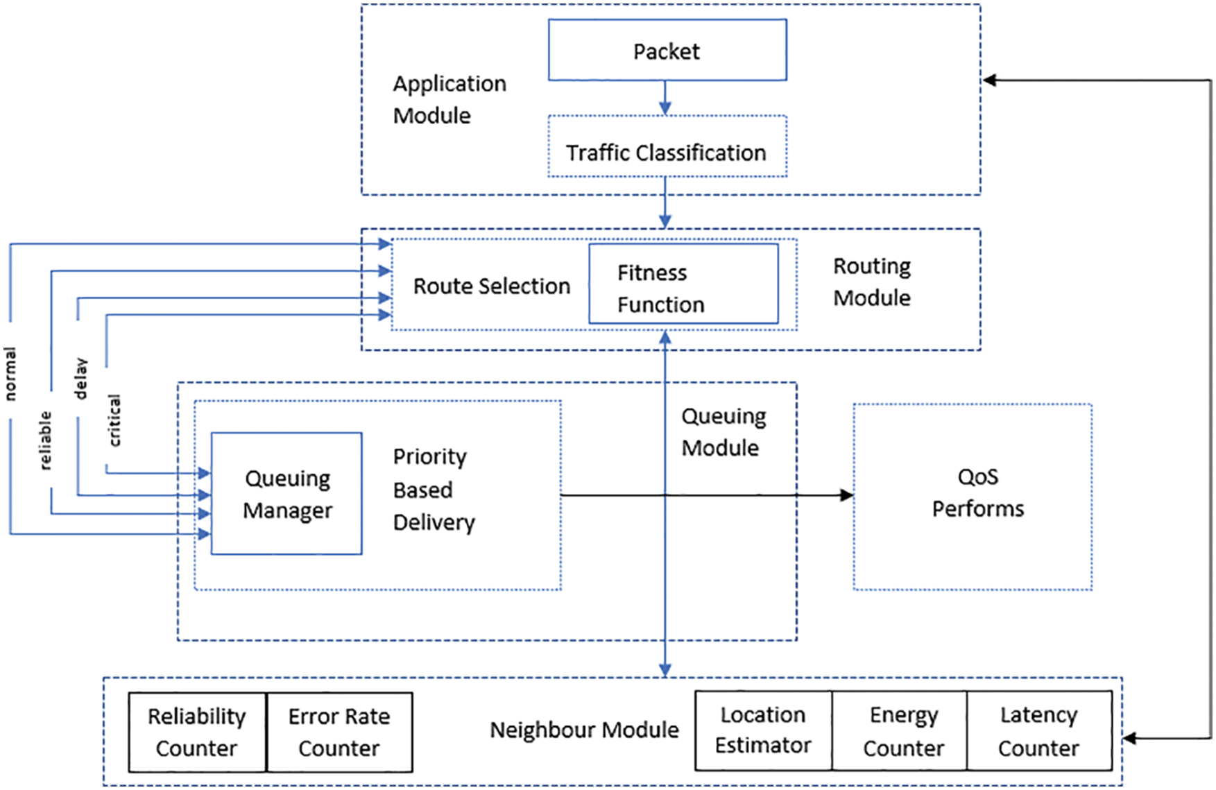
Figure 2: The proposed system architecture
The module, Traffic Classification is accountable for facilitating traffic diversity that focuses on UWSN (Underwater wireless sensor network) applications with various data traffic. This section can segregate the necessary data for each kind of traffic that is based on separating QoS requests corresponding to the data form. It supports customized QoS (Quality of service) metrics for every data form as per the needs. The suggested algorithm can fulfill data-related QoS metrics by employing this kind of classification. Through this, each sensor can map the packet to a different type to a certain group. This enables the algorithm to satisfy the requirement of different QoS services. This kind of traffic classification affects directly the performance of the network in general as it needs to ensure the necessary QoS for every data packet. Output from the traffic classification is used by the FF (Fitness Function) function to allow the route selection depending on QoS purposes like packets forwarding, energy, distance, and error rate.
In this paper, we are suggesting a traffic classification standard that depends on QoS requisites as depicted in Fig. 4. It illustrates the classification procedure of traffic in a submerged sensor node. The initial step toward categorization is to verify the class of every packet depending on the size of the packet or the use of the developed UWSNs or rules of classification. The submerged sensor’s port number or the position of the node that connects to particular types of sensing functions are generally examined fields in the packets.
In general, Data traffics are categorized into the below groups:
a. C1 → Massive real-time traffic which needs consistency and fewer delay facilities as it is connected to the crucial tasks.
b. C2 → Scalar real-time traffic which provides data packets within a given time limit for packet arrival at the Endpoint.
c. C3 → Scalar non-real-time data traffic that needs distribution with no particular time limit, which ensures a fair loss of packets, such as permanent monitoring systems; and
d. C4 → Good effort traffic which does not have any certain conditions.
In the below table, Table 1 describes the traffic kinds that I suggest for standard applications in UWSNs as explained before.
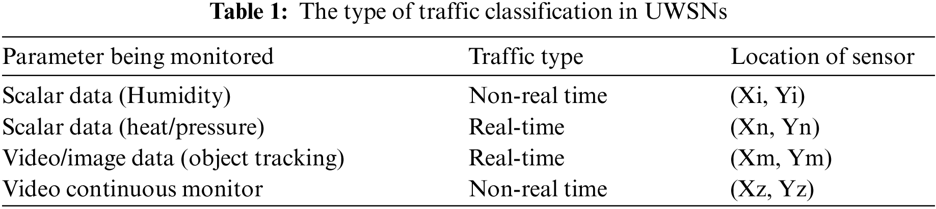
Data cataloging may resolve the necessity of multiple applications in UWSNs (Underwater wireless sensor network) due to the rising growth of many sensing abilities for many observing and data collecting activities. These activities have multiple requirements and significances corresponding to their QoS (Quality of services) related to timeliness, consistency, and power consumption.
3.3 FF (Fitness Function) and Weight
The FF contemplates 5 QoS attributes as given below.
where
When a node is closer to its destination; the hop delay predicted also will be less. It makes the node more attractive for transmitting real-time data.
The below Table 2 displays that traffic of every class is allocated different weights due to various degrees of the significance of each metric.
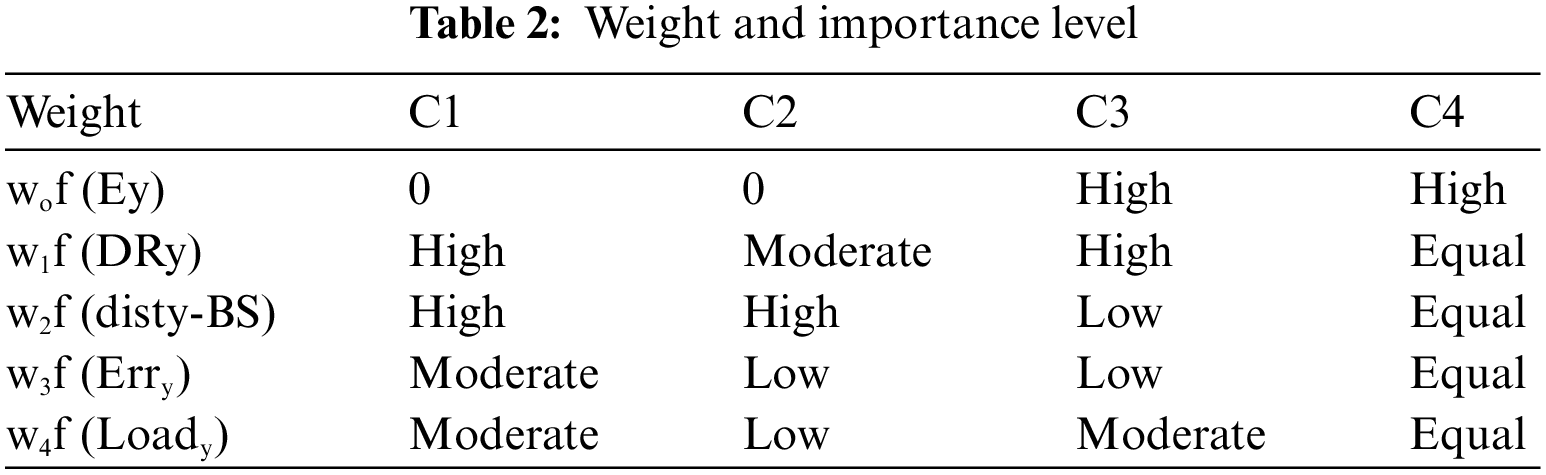
The total weighting factors are 1. According to the above table, we can specify separate weights based on the type of traffic class to each metric depending on the metric’s contribution level. This empowers the FF (Fitness function) methodology to accomplish route classification which fulfills several QoS routes for every traffic class.
As explained earlier, corresponding to data classification we define those different types of data packets that need different degrees of quality and significance and consequently might have different priorities in terms of data routing. Certain applications may require that Destination receives the data packets without any loss, others may be accepting data with the loss of some packets and the rest may accept the delivery within a provided time limit (delay-sensitive). Each packet type, to comply with different QoS according to a variety of data classes, is allocated a specific priority and each packet type is handled differently according to the given priority to meet the application’s needs.
Our class-based queuing protocol depends on the data packet’s priority classified into the below types:
Real-time queue
Non-Real-time queue.
Incoming packets’ type is checked by the classifier, then the data packets are categorized correctly in the upper layer. As per the label, the packets are forwarded into the proper queue. The packets which are having a deadline like C1 or C2 are assigned maximum priority and routed to the real-time queue. At the same time, the packets like C3 or C4 are handled through the non-real-time queue. The implementation along with a packet scheduler shown in Fig. 3 decides the data packet’s order in which the packets are sent to the queue. The order is decided as per the priority of queuing policy depending on each type of packet.
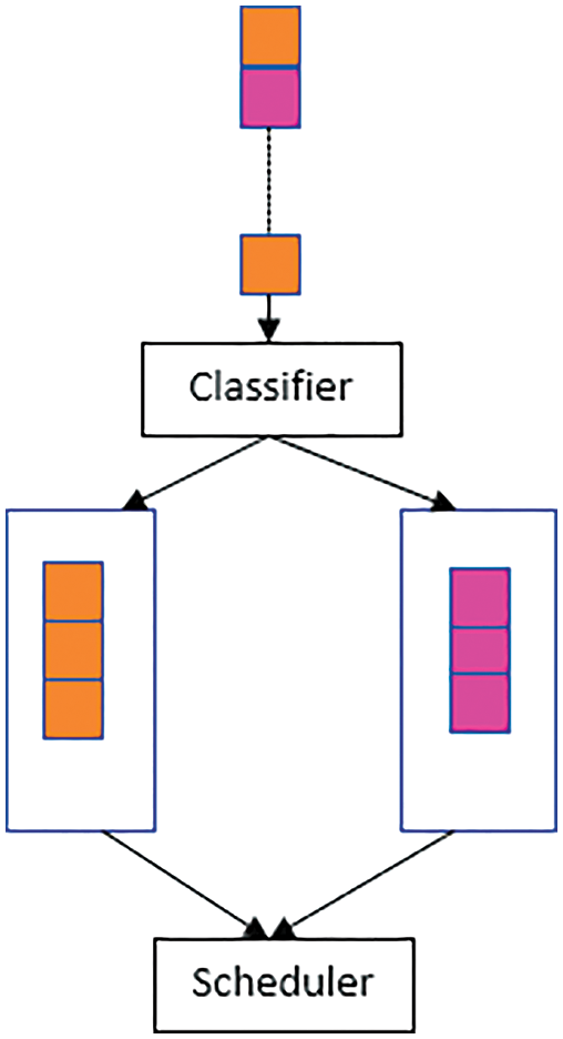
Figure 3: Traffic classification model
Assume this is the threshold of every queue size in which the newly arriving data packets are held. Take x as the priority in a queue for node P, then the queue may keep,
A packet M entering into the ith queue (
As explained in the given formula it’s clear that data packet transmission is determined by the queue classifier by following the priority order of the packets. The critical/highest priority data packets are allotted to C1, after that to C2, afterward C3, and then the last low priority to C4. As outlined in Fig. 5, the queuing model offers some queue size for each type of packet to be held, consequently retaining the throughput for each data class. When one of the two types of traffic is under the limits or non-existent, then both classes can make use of the available bandwidth from each other. Same as the service rate policy, the queuing standard permits a specific type of packet to accept another buffer occupancy, which is committed to different traffic types when the certain buffer is not used or is below the thresholds.
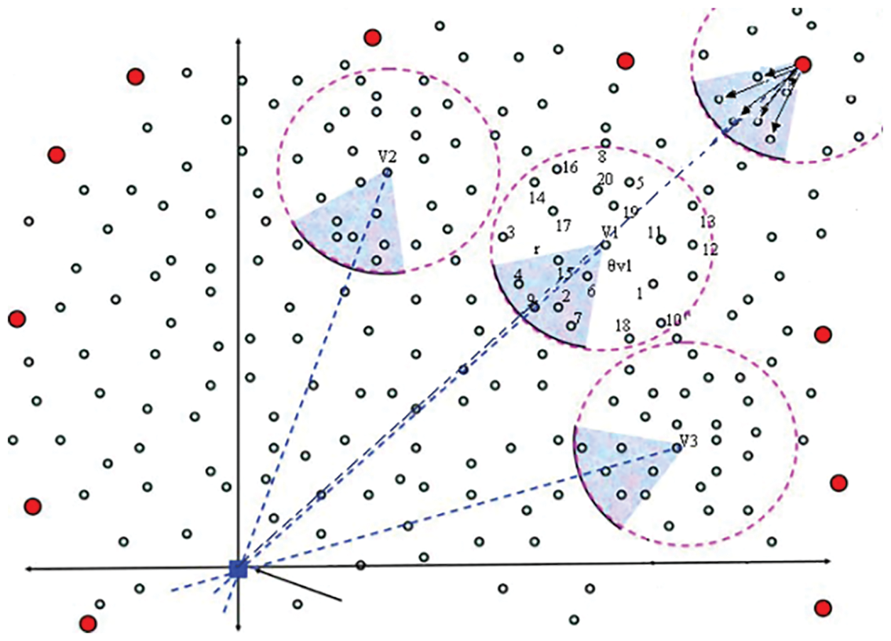
Figure 4: Typical UWS
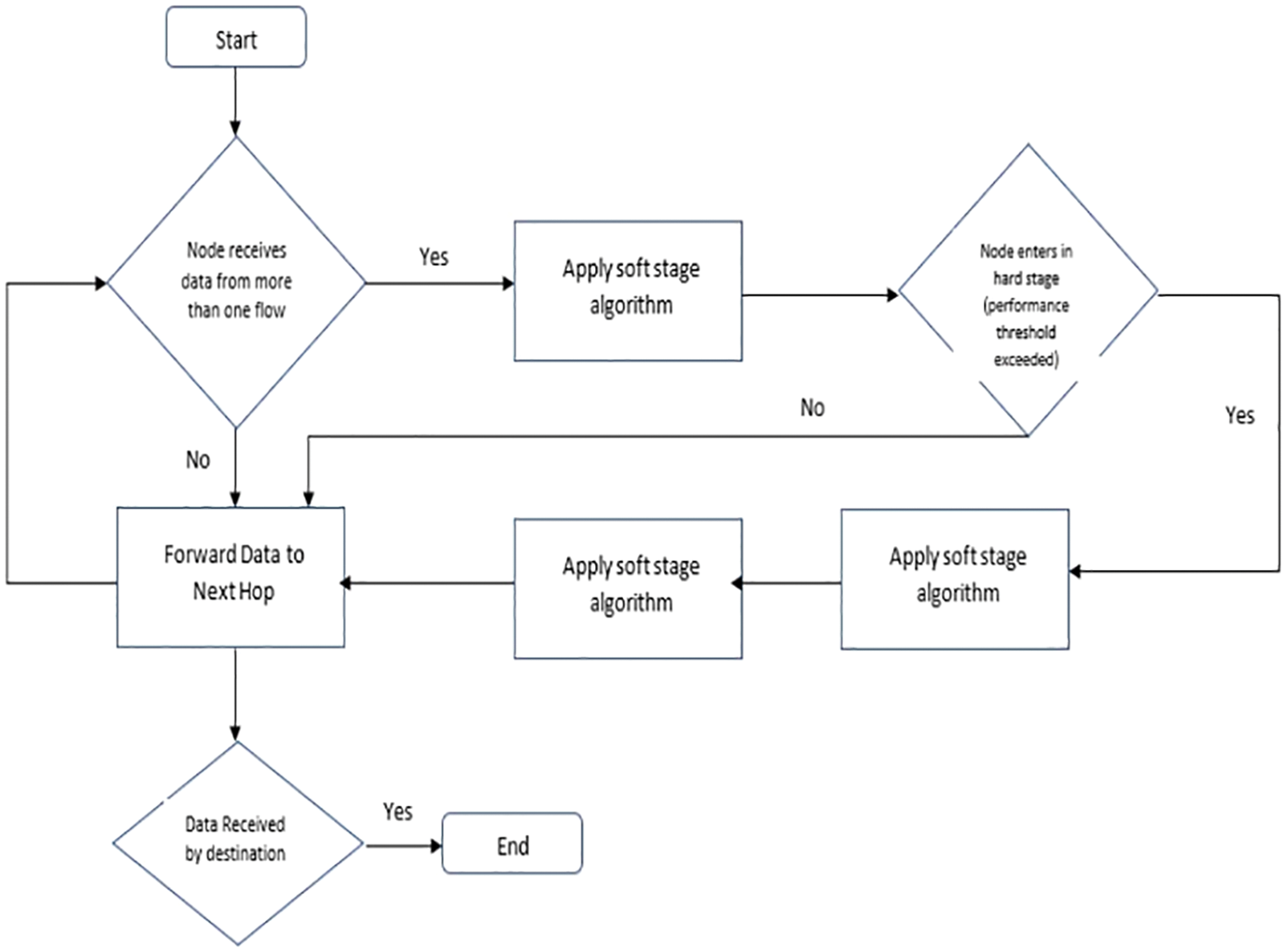
Figure 5: Flowchart of the congestion control algorithm
5 Angle-Based Localization Error Minimization and Routing
In UWSN, energy is used for communication processes, incorporation, and data processing. However, the amount of energy needed for communication is the greatest. Consequently, a great deal of attention has been given to decreasing communication overheads in UWSN (Underwater wireless sensor network) by deploying an energy-efficient routing protocol. To attain robustness in the transmission of data between source and destination nodes, there must be numerous corridors. If all traffic is routed through a minimum energy path, the nodes will be aligned with this path, and energy resources will be depleted thus quickly rendering other nodes ineffective in terms of the network partition even though they can access energy resources. Instead of minimizing the total amount of energy used on a path, the attached network should be preserved for as long as possible.
Path Discovery
Wireless underwater sensor networks may contain a huge number of underwater sensors and these underwater sensors might have different applications. The sink is usually at the center and the UW detector nodes are deployed in an area to observe the surroundings and send some information to the surface sink. These UW (Underwater) detectors have multiple tasks. It senses data and also routes the data to be delivered. The source node detects the event and forwards it to its neighbor and the neighbor forwards it to its neighbor until it reaches the sink. In the proposed protocol the sink will broadcast a hello message to all networks. Every node will save the coordinate of the sink and will broadcast the message with its coordinates. By the end of this process, all nodes will have the coordinates of the sink and their neighbors and the counts of jumps to reach the sink.
The proposed algorithm needs every underwater detector to make a router group using local nearby nodes. The routing angle provides an angle with the network administrator and so limits the number of route path constructions and so reduces the latency as well as packet dispatch time. The construction of a greater number of paths regularly at the period of routing the message with the router sets for balancing the loads, limits the end-end data dispatch time delay. When there occurs any damage to any of the sensors underwater, the ADPC chooses a different underwater sensor from the leftover numbers in the group to get recovered from the damage, increasing the reliability of the data communication without any delay in dispatch.
Fig. 4 shows underwater sensor nodes and base station. The underwater sensor nodes are source nodes (S) and intermediate nodes (V). The
Definitions: neighbors nodes
I.e., in image 3, a group of neighbors nodes
Through way (L): The unstoppable or straight way(L), denoted as (L)
The angle of forwarding by network administrator (
6 Congestion Control and Avoidance
Data traffic plays an important role in all wireless systems. They cause some consequences in the rate of loss, the standard of channels, Usage of connection, the transgression numbers, congestion flow, system feasibility period, detain period, and power along with the output results. So we need to rely upon a perfect scheme for reduced traffic. To overcome these issues, the proposed work utilizes angle based forwarding scheme and we choose the shortest path to the destination using the fitness function which is calculated based on packets routing, false ratio, power, and displacement among the nodes and along with that here we concern upon the congestion conscious forwarding using stage and soft stage scheme will reduce the congestion by monitoring the status of the energy and buffer of the nodes and control the traffic. The flowchart of the proposed scheme in UWSN is shown in Fig. 5, where the Dynamical Secondary Course Option formula is used to reduce congestion.
A flag is nothing but a field that gets attached to the table which only takes the Boolean expressions to point out the presence of the node. The flag scheme gets briefly analyzed and explained during the hard stage scheme.
A tie-break execution method has been presented in this suggested method in the adjacent jump options of the nodes. For example, when a node got in the nearby table, more than one node which is of the same level then it selects the transferring node during each transmission process with the use of the fitness function. This makes them have a balanced energy intake by each node and so the congestion gets distributed among the nodes thus resulting in best load sharing.
The suggested model gets executed with the use of OOPS (Object Oriented Programming Languages) language and thus accession takes place with the use of an improved multi-purposed QoS forwarding scheme. The differentiation between the suggested and the standard model is executed by evaluating the parameters like the mean packet dispatch rate, source-destination detain period, output, and the draining nodes. The simulation takes place on100 –100 m area and highly 200 to 250 nodes are used in 10–10 grid links.
This evaluation takes place on the randomly chosen sensor and surface sink nodes on the normal channel arrangements. The computation objective is to compare the two models of LPQCR (Localization with Priority QoS Congestion Routing) and the ITMIL (Iteration of Mobile Tracing Localization) model nodes selected node distributed in size 100–100 m using NS-3 simulator for traffic sensing methodology for multi-path routing.
The count of packets that gets transferred from the end-end is calculated as the packet dispatch rate. This parameter is used to evaluate the number of packets transmitted from the source node and soundly received at the destination. To get a higher rate value we need to eliminate the trafficking channels as like in a suggested method where they chose the nodes perfectly to get a higher packet dispatch rate. We implemented all four-type traffic packet delivery ratios c1, c2, c3, and c4 is shown in Figs. 6–10 and comparison for four traffic with packet delivery ratios to choose the shortest path to deliver the packets. The below formula gives us the rate values in percentages.
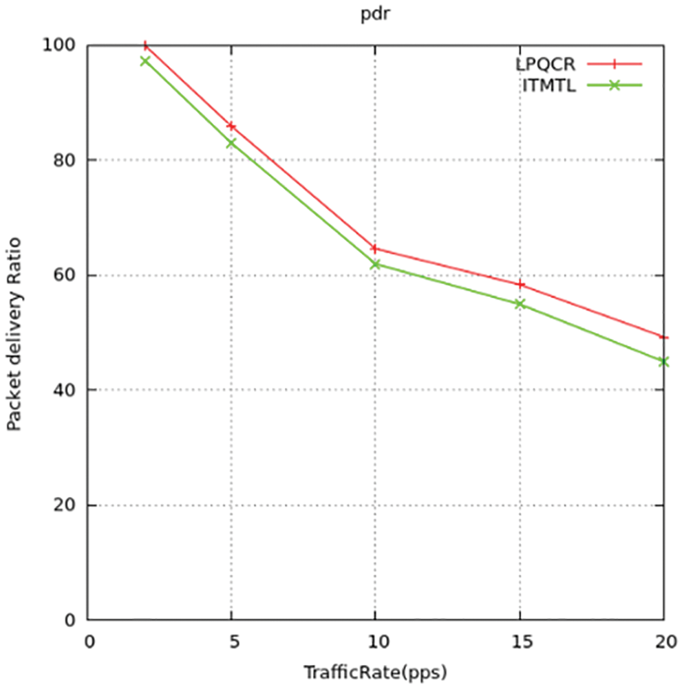
Figure 6: Packet-delivery-ratio-comparison
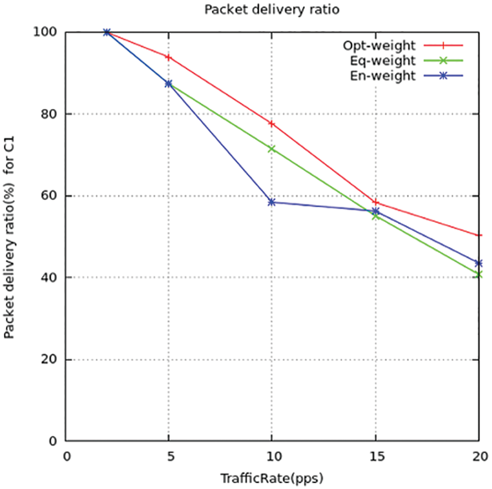
Figure 7: Packet delivery ratio for C1
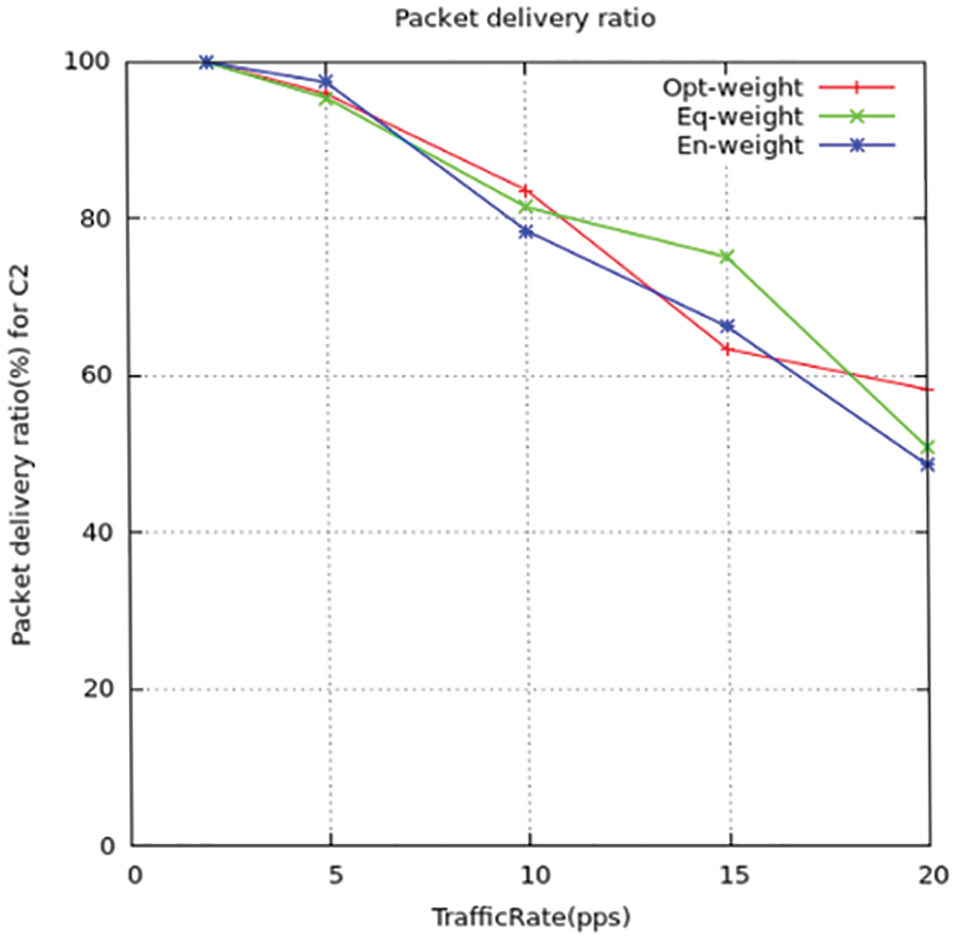
Figure 8: Packet-delivery-ratio for C2
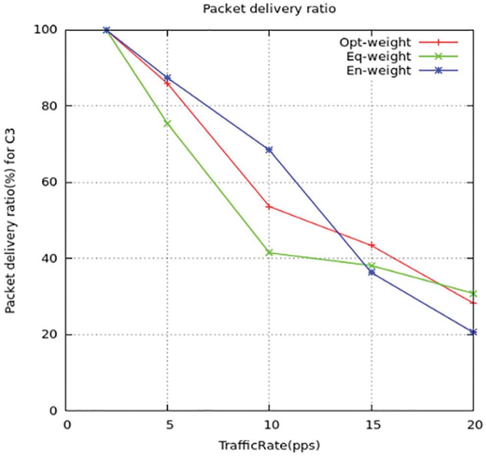
Figure 9: Packet delivery ratio for C3
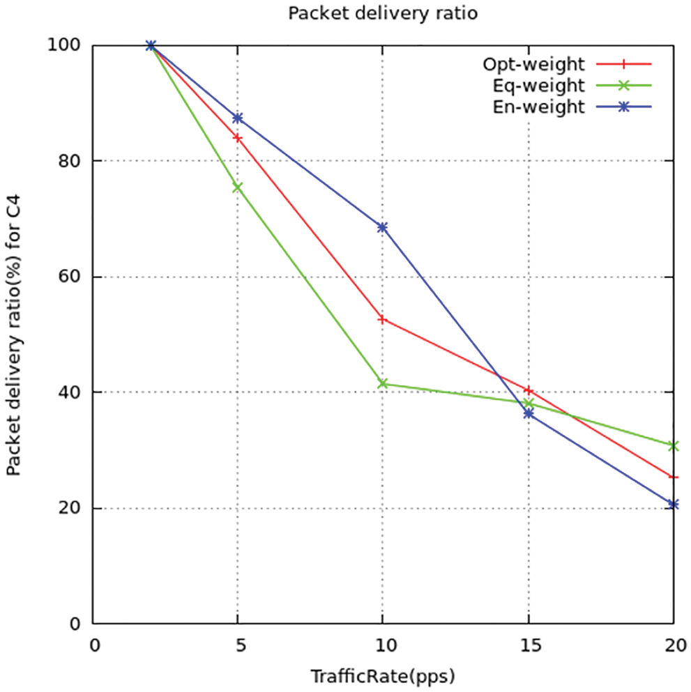
Figure 10: Packet delivery ratio for C4
The differentiation in packet dispatch rate between the suggested method and the standard ITML routing models is shown above in the figures. T find out the rate value they computed the congestion ratio using simulation to detect the effect on the packet dispatch ratio. The output gives the relation as when there is an increase in congestion ratio there the packet dispatch rate is reduced. While the ITML model, they do not take concern the nodes trafficking which affects the working of the model. It results in the wrong selection of nodes for transmission of data and increases the dispatch ratio of the packets to be maximized. Thus, the suggested model LPQCR works well compared to the above-mentioned scheme (ITMTL).
7.2.2 Source-Destination Delay
The congestion in the system can be eased using detain-conscious channel direction and equality. These mentioned parameters could make the dispatch rate higher and thus minimizes the source-destination detain period in the system. We implemented all four types of traffic packet rate delays c1, c2, c3, and c4 is shown in Figs. 11–14 and comparison for four traffic with delays to choose the shortest path to deliver the packets. The mean source-sink delay can be computed using the below-given formula.
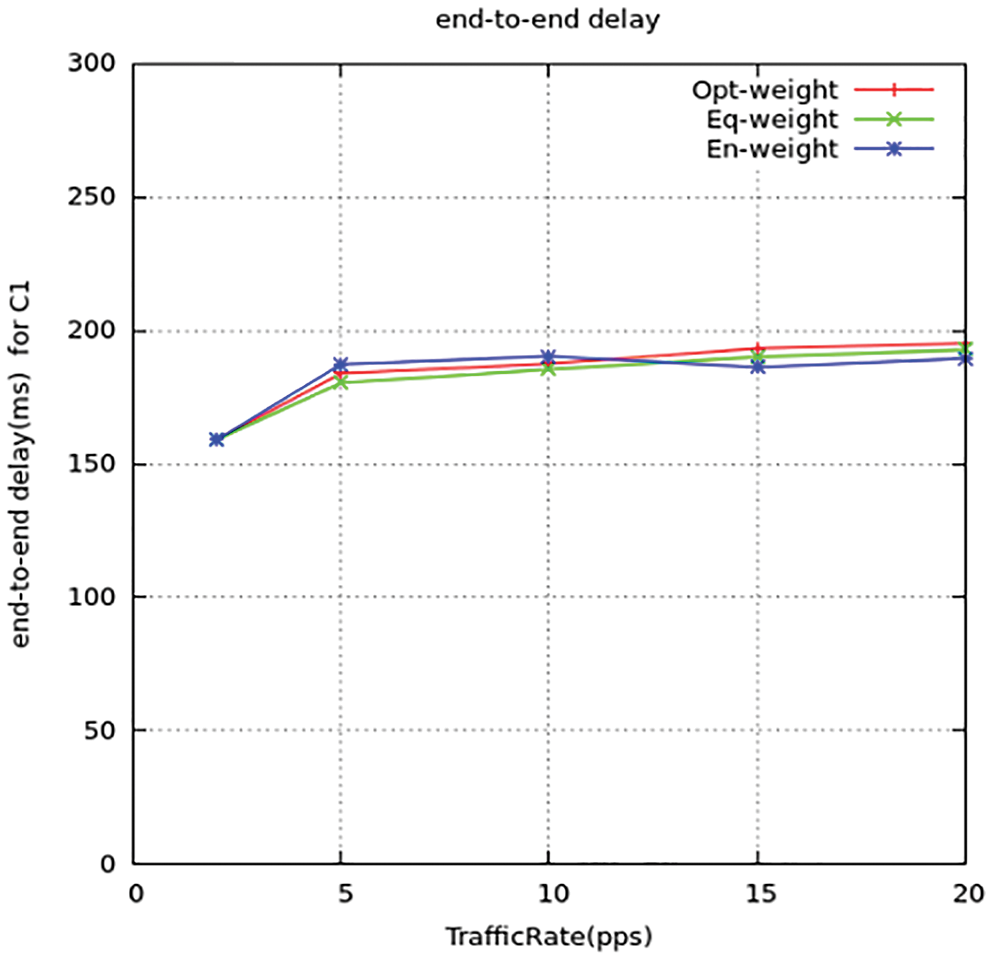
Figure 11: Source-destination delay for C1
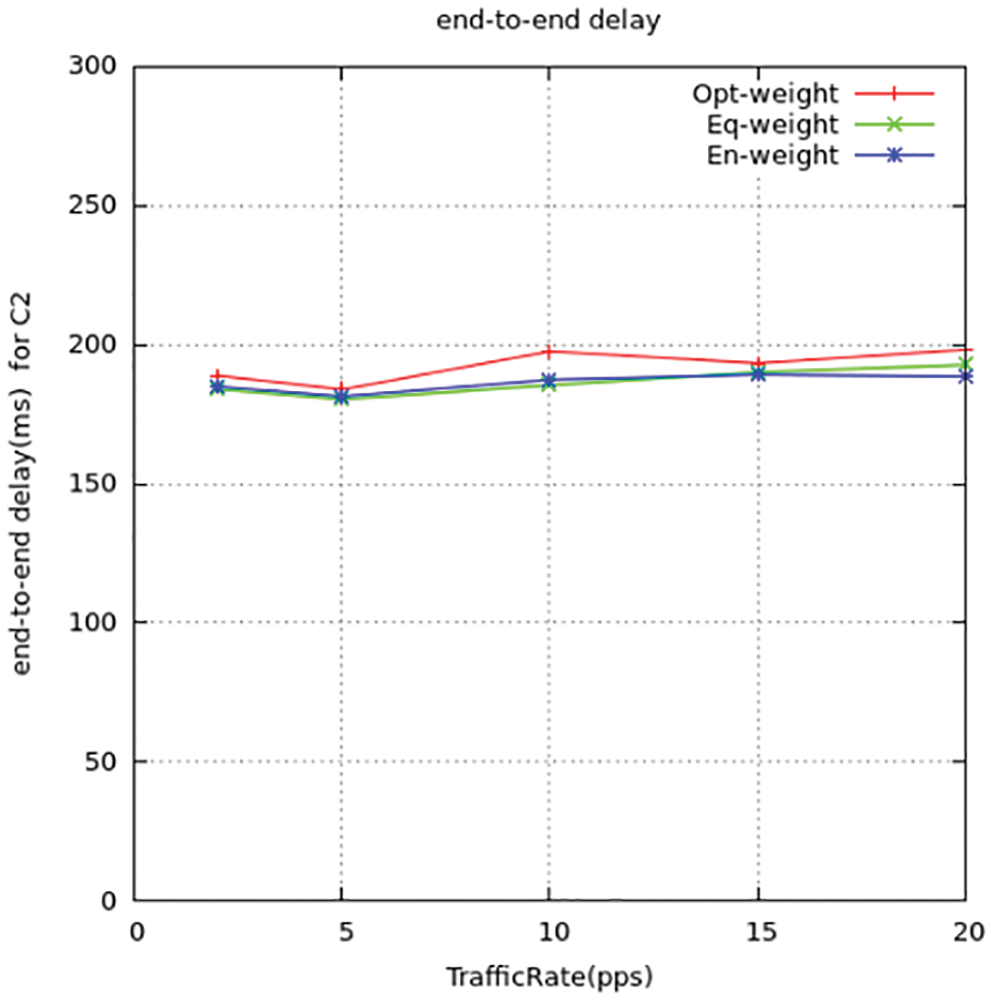
Figure 12: Source-destination delay for C2
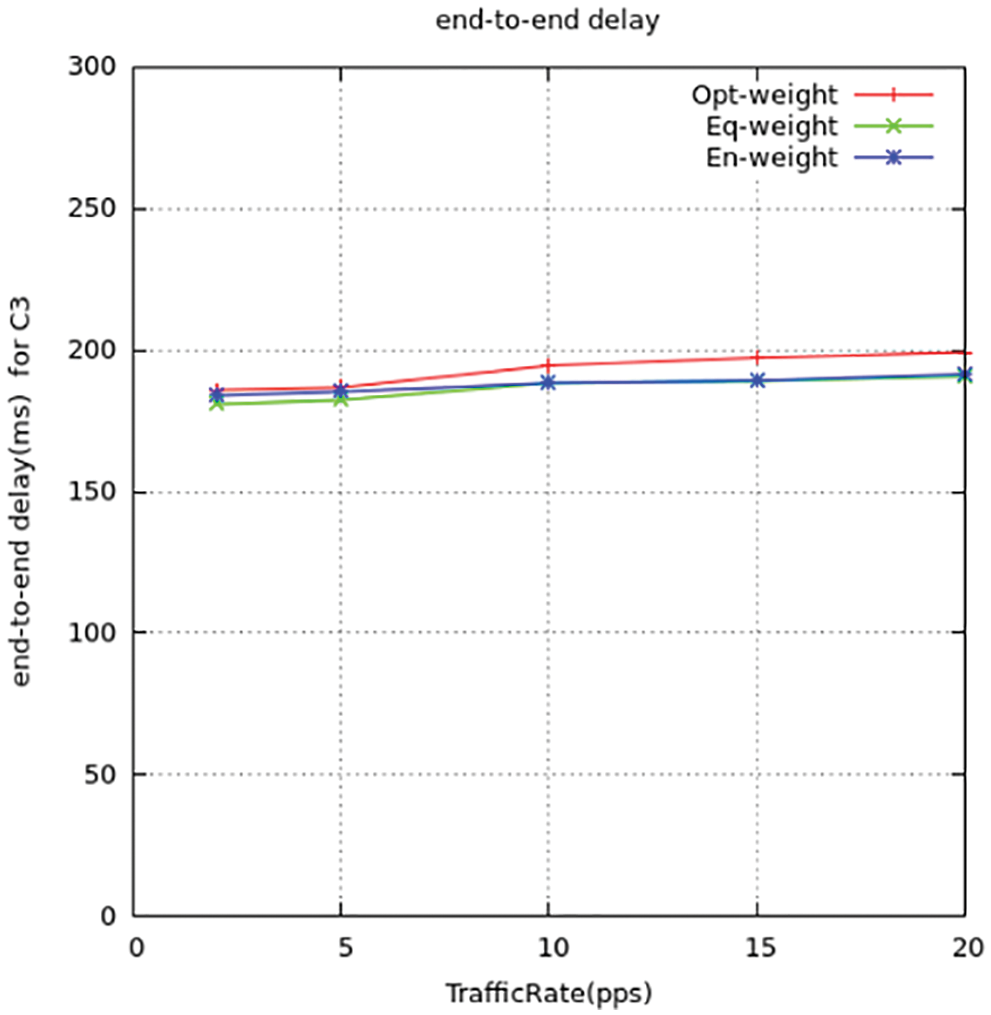
Figure 13: Source-destination delay for C3
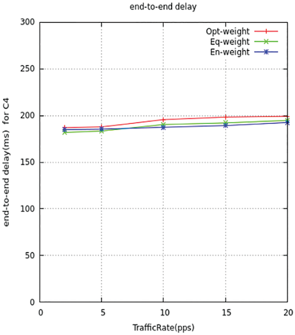
Figure 14: Source-destination delay for C4
Figs. 15 and 16 represent the mean latency detain of the information arrangement. Since the detain period gets direct relativity with the congestion ratio, therefore when the ratio gets maximum leads to over traffic. This results in maximum detain queuing time between the nodes. Thus, it concludes that the low trafficking way reduces the detain time and makes it perform at a better latency period compared to ITMTL.
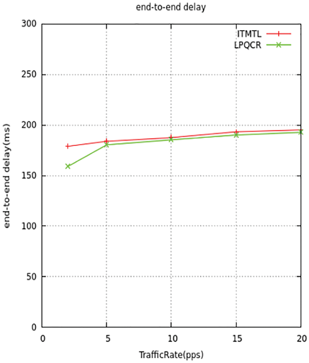
Figure 15: End-to-end delay comparison
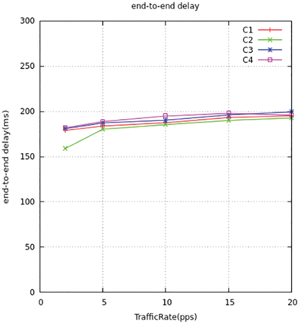
Figure 16: End-to-end delay for all traffic comparison
The Output in the proposed model computes the amount of KB transmitted in a second. The images below display the output differentiation of explained model with the standard models. The output will be maximized under the dispatched bytes to the respective output location, which improves the usage of channels. The suggested model dispatches maximum packets to the endpoint when compared to the standard models. We implemented all four types of traffic throughput c1, c2, c3, and c4 is shown in Figs. 17 and 18 and comparison for four traffic with throughput to choose the shortest path to deliver the packets Throughput is measured by
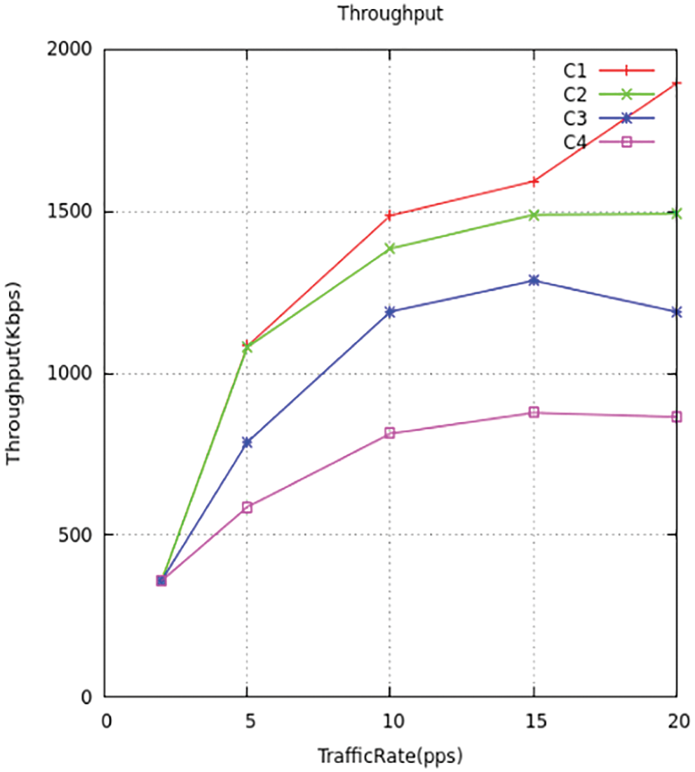
Figure 17: Throughput traffic comparison
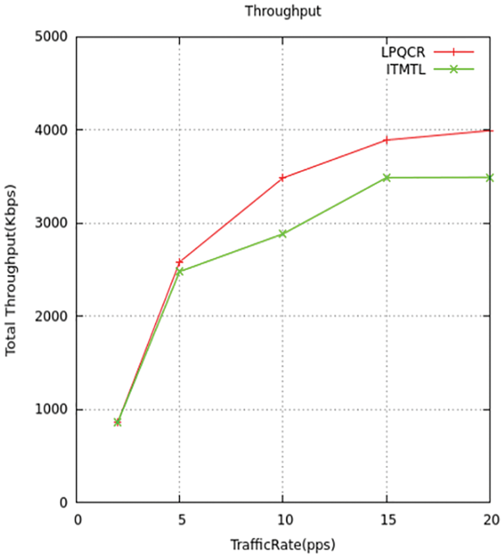
Figure 18: Throughput comparison
The aquatic SNs whose nodes are installed unnecessarily, so there needs to be only a smaller number of nodes. The next stage with the decentralized algorithm in the web inquires the system and checks for switches putting back it again to the same position. We implemented low drained nodes when compared to the existing method. The Figs. 19 and 20 displays the difference between the novel and standard models.
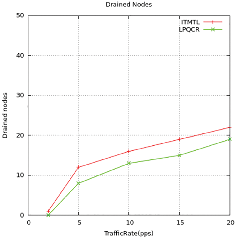
Figure 19: Drained nodes comparison
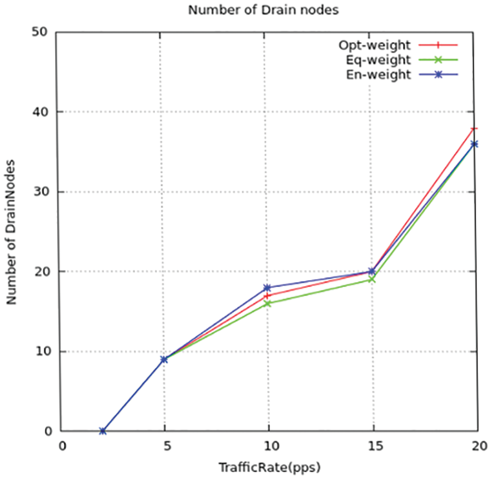
Figure 20: Drained nodes for all traffic
This proposed paper gives the precedence-based Multifaceted QoS traffic control forwarding arrangement that can be applied to many acoustic wireless detectors undersea. It aids the mentioned congestion classes of high-precedence and low precedence. Among them, the high preceded one needs to be taken good care on transmitting the packets carefully without any losses and delays in dispatch and that are employed on delicate and highly important traffic like transferring data using detectors in sea boundaries of the countries. But the other one that gets produced by the detectors for observing the undersea surroundings. A novel traffic control helps to minimize trafficking. The above-explained way of trafficking makes use of an angle-based routing structure for avoiding, sensing, and justifying the trafficking. Assigning similar weights for the nodes may result in incorrect conclusions because of their difference in areas that are located, the proposed hard stage and soft stage scheme which reduce the congestion by monitoring the status of the energy and buffer of the nodes and controlling the traffic. The calculation in the model is done using an NS-3 simulator on different states of performance The various variables were measured like case dip range, case dispatch rate, output or capacity as well as detain using the proposed architecture, and thus the measured variables get differentiated while compared to the existing methods in increased dispatch rate, power effective and their feasibility for a very long period under network-connected QoS variables.
Acknowledgement: This work is supported by Dr. C. Gomathy, SRM Institute of Science and Technology. We would also like thank to the SRM Institute of Science and Technology, Vadapalani.
Funding Statement: The authors received no special funding for this study.
Conflicts of Interest: The authors declare that they have no conflicts of interest to report regarding the present study.
References
1. R. Manjula, B. Sunilkumar and S. Manvi, “Issues in underwater acoustic sensor networks,” International Journal of Computer and Electrical Engineering, vol. 1, pp. 101–110, 2011. [Google Scholar]
2. S. Ahmed, N. Javaid, S. Shahid, F. Hadi and M. Q. Azeem, “RACE: Reliability and adaptive cooperation for efficient underwater sensor networks,” in IEEE Int. Conf. Open-Source Systems & Technologies (ICOSST), pp. 122–128, 2016. [Google Scholar]
3. S. Ahmed, N. Javaid, F. A. Khan, M. M. Sandhu, M. Y. Durrani et al., “Co-UWSN: Cooperative energy-efficient protocol for underwater WSNs,” International Journal of Distributed Sensor Networks, vol. 11, no. 4, pp. 75, 2015. [Google Scholar]
4. S. Ahmed, M. Akbar, R. Ullah, S. Ahmed, M. Raza et al., “ARCUN: Analytical approach towards reliability with cooperation for underwater WSNs,” Procedia Computer Science, vol. 52, pp. 576–583, 2017. [Google Scholar]
5. S. Jain, S. Pilli, M. C. Govil and D. V. Rao, “Performance evaluation of congestion-aware routing protocols for underwater sensor networks with multimedia data,” In Underwater Technology (UT), vol. 1, pp. 1–6, 2015. [Google Scholar]
6. D. M. Carmen, “Marine communities-based congestion control in underwater wireless sensor networks,” Information Sciences, vol. 228, pp. 203–221, 2017. [Google Scholar]
7. Z. A. Khan, O. AbdulKarim and S. Abbas, “Q-learning based energy-efficient and void avoidance routing protocol for underwater acoustic sensor networks,” Computer Networks, vol. 197, pp. 108309, 2021. [Google Scholar]
8. S. Jain, S. Pilli, S. Emmanuel, M. C. Govil and D. Vijay, “Performance evaluation of congestion-aware routing protocols for underwater sensor networks with multimedia data,” in IEEE Int. Symp. on Underwater Technology, pp. 1–6, 2020. [Google Scholar]
9. Z. Zhou, B. Yao, R. Xing, L. Shu and S. Bu, “E-Carp: An energy efficient routing protocol for UWSN on the internet of underwater things,” IEEE Sensors Journal, vol. 16, no. 11, pp. 4072–4082, 2016. [Google Scholar]
10. Y. Teo, Y. Ha and C. Tham, “Interference-minimized multipath routing with congestion control in a wireless sensor network for high-rate streaming,” IEEE Transactions on Mobile Computing”, vol. 7, no. 9, pp. 1124–1137, 2008. [Google Scholar]
11. X. Zhang and M. Zhang, “A high efficient self-organizing network protocol for large scale aware nodes in the internet of things,” in 3rd Int. Conf. on Applied Mechanics and Mechanical Automation, vol. 1, pp. 282–288, 2017. [Google Scholar]
12. W. Rehan, S. Fischer, M. Rehan and M. H. Rehmani, “A comprehensive survey on multichannel routing in wireless sensor networks,” Journal of Network and Computer Applications, vol. 95, pp. 1–25, 2017. [Google Scholar]
13. A. Kha and L. Jenkins, “Undersea wireless sensor network for ocean pollution prevention,” in 3rd Int. Conf. on Communication Systems Software and Middleware and Workshops (COMSWARE’08), Bangalore, India, pp. 2–8, 2008. [Google Scholar]
14. X. Liu, X. Du and Su, “Underwater acoustic networks testbed for ecological monitoring of Qinghai Lake,” in OCEANS 2016, Shanghai, Europe, pp. 1–4, 2016. [Google Scholar]
15. N. Javaid, M. Jafri, S. Ahmed, M. Jamil and Z. A. Khan, “Delay-sensitive routing schemes for underwater acoustic sensor networks,” International Journal Distributed. Sensor Network, vol. 11, pp. 1–13, 2020. [Google Scholar]
16. R. W. L. Coutinho, A. Boukerche, L. M. F. Vieira and A. A. F. Loureiro, “Geographic and opportunistic routing for underwater sensor networks,” IEEE Transaction Computing, vol. 62, no. 2, pp. 548–561, 2016. [Google Scholar]
17. S. Bouk, S. Ahmed, K. Park and Y. Eun, “Energy and depth variance-based opportunistic void avoidance scheme for underwater acoustic sensor networks,” Sensors, vol. 17, pp. 1–16, 2017. [Google Scholar]
18. Y. Noh, U. Lee, S. Lee, P. Wang, J. H. Cui et al., “Hydro cast: Pressure routing for underwater sensor networks,” IEEE Trans. Veh. Technology, vol. 1, pp. 333–347, 2016. [Google Scholar]
19. A. Khasawneh, M. S. B. Latiff, O. Kaiwartya and Chizari, “A reliable energy-efficient pressure-based routing protocol for underwater wireless sensor networks,” Wireless. Network, vol. 24, pp. 2061–2075, 2018. [Google Scholar]
20. M. Nain and N. Goyal, “Localization techniques in underwater wireless sensor network,” in 2021 Int. Conf. on Advanced Computing and Innovative Technologies in Engineering (ICACITE), Noida, India, pp. 747–751, 2021. [Google Scholar]
21. X. Pan, Y. Shen and J. Zhang, “IoT based underwater target localization in the presence of time synchronization attacks,” in IEEE Transactions on Wireless Communications, vol. 20, no. 6, pp. 3958–3973, June 2021. [Google Scholar]
22. S. Kazeminasab, M. Aghashahi, R. Wu and M. K. Banks, “Localization techniques for in-pipe robots in water distribution systems,” in 2020 8th Int. Conf. on Control, Mechatronics and Automation (ICC), Moscow, Russia, pp. 6–11, 2020. [Google Scholar]
23. A. Gunatilake, M. Galea, K. Thiyagarajan, S. Kodagoda, L. Piyathilaka et al., “Using UHF-RFID signals for robot localization inside pipelines,” in 2021 IEEE 16th Conf. on Industrial Electronics and Applications (ICIEA), Chengdu, China, pp. 1109–1114, 2021. [Google Scholar]
24. C. Şışman, S. Sagir and I. Kaya, “Determination of the impact distance applied on long fuel distribution pipes using wireless sensors and lora radio,” in 2021 29th Signal Processing and Communications Applications Conf. (SIU), Istanbul, Turkey, pp. 1–4, 2021. [Google Scholar]
Cite This Article
 Copyright © 2023 The Author(s). Published by Tech Science Press.
This work is licensed under a Creative Commons Attribution 4.0 International License , which permits unrestricted use, distribution, and reproduction in any medium, provided the original work is properly cited.
 Downloads
 Citation Tools