
 Submit a Paper
 Propose a Special lssue
 Open Access
ARTICLE

Efficient Body-Transfer Wheelchair for Assisting Functionally Impaired People
1 Department of Mechanical Engineering, National Taiwan University of Science and Technology, Taipei, 106, Taiwan
2 Center for Cyber-Physical Systems, National Taiwan University of Science and Technology, Taipei, 106, Taiwan
3 Taiwan Building Technology Center, National Taiwan University of Science and Technology, Taipei, 106, Taiwan
* Corresponding Author: Salman Masroor. Email:
Computers, Materials & Continua 2023, 74(3), 4881-4900. https://doi.org/10.32604/cmc.2023.032837
Received 31 May 2022; Accepted 20 September 2022; Issue published 28 December 2022
 View Full Text
 Download PDF
Abstract
Functionally impaired people always have difficulty accomplishing activities of daily living. In this regard, tasks including toileting and bathing have a higher prevalence rate of injuries and greater risk of falling. In this study, a body-transfer wheelchair was developed to assist people in transferring from bed to wheelchair for bathing, and toileting. The body-transfer wheelchair is a semi-automatic wheelchair that has features such as a controlled leg and backrest, linkage commode slot, and height adjustment. The wheelchair consists of a seat and a main frame that can be detached to enable bathtub transfer. This mechanism lets the user stay on the seat while being transferred into the bathtub without any risk of falling. A linkage mechanism was developed as a part of the seat for ease of toileting. Kinematic and force analysis was conducted to calculate the force required for each actuator. It has been proved by the experimental results that the wheelchair can securely and comfortably transfer a patient from the bed to the toilet or bathtub. A survey has been conducted to evaluate the wheelchair prototype design idea. Two focus groups were chosen: one comprised of functionally impaired people, and the other comprised of caregivers. The results of the survey show that 60% of both functionally impaired people and caregivers would like to use the body-transfer wheelchair for toileting and bathing purpose. Additionally, on average 65% of both focus groups find it convenient to operate the body-transfer wheelchair independently.Keywords
As medical care has made significant progress, and the life expectancy of people around the world has subsequently increased, the proportion of the elderly population in the global society is steadily increasing. In 2020, the world’s population of 65 years and over had reached 727 million, and it is estimated that it will double by 2050 [1]. The demographic survey shows that the rate of population aging in countries such as Japan, Singapore, South Korea, and China, is rapidly increasing [2]. In these countries, the dependency ratio of the older population (the ratio of the population over 65 to the population between the ages of 15 and 64) has risen steadily (by 2040, the dependency ratio of the older people in China will exceed 35% [3]. A larger old-age dependency ratio means that there is a shortage of the younger generation, who are traditionally caring for the older members of the family.
Difficulties while performing activities of daily living (ADLs) are key measures of functional impairment in older people. Six standard ADLs identified are moving independently at home, bathing, dressing, toileting, having a meal, and continence [4]. The prevalence of performing ADLs inappropriately is increasing steadily and it is also impacting severely the health and well-being of older adults [5–8]. Problems while accomplishing toileting and bathing tasks, compared with other ADLs, has a higher prevalence among these people [9]. These tasks are most difficult because it involves complex movements of limbs. Considering the case of China, the incidence rate, that is the ratio of people having problems in executing toileting and bathing to the total number of people having difficulty in performing other ADLs over a period of two years, was highest in both males and females [10].
Person transfer assist systems (PTAS) have been developed to aid older people while carrying out toileting and bathing. The utilization of PTAS has proved to be effective in preventing injuries to the caregiver and older people. PTAS has been demonstrated to reduce operational injuries by 43 percent compared to not using it [11,12]. To assist the person in executing the tasks mentioned earlier, hoisting and lifting PTAS are generally used in home and hospital settings [13,14]. For adapting to environmental changes, the Strong Arm has been developed [15,16]. It is an automated robotic arm mounted on the wheelchair base. It has five degrees of freedom and a three-axis load sensor to assist the user in moving from the wheelchair to the toilet commode. The user is hoisted by the robotic arm with a sling for transfer to the toilet commode. The Home Lift Position and Rehabilitation Chair (HLPR), created by the National Institute of Standards and Technology (NIST), is designed to transport, transfer, and rehabilitate patients [17]. The user uses a joystick to control the machine, which promotes independence by enabling autonomous machine-assisted transfers. Another approach used a wheelchair with a lifting function for transferring the user from the wheelchair to the toilet was proposed [18]. The lifting mechanism has a toileting sling, which is driven by an electrically operated winch. The transfer operation starts with hoisting the user with the help of a winch, the seat is removed simultaneously, the caregiver pushes the wheelchair to the toilet from the rear side, and the user is lowered for toileting.
Besides, another form of aid technology was proposed based on the lifting approach [19]. The system includes a multifunctional electric-powered wheelchair, a portable forklift-like mechanism for transferring users, a bathtub composed of a vinyl cloth supported on an aluminum frame, and a portable toilet cleaning mechanism with an autonomous control system. For toileting, a portable toilet is used. However, for bathing purposes, a forklift mechanism lifts the user from the wheelchair and places it in the bathtub. For bathing and toileting, the user must be transferred twice, which increases the injury risk.
Based on the previous discussion, it can be inferred that patient transfer via lifting is a complex task that makes users uncomfortable. It involves a considerable risk of injuries not only for dependent people but also for the caregiver. Furthermore, “Agile Life” introduced a convenient and safer concept of patient transfer called the patient transfer system (PTS). It consists of a wheelchair, capable of a rotatable seat, and a bed, mounted with conveyor belts to deliver and receive the user to and from the wheelchair [20]. The seat of the wheelchair is replaceable, so it can perform the function of a portable toilet. On the contrary, the construction and working mechanism of the system are both intricate and costly.
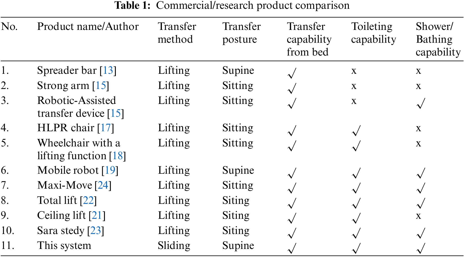
A variety of toilets/bath transfer systems are currently available commercially. Traditionally, toilet slings are mounted on the hoist. These are actuated devices that elevate the user’s weight, usually while the user is hung in a sling [21–23]. Table 1 lists some products and research prototypes that partially meet the requirements of transfer of patient, bathing, and toileting tasks. Thus, it has been analyzed that no transfer system is capable to transfer a person from the bed, toilet, or shower effectively. However, these three tasks are inseparable entities in the daily life of a person with a disability, and an integrated solution is required. Therefore, this research aims to meet all these needs in a better and safer way.
Using a sliding transfer strategy, this study intends to explore the transfer of a person from a bed to a wheelchair, as well as assistance in bathing and toileting concerns. The following are the main challenges we have encountered:
• How to transfer the person from bed to wheelchair without changing the human body, lying on the bed, posture, and angle in the sagittal plane?
• How to develop a mechanism that enables the user to do toileting and bathing by using the same wheelchair for mitigating the multiple transfers and falling hazards?
• How to ensure that the person sitting in the wheelchair should be electrically safe while taking bath?
In this work, the mentioned issues have been addressed, additionally, the finite element analysis using Ansys software is presented. The main contributions of our research work are as under:
We designed a novel wheelchair seat to safely transfer the patient from bed to wheelchair for the purposes of bathing, and toileting.
• We replaced the conventional seat with a soft foam roller to resolve the issue of misalignment of human posture that occurs during the patient transfer from bed to wheelchair.
• The linkage toilet mechanism mounted on the seat enables the patient to do toileting. Moreover, the detachable seat allows the user to perform bathing. Hence, the same chair can be used to perform both operations without the involvement of any additional transfer device.
• There are no exposed electrical components in the design, ensuring zero risks of electrocution in a humid environment. Likewise, there is no risk of falling off the chair.
• Body-transfer wheelchairs ensure minimal involvement of the caregiver in toileting and bathing.
The design concept of our prototype is introduced in Section 2. The mechanical and electronic aspects of the prototype are presented in Section 3. Section 4 shows experimental results that have been conducted to analyze the system performance. The conclusion of this paper is given in Section 5.
2 Design Concept and Mechatronic Aspects of Body-Transfer Wheelchair
Toileting and bathing are the two most important activities for maintaining human health. For the older person and/or disabled, these tasks are difficult to perform independently and safely, and they rely heavily on the presence of caregivers. Therefore, we proposed a system, called a body-transfer wheelchair. The methodology described in Subsection 2.1 considers the basic principles of product design. The process shows how various technologies can be integrated to realize the functionality of the project.
User specifications and design standards are used to develop the body-transfer wheelchair. Since it is an assistive device, it must meet the relevant medical equipment requirements [25]. To ensure that human-machine-interaction is compatible with human dynamics, physiological, and psychological habits, and to ensure that people can use the assistive system to perform various tasks safely, easily, and efficiently. Ergonomic principles are used as another design standard [26]. Therefore, the proposed system was created using these two principles. The backrest, leg rest mechanism, height adjustment mechanism, and toilet mechanism are all part of the mechanical structure. The design scheme of the mechanism is also shown in Fig. 1. The body-transfer wheelchair must accommodate a various range of human body sizes. The wheelchair’s primary specifications were designed using data based on the Chinese adult human body [27,28].
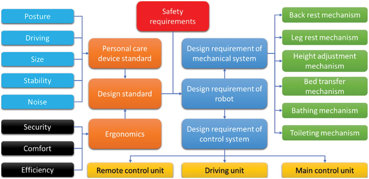
Figure 1: Design scheme of the body-transfer wheelchair
The following section provides a detailed overview of the design of the body transfer wheelchair. While designing the prototype, it has been considered that it has to assist the user in the toilet and shower while reducing the user’s dependence on the nursing staff. To ensure that the user takes a shower and uses the toilet timely, it is essential to move the user from the bed to the toilet chair and vice versa. The body-transfer wheelchair enables the user to be transferred from the bed through a lateral transfer mechanism. It also allows the user to perform the toileting through a linkage mechanism, and the user can be transferred to the bathtub through the extension rail mechanism. The body-transfer wheelchair consists of two main parts. The first part is the mainframe which supports the load of the seat, as shown in Figs. 2a and 2b. Additionally, the three linear actuators for positioning the backrest, adjusting the height, and positioning the leg rest, are shown in Fig. 2a. Figs. 2c and 2d shows the second part of the wheelchair, which is the seat, it consists of soft rollers for ensuring the comfortability of the user. The seat also comprises a toilet linkage mechanism. The noise level of the actuator meets the appropriate noise level standard for medical equipment. Figs. 2e and 2f shows how toileting possible by giving space on the mainframe and the commode slot on the seat.
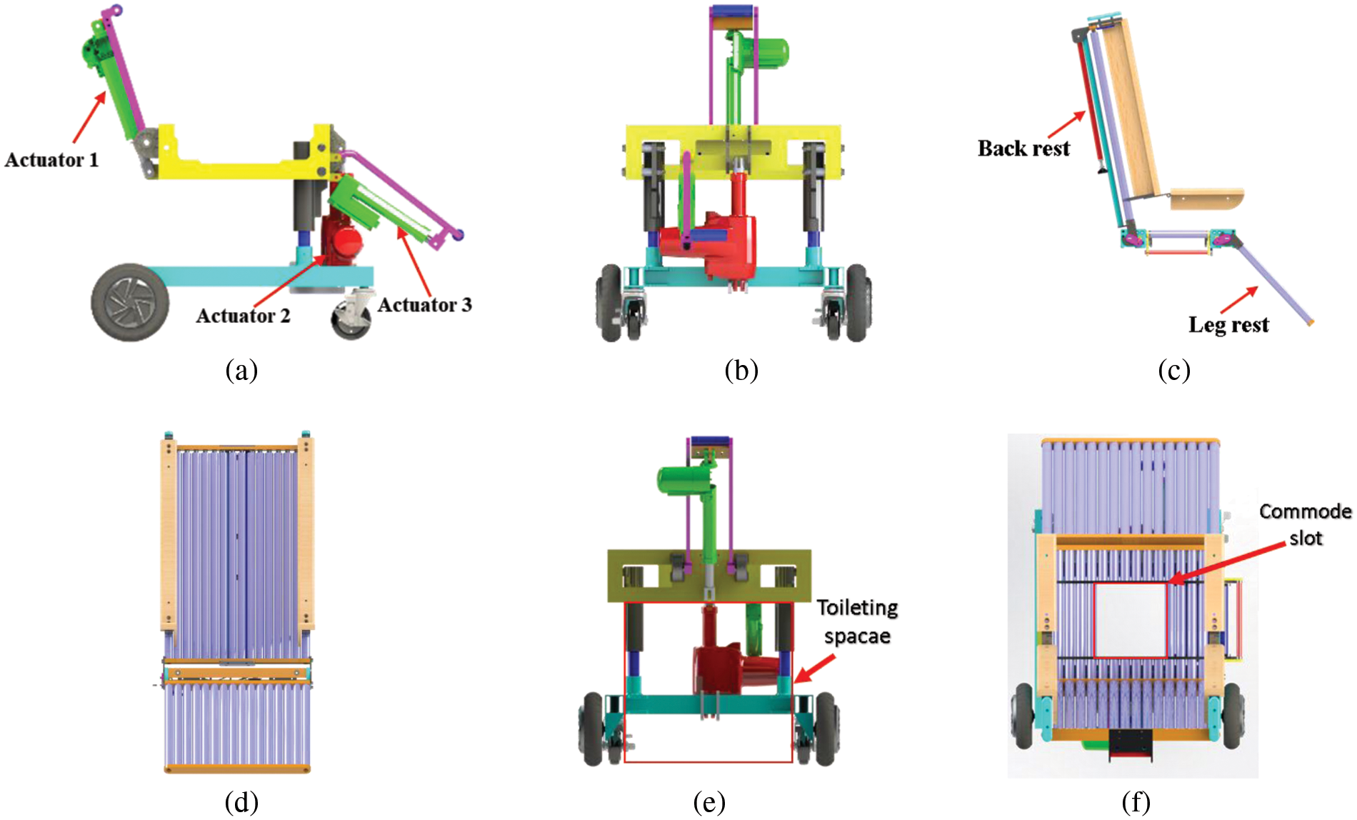
Figure 2: Main part of the body-transfer wheelchair (a) Base frame, side view (b) Base frame, front view (c) Seat, side view (d) Seat, front view (e) Base frame, rear view (f) Commode slot, top view
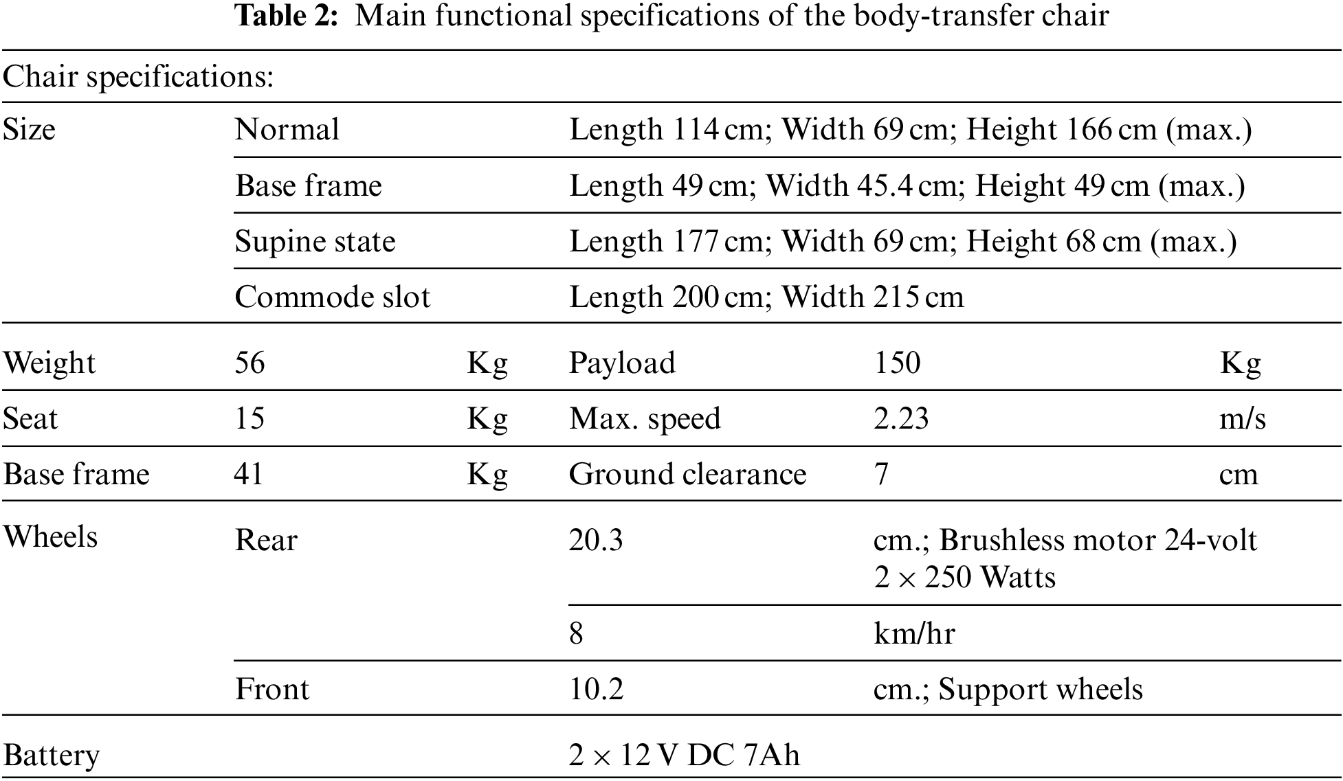
Table 2 is lists the specifications of the body transfer wheelchair. Normal size means the total size of the wheelchair on regular looks. Base frame size is a space beneath the chair that can come over the toilet commode. The supine size represents the total size of the wheelchair seat under the fully reclined state. The commode slot means the area of the seat where the linkage commode mechanism is mounted. The purpose of a wheelchair is to provide comfort and safety to the user, especially while performing bathing. Generally, while using a commercial product, the user always needs to move from their wheelchair to the bathtub for bathing. Most of them do some dangerous maneuvers by themselves or help from their caregivers for transferring them to the bathtub. Therefore, the special bathtub design aims to realize the bathing capability.
The bathtub system has a pair of guide rails, which can accommodate a wheelchair seat, as shown in Figs. 3a and 3b. The design load that the guide rail can bear is 180 kg. The transfer process will be described later in this section. During the transfer process, the seat is detached from the mainframe, and the guide rail is extended, as shown in Figs. 3a and 3b. This guide rail is attached beneath the seat with the help of a locking mechanism mounted underneath the seat, as shown in Figs. 3c and 3d. Before the transfer process starts, the linear actuators 1 and 3 are retracted backward and the interlocking mechanism installed on the seat, locking the seated pose, and maintaining the balance, as shown in Fig. 3e. In all the processes, the user just needs to sit on the seat part. Maneuvers on a wheelchair can be controlled using a controller by the caregiver, and the caregiver should also manage the rail extension operation.
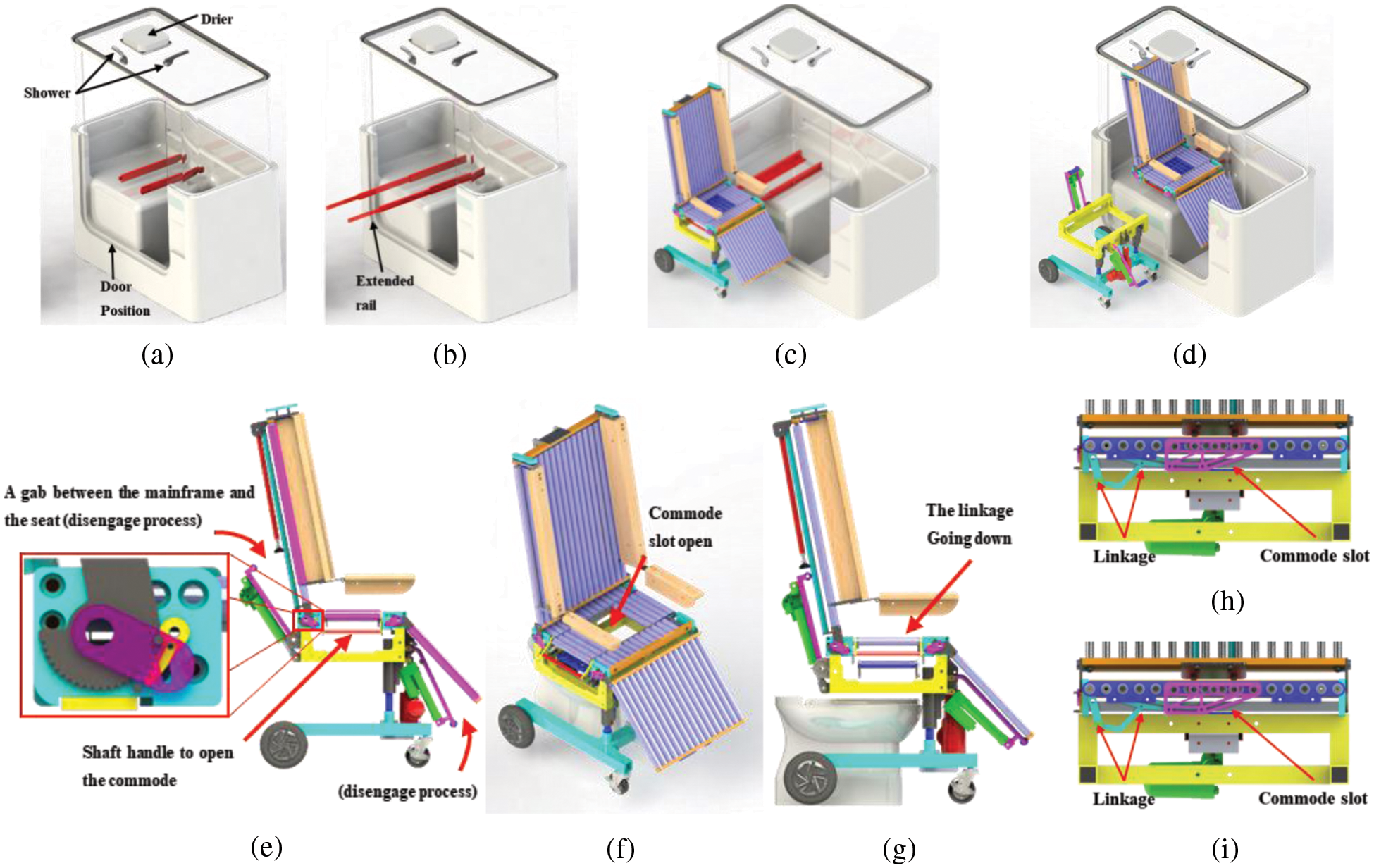
Figure 3: (a) Transfer process to the bathtub, Normal position (b) Extended rail for transferring a person (c) Seat and the rail engage (d) Track shifted the position inside the bathtub (e) Interlocking mechanism. (f) Linkage slot mechanism mounted on the seat for easy toileting, isometric view (g) Approaching toilet, side view (h) Commode slot closed (i) Commode slot open
Fig. 3f shows a simple commode slot mechanism built into the seat that allows the user to do toileting. A shaft handle that can move the marked part (red outline) on the seat underneath it, when the axle handle is pulled as shown in Fig. 3g. The obtained position is in the shape of a commode and has enough space for the user to feel comfortable during defecation. This position can be reached by applying a 4-bar linkage mechanism. The linkage in a closed position by simply pushing the handle forward as shown in Fig. 3h and pulling the handle backward will open the commode as shown in Fig. 3i.
Fig. 4a shows an illustration of how the weight distribution acts on the seat. The rotation happens on the backrest and leg rest, and it is used to calculate forces to define the actuator payload requirements. Kinematic analysis is used to calculate actuator specifications. The moments are acting on the backrest and leg rest, having a similar free-body diagram, as shown in Fig. 4b. W1 Acting on point A is the weight of the seat support structure of the upper limbs and backrest. When W3 Is resting on the leg, W is the weight of the leg and the supporting structure of the leg. The difference between the two is total weight (Wi), length (Li), and rotation angle (α & β). According to the rigid body balance equation [29], the equation can be derived as Eq. (1).
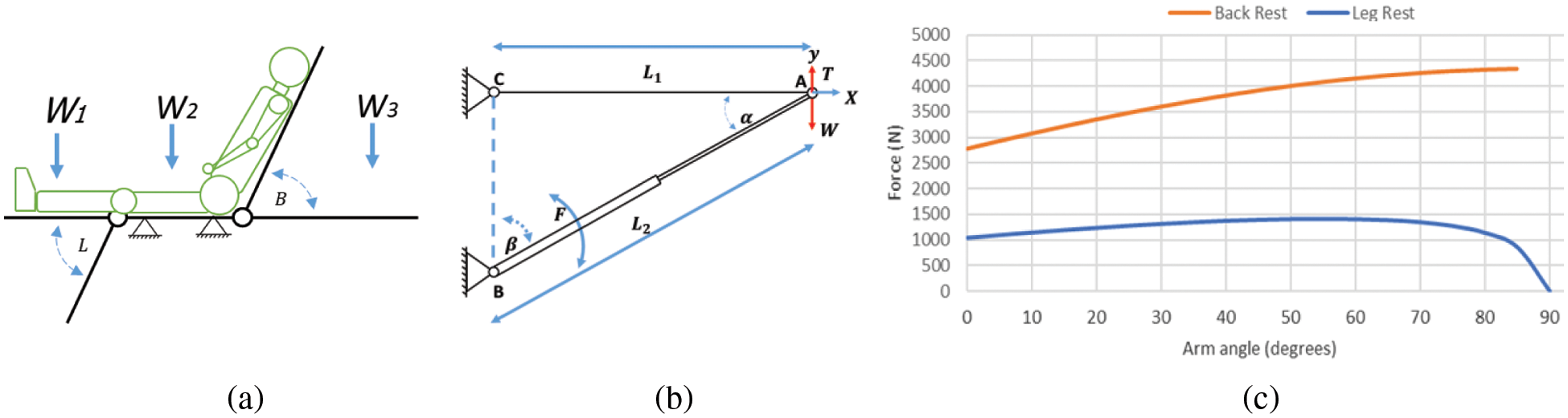
Figure 4: (a) Backrest & leg rest rotation illustration (b) Free body diagram of rotation ether backrest or leg rest (c) Requirement force for backrest & leg rest actuator to a certain degree
Eq. (1) can be derived from the free body diagram expressed in Eq. (2).
The force needed to lift the weight on the backrest and leg rest can be derived from Eq. (2) into Eq. (3).
The average weight of the upper limbs of a person weighing 75 kg is about 40 kg, and the entire backrest structure of a wheelchair is about 8 kg. The backrest actuator should lift the total weight by 48 kg. Based on Eq. (3), the total weight (W) of the backrest structure and the limited rotation angle (α & β), the force required to support the backrest has been calculated, and it is described as the back rest line diagram in Fig. 4c. It has a minimum mandatory value >4.4 kN to lift the upper limbs from the reclining position to the sitting position. Based on this calculation, MD 60 from Moteck was used. It has a maximum of 6 kN (push)/4 kN (pull), the medical standard noise level is
For the leg rest force calculations, the total weight used is 19 kg, including the legs and the structure’s weight. Using the Eq. (3), the force required to lift the leg has been calculated and described as a line graph of the rest of the leg in Fig. 4c. It has a minimum force of >1.5 kN and can lift the legs from a sitting position to a reclining position. Based on this calculation, MD 60 from Moteck was used. Its maximum thrust is 2 kN (Push/Pull), the medical standard noise level is
The height adjuster has a key part that is used to support and lift a total weight of 115 kg, which includes the user’s body and 70% of the weight of the wheelchair to be lifted. The direction of the height adjuster’s loading force is parallel, so the force of lifting the wheelchair will be very stable. According to manufacturing standards, MD 100 linear actuators with the matched static load capacity and lifting force apply to wheelchairs. Its maximum thrust is 10 kN (push)/6 kN (pull), the medical standard noise level is
To predict the possibility of design failure, the most important thing is to conduct a comprehensive structural analysis. The numerical analysis uses the finite element method (FEM) on the 3D solid model to assess structural integrity. The study used ANSYS static analysis to check the base frame’s safety factor. To prevent structural failure caused by static load, repeated load, and fatigue, a minimum safety factor of 5 is required [30]. The mainframe is a vital structure, and its strength should be sufficient to support all seats and the user’s weight. Fig. 5a is a basic frame composed of (1), (2), (3), and (4), representing the upper frame, upper cylinder, lower cylinder, and base frame, respectively. Fig. 5b shows the load Fx On the seat, and the user’s weight is applied to the upper frame, while (A), (B), (C), and (D) are wheel supports. Concerning the geometry of the force direction and the position of the part, a direct force (Fi) and moment (Mi) will be applied to each structure. According to the force and support position, the part numbers (1), (2), and (4) are numerically analyzed. The reason is that the welding process may fail. Part (3) is the standard part of Misumi PSPJ30-275 hardened 52100 bearing steel with a hard chrome surface finish. The yield strength of this standard part is 415 MPa. It is strong enough to withstand the direct forces and moments of the upper structure of the wheelchair. As shown in Fig. 5c, the load uses a person weighing 75 kg and applied a 5-time safety factor. The load is applied in the first step of defining fixed support, material, and load. The top frame uses aluminum 2014-T4 to get minimum weight. Its mass density is 2800 kg/m3, and the yield strength is about 290 Mpa [31]. As shown in Fig. 5a, a force Fz = 1063.8 N is applied to the side of the upper frame. The displacements are fixed at points (A) and (B). The simulation results show that the design and material selection meet the five times safety factor, as shown in Fig. 5b. The results show that the aluminum square tube’s minimum thickness should be 3 mm. Based on this result, a 1.5-inch square tube with a thickness of 3 mm was used.
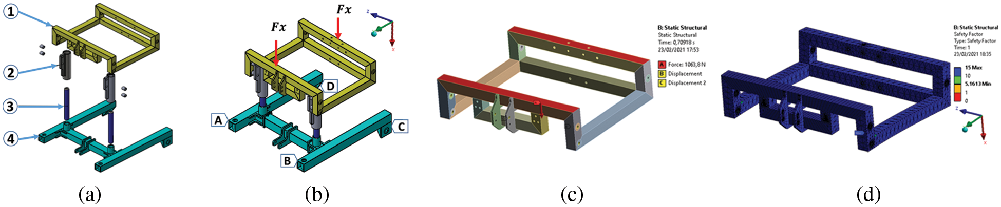
Figure 5: Base frame construction (a) Explodes view (b) Force and support position (c) FEM of the upper frame, defines the load, and support (d) Simulation result
Another part that has been welded is analyzed, namely, the upper cylinder made of aluminum 2014-T4. The moment applied due to the upper frame’s geometry exerts a force at a certain distance relative to the cylinder support. It bears the load Fz = 1.5 kN, My = 600 kNmm, and is placed on the structure shown in Fig. 6a. The simulation results show that the design meets the five times safety factor, as shown in Fig. 6b. The results show that the cylinder’s minimum thickness is ≥6 mm, and the plate thickness is ≥13 mm. The proposed material is Steel AISI 1020 for the base frame. The mass density is about 7900 kg/m3, and the yield strength is about 352 MPa [32]. It bears the load Fy = 2 kN, Mx = 600 kNmm, placed on the structure shown in Fig. 6c. The simulation results in Fig. 6d show that the design and material selection are in line with the safety factor of 5. The results show that the steel square tube’s minimum thickness should be 3.5 mm. Based on this result, a 2-inch square tube with a thickness of 3.5 mm was used.
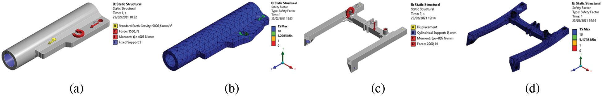
Figure 6: (a) FEM of the cylinder support, define the load, and support (b) Simulation result (c) FEM of the base frame defines the load and supports (d) Simulation result
2.5 Body-Transfer Wheelchair Prototype
The complete assembly of the body transfer wheelchair is shown in Figs. 7a and 7b. No electronic equipment is mounted on the seat to prevent the user from being electrocuted while taking a bath. The rollers on the seat are aluminum cylinders covered with polyurethane foam. Each side of the roller uses metal roller bearings connected by bolts as the seat’s major support. The inner roller uses nylon bearings for better sliding. A commode slot is also created on the seat that can be opened with the help of a handle as depicted in Fig. 7c. The fully supine mode to transfer a patient between the wheelchair and bed is shown in Fig. 7d.
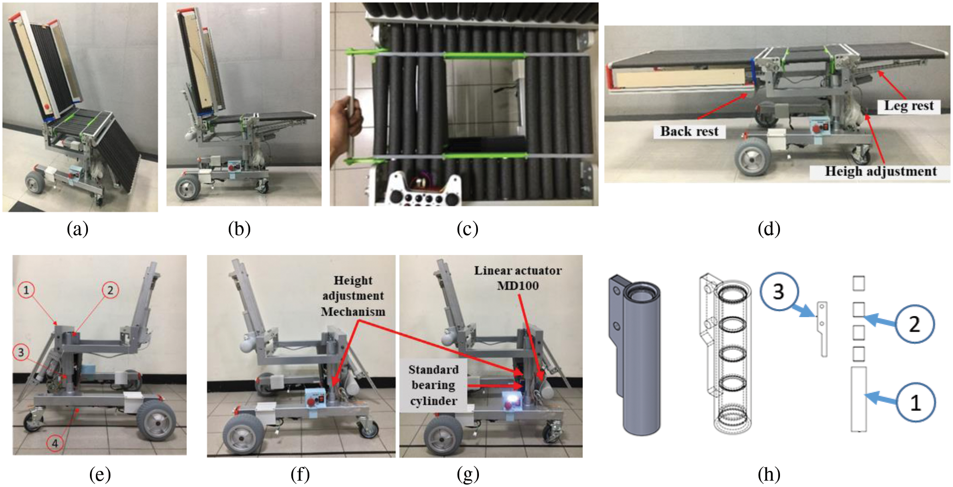
Figure 7: Prototype (a) Isometric view (b) Body-transfer wheelchair in leg support raised condition (c) Commode slot (d) Side barrier rotated to give access for transferring (e) Base frame design and final assembly: (1) Upper frame, (2) Top cylinder, (3) Lower cylinder, and (4) Base frame (f) High adjustment, Lower height (g) Upper height (h) Top sliding cylinder support (explode view)
Fig. 7e represents the base frame and includes three primary mechanisms height adjustment mechanism, a backrest support mechanism, and a leg rest support mechanism driven by a linear actuator has been calculated in Section 2.3. Arch welding is used to coalesce all steel structures, while TIG welding is used to join aluminum parts. For the front wheels, casters with swivel locks are used.
Figs. 7f and 7g represents the height adjustment mechanism on the minimum stroke and maximum stroke respectively. It is designed to help people transfer to the bed, and bathtub and adjust the wheelchair to various commode heights. The total height of the wheelchair while the actuator on the maximum 10 cm retraction. Normally, the speed at no load is 9 mm/s. To give a smooth translation, standard bearing cylinder quality is used for the inner tube as shown in Fig. 7g. Also uses the bushing as the outer cylinder’s sliding surface as shown in Fig. 7h point (2) and Fig. 7h points (1) and (3) are housing for the bushing made from aluminum.
The backrest support is designed to handle the backrest rotation from 0° to ±70° [33,34], as shown in Figs. 8a and 8b. The speed of the actuator at no load is 23 mm/s. There are embedded limit switches inside the actuator to restrict the actuator’s extension and retracted length. By this system, the actuator will stop automatically when the backrest reaches the maximum and minimum degrees. The crane mechanism is applied to minimize the power needed to rotate the backrest compared to direct drive. The additional limit switch attached to the backrest tip can determine whether the roller support is in contact with the backrest support. Fig. 8 shows two square hollow tubes are used to transmit the linear actuator’s power and support the weight of the backrest. The leg rests support is designed to handle leg rest rotation from 180° to 270°, As shown in Figs. 8c and 8d. Mechanically, the leg rest system is similar to the backrest. The differences are the workload and angle limitation. The average speed of the actuator speed is 20.1 mm/s in no-load conditions.
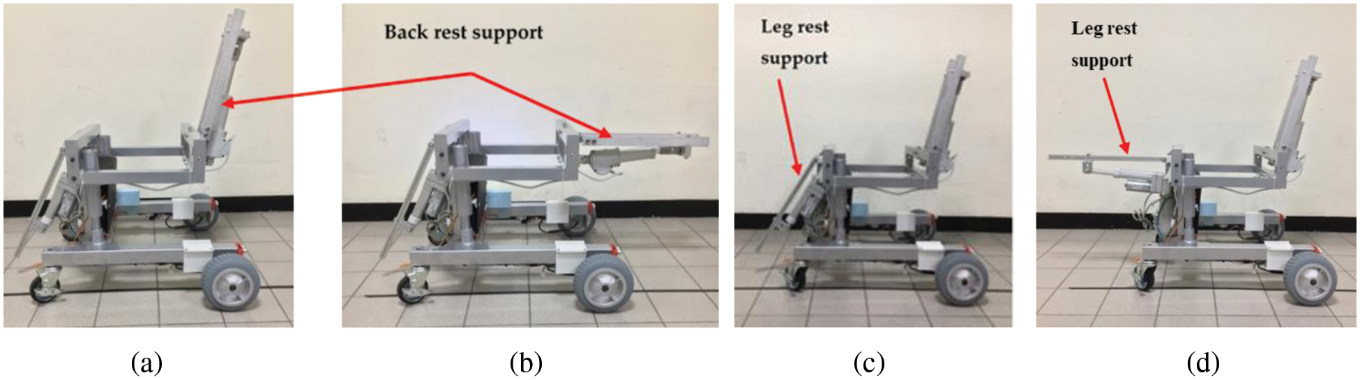
Figure 8: (a) Leg rest support, 70° (b) 0° (c) Leg rest support, 200° (d) 180°
2.6 Electronics and Controller
The electronic schematic diagram is shown in Fig. 9. The upper portion of Fig. 9 shows the arrangement of sensors with the main controller and the lower portion of the figure shows the connectivity of actuators with the controller. This circuit uses Arduino Mega 2560 as the main controller to receive data from various sensors and control all actuators and emergency systems. There are digital and analog systems that are regulated by the controller. Serial communication has been used to connect all the I/O devices. The advantage of using this type of communication is, that it simplifies the wiring between the main controller and the device. For the analog I/O, a voltage divider is used for input, and a DC analog driver such as a relay is used to control actuators. The control architecture and logic are developed on the Arduino IDE [35,36].
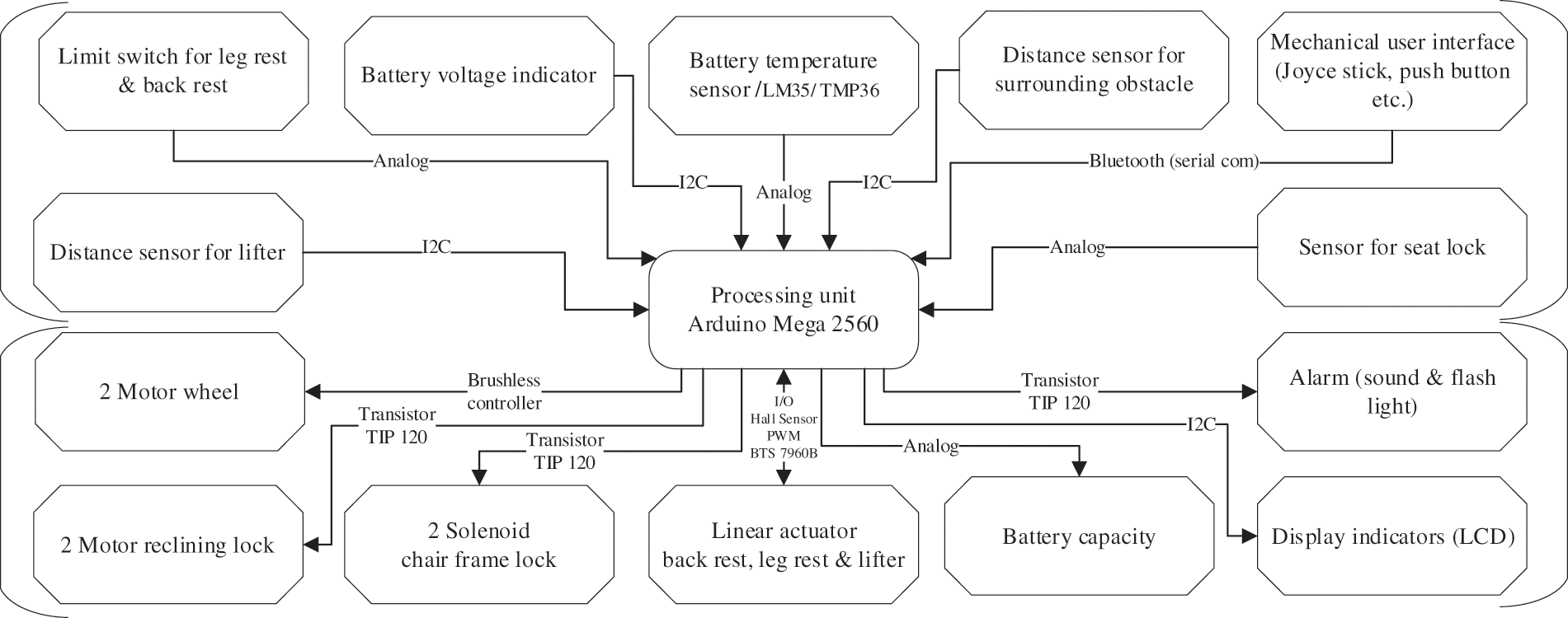
Figure 9: Electronic schematic diagram
3 Experimental Results and Discussion
According to the body transfer wheelchair’s proposed design strategy, the prototype verification is achieved by solving its three essential operations: Firstly, the person is moved from the bed to the wheelchair. Secondly, to help the diagnosed person use the toilet, and lastly to transfer the user from the wheelchair to the bathtub. In both cases, the participation of nursing staff is minimal. The prototype has been tested at the National Taiwan University of Science and Technology (NTUST) in Taiwan. The subject selected for testing the prototype to perform the transfer, toileting, and bathing task was 163 cm tall and weighed 68 kg.
3.1 Case 1: Subject Performing Toileting Process
Getting out of bed is the first step in achieving this goal. Figs. 10a–10f respectively, show the moving sequence of the user from the bed to the wheelchair. The experiment uses a bed equipped with motor-powered conveyor belts, which can move the user from the center of the bed to the bed’s side near the wheelchair. Initially, the caregiver positions the wheelchair to the side of the bed, then with the help of conveyor belts the user moves towards the side, as shown in Figs. 10a and 10b. After approaching the wheelchair, as shown in Fig. 10c, the caregiver helps the user to transfer onto the wheelchair by gently pulling the person’s body, as shown in Fig. 10d. Afterward, the lower body is gently pulled so that the trunks, hips, and legs can be aligned, see Fig. 10e. Finally, the user has been transferred to the wheelchair, as shown in Fig. 10f. Moreover, the height adjustment of the wheelchair can be used to manage various levels of the wheelchair and the bed. The time to transfer from the bed to the body-transfer wheelchair starts around 2 min from the person moving from the bed and reaching the wheelchair.
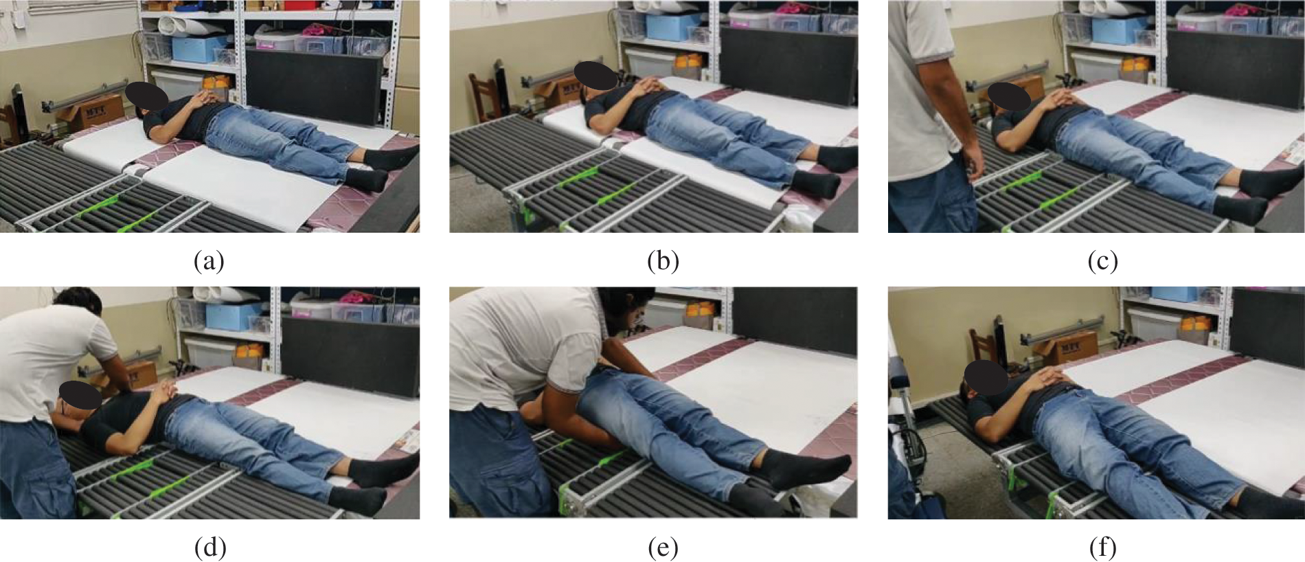
Figure 10: Snapshots when transferring the user from the bed to the wheelchair
3.2 Case 2: Subject Performing Toileting Process
In daily routine, the disabled and older persons must go to the toilet, but for a person who is confined to a wheelchair, this task can be challenging. In this section, the performance of the body-transfer wheelchair during the toileting process was examined. The toilet commode is 45.6 cm high and 20 cm wide as shown in Fig. 11. Fig. 11 shows the user is seated directly above the toilet. Before the wheelchair approaches the toilet, as shown in Fig. 11a, users can adjust the level of the wheelchair to the level of the toilet commode. Then, the user can move the wheelchair backward and maintain the direction and position relative to the toilet to avoid a crash, as shown in Figs. 11d and 11c. It is verified that the subject could reach the desired position above the toilet commode and successfully use the prototype for toileting. User can open the toilet slot by pulling the toilet handle, furthermore, the need to transfer to another system for performing the toileting task has been avoided which reduce the risk of injury which is the main advantage of opting for such kind of toileting mechanism. Once toileting has been completed the user can close the toilet slot by pushing back the toilet handle to its original handle. For toileting, the transfer process is quite fast, less than 1 min starting from the wheelchair coming to the toilet until reaching the commode.
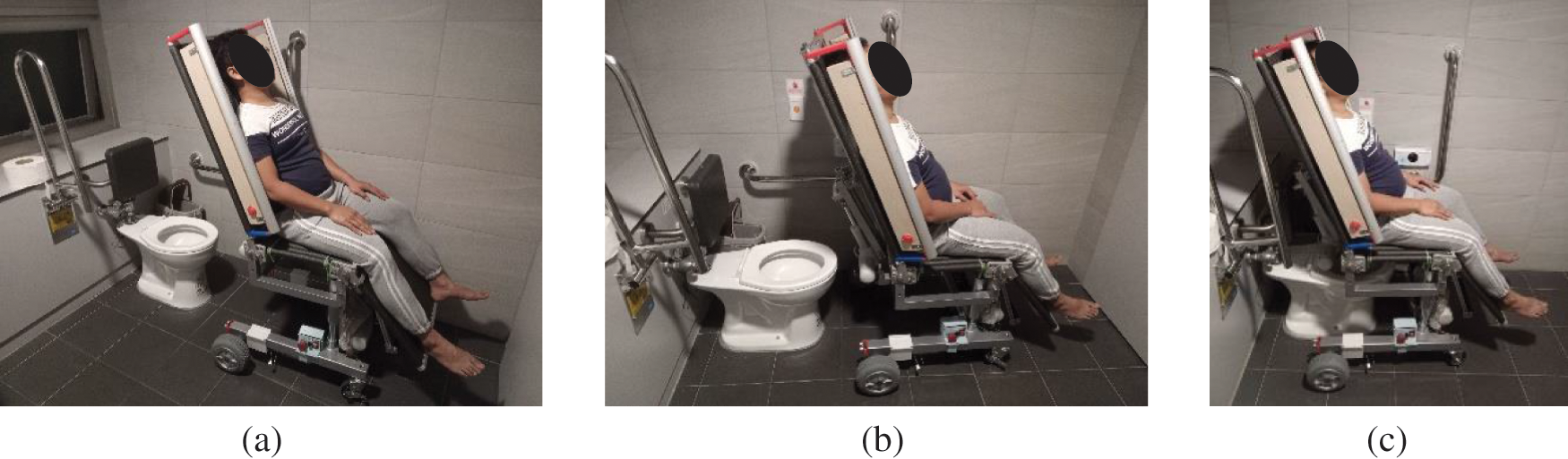
Figure 11: Snapshots when transferring to a toilet
3.3 Case 3: Subject Transferred from Body-Transfer Wheelchair to Bathtub
To alleviate the possibility of an accident, an extension rail mechanism has been proposed to transfer a person from a wheelchair to a bathtub. Fig. 12 shows the transfer of the user from the wheelchair to the bathtub. The rail and aluminum frame represents the bathtub construction and is simplified by using four-leg aluminum frames to support the rail. The transfer process starts with the positioning of the wheelchair by the caregiver with the bathtub. After proper positioning, the caregiver needs to extend the rail mounted on the bathtub and attach it to the detachable seat. Once the seat frame (carrying object) is firmly connected to the rail, the caregiver can separate the seat frame from the base frame. As shown in Figs. 12c and 12d, the caregiver can smoothly slide the frame into the bathtub. This mechanism reduces the significant amount of the burden from the caregiver and dangers of risk and injuries to the user can be avoided. A reverse process can be followed to remove the user from the bathtub and transfer them back to the wheelchair frame. Since the seat frame is composed of a roller so it is also convenient for the caregiver to dry the users effortlessly. We conducted various experiments to verify the barrier-free transfer of people from the wheelchair to the bathtub. Generally, there is variation in the bathtub sizes. In such a case, height adjustment is required to maintain the plane between the wheelchair and the rail position. The interlocking mechanism installed on the seat is engaged, and the sitting posture is maintained. This mechanism also assures a balance between the backrest and leg rest during the transfer process. In the bathtub, the transfer process needs less than 2 min to start from adjusting the wheelchair height until the person reaches the bathtub rail.
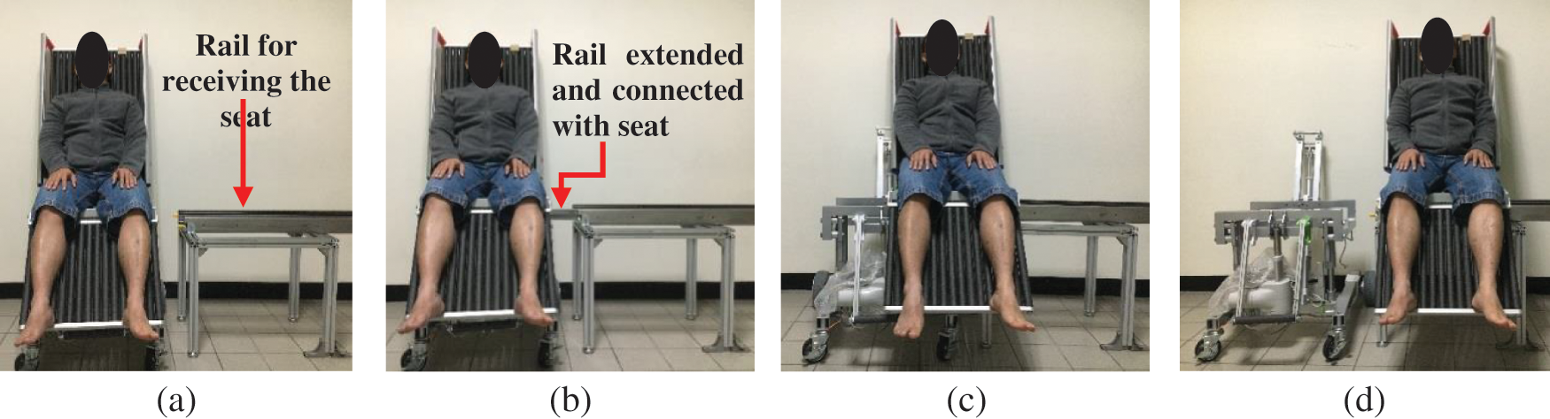
Figure 12: Snapshots when transferring to a bathtub
4 User Evaluation of Body-Transfer Wheelchair
For assessing the performance and acceptability of body-transfer wheelchair in terms of ease of transfer, safety, comfort, stability, aesthetics, and reduction of the burden on the caregivers and functionally impaired people, while transfer, two focus groups were selected. These focus groups include wheelchair users and professional caregivers. 15 wheelchair users, who have been using the wheelchair for at least 5 years, out of which 10 were men and 5 women. 12 participants were using the manual wheelchair and 3 were using an electric-powered wheelchair. Similarly, in a separate focus group, five professional caregivers with at least one year of transfer experience took part.
A short survey was given to the participants after they had given their informed consent. This survey included basic demographic data such as age, gender, and race, as well as information regarding the type of disability, years of transfer experience, and assistive systems used. An in-depth presentation on the features and operations of the body-transfer wheelchair was given to both focus groups. Following the presentation, another survey was conducted by them. The purpose of this survey was to find out what people thought of the body-transfer wheelchair in general. The data were analyzed using 7-point Likert scales. When asked to rank the importance of a question, 1 to 2 was judged insignificant, 3 to 5 was neutral, and 6 to 7 was significant. For questions that asked for a level of agreement with a statement, the same procedure was used: 1 to 2 meant disagree, 3 to 5 meant neutral, and 6 to 7 meant to agree.
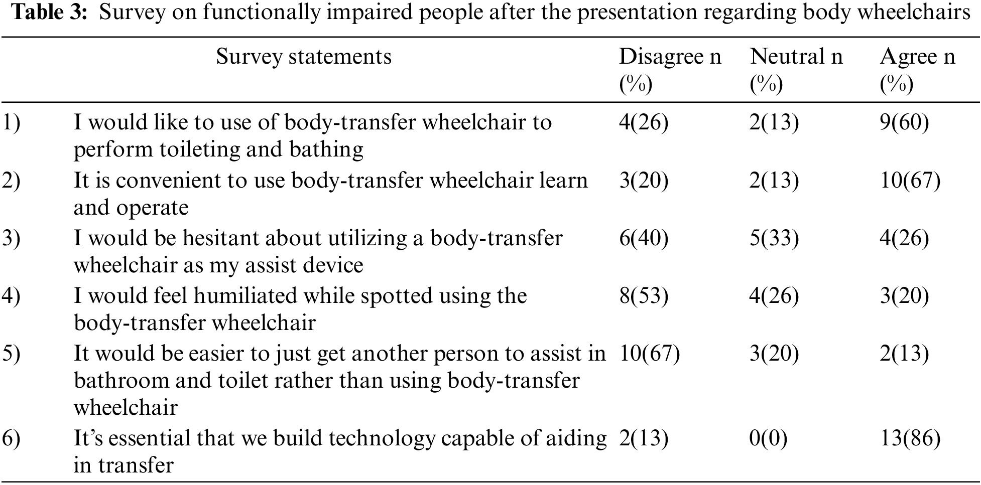
Table 3 shows the results of the post-presentation survey on the body-transfer wheelchair overall thoughts. 60% of participants with functional impairments indicated their willingness to use the body-transfer wheelchair. However, 26% of those polled stated they would not use the proposed system, and only 13% remained neutral. Similarly, 67% of the people agreed that it is very convenient and beneficial in their daily life. The development of this wheelchair was deemed significant by all participants, and 86% agreed that the resources should be devoted by the governmental and private sector to further develop the Body-transfer wheelchair. The most significant qualities of the equipment, according to participants, were ease of transfer, safety, and stability, while aesthetics was rated as the least important parameter.
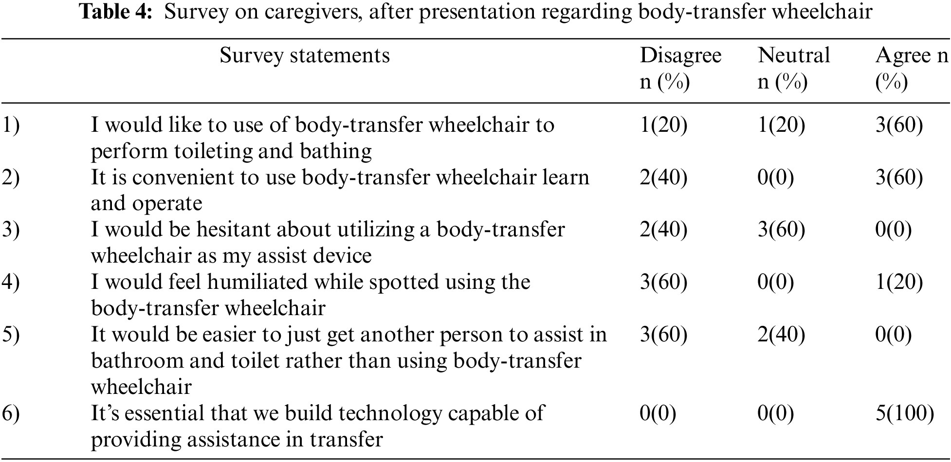
Three men and two women made up the caregiver focus group. The average age of the participants was 35 years. One caregiver assisted a person who used both a manual and a power wheelchair whereas, the rest of them helped their clients using a manual wheelchair. Two caregivers used hydraulic lifts and three of them used powered lifts. 40% of caregivers had less than five years of experience performing transfers. During a transfer, two caregivers stated that they were hurt. Only one caregiver prefers not to use the body-transfer wheelchair for toileting and bathing, however, the rest of them would rather opt for the prototype. Regarding the aesthetic aspect majority of the caregivers remained neutral. All the participants agreed that this kind of assisted system should be developed, as shown in Table 4.
Technology that enables secure and efficient transfers inside the home is in more demand, as the population ages and their desire to stay at home is increasing. Majority of the previously developed solutions help the user to transfer from a bed or toilet to a wheelchair by lifting. Also during the transfers, end-users and caregivers felt a lot of pressure on their upper limbs which resulting shoulder, elbow, and hand discomfort [37,38]. In [39], it has been demonstrated that the most difficult tasks in performing ADLs is toileting and bathing. Additionally, repositioning a person in bed or in a wheelchair, which occurs at the end of the transfer process, is quite physically hectic and frequently results in musculoskeletal pain and injury [40]. Furthermore, due to the costs and space restrictions associated with adopting assistive technology in home settings, manual assistance is generally provided to disabled individuals which leads to discomfort and put enormous physical strain on the caregivers [41]. Also, these devices are unable to maintain the human body’s sagittal plane at a consistent angle. Compared to the previous systems, body-transfer wheelchairs have the following strengths:
• Due to the sliding transfer strategy, the transfer of a person is convenient, and the physical strain felt by the caregiver has been reduced.
• The individual can perform toileting using the linkage toilet mechanism mounted on the seat.
• The user can bathe with the help of a detachable seat mechanism. Subsequently, both toileting and bathing can be carried out while sitting in the same chair without the need for a separate transfer device. Thus the risk of falling while transfers have been mitigated.
• The issue of maintaining the human body’s sagittal plane at a consistent angle, human when patients are transferred from bed to wheelchair is addressed by replacing the traditional seat with soft foam rollers. So the person can be transferred and repositioned effortlessly.
The post-presentation survey results from the attendees were encouraging. Most of the disabled individuals and caregivers either expressed their agreement to utilize the body-transfer wheelchair or remained neutral. Since they perceive a reduction in physical load while using this system. Both groups have noted that the body-transfer wheelchair can be used independently in toilets and bathrooms, which preserves the integrity of individuals. Size and independent operation are the two most significant concerns for both groups.
One of the caregivers declined to use a body-transfer wheelchair because it is difficult to remove the clothes of their clients while using this system. Moreover, most caregivers oppose the concept of manual transfer of the user of the wheelchair to the bathtub using the guide rail, instead, they would wish to have a fully powered transfer system for the bathtub. Therefore, a body-transfer wheelchair could reduce the frequency of musculoskeletal injuries and physical stress experienced by caregivers [42,43]. Moreover, if a person who needs assistance in performing ADLs, losses that person due to any reason then institutional care is frequently recommended.
Earlier research focused on the lifting transfer system to help users in toileting and bathing, which was uncomfortable and risky. We propose a body-transfer wheelchair for transferring users from bed to a wheelchair for toileting and bathing. The proposed system solves these problems and outperforms previous methods. The proposed system improves user safety and comfort. It also reduces the caregiver’s burden when transferring and assisting the functionally impaired in the toilet and bathroom. Summary of the proposed approach:
• The body-transfer wheelchair has been designed and developed to carry a load of 150 kg. It is a semi-automatic, multi-functional wheelchair that has features such as a controlled leg and backrest, linkage commode slot, and height adjustment mechanism. The overall dimensions of a body-transfer wheelchair confirm that it can be maneuvered in-home settings.
• The wheelchair comprises two components a U-shaped mainframe and a detachable seat. The U-shaped mainframe and height adjustment mechanism enables the wheelchair to assist the user in transferring to bed and performing toileting on commode of various heights.
• Using a detachable seat in combination with an extension rail mechanism, the bathtub’s transfer process can be performed smoothly and safely. Batteries and a control system are placed on the mainframe underneath the seat. Furthermore, during bathing, the users’ seat is completely disengaged from the mainframe, ensuring the system is electrically safe during its operation.
• A linkage slot mechanism is mounted on the seat which allows the user to do toileting without being transferred to another system, subsequently, the chance of injuries and risk of falling is reduced.
• Focus group results were 67% of functionally impaired people and 60% of caregivers recommend using the body-transfer wheelchair as compared to commercially available transfer systems. However, more study is needed before this wheelchair can be used by individuals who could benefit from it.
This study had some limitations, including small sample size and a prototype being tested in a controlled environment. Consequently, the survey results of these focus groups are not a full representation of the actual target population.
Future work on the body-transfer wheelchair will be to make a fully powered transfer system, testing in the home and hospital setting during which the caregivers can transfer the users. The developed prototype needs some structural changes like placing the guide rail on the bathtub so in the next step it can be part of the wheelchair so the requirement of structural changes can be eliminated.
Funding Statement: This work is financially supported by both Taiwan Building Technology Center and Center for Cyber-physical System Innovation from the Featured Areas Research Center Program within the framework of the Higher Education Sprout Project by the Ministry of Education (MOE) in Taiwan. This research is also financially supported by the Ministry of Science and Technology, Republic of China, Under Grant 108-2221-E-011-140-MY2.
Conflicts of Interest: The authors declare that they have no conflicts of interest to report regarding the present study.
References
1. E. Rudnicka, P. Napierała, A. Podfigurna, B. Męczekalski, R. Smolarczyk et al., “The world health organization (WHO) approach to healthy ageing,” Maturitas, vol. 139, pp. 6–11, 2020. [Google Scholar]
2. A. C. Lyons, J. E. Grable and S. -H. Joo, “A Cross-country analysis of population aging and financial security,” The Journal of the Economics of Ageing, vol. 12, pp. 96–117, 2018. [Google Scholar]
3. K. Eggleston, J. C. Oi, S. Rozelle, A. N. G. Sun, A. Walder et al., “Will demographic change slow China’s rise?” The Journal of Asian Studies, vol. 72, no. 3, pp. 505–518, 2013. [Google Scholar]
4. S. Katz, A. B. Ford, R. W. Moskowitz, B. A. Jackson and M. W. Jaffe, “Studies of illness in the aged: The index of ADL: A standardized measure of biological and psychosocial function,” JaMa, vol. 185, no. 12, pp. 914–919, 1963. [Google Scholar]
5. F. Grimsland, A. Seim, T. Borza and A. S. Helvik, “Toileting difficulties in older people with and without dementia receiving formal in-home care-A longitudinal study,” Nursing Open, vol. 6, no. 3, pp. 1055–1066, 2019. [Google Scholar]
6. R. Hacihasanoğlu, A. Yildirim and P. Karakurt, “Loneliness in elderly individuals, level of dependence in activities of daily living (ADL) and influential factors,” Archives of Gerontology and Geriatrics, vol. 54, no. 1, pp. 61–66, 2012. [Google Scholar]
7. H. R. Bogner, “Urinary incontinence and psychological distress in community-dwelling older African Americans and Whites,” Journal of the American Geriatrics Society, vol. 52, no. 11, pp. 1870–1874, 2004. [Google Scholar]
8. J. Avery and N. Stocks, “Urinary incontinence, depression and psychological factors-A review of population studies,” European Medical Journal Urology, vol. 1, pp. 58–67, 2016. [Google Scholar]
9. D. D. Dunlop, S. L. Hughes and L. M. Manheim, “Disability in activities of daily living: Patterns of change and a hierarchy of disability,” American Journal of Public Health, vol. 87, no. 3, pp. 378–383, 1997. [Google Scholar]
10. D. Gu and Q. Xu, “Sociodemographic effects on the dynamics of task-specific ADL functioning at the oldest-old ages: The case of China,” Journal of Cross-Cultural Gerontology, vol. 22, no. 1, pp. 61–81, 2007. [Google Scholar]
11. N. Robert, “How artificial intelligence is changing nursing,” Nursing Management, vol. 50, no. 9, pp. 30–39, 2019. [Google Scholar]
12. S. Sivakanthan, E. Blaauw, M. Greenhalgh, A. M. Koontz, R. Vegter et al., “Person transfer assist systems: A literature review,” Disability and Rehabilitation: Assistive Technology, vol. 16, no. 3, pp. 270–279, 2021. [Google Scholar]
13. A. Rush, “Assessing clients for the correct hoist or sling: A practical guide,” International Journal of Therapy and Rehabilitation, vol. 11, no. 4, pp. 179–182, 2004. [Google Scholar]
14. H. Jeannis, G. G. Grindle, A. Kelleher, H. Wang, B. Brewer et al., “Initial development of direct interaction for a transfer robotic arm system for caregivers,” in Proc. of the IEEE 13th Int. Conf. on Rehabilitation Robotics (ICORR), Seattle, Washington, USA, pp. 1–5, 2013. [Google Scholar]
15. H. Wang, C. Y. Tsai, H. Jeannis, C. S. Chung, A. Kelleher et al., “Stability analysis of electrical powered wheelchair-mounted robotic-assisted transfer device,” Journal of Rehabilitation Research and Development, vol. 51, no. 5, pp. 761–774, 2014. [Google Scholar]
16. J. Burkman, G. Grindle, H. Wang, A. Kelleher and R. A. Cooper, “Further development of a robotic-assisted transfer device,” Topics in Spinal Cord Injury Rehabilitation, vol. 23, no. 2, pp. 140–146, 2017. [Google Scholar]
17. R. Bostelman, J. Albus and T. Chang, “Recent developments of the HLPR chair,” in Proc. of the 2007 IEEE 10th Int. Conf. on Rehabilitation Robotics, Noordwijk, Netherlands, pp. 1036–1041, 2007. [Google Scholar]
18. Y. Mori, N. Sakai and K. Katsumura, “Development of a wheelchair with a lifting function,” Advances in Mechanical Engineering, vol. 4, pp. 1–9, 2015. [Google Scholar]
19. T. Yukawa, Y. Kuramochi, T. Takahashi and K. Takahashi, “Nursing-care system for bedridden patients with electric wheelchair, lift, portable bath, mobile robot and portable toilet,” International Journal of Engineering and Innovative Technology (IJEIT), vol. 2, no. 5, pp. 100–108, 2012. [Google Scholar]
20. A. Sivaprakasam, H. Wang, R. A. Cooper and A. M. Koontz, “Innovation in transfer assist technologies for persons with severe disabilities and their caregivers,” IEEE Potentials, vol. 36, no. 1, pp. 34–41, 2017. [Google Scholar]
21. R. H. Krishnan and S. Pugazhenthi, “Mobility assistive devices and self-transfer robotic systems for elderly, a review,” Intelligent Service Robotics, vol. 7, no. 1, pp. 37–49, 2014. [Google Scholar]
22. A. Garg and J. M. Kapellusch, “Long-term efficacy of an ergonomics program that includes patient-handling devices on reducing musculoskeletal injuries to nursing personnel,” Human Factors, vol. 54, no. 4, pp. 608–625, 2012. [Google Scholar]
23. M. K. Daily, “Evaluation of a continued safe patient and handling program,” Doctor of Nursing Practice (DNP) Projects, University of Massachusetts Amherst, United States, pp. 434–456, 2014. [Google Scholar]
24. Y. Tian, H. Wang, Y. Zhang, B. Su, L. Wang et al., “Design and evaluation of a novel person transfer assist system,” IEEE Access, vol. 9, pp. 14306–14318, 2021. [Google Scholar]
25. T. Jacobs and G. S. Virk, “ISO 13482-The new safety standard for personal care robots,” in Proc. of the ISR/Robotik 2014; 41st Int. Symp. on Robotics, Munich, Germany, pp. 1–6, 2014. [Google Scholar]
26. W. Karwowski, “Ergonomics and human factors: The paradigms for science, engineering, design, technology and management of human-compatible systems,” Ergonomics, vol. 48, no. 5, pp. 436–463, 2005. [Google Scholar]
27. X. Shi, H. Lu and Z. Chen, “Design and analysis of an intelligent toilet wheelchair based on planar 2DOF parallel mechanism with coupling branch chains,” Sensors (Basel), vol. 21, no. 8, pp. 45–69, 2021. [Google Scholar]
28. P. Wenhan, “Investigation on the changes of national nutrition and health status,” National Health Administration of the Ministry of Health and Welfare,Taiwan, pp. 66–87, 2016. [Google Scholar]
29. R. C. Hibbeler, “Planar kinematics of a rigid body,” in Engineering Mechanics Statics & Dynamics, 14th ed., Hoboken, New Jersey, USA: Pearson Prentice Hall, pp. 760–780, 2015. [Google Scholar]
30. D. V. Rosato and D. V. Rosato, “Safety factor,” in Plastics Engineered Product Design, 1st ed., United Kindom (UKElsevier Advanced Technology, pp. 569–587, 2003. [Google Scholar]
31. H. J. M. Al-Alkawi, S. T. Faris and S. N. Naji, “Combine shot penning (SP) and ultrasonic impact treatment (UIT) for soil corrosion buckling strength enhancement of AA 2014-t4,” Al-Nahrain Journal for Engineering Sciences, vol. 23, no. 2, pp. 144–152, 2020. [Google Scholar]
32. J. A. Collins, H. R. Busby and G. H. Staab, “Materials selection,” in Mechanical Design of Machine Elements and Machines: A Failure Prevention Perspective, 2nd ed., United States of America (USAJohn Wiley & Sons, pp. 858–868, 2009. [Google Scholar]
33. J. Rui and Q. Gao, “Design and analysis of a multifunctional wheelchair,” in Proc. of the IOP Conf. Series: Materials Science and Engineering, Chengdu, China, pp. 012045–012063, 2019. [Google Scholar]
34. K. Waugh and B. Crane, “Angular support surface measures,” in A Clinical Application Guide to Standardized Wheelchair Seating Measures of the Body and Seating Support Surfaces, 1st ed., Denver, Colorado, USA: University of Colorado & Assistive Technology Partners, pp. 65–85, 2013. [Google Scholar]
35. A. Nayyar, “An encyclopedia coverage of compiler’s, programmer’s & simulator’s for 8051, PIC, AVR, ARM, Arduino embedded technologies,” International Journal of Reconfigurable and Embedded Systems, vol. 5, no. 1, pp. 654–678, 2016. [Google Scholar]
36. A. Nayyar and V. Puri, “A review of Arduino board’s, Lilypad’s & Arduino shields,” in Proc. of the 2016 3rd Int. Conf. on Computing for Sustainable Global Development (INDIACom), New Delhi, India, pp. 1485–1492, 2016. [Google Scholar]
37. K. Samuelsson, H. Tropp and B. Gerdle, “Shoulder pain and its consequences in paraplegic spinal cord-injured, wheelchair users,” Spinal Cord, vol. 42, no. 1, pp. 41–46, 2004. [Google Scholar]
38. C. Thunborg, P. von Heideken Wågert, A. Söderlund and E. Götell, “Reciprocal struggling in person transfer tasks–caregivers’ experiences in dementia care,” Advances in Physiotherapy, vol. 14, no. 4, pp. 175–182, 2012. [Google Scholar]
39. T. Janssen, C. Van Oers, H. Veeger, A. Hollander, L. Van der Woude et al., “Relationship between physical strain during standardised ADL tasks and physical capacity in men with spinal cord injuries,” Spinal Cord, vol. 32, no. 12, pp. 844–859, 1994. [Google Scholar]
40. C. Weiner, D. Alperovitch-Najenson, J. Ribak and L. Kalichman, “Prevention of nurses’ work-related musculoskeletal disorders resulting from repositioning patients in bed: Comprehensive narrative review,” Workplace Health & Safety, vol. 63, no. 5, pp. 226–232, 2015. [Google Scholar]
41. J. A. Hess, L. D. Kincl and D. S. Mandeville, “Comparison of three single-person manual patient techniques for bed-to-wheelchair transfers,” Home Healthcare Now, vol. 25, no. 9, pp. 577–579, 2007. [Google Scholar]
42. A. R. Darragh, C. M. Sommerich, S. A. Lavender, K. J. Tanner, K. Vogel et al., “Musculoskeletal discomfort, physical demand, and caregiving activities in informal caregivers,” Journal of Applied Gerontology, vol. 34, no. 6, pp. 734–760, 2015. [Google Scholar]
43. L. A. Pompeii, H. J. Lipscomb, A. L. Schoenfisch and J. M. Dement, “Musculoskeletal injuries resulting from patient handling tasks among hospital workers,” American Journal of Industrial Medicine, vol. 52, no. 7, pp. 571–578, 2009. [Google Scholar]
Cite This Article
 Copyright © 2023 The Author(s). Published by Tech Science Press.
This work is licensed under a Creative Commons Attribution 4.0 International License , which permits unrestricted use, distribution, and reproduction in any medium, provided the original work is properly cited.
 Downloads
 Citation Tools