
 Submit a Paper
 Propose a Special lssue
 Open Access
ARTICLE

MCRO-PUF: A Novel Modified Crossover RO-PUF with an Ultra-Expanded CRP Space
1 Department of Electrical Engineering, Iran University of Science and Technology, Tehran, 13114-16846, Iran
2 Department of Communication and Networking, Aalto University, Espoo, 00076, Finland
3 ETSI de Telecomunicación, Universidad Politécnica de Madrid, Av. Complutense 30, Madrid, 28040, Spain
* Corresponding Author: Diego Martín. Email:
Computers, Materials & Continua 2023, 74(3), 4831-4845. https://doi.org/10.32604/cmc.2023.034981
Received 02 August 2022; Accepted 20 October 2022; Issue published 28 December 2022
 View Full Text
 Download PDF
Abstract
With the expanding use of the Internet of Things (IoT) devices and the connection of humans and devices to the Internet, the need to provide security in this field is constantly growing. The conventional cryptographic solutions need the IoT device to store secret keys in its non-volatile memory (NVM) leading the system to be vulnerable to physical attacks. In addition, they are not appropriate for IoT applications due to their complex calculations. Thus, physically unclonable functions (PUFs) have been introduced to simultaneously address these issues. PUFs are lightweight and easy-to-access hardware security primitives which employ the unique characteristics of integrated circuits (ICs) to generate secret keys. Among all proposed PUFs, ring oscillator PUF (RO-PUF) has had a more suitable structure for hardware implementation because of its high reliability and easier providing of circuital symmetry. However, RO-PUF has not been so attractive for authentication purposes due to its limited supported challenge-response pairs (CRPs). A few efforts have been made in recent years that could successfully improve the RO-PUF CRP space, such as configurable RO-PUF (CRO-PUF). In this paper, by considerably improving the CRO-PUF structure and adding spare paths, we propose a novel strong RO-PUF structure that exponentially grows the CRP space and dramatically reduces the hardware cost. We implement our design on a simple and low-cost FPGA chip named XC6SLX9-2tqg144, stating that the proposed design can be used in IoT applications. In addition, to improve the CRP space, our design creates a suitable improvement in different security/performance terms of the generated responses, and dramatically outperforms the state-of-the-art. The average reliability, uniqueness, and uniformity of the responses generated are 99.55%, 48.49%, and 50.99%, respectively.Keywords
The Internet of Things (IoT) describes a world in which everything, including inanimate objects, has a digital identity of its own and allows computers to organize and manage them. In recent years, engineers/researchers have comprehended that our physical world is an information system in itself. Much information can be collected and used from sensors and actuators. Despite the growing demand for IoT, security challenges are a significant worry in developing this technology. IoT security problems that seem to be irrecoverable are challenging for two reasons. On the one hand, the IoT requires the highest level of security. IoT technology enables a wide range of applications in various environments, such as industrial activities, smart cities, and healthcare systems. In the event of a security breach in the IoT system, attackers could access personal information, trade secrets, and military documents. On the other hand, increasing the level of security is always accompanied by (different kinds of) costs [1].
Many IoT devices have limited resources to meet high-security requirements due to size, weight, and portability. Employing a conventional security approach in IoT leads to low efficiency and high maintenance costs. For this reason, a practical method is needed to make the highest level of security possible with the least energy and computing power. In most cases, security issues at the software level cause attackers to abuse especially physical attacks. Therefore, hardware-oriented security solutions have attracted much attention in recent years. These alternatives give the designers an exceptional opportunity to minimize energy and cost and provide solutions to problems that cannot be solved with traditional cryptography [2].
It is reported that even the U.S. Department of Defense has been deceived into buying more than one million counterfeit electronic devices [3], which shows the high importance of device authentication. Physical unclonable functions (PUFs) have been introduced as promising tools to solve both security and overhead problems in IoT [4]. PUFs offer a promising approach to secure cyber-physical systems and solve issues of traditional solutions. PUFs use the physical structure of each chip to generate a unique identity. Even if several chips have the same manufacturing process, small random changes and differences during the IC manufacturing process will produce unique and unclonable fingerprints. This unique fingerprint can be used to authenticate devices and generate cryptographic keys [5,6].
However, hardware security solutions also face challenges. In [7], cyber-attacks against hardware platforms are examined in three groups: Invasive, non-invasive, and semi-invasive attacks. As mentioned, traditional cryptographic approaches are ineffective in preventing attacks such as counterfeiting, cloning, and reverse engineering. This issue is because the traditional approaches store the secret key in non-volatile memories (NVMs), such as electrically erasable programmable read-only memory (EEPROM). Attackers can directly access the data stored on this type of memory. Even if expensive coatings are used for the devices, they will still be vulnerable to complex physical attacks. PUF, as an innovative challenge-response-based black box, is used in physical systems to provide the required security goals. Instead of storing secret keys in NVM, PUF inherently generates unpredictable keys during the protocol execution [8–10].
A PUF implements a one-way function on an electronic device; even if an attacker has access to the circuit and exactly uses the same components to build the same circuit, for a particular challenge, the response of the new device and the main device will be different [5–7]. Silicon PUFs are divided into two categories: memory-based PUFs and delay-based PUFs. Silicon PUFs are based on behaviors embedded in silicon chips, such as internal delay and hidden timing. The basic idea of memory-based PUFs is to get a bistable memory to the metastable state so that it is unclear which steady state has retreated. For different components of memory, this solution is completely random and unpredictable because the physical changes are random. However, these PUFs support a very limited set of challenge-response pairs (CRPs), which makes them inappropriate for authentication purposes.
In delay-based PUFs, gate delay generates response bits [5–11]. The most well-known delay-based PUFs are arbiter PUF (APUF), ring-oscillator PUF (RO-PUF), and glitch PUF, among which RO-PUF has a more suitable structure for hardware implementation because of its high reliability and easier providing of circuital symmetry. Fig. 1 shows a basic RO-PUF. Since the original RO-PUF supports a small set of CRPs, it has been classified as a weak PUF. The frequency of each RO depends on the delay of the gates and wires, which is impossible to predict due to the IC production process variation.
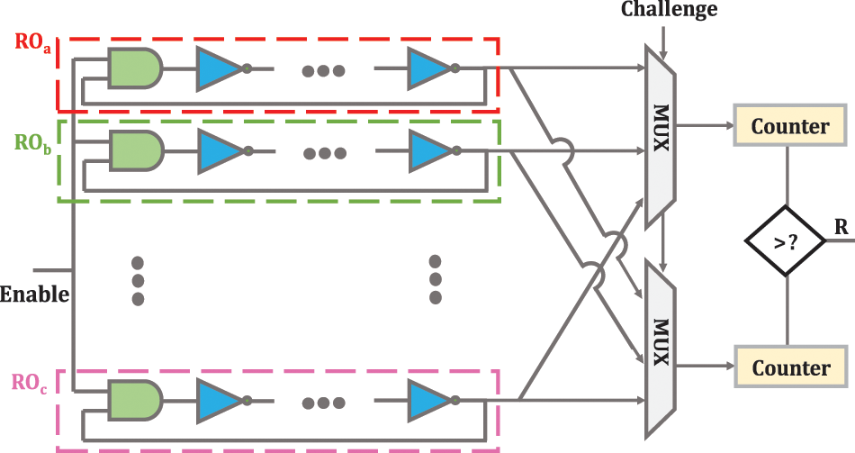
Figure 1: RO-PUF structure [13,14]
A basic RO-PUF consists of two ROs, two counters, and a comparator. ROs have a simple circuit and consist of several inverters connected inside a loop. When the enable signal is activated, the number of logic cycles of each RO is counted by the respective counter. Finally, the comparator compares the enumerated values and produces one digit based on the difference between the counters’ values. Obviously, the number of CRPs that RO-PUF can generate is directly related to the number of ROs used in the PUF structure [12]. RO-PUF makes the delays difference measurable by magnifying the delay difference between ROs. Like other silicone PUFs, RO PUFs are very impressionable to environmental factors, so it will be very difficult for RO PUFs to produce completely stable responses. Furthermore, the lack of large CRP space has limited the use of RO PUF for authentication and key generation purposes [13,14].
Among intrinsic PUFs, APUF is the first silicon PUF to use an arbiter block to compare the delay of two specific paths. However, it is not easy to create symmetrical paths to ensure high uniqueness features, especially for FPGA implementation. To eliminate the problem of symmetric routing, RO-PUF is proposed as an FPGA-compliant scheme that compares the frequency cycle period rather than the path delay. However, RO-PUF produces fewer response bits at an equal area than APUF. More response bits (i.e., CRP) mean an increase in working life in terms of the number of authentication times. This means that RO-PUF requires far more area to collect equal CRP than APUF. Although several structures of PUFs have been introduced to do on that score, they all face two main problems: unreliability and predictability. Unreliability means that all device parameters are more or less sensitive to environmental factors. If environmental factors (temperature and voltage source) change significantly, it is difficult to guarantee that CRPs will be stable. Error correction code (ECC) techniques and fault-tolerant techniques are widely used to improve reliability. Predictability basically means the correlation between CRPs that is achieved with a specific hardware structure or unmeasured dependency. For example, the APUF path delay is exactly the same as the fault-tolerant model. So, they are easily attacked by machine learning methods. Of all the inherent silicon PUFs, RO-PUF is expected to be a good choice that can provide a suitable trade-off between different criteria [1].
To solve the stability problem of RO PUF, the authors in [15] and [16] proposed a way to increase the frequency difference of ROs, so that the PUF response will be reliable with temperature variations since the relationship between temperature and frequency is almost linear. However, the main problem with RO PUF is still the lack of enough CRP space. In [12], a method has been proposed to increase the CRP space of RO-PUF. In this method, first, an arbitrary subset of the set of ROs is randomly selected, then comparing each element of the selected subset with other ROs is performed. If the total number of ROs is n, the total number of selected subsets is 2n−1. Therefore, the number of CRPs can be increased to 2n−1. The number of response bits of this PUF per each challenge has been increased to n−1. In fact, the first RO increases the set of CRPs and the second RO increases the number of response bits corresponding to each challenge. After comparing the frequency of each RO with other ROs, an n−1-bit vector called the comparison vector is generated. By applying XOR to the comparison vector and a random vector, the final response with a uniqueness of 49.81% and reliability of 96.07% is obtained.
In previous RO-PUFs, the number of ROs was increased to improve reliability; however, exorbitant hardware costs were imposed. In addition, previous RO-PUFs exhibited a static challenge-response behavior. The concept of configurability for RO-PUFs was first introduced in [17], where a multiplexer RO in each stage selects one of the two input paths, and every eight configurations belong to a three-story RO.
Fig. 2a shows the structure of a configurable RO. If the input of the multiplexer selection of each stage is “1”, the inverter corresponding to that multiplexer is added to RO; otherwise, the inverter of that stage is left unused. Thus, in this scheme, there is a condition for selecting the input bits, and it is impossible to apply the whole input mode because the length of the two selected ROs may not be equal. Configurable PUF exhibited a dynamic, unpredictable challenge-response behavior [18].
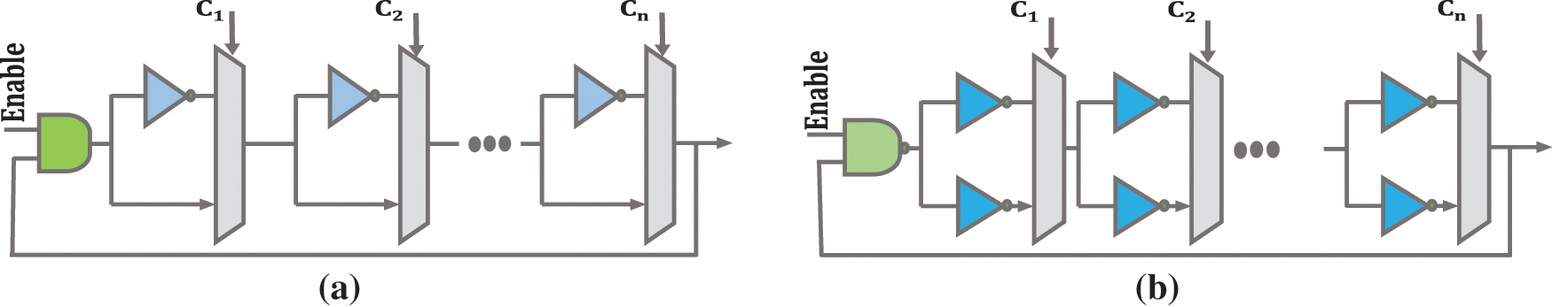
Figure 2: (a) Proposed configurable RO in [18]; (b) Proposed configurable RO in [19]
An improved structure for the structure of Fig. 2a is presented in [19]. In this structure, the problem of idle inverters has been solved. A configurable RO can generate very stable responses in various conditions because it can dynamically adjust itself and select the most stable RO pair depending on the conditions. A simple RO can only have a static configuration and does not have the ability to increase the reliability of the bit response [19]. Fig. 2b shows the proposed structure in [19]. For a normal RO, if the frequency ROa is greater than ROb and the frequency ROb is greater than ROc, then the frequency ROa is definitely higher than ROc. Therefore, a typical RO-PUF can be attacked and consume many hardware resources. This feature makes the reconfigurable PUFs to be efficiently resisted against modeling and man-in-the-middle (MITM) attacks.
The authors in [20] introduced crossover RO-PUF (CRO-PUF) to improve its reliability and resistance to possible attacks such as FPGA replay attacks, modeling attacks, and MITM attacks, which has advantages in flexibility and reliability terms over the configurable RO-PUFs. An important point that should be paid attention to is that the delay of the interstage crossing may affect the overall delay of the PUF, which can be minimized with the available design tools [21]. For example, inverters of an RO can be connected together with paths of different lengths and bias the PUF circuit [20]. This structure can physically generate the same lightweight shared key for devices with limited resources. All nodes must have the same encryption/decryption keys in multi-party communication. With this structure, generating the same key for several nodes is easy, though stable responses will be needed. A threshold value is used to ensure the stability of CRO-PUF responses so that the generated responses are reliable in different environmental conditions.
Furthermore, this design saves on hardware consumption, and it will be difficult for attackers to predict the keys [21]. The structure of CRO-PUF is shown in Fig. 3. The CRO-PUF uses several interstage crossing stages that have one-to-one input-output mapping. Changing the interstage crossing configuration leads to changing the signal path without adding the logical operation to change the overall delay of each RO. In this case, with a certain number of inverters, much more ROs can be generated than conventional RO-PUFs. A LUT with n inputs can be used to construct the interstage crossover. In this structure, m is odd and greater than two. In this structure, the number of CRPs increases exponentially concerning n and m by generating (n!)m−2 different configurations. In this structure, there is n RO where each RO has m inverters. As m increases, the number of inverters of an RO increases, and its frequency RO decreases.
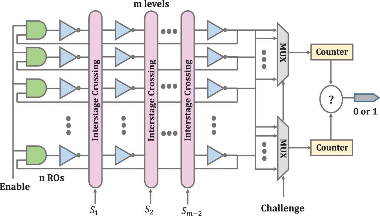
Figure 3: CRO-PUF structure [20]
The only limitation for configuration in this design is a one-to-one mapping, and designers can follow this limitation to do the configuration and internal connections as arbitrary. After configuring the interstage crossing blocks, a set of ROs is obtained. The two ROs are selected by the input challenge applied to the multiplexer. After counting and calculating, the final output frequency is determined in the comparator. This method can configure all connections without the effect of routing on the redirection matrices. This means that it can improve the reliability of RO-PUF [20,21].
An example of the CRO-PUF routing is shown in Fig. 4, which shows the high flexibility of this structure. With this structure, when the frequency difference between the two ROs is very small, this frequency difference can be increased to an acceptable numerical value so that the circuit’s response does not change by changing the environmental conditions. In terms of security analysis, since the interstage crossing and the inverter are independent of each other, attackers cannot obtain the delay information of the inverters by obtaining the configuration of the interstage crossing cells. Even if they can get all the configuration bits of the interstage crossing cells, they still do not know which inverters will be selected in RO because they have no information about the selected bit.
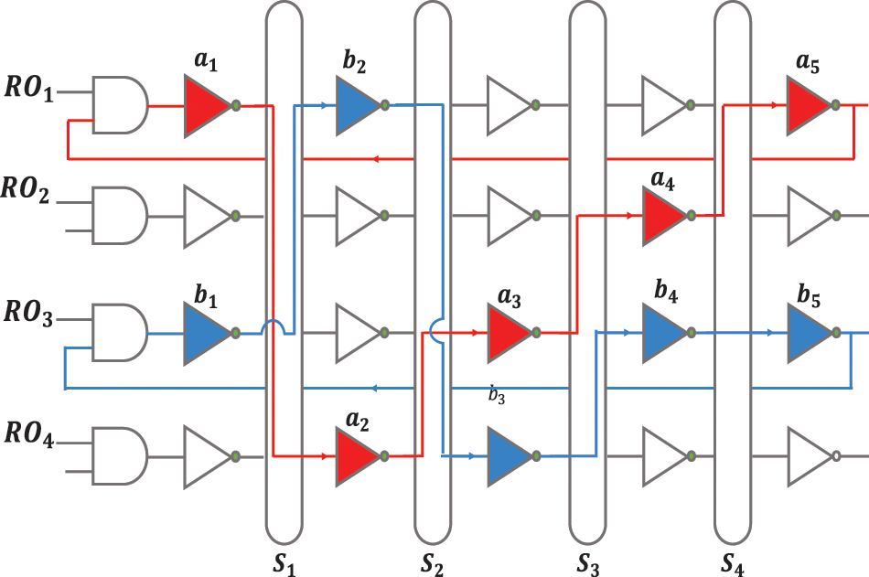
Figure 4: An example of two delay paths for CRO-PUF [21]
In this structure, the inverters of each RO can be dynamically changed with different configurations to produce an unclonable bit string. This causes each RO to have a variable physical position. Thus, the proposed crossover RO potentially offers a new way of counteracting side-channel attacks. In addition, security can be increased by increasing the number of inverters per RO or increasing the number of ROs [20]. Another way to increase security is to burn fuses so that attackers cannot access the counters [21].
2.3 Overview of the Weaknesses of CRO-PUF
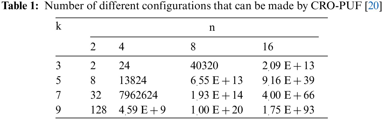
Unlike previous structures, this structure requires a bit of configuration in addition to the challenge bit [22]. Challenge bits can be applied by the user/designer though configuration bits must be applied by the designer so that the ROs are independent of each other and do not interfere with each other. CRO-PUF has made a great upgrade in improving the CRP space and thus increasing the use of RO-PUF by removing RO-PUF from the weak PUFs class and allayed concerns about this structure. On the other hand, since RO-PUF is the structure that has the highest reliability, CRO-PUF makes RO-PUF the most attractive one among other PUF structures. However, the supported CRPs by CRO-PUF are not enough to consider it a strong PUF, fortunately, though the space of the CRO-PUF can be increased non-linearly. In other words, CRPs can be exponentially increased by increasing the number of ROs and columns. The structural weakness of CRO-PUF is mentioned below. Fig. 5a shows an example of different compositions that can be implemented on FPGA by CRO-PUF. Fig. 5b shows a composition that cannot be implemented by CRO-PUF.
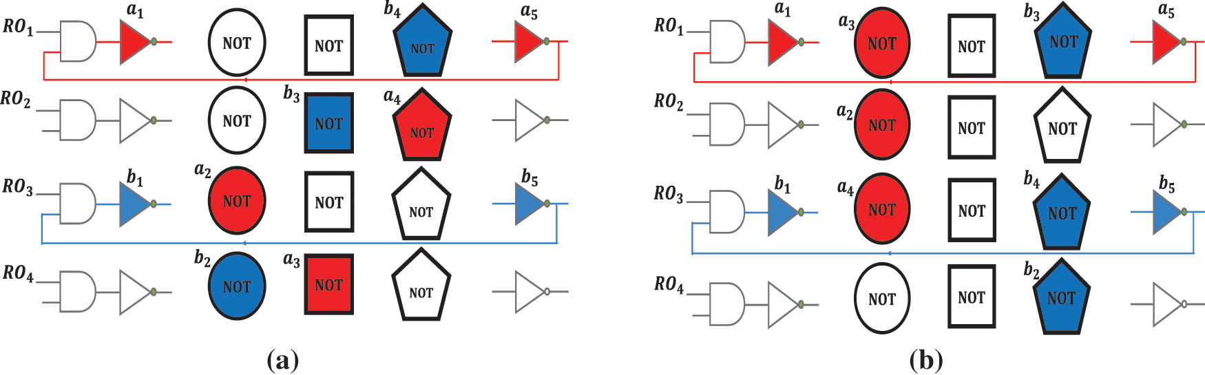
Figure 5: (a) Implementable composition by CRO-PUF; (b) Unimplementable composition by CRO-PUF
The structural weakness of CRO-PUF causes the designer to have limitations on the configuration of each RO and to be forced to choose only one inverter from each column for each RO. As demonstrated in Fig. 5b, the red and blue ROs consist of three circular and three pentagonal inverters, respectively. It is worth mentioning that the depicted composition cannot be implemented with CRO-PUF. If changes to the CRO-PUF structure can provide an improved structure capable of making all possible compositions, the maximum possible CRP will be created for RO-PUF. The result will be a structure with the most flexibility and promises a structure suitable for various security applications.
Increasing the CRP space for RO-PUF is a fundamental need, and many efforts have been done to achieve this goal. RO-PUF is the best and most suitable option for implementation on FPGA and does not have the difficulties of other designs. Based on what was examined in Section 1, it was determined that the structure that provided the best solution was the CRO-PUF structure. In this section first deals with the problems of the CRO-PUF structure. Then, a new structure is proposed based on the CRO-PUF structure and the points that will be made. By comparing the proposed design with the previous designs, the advantages and superiority of the new structure will be determined. In the following, the results of the practical implementation are reviewed to determine the degree of improvement and desirability of the structure under different criteria.
The proposed modified CRO-PUF (MCRO-PUF) structure is shown in Fig. 6. The new block in this structure is called the upper interstage crossing. This block allows the CRO-PUF structure to include the maximum possible configurations by adding spare paths. There are 2n inverters to save hardware in all columns except the first column. In fact, this requires fewer interstage crossings than the CRO-PUF structure, which can be reduced by up to 50% for large structures. It also makes the designer less confused in configuring the structure, while no configuration restrictions will be imposed. Here, Sm is a set of configurations applied to interstage crossing.
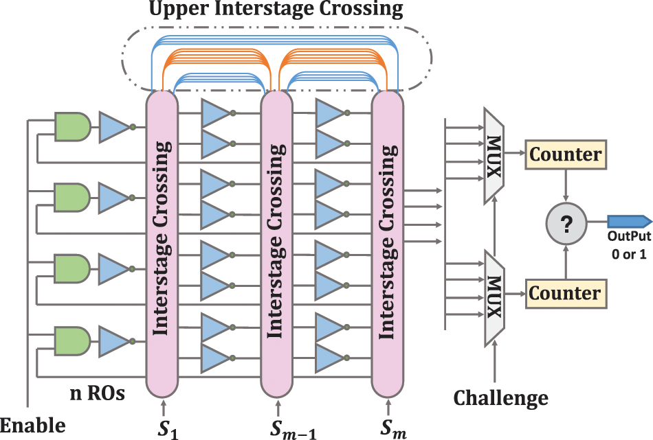
Figure 6: The proposed MCRO-PUF structure
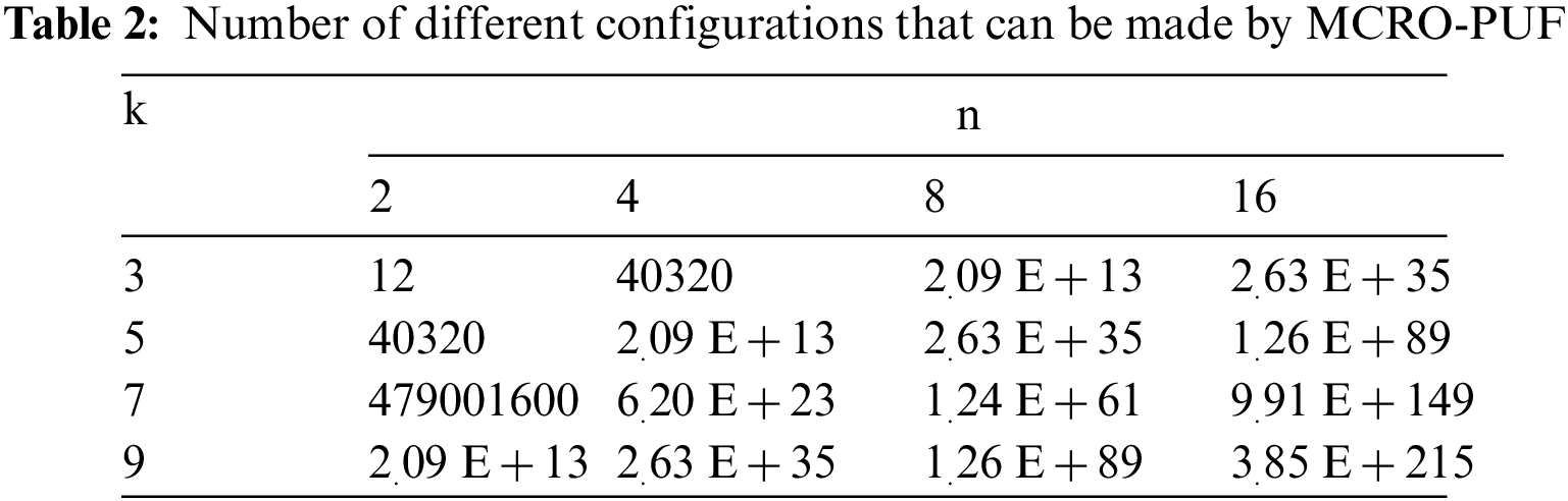
The number of CRPs will be greatly increased by using the structure MCRO-PUF. For this structure, the CRP number will be [n × (k−1)]!.
The number of CRPs in the CRO-PUF structure is (n!)k−2 and k = 2 m−1. With 80 inverters to build 16 RO, the number of CRP of MCRO-PUF is 1.37 × 10+49 times greater than CRO-PUF. This ratio increases exponentially as the number of inverters increases. The only thing the designer has to pay attention to is that he/she should configure it so that all the ROs are formed. Therefore, the designer has a limit on the configuration of n bits of the last interstage crossing unit. This limitation also exists in the CRO-PUF structure, and the configuration of an interstage crossing in the CRO-PUF structure depends on the configuration of other interstage crossings.
Fig. 6 shows more details of the upper interstage crossing. The blue paths are n-bit, and the orange paths are 3/2 n-bits. The blue paths are forward, and the orange paths are backward. As shown in Fig. 6, there are colored paths in this block that allow the arrangement of the columns to be changed. As a result, in addition to increasing RO fabrication modes, it is possible to permutation several specific inverters. Definitely, MCRO-PUF can make the composition of Fig. 5b. By using the upper interstage crossing auxiliary paths, the desired inverters can be selected, and disturbing inverters can be bypassed. Due to these two cases, the CRP space significantly increases, and the proposed MCRO-PUF can be well-considered as a strong PUF. Possible configurations for CRO-PUF and MCRO-PUF are reported in Tables 1 and 2, respectively. By comparing the results of these two tables, the specific ability of the proposed design to increase the CRP space will be revealed.
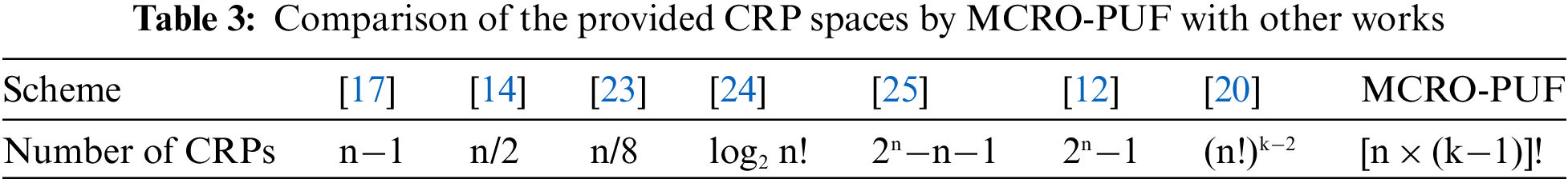
In Table 3, Comparisons between CRP spaces of different PUF designs have been done. The results of this comparison show that the proposed structure is leading, and the hardware cost has been reduced. These benefits are achieved by adding minimal resources.
We have also simulated the proposed structure by the ISE design suite. In this simulation, 80 inverter gates, 8 AND gates, 4 interstage crossing blocks, 2 multiplexer blocks, 2 counter blocks, and 1 comparator have been used. The location attributes have been used to maintain circuital symmetry and create delay paths approximately equal, which leads to increasing the uniqueness and decreasing the predictability of the responses. The purpose of this simulation is to create a structure with sixteen ROs, each RO consisting of five inverters.
4 MCRO-PUF Implementation and Result Evaluation
After the simulation and confirmation of the correct operation of the circuit, the implementation of the proposed design will be implemented on the FGPA board (xc6slx9-2tqg144 chip from the Xilinx Spartan-6 family). To evaluate the performance of MCRO-PUF, a hardware platform including an FPGA board, a temperature sensor, and a computer equipped with ChipScope software is required, as shown in Fig. 7. In order to evaluate the performance of MCRO-PUF, we have used 10000 challenges, and their corresponding responses in different experiments, i.e., the CRPs have been obtained using different chips and under different environmental conditions. To increase the speed of testing and reduce coding operations, ILA, VIO, and ICON IP cores in ISE software have been used to obtain and record the output. The on-board temperature sensor ensures the temperature is set and constant. To measure the structure’s efficiency, the circuit is tested at different temperature conditions. For a more accurate evaluation of reliability, a wide temperature range is considered. Fig. 8 shows the place and route method of MCRO-PUF structure. Due to the equal effect of the number of rows (n) and the number of columns (k) in improving the CRP space, it is possible to create an orbital design with a minimum consumption area. As shown in Fig. 8, the circuit requires a small area. In the following, we will examine the uniqueness, uniformity, and reliability features of the proposed PUF in detail.
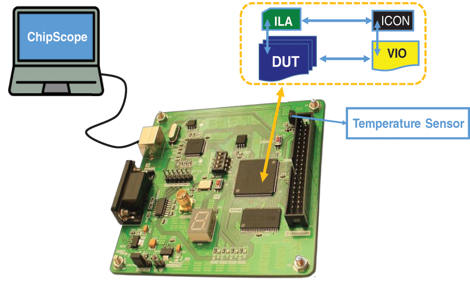
Figure 7: Hardware platform for implementing and testing the proposed structure
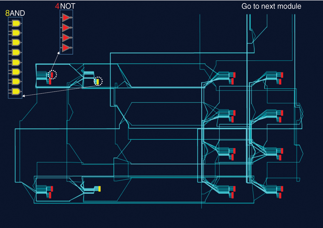
Figure 8: Place and route of ROs of MCRO-PUF structure
Uniqueness is a measure of the difference between the response bits of different PUF instances. In other words, if a particular challenge is applied to two specific PUF instances at the same time and under the same conditions, the responses of the two PUFs must be different. The uniqueness of the proposed PUF is calculated by the average Hamming distance (HD) on 40 different chips. Ri is the n-bit response of the ith chip. For K chips, the inter-HD value is equal to:
Fig. 9 shows the results related to the uniqueness criterion of the proposed structure over the 1280 experiments. The average uniqueness in the responses of the proposed structure has been obtained 48.49%.
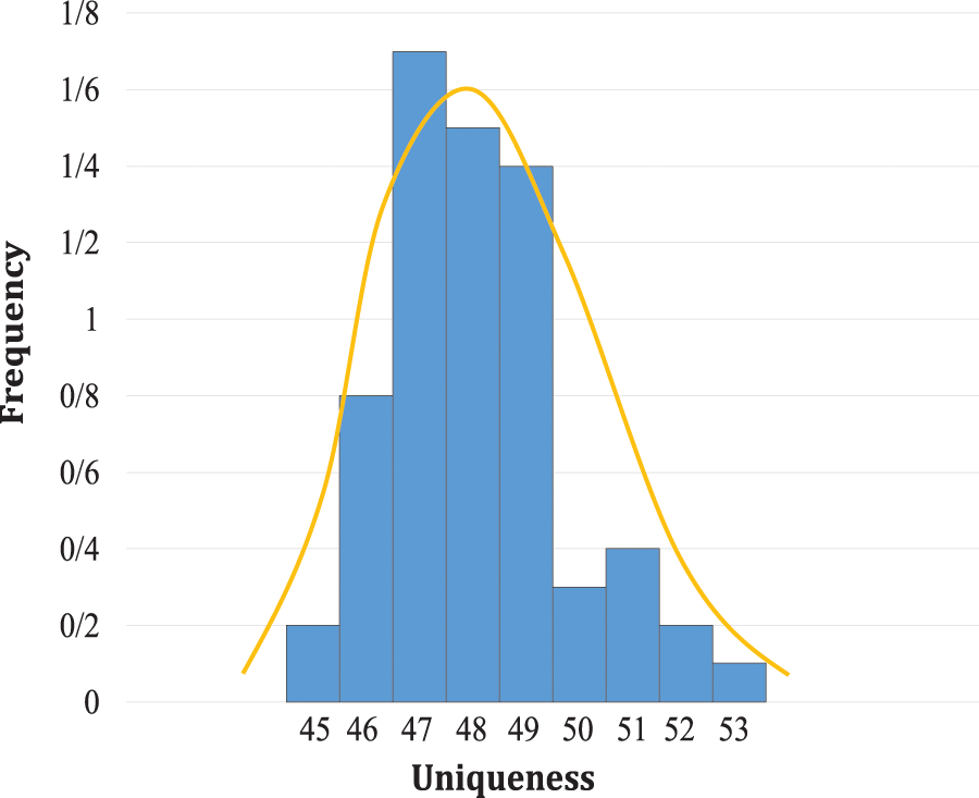
Figure 9: Uniqueness distribution of responses of MCRO-PUF
Uniformity is a measure of the ratio of the number of “1” bits to the total number of response bits. The value of the uniformity value for an ideal PUF is 50%, i.e., 50% of the bits are “1” and the other 50% are “0”. Therefore, the PUF response does not depend on the value of a particular bit [11,15]. Fig. 10 shows the results related to the uniformity of responses. The average number of “1"s in the responses of the proposed structure is 50.99%, which is close to the ideal value of 50%.
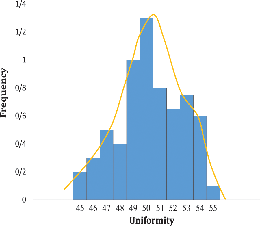
Figure 10: Distribution of “1”s in the MCRO-PUF responses
Reliability is a measure of the stability of the PUF responses in the presence of environmental changes such as temperature variation, voltage changes, and external noises. Assume that Ri is the PUF n-bit response under normal working conditions and R'i is the same PUF response under different working conditions [5,11]. The average intra-HD for the x response from the ith chip is:
Fig. 11 shows the results of the response reliability test. This test is implemented at 10 different temperatures. The specified temperatures include 0°C, 10°C, 20°C, 25°C, 30°C, 40°C, 50°C, 60°C, 70°C, and 80°C. The calculated average reliability is 99.55%, which is very close to the ideal value of 100%. Fig. 11 shows the average reliability at different temperatures. As can be seen, the reliability of the responses generally decreases with increasing the temperature, though, the degree of reliability is not linearly related to temperature, i.e., the reliability may improve with increasing temperature.
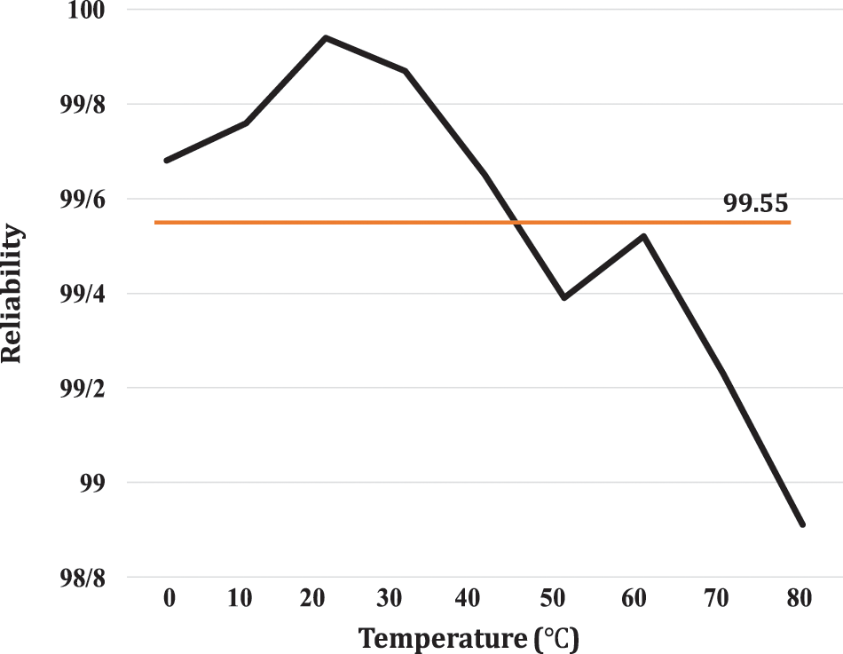
Figure 11: Average reliability of MCRO-PUF at different temperatures
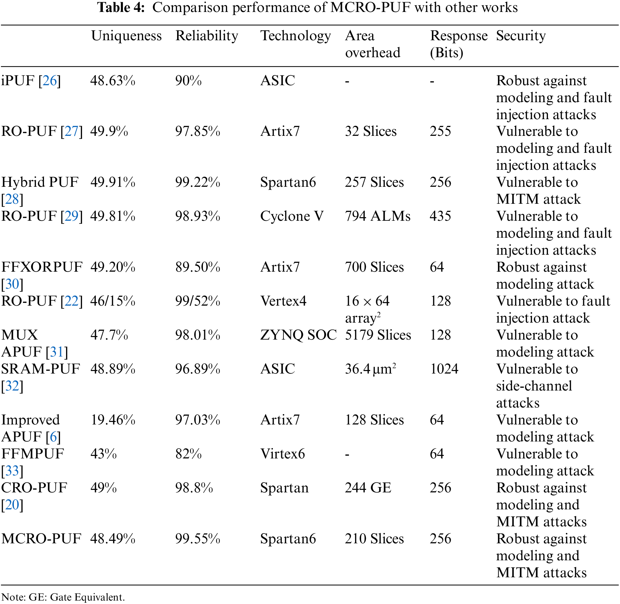
Table 4 compares the different PUF structures with the proposed one in this paper. As can be seen, the proposed structure is a leading structure in total terms of criteria. In this comparison, due to the difficulty of APUF symmetric routing on FPGA, the uniqueness of APUF responses is highly undesirable. The proposed structure is more reliable than CRO-PUF. In addition to increasing the CRP space, the uniqueness of MCRO-PUF is so close to CRO-PUF. Due to the diversity of manufacturing technology and response length, accurately comparison is difficult. However, due to the results of uniqueness, uniformity, and reliability tests, and on the other hand, considering security analysis, CRP space and consumption area, it is concluded that the proposed structure outperforms the state-of-the-art. It can be concluded that the proposed PUF model is the most suitable structure for implementing on FPGA.
This paper proposed a novel strong RO-PUF by highly improving the structure of CRO-PUF. The proposed MCRO-PUF could dramatically increase the supported CRPs. Furthermore, given the resistance of the proposed structure to modeling, side channel and MITM attacks, a promising future for this structure can be envisaged. This structure has also shown a high reliability that is very close to the ideal value, with acceptable uniqueness and uniformity features. In fact, MCRO-PUF could overcome the main drawbacks of the previous RO-PUFs, i.e., the limited CRP space, high hardware cost, and vulnerability to modeling and MITM attacks. This study efficiently presented a plan to address the concern of reducing the hardware cost develop areas for the use of RO-PUF. In addition to the structural benefits of the proposed design, symmetrical implementation is also of particular importance to achieve unpredictable responses and to address any concerns about bias in responses. The experiment results finally proved that the claims made in this study are operational.
Funding Statement: The authors received no specific funding for this study.
Conflicts of Interest: The authors declare that they have no conflicts of interest to report regarding the present study.
References
1. D. Deng, S. Hou, Z. Wang and Y. Gu, “Configurable ring oscillator PUF using hybrid logic gates,” IEEE Access, vol. 8, no. 1, pp. 161427–161437, 2020. [Google Scholar]
2. R. Silwal, “Asynchronous physical unclonable function using FPGA-based self-timed ring oscillator,” M.Sc. Thesis, University of Toledo, USA, 2013. [Google Scholar]
3. B. Habib, “Design, implementation and analysis of efficient FPGA based physical unclonable functions,” Ph.D. Dissertation, George Mason University, USA, 2016. [Google Scholar]
4. N. N. Anandakumar, M. S. Hashmi and M. Tehranipoor, “FPGA-based physical unclonable functions: A comprehensive overview of theory and architectures,” Integration, vol. 81, pp. 175–194, 2021. [Google Scholar]
5. S. Khoshroo, “Design and evaluation of FPGA-based hybrid physically unclonable functions,” M.Sc. Thesis, University of Western Ontario, Canada, 2013. [Google Scholar]
6. C. Gu, W. Liu, Y. Cui, N. Hanley, M. O’Neill et al., “A flip-flop based arbiter physical unclonable function (APUF) design with high entropy and uniqueness for FPGA implementation. IEEE Transactions on Emerging Topics in Computing, vol. 9, no. 4, pp. 1853–1866. 2019. [Google Scholar]
7. H. Gu, “Robust and energy efficient hardware-oriented security for IoT systems and applications,” Ph.D. Dissertation, University of California Los Angles, USA, 2019. [Google Scholar]
8. M. Kaveh, and M. R. Mosavi, “A lightweight mutual authentication for smart grid neighborhood area network communications based on physically unclonable function,” IEEE Systems Journal, vol. 14, no. 3, pp. 4535–4544, 2020. [Google Scholar]
9. M. N. Aman, K. C. Chua and B. Sikdar, “Mutual authentication in IoT systems using physical unclonable functions,” IEEE Internet of Things Journal, vol. 4, no. 5, pp. 1327–1340, 2017. [Google Scholar]
10. M. Kaveh, D. Martín and M. R. Mosavi, “A lightweight authentication scheme for V2G communications: A PUF-based approach ensuring cyber/physical security and identity/location privacy,” Electronics, vol. 9, no. 9, p. 1479, 2020. [Google Scholar]
11. K. Sharad, “Analysis of machine learning modeling attacks on ring oscillator based hardware security,” M.Sc. Thesis, University of Toledo, USA, 2018. [Google Scholar]
12. M. Delavar, S. Mirzakuchaki and J. Mohajeri, “A ring oscillator-based PUF with enhanced challenge-response pairs,” Canadian Journal of Electrical and Computer Engineering, vol. 39, no. 2, pp. 174–180, 2016. [Google Scholar]
13. M. T. Rahman, F. Rahman, D. Forte and M. Tehranipoor, “An aging-resistant RO-PUF for reliable key generation,” IEEE Transactions on Emerging Topics in Computing, vol. 4, no. 3, pp. 335–348, 2015. [Google Scholar]
14. D. Merli, D. Schuster, F. Stumpf and G. Sigl, “Semi-invasive EM attack on FPGA RO-PUFs and countermeasures,” Workshop on Embedded Systems Security, pp. 1–9, 2011. [Google Scholar]
15. J. Zhang, X. Tan, Y. Zhang, W. Wang and Z. Qin, “Frequency offset-based ring oscillator physical unclonable function,” IEEE Transactions on Multi-Scale Computing Systems, vol. 4, no. 4, pp. 711–721, 2018. [Google Scholar]
16. A. Maiti, J. Casarona, L. McHale and P. Schaumont, “A large scale characterization of RO-PUF,” in IEEE Int. Symp. on Hardware-Oriented Security and Trust (HOST), California, USA, pp. 94–99, 2010. [Google Scholar]
17. A. Maiti and P. Schaumont, “Improving the quality of a physical unclonable function using configurable ring oscillators,” in Int. Conf. on Field Programmable Logic and Applications, Prague, Czech Republic, pp. 703–707, 2009. [Google Scholar]
18. M. Gao, L. Khai and Q. Gang, “A highly flexible ring oscillator PUF,” in 51st Annual Design Automation Conf., California, USA, pp. 1–6, 2014. [Google Scholar]
19. A. Maiti and P. Schaumont, “Improved ring oscillator PUF: An FPGA-friendly secure primitive,” Journal of Cryptology, vol. 24, no. 2, pp. 375–397, 2011. [Google Scholar]
20. Z. Pang, J. Zhang, Q. Zhou, S. Gong and X. Qian, “Crossover ring oscillator PUF,” in 18th Int. IEEE Symposium on Quality Electronic Design (ISQED), California, USA, pp. 237–243, 2017. [Google Scholar]
21. J. Zhang and G. Qu, “Physical unclonable function-based key sharing via machine learning for IoT security,” IEEE Transactions on Industrial Electronics, vol. 67, no. 8, pp. 7025–7033, 2019. [Google Scholar]
22. K. Xue, M. Chen, R. Xu, Z. Zhang, Y. Cai et al., “Lightweight and energy-efficient implementation of an unclonable WSN nodes on PSoC,” Journal of Physics: Conference Series, vol. 1622, no. 1, pp. 012126, 2020. [Google Scholar]
23. G. E. Suh and S. Devadas, “Physical unclonable functions for device authentication and secret key generation,” in 44th ACM/IEEE Design Automation Conf., California, USA, pp. 9–14, 2007. [Google Scholar]
24. C. E. Yin and G. Qu, “Obtaining statistically random information from silicon physical unclonable functions,” IEEE Transactions on Emerging Topics in Computing, vol. 2, no. 2, pp. 96–106, 2014. [Google Scholar]
25. A. Maiti, I. Kim and P. Schaumont, “A robust physical unclonable function with enhanced challenge-response set,” IEEE Transactions on Information Forensics and Security, vol. 7, no. 1, pp. 333–34, 2011. [Google Scholar]
26. L. Yu, X. Wang, F. Rahman and M. Tehranipoor, “Interconnect-based PUF with signature uniqueness enhancement,” IEEE Transactions on Very Large Scale Integration, vol. 28, no. 2, pp. 339–352, 2019. [Google Scholar]
27. A. S. Chauhan, V. Sahula and A. S. Mandal, “Novel randomized placement for FPGA based robust ROPUF with improved uniqueness,” Journal of Electronic Testing, vol. 35, no. 5, pp. 581–601, 2019. [Google Scholar]
28. N. N. Anandakumar, M. S. Hashmi and S. K. Sanadhya, “Efficient and lightweight FPGA-based hybrid PUFs with improved performance,” Microprocessors and Microsystems, vol. 77, pp. 103180, 2020. [Google Scholar]
29. Z. Zulfikar, N. Soin, S. F. Wan Muhamad Hatta, M. S. Abu Talip and A. Jaafar, “Routing density analysis of area-efficient ring oscillator physically unclonable functions,” Applied Sciences, vol. 11, no. 20, pp. 9730, 2021. [Google Scholar]
30. S. S. Avvaru, Z. Zeng and K. K. Parhi, “Homogeneous and heterogeneous feed-forward XOR physical unclonable functions,” IEEE Transactions on Information Forensics and Security, vol. 15, pp. 2485–98, 2020. [Google Scholar]
31. S. K. Kulkarni, R. M. Vani and P. V. Hunagund, “A performance comparison between different approaches for implementation of FPGA-based arbiter physical unclonable function,” SCIREA Journal of Electrical Engineering, vol. 7, no. 1, pp. 1–21, 2022. [Google Scholar]
32. J. W. Nam, J. H. Ahn and J. P. Hong, “Compact SRAM-based PUF chip employing body voltage control technique,” IEEE Access, vol. 10, no. 1, pp. 22311–22319, 2022. [Google Scholar]
33. K. Hatti and C. Paramasivam, “Design and implementation of enhanced PUF architecture on FPGA,” International Journal of Electronics Letters, vol. 10, no. 1, pp. 57–70, 2022. [Google Scholar]
Cite This Article
 Copyright © 2023 The Author(s). Published by Tech Science Press.
This work is licensed under a Creative Commons Attribution 4.0 International License , which permits unrestricted use, distribution, and reproduction in any medium, provided the original work is properly cited.
 Downloads
 Citation Tools