
 Submit a Paper
 Propose a Special lssue
 Open Access
ARTICLE

Compact 5G Vivaldi Tapered Slot Filtering Antenna with Enhanced Bandwidth
1 Wireless Communication Centre, Universiti Teknologi Malaysia (UTM), Johor Bahru, Johor, 81310, Malaysia
2 Department of Electronics and Communications Engineering, Faculty of Engineering, Aden University, Aden, 5243, Yemen
3 Center for Wireless Communications, The Institute of Electronics, Communications and Information Technology, Queen’s University Belfast, Northern Ireland Science Park, Queen’s Rd, Queen’s Island, Belfast, Northern Ireland, UK
4 Department of Electrical Engineering, College of Engineering, Jouf University, Sakaka, 72388, Aljouf, Kingdom of Saudi Arabia
* Corresponding Author: Mohd Haizal Jamaluddin. Email:
Computers, Materials & Continua 2023, 74(3), 5983-5999. https://doi.org/10.32604/cmc.2023.035585
Received 26 August 2022; Accepted 26 October 2022; Issue published 28 December 2022
 View Full Text
 Download PDF
Abstract
Compact fifth-generation (5G) low-frequency band filtering antennas (filtennas) with stable directive radiation patterns, improved bandwidth (BW), and gain are designed, fabricated, and tested in this research. The proposed filtennas are achieved by combining the predesigned compact 5G (5.975 – 7.125 GHz) third-order uniform and non-uniform transmission line hairpin bandpass filters (UTL and NTL HPBFs) with the compact ultrawide band Vivaldi tapered slot antenna (UWB VTSA) in one module. The objective of this integration is to enhance the performance of 5.975 – 7.125 GHz filtennas which will be suitable for modern mobile communication applications by exploiting the benefits of UWB VTSA. Based on NTL HPBF, more space is provided to add the direct current (DC) biassing circuits in cognitive radio networks (CRNs) for frequency reconfigurable applications. To overcome the mismatch between HPBFs and VTSA, detailed parametric studies are presented. Computer simulation technology (CST) software is used for the simulation in this study. Good measured S11 appeared to be < −13 and < −10.54 dB at 5.48 – 7.73 and 5.9 – 7.98 GHz with peak realized gains of 6.37 and 6.27 dBi, for VTSA with UTL and NTL HPBFs, respectively which outperforms the predesigned filters. Validation is carried out by comparing the measured and simulated results.Keywords
Fifth-generation (5G) technology has a great impact on the recent wireless communication system offering enhanced, ultra-reliable, and low-latency communication. Federal Communications Commission (FCC) proposed to make 5.97 5 – 7.125 GHz available for unlicensed operations in 5G technology for indoor and outdoor communication with a restriction on the power transmission levels [1].
Due to the important role of antennas and filters in most wireless communication systems, there have been significant efforts to design them with improved performance and reduced size. Bandpass filters (BPFs) are integrated with antennas to reduce the size of the communication system and to address the shortcomings of its receiving antennas, such as poor band-edge selectivity and the presence of undesired harmonics [2]. The filtering concept of integrating a filter with an antenna (co-design) or substituting the last resonator of the filter with an antenna (synthesis strategy) was first proposed in [3,4], respectively. Filtering can also be achieved by etching slots or slits and adding parasitic elements to the antenna [5] which helps in reducing its size. However, they may degrade the antenna performance in terms of gain, polarization polarity, and radiation pattern. On the other hand, using filters is more efficient in controlling the required narrow band with high selectivity and out-of-band rejection levels. Patch [6–11], and monopole [2,12–16] antennas are the most commonly used in the literature for filtering antennas (filtennas design. However, loop [17], dipole [18], quasi-Yagi [19], slot line [20], Vivaldi [21] and Metasurface (MS) [22] antennas are not widely employed. In the next paragraphs, different recent filtennas employing various methodologies from 2015 to 2022 are discussed.
A stacked structure of patch antenna on top and hairpin bandpass filter (HPBF) on the bottom are used in [2] to design a simple compact narrow band filtenna with improved selectivity and efficiency. More practically, compact wearable filtennas with circular polarization suitable for off-body wireless communications are designed in [7,8] by integrating a square patch antenna with an open-loop resonator (OLR) BPF using coupled stripline and pins. High selectivity in filtenna can be achieved using a differential feeding structure [9,10]. In [9], three patches and a line resonator are used to enhance the performance and increase the harmonic suppression level, respectively. However in [10], this structure is applied to mitigate the cross-polarization level and improve the selectivity and out-of-band suppressing levels (−40.1/−39 dB) by integrating a quasi-H-shaped patch (QHSP) and a meandering quasi-T-shaped resonator (QTSR). A 30% size reduction with wide-band harmonic rejection is obtained in [11] by integrating a rectangular stub to the feedline of the ultra-thin fractal patch antenna. The high-frequency selectivity is enhanced in [12,13] by integrating a two-stage split ring resonator (SRR) with circularly and linearly polarized monopole antennas. Authors in [14] proposed compact monopole filtenna with flat gain and high out-of-band rejection level by replacing the second resonator of a square capacitively loaded loop (CLL) BPF with a fan-shaped radiator. Moreover, the bandwidth (BW) of the designed filtenna is enhanced by adding parasitic elements and etching slots in its ground strip. Exploiting the high-order harmonics suppression feature of the interdigital bandpass filter (IBF), it is integrated with a modified elliptic-shaped monopole antenna [2]. Multilayer structure and simple design method are used in [15] to reduce the size of the proposed Γ-shaped monopole filtenna while increasing its selectivity and out-of-band rejection levels. Authors in [16], designed a compact 2.4 GHz printed monopole filtenna for Wi-Fi application, by replacing the second resonator of a square open loop resonator (SOLR) filter with an inverted L-shape monopole antenna. In this design, a quarter-wave admittance inverter with a characteristic impedance other than 50 Ω is used to mitigate the effect of impedance mismatching.
To improve the impedance matching, gain performance and band-edge selectivity, a rectangular loop antenna with high directivity and lower band-edge selectivity is combined with a parasitic strip and loop in [17]. However, a bazooka balun (86 mm) is required to connect the antenna’s bent dipole which increases its size in the Z-direction. Filtenna with high-order harmonics suppression is proposed in [18] using stepped-impedance dipole (SID), stepped-impedance resonator (SIR), and lowpass filter (LPF). A quasi-Yagi filtenna with good filter response and low cross-polarization is designed in [19] using a metallic shielded load-insensitive multimode balun filter. Authors in [20], proposed a filtenna with enhanced BW, selectivity, and flat gain responses by integrating multimode stub-loaded resonators into the slotline antenna. In [21], to enhance and control the Vivaldi antenna performance, a parasitic element with slits and BPF are added, respectively. Also, coplanar parasitic patches are added to the MS antenna to improve the BW, gain, and efficiency of the proposed filtenna in [22]. Recently in [23], spoof surface plasmon polaritons are used to enhance the gain and BW of the proposed leaky wave end fire filtenna using multiple radiating elements, one double-sided parallel strip line, and stubs with via holes for filtering purposes.
Based on frequency or pattern reconfigurable technology, the communication system’s filtering process can be easily controlled, and the number of utilized antennas can be reduced. Recent works on frequency reconfigurable antennas for 5G wireless and cubeSat application, pattern reconfigurable patch antennas for mid-band 5G applications, and flexible frequency-reconfigurable antenna for global system for mobile communication (GSM), fourth generation long-term evolution (4G-LTE), industrial, scientific and medical (ISM), and 5G Sub-6 GHz band applications can be found in [24–26], respectively.
In this work, the predesigned 6.55 GHz uniform and non-uniform transmission line (UTL) and (NTL) HPBFs in [27,28], respectively are integrated with the predesigned compact ultrawide band Vivaldi tapered slot antenna (UWB VTSA) in [29] to design compact 5G Vivaldi tapered slot filtering antennas (VTSFAs). This integration aims to suppress the unwanted signals and exploit the good performance of VTSA in terms of BW, gain, and stable directive radiation patterns. As a result of integrating UTL HPBF and NTL HPBF into VTSA, their BW is enhanced by 0.27 and 0.22 GHz, respectively. In addition to this section, Section 2, explains the design and analysis of the proposed filtennas, as well as the parametric studies. The results are discussed in Section 3.
To keep up with the recent development in the wireless communication system, the proposed VTSFAs are chosen to work in the 5G low-frequency band (5.975 – 7.125 GHz). Based on the co-design approach, the designed 6.55 GHz UTL and NTL HPBFs in [27,28], respectively are integrated into the feed line of the recently designed compact UWB VTSA [29] resulting in 6.55 GHz VTSFA using 6.55 GHz UTL HPBF (Antenna 1) and NTL HPBF (Antenna 2).
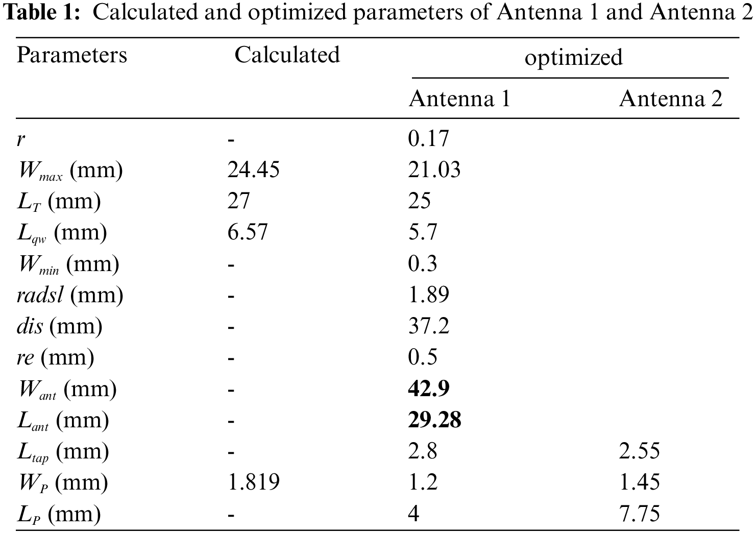
The main reason for integrating the 6.55 GHz filters with UWB VTSA is to provide a small size filtenna with wide BW where the design frequency for the UWB VTSA (6.85 GHz) is higher than that of the filter (6.55 GHz). In addition, this integration will be suitable for 5G low-frequency band/UWB reconfigurable antenna applications such as cognitive radio networks (CRNs). The idea behind integrating the 6.55 GHz NTL HPBF into the antenna is to provide a larger space due to the 17.76% resonators’ length reduction in NTL HPBF using NTLs theory [28]. As compared to Antenna 1, this small additional space will help in adding more components as explained in the proposed 5G low-frequency band/UWB reconfigurable antenna in [30] where switching diodes and the direct current (DC)-biasing circuits (DC-blocking capacitors, biasing inductors, biasing lines, and pads) are added. The Substrate material in this study is chosen to be Rogers RO4003C (with dielectric constant (Ɛr) = 3.55, height (h) = 0.813 mm, dielectric loss tangent of 0.0027, and copper thickness = 0.035 mm). The VTSA and both filters are designed at 3.1 – 10.6 GHz and 5.975 – 7.125 GHz with center frequencies, FC = 6.85, and 6.55 GHz, respectively. Both filters are designed based on the procedure and design equations explained in [31] using Chebyshev lowpass prototype with a passband ripple of 0.1 dB and g0 = g4 = 1, g1 = g3 = 1.0316, g2 = 1.1474. Sections 2.1 and 2.2 discuss the design and analysis with detailed parametric studies for Antenna 1 and Antenna 2, respectively. The selected optimized parameters for the proposed filtennas are in a red solid line.
The ability of VTSA to be integrated with circuits without affecting its overall performance is demonstrated here through parametric studies on Antenna 1 as illustrated in Fig. 1. All the parameters of UWB VTSA are similar to that in [29]. Also, most of the HBPF parameters are not changed except the tapping length, Ltap, and the position from the feeding point, Lp. In Fig. 1, r, LT, Lqw, Wmin, Wmax, Wp, radsl, Want, Lant, and dis are the magnification rate, taper length, quarter wavelength, aperture opening, aperture width, feeding port width, radius of slot, antenna width, antenna length, remaining distance of Want without Lqw, respectively. The exponential taper slot of VTSA according to [32] can be defined by
where A = 0.5 *Wmin and x is the position along LT
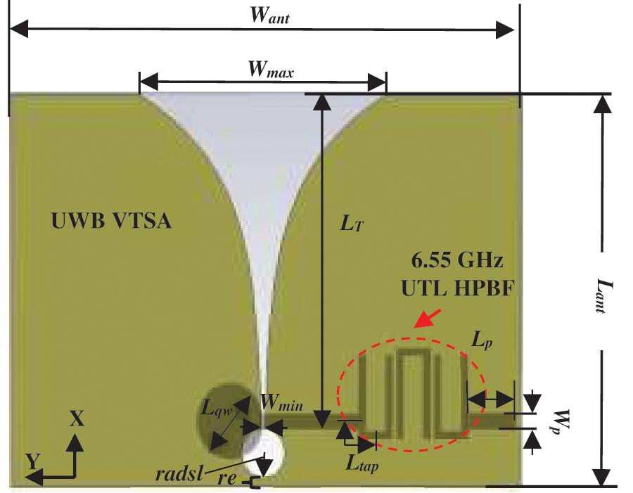
Figure 1: The configuration of Antenna 1
The main characteristics of Antenna 1 are similar to [29], and the best matching within the required BW and moderate gain (S11 < – 11.82 dB, BW = 5.976 – 7.656 = 1.68 GHz and maximum realized gain of 6.45 dBi) is obtained at r = 0.17, LT = 25 mm, Lqw = 5.7 mm, Wmin = 0.3 mm, radsl = 1.89 mm, dis = 37.2 mm and Wp = 1.2 mm. The effect of changing r, LT, Wmin, radsl, dis, and Wp on the performance of Antenna 1 in terms of S11 and gain is illustrated in Figs. 2a–2f, respectively. Fig. 2f demonstrates that the Wp = 1.2 mm used for UWB VTSA is better than that at Wp = 1.819 mm (S11 < – 10 dB, BW = 6.4 – 7.22 = 0.82 GHz and maximum realized gain of 6.17 dBi) utilized for UTL HPBF [27] and Wp = 1.5095 mm (S11 < – 11.67 dB, BW = 6.1 – 7.41 = 1.31 GHz and maximum realized gain of 6.38 dBi) in terms of matching, BW, and gain. At Wp < 1.2 mm, there is a noticeable mismatch, such as at Wp = 0.8905 mm (S11 < – 6.7 dB, BW = 5.976 – 7.72 = 1.744 GHz and maximum realized gain of 6.79 dBi). For better matching, two important parameters related to the filter side are changed, Ltap and Lp as shown in Figs. 2g and 2h, respectively. Fig. 2g shows that although the matching and gain at the optimized value, Ltap = 2.9 mm (S11 < – 12.9 dB, BW = 6.04 – 7.62 = 1.58 GHz and maximum realized gain of 6.53 dBi) for UTL HPBF [27] are 8.37% and 1.23% better than that at Ltap = 2.8 mm (S11 < – 11.82, BW = 5.976 – 7.656 = 1.68 GHz and maximum realized gain of 6.45 dBi), it is selected due its 5.95% wider BW which covers the lower frequency in required band (5.975 – 7.125 GHz). As indicated in Fig. 2h for good matching, the best position from the feed line is at LP = 4 mm (S11 < −11.82 dB), which is better than that at LP = 2 mm (S11 < – 11.24 dB), LP = 3 mm (S11 < – 11.49 dB), and LP = 5 mm (S11 < – 9.66 dB).
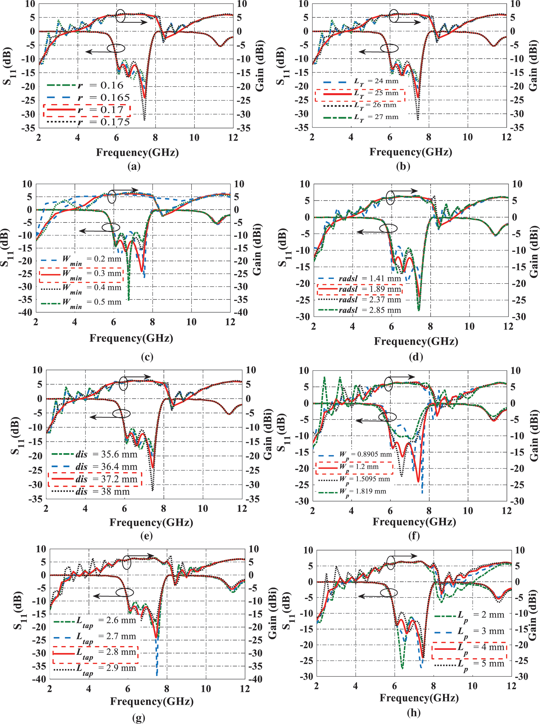
Figure 2: S11 and gain parametric study of Antenna 1 on (a) r, (b) LT, (c) Wmin, (d) radsl, (e) dis, (f) Wp, (g) Ltap and (h) Lp
By applying the NTL theory [28] to the designed 6.55 GHz UTL HPBF in [27], the UTL resonators are replaced by their equivalent NTL resonators with a 17.76% size reduction, guaranteeing that their ABCD parameters are equal. Fig. 3 shows how to get the ABCD parameters of NTL by dividing it into K UTLs and then finding their ABCD parameters, so the total ABCD matrix will be
where
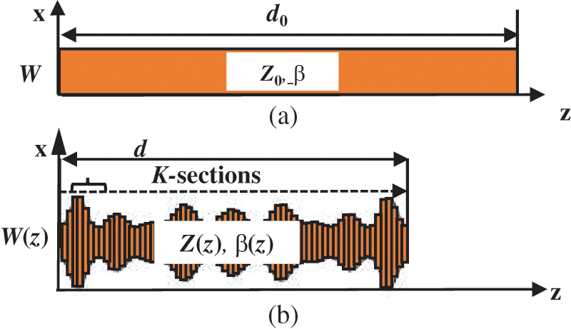
Figure 3: UTL with its equivalent NTL
where c is the speed of light and Z(z) is the NTL’s variable characteristics impedance which can be expanded in a truncated Fourier series as follows
where
where M is the number of the frequencies fm (m = 1, 2, . . . M) within the desired band with a frequency increment Δf and A0, B0, C0 and D0 are the ABCD matrix parameters of UTL.
The compact NTL HPBF in Antenna 2 depicted in Fig. 4, provides more space for the DC biassing circuits in CRNs applications. And here the optimized r = 0.17 mm, LT = 25 mm, Lqw = 5.7 mm, Wmin = 0.3 mm, radsl = 1.89 mm, dis = 37.2 mm, and Wp = 1.2 mm are similar to [29] with S11 < – 12.36 dB through 5.968 – 7.643 GHz (BW = 1.675 GHz) and maximum realized gain of 6.47 dBi. The parametric studies on Lqw, Wmin, radsl, and Wp are shown in Figs. 5a–5d, respectively. Also here, the suitable Wp to match HPBF with the antenna feed line is at Wp = 1.2 mm (S11 < – 12.36 dB, BW = 5.968 – 7.643 = 1.675 GHz and maximum realized gain of 6.47 dBi) that is better than WP = 1.819 mm (S11 < – 7 dB, BW = 5.93 – 7.57 = 1.64 GHz and maximum realized gain of 6.45 dBi) as illustrated in Fig. 5d. The optimized Ltap = 2.55 mm as shown in Fig. 5e is better than that at Ltap = 2.9 mm (S11 < – 10.99 dB, BW = 6.07 – 7.535 = 1.465 GHz and maximum realized gain of 6.37 dBi) in terms of matching, BW and gain. At Ltap < 2.55 mm, the S11 value is degrading as at Ltap = 2.2 mm (S11< −10.535 dB) and Ltap = 1.85 mm (S11 < – 7.51 dB). Finally, Fig. 5f shows that due to the reduction in NTL HPBF size, the best feeding position is at LP = 7.75 mm which is greater than that at LP = 4 mm for UTL HPBF (Fig. 2f) in Antenna 1 and better than other values such as at LP = 4.75 mm (S11 <–10 dB, BW = 6.64 – 7.3 = 0.66 GHz and maximum realized gain of 6.28 dBi), LP = 5.75 mm (S11 < – 9.77 dB, BW = 6.08 – 7.36 = 1.28 GHz and maximum realized gain of 6.31 dBi) and LP = 6.75 mm (S11 < – 11.07 dB, BW = 5.99 – 7.42 = 1.43 GHz and maximum realized gain of 6.33 dBi) in terms of matching, BW and gain. Fig. 6 illustrates the prototypes of the proposed VTSFAs which are fabricated based on optimized parameters in Table 1. The size of the proposed filtennas is equal to 42.9 × 29.28 mm2.
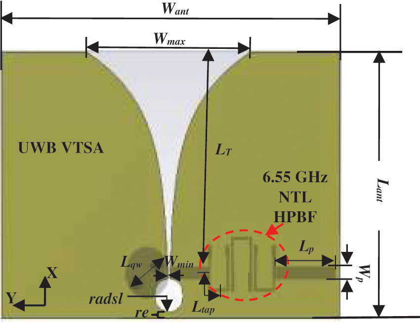
Figure 4: The configuration of Antenna 2
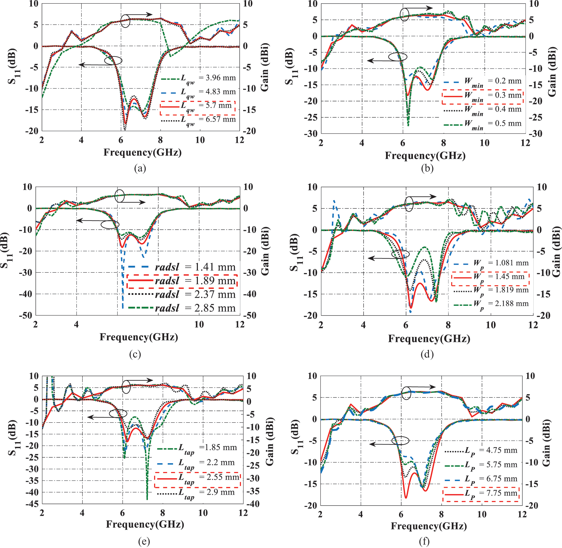
Figure 5: S11 and gain parametric study of Antenna 2 on (a) Lqw, (b) Wmin, (c) radsl, (d) Wp, (e) Ltap, and (f) Lp
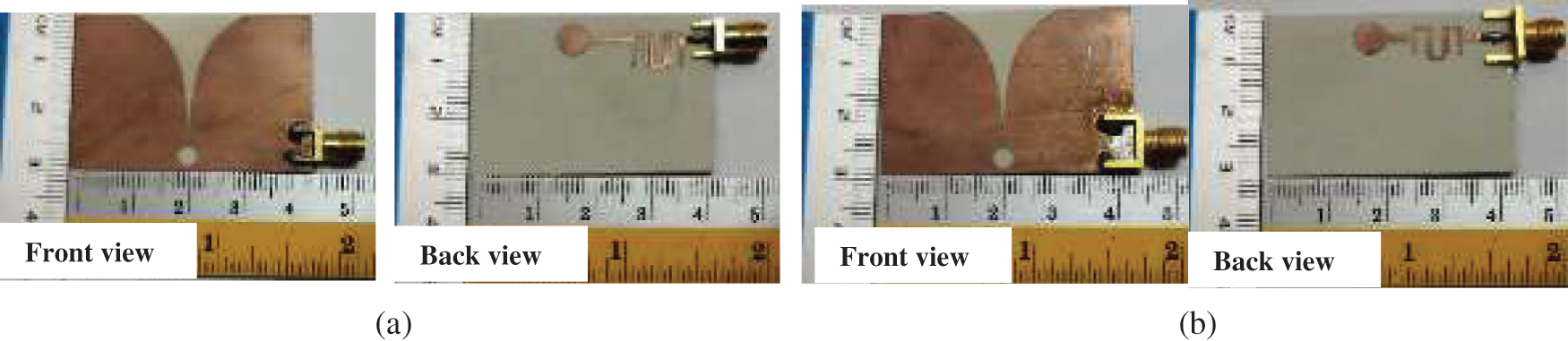
Figure 6: Fabricated prototype of (a) Antenna 1 and (b) Antenna 2
As shown from Fig. 7, in addition to the small circuit area and stable directive radiation patterns provided due to the use of UWB VTSA [29], Antenna 1 (Meas.: S11 < −13 dB at 5.48–7.73 GHz, BW = 2.25 GHz) and Antenna 2 (S11 <–10.54 dB at 5.9–7.98 GHz, BW = 2.08 GHz) in this work provide enhanced BW by 0.27 and 0.22 GHz than the 6.55 GHz UTL HPBF (Meas.: S11 <–11.66 dB at 5.62–7.6 GHz, BW = 1.98 GHz) [27] and 6.55 GHz NTL HPBF (Meas.: S11 <–22.26 dB at 5.924–7.523 GHz, BW = 1.86 GHz) [28], respectively. The simulated and measured results for both filtennas are illustrated in Table 2 in terms of S11, voltage standing wave ratio (VSWR), peak realized gain, and total radiation efficiency. As illustrated in Table 2 and Figs. 8a and 8b, Antenna 1 and Antenna 2 provide good measured input matching less than −13 dB (Sim. <–11.82 dB) and −10.54 dB (Sim.<–12.63 dB) with a BW wider than the 5G low frequency band (5.975–7.125 GHz) by 48.89% (Sim. = 31.55%) and 44.71% (Sim. = 31.34%), respectively. These good results make the 6.55 GHz VTSFAs suitable for the recent wireless communication system applications especially CRNs using NTL HPBF in Antenna 2 when more space is required for the DC-biasing circuits. Due to the introduced reflection losses, the realized gain is considered in this work, and it is measured using the gain transfer method. Figs. 8a and 8b also show that Antenna 1 and Antenna 2 provide a maximum measured realized gain of 6.37 dBi (Sim. = 6.43 dBi) and 6.27 dBi (Sim. = 6.47 dBi), respectively. As noticed that measured maximum gain provided by Antenna 1 (using UTL HPBF) is 1.57% higher than that of Antenna 2 (using NTL HPBF). These good results reflect the effectiveness of integrating the predesigned UTL and NTL HPBFs with UWB VTSA without degrading the resulting filtennas’ performance. The good measured total radiation efficiencies provided by Antenna 1 and Antenna 2 are between 60.4% and 96.9% (Sim. = 63.95% and 98.43%) and 62.54% and 91.92% (Sim. = 63.19% and 93.16%), respectively as shown in Fig. 9. As indicated in Fig. 10a, the real and imaginary parts of the simulated input impedance reflect good matching between the antenna microstrip feedline and 50 Ω SMA connector in which they are oscillating around 50 and 0 Ω, respectively. Due to the longer path that the signal will take passing through the UTL HPBF in Antenna 1, it is leading the NTL HPBF in Antenna 2 as depicted in Fig. 10b. The discrepancy between the simulated and measured results is due to the fabrication tolerance, the imperfect soldering of SMA connectors, and the difference between the simulation and real measurement environments where a numerical technique (Finite Integration Technique (FIT) in Computer simulation technology (CST) software) is used to approximate the fields within certain boundary conditions.
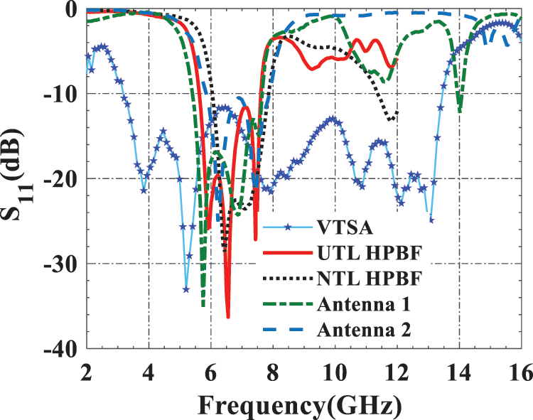
Figure 7: Measured S11 of Antenna 1 and Antenna 2 as compared to UWB VTSA [29], 6.55 GHz UTL HPBF [27] and NTL HPBF [28]
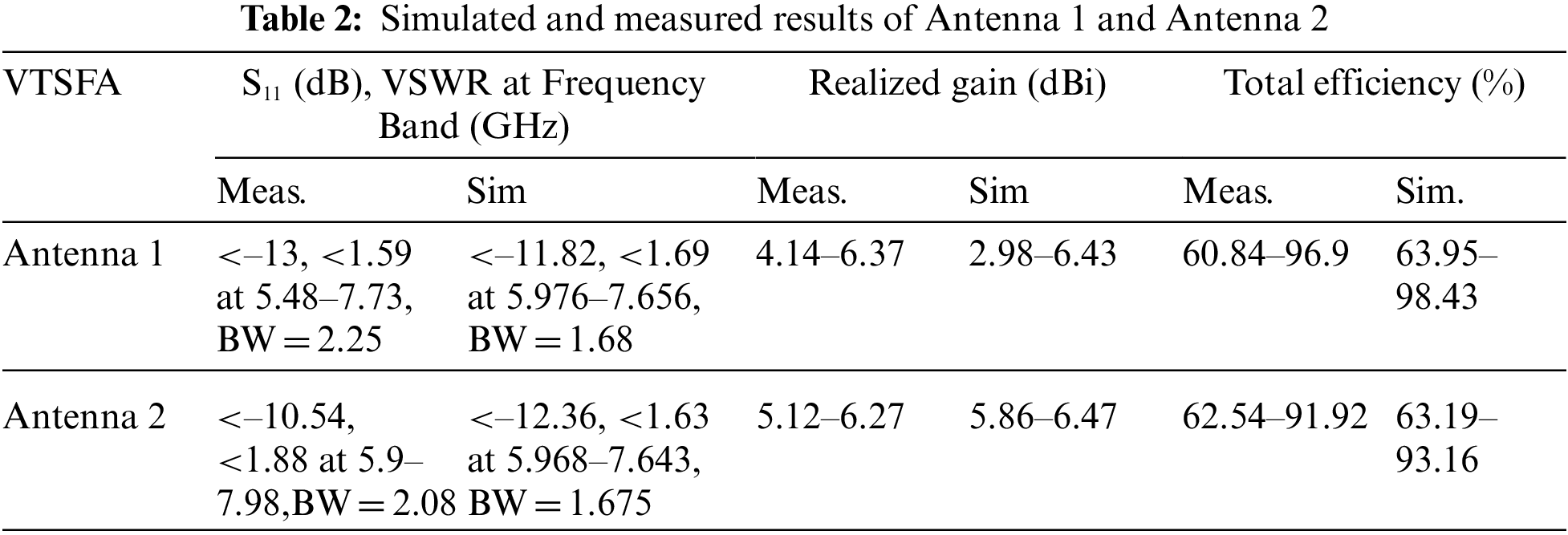
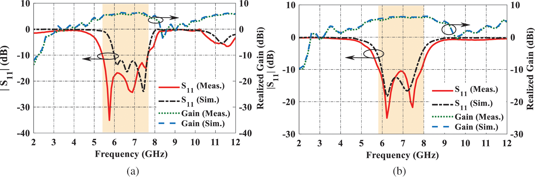
Figure 8: Measured and simulated S11 and gain of (a) Antenna 1 and (b) Antenna 2
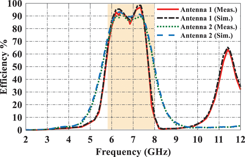
Figure 9: Measured and simulated total efficiency of Antenna 1 and Antenna 2
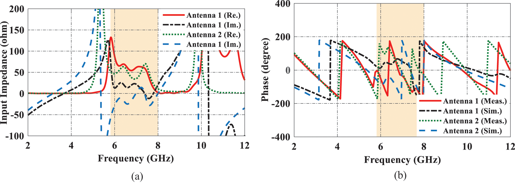
Figure 10: (a) Simulated input impedance and (b) measured and simulated phase of Antenna 1 and Antenna 2
Figs. 11a–11f show the normalized 2-D polar plots of the E-plane (XY-plane) and H-plane (XZ-plane) radiation patterns at f = 6, f = 6.85 and f = 7.35 GHz, respectively for both filtennas. As it is clear from Fig. 11, both filtennas provide stable directive end-fire E-plane and dipole H-plane radiation patterns similar to the designed compact UWB VTSA in [29]. The discrepancy between the simulated and measured radiation patterns is due to fabrication errors and measurement tolerance.
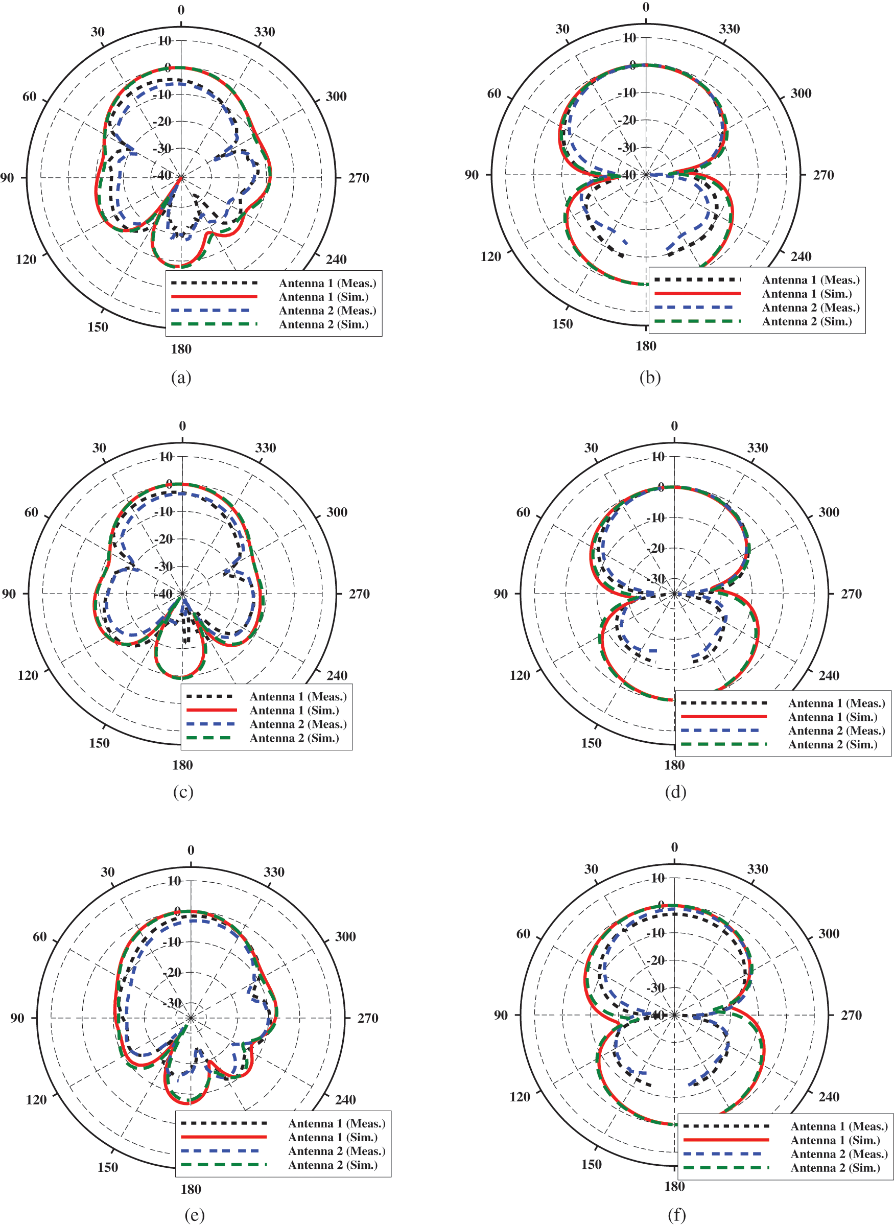
Figure 11: Measured and simulated radiation patterns of Antenna 1 and Antenna 2 at f = 6 GHz (a) E and (b) H, f = 6.85 GHz (c) E and (d) H, f = 7.35 GHz (e) E and (f)
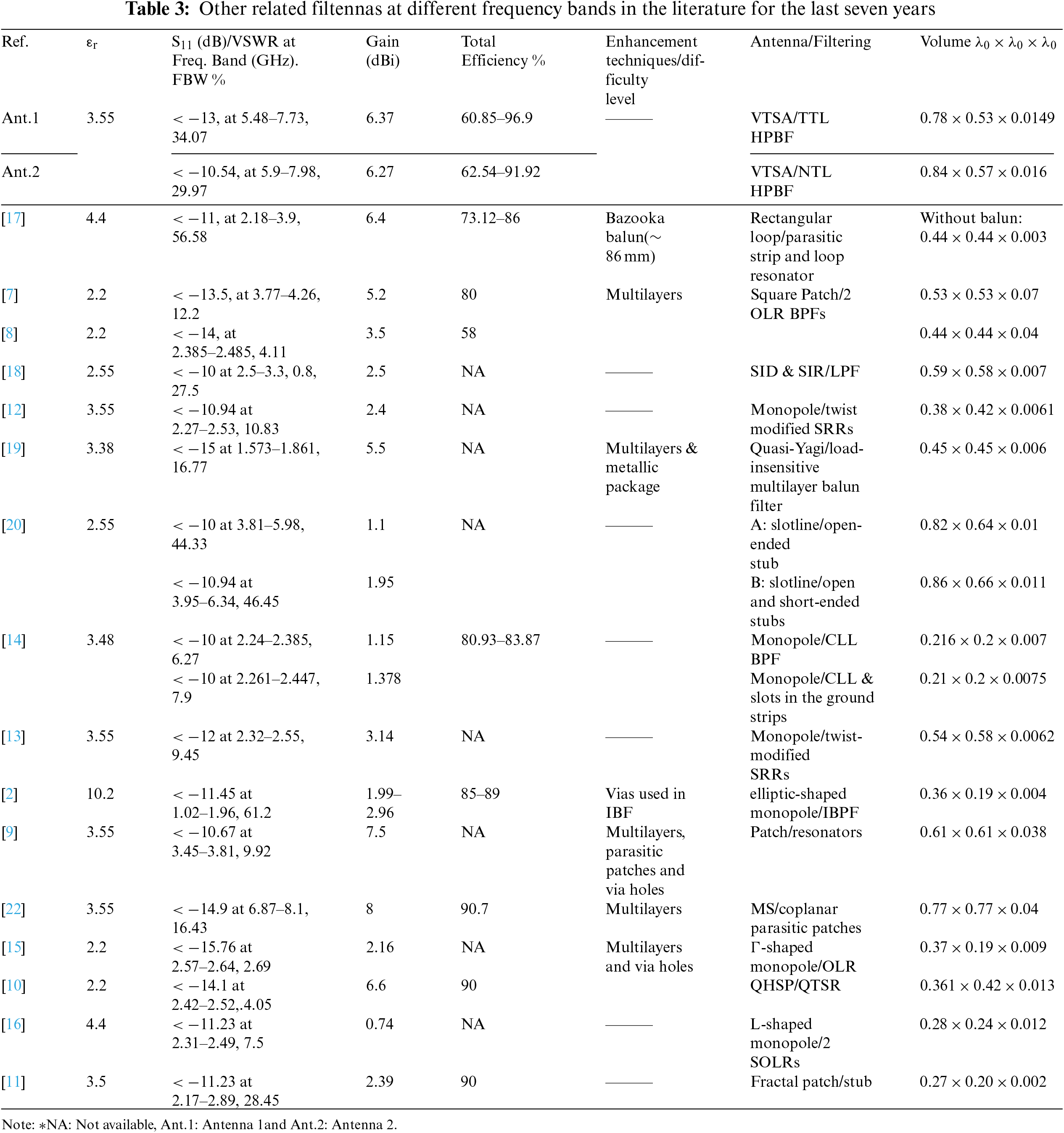
Finally,Table 3 compares the proposed single-band planar filtennas to the closed ones in the literature for the last seven years. Avoiding the difficulties of using multilayers in [7,8], Antennas 1 and 2 provide 68.69% and 20.51% and 61.04% and 1.07% volume reductions with 64.19% and 59.29% and 87.94% and 82.29% wider fractional BW (FBW), respectively. Moreover, they provide 18.37% and 17.07% and 45.05% and 44.18% higher maximum gain and 17.44% and 12.97% and 12.28% and 7.53% efficiency enhancement, respectively. In addition to the easy integration of the proposed filtennas, 56.44% and 45.82% and 74.03% and 69.7% volume reductions with 70.88% and 66.9% and 51.78% and 45.18% FBW enhancement are obtained for Antenna 1 and Antenna 2 as compared to the proposed ones in [9,22], respectively. As compared to Antenna 1, although the FBW provided in [19] (Antenna B) is enhanced by 26.65%, Antenna 1 provides a 1.47% volume reduction and 69.38% gain enhancement. Despite of larger size of the proposed filtennas, they simply provide enhanced maximum gain with efficiency and enhanced FBW with efficiency than [2,10] avoiding the difficulty of using via holes and multilayers with via holes, respectively. Despite the smaller size of filtennas in [11–16,18,19], their achieved FBW and maximum gain as compared to Antenna 1 are smaller by 16.50% and 62.84%, 68.21% and 62.32%, 73.17% and 50.71%, 81.6% and 81.95%, 77.99% and 83.38%, 19.28% and 60.75%, 50.78% and 13.66%, and 91.25% and 66.09% respectively. It should be noted that, despite the better FBW and gain offered by [17], it still requires a bazooka balun of around 86 mm, increasing its final size in the Z-direction.
This paper explains how to combine a predesigned compact UWB VTSA simply and effectively with 6.55 GHz UTL and NTL HPBFs to create two compact VTSFAs suitable for modern wireless communication applications such as CRNs. The use of UWB VTSA helps in providing stable directive radiation patterns and enhanced BW and gain. Furthermore, its ease of integration with other circuits is exploited in this work to achieve good matching and prevent the requirement for external matching components. The proposed filtennas provide good results in terms of matching, enhanced BW, and moderate maximum gain. Future work may include applying this co-design approach to the compact version of VTSA using NTL theory at different frequency bands with different BPFs.
Funding Statement: This work was supported by the Postdoctoral Fellowship Scheme under the Professional Development Research University from Universiti Teknologi Malaysia (UTM) under Grant 06E07.
Conflicts of Interest: The authors declare that they have no conflicts of interest to report regarding the present study.
References
1. “5G Spectrum Vision,” White paper. 5G Americas, Bellevue, Washington, pp. 1–50, 2019. [Google Scholar]
2. B. Sahu, S. Singh, M. K. Meshram and S. P. Singh, “Integrated design of filtering antenna with high selectivity and improved performance for L-band applications,” AEU-International Journal of Electronics and Communications, vol. 97, pp. 185–194, 2018. [Google Scholar]
3. H. An, B. Nauwelaers and A. van de Capelle, “A new approach of broadband microstrip antenna design,” in IEEE Antennas and Propagation Society (APS) Int. Symp., Chicago, IL, USA, pp. 475–478, 1992. [Google Scholar]
4. A. Abbaspour-Tamijani, J. Rizk and G. Rebeiz, “Integration of filters and microstrip antennas,” in IEEE Antennas and Propagation Society (APS) Int. Symp., San Antonio, TX, USA, pp. 874–877, 2002. [Google Scholar]
5. A. K. Gangwar, M. S. Alam, V. Rajpoot and A. K. Ojha, “Filtering antennas: A technical review,” International Journal of RF and Microwave Computer-Aided Engineering, vol. 31, no. 10, pp. 1–31, 2021. [Google Scholar]
6. C. X. Mao, S. Gao, Z. P. Wang, Y. Wang, F. Qin et al., “Integrated filtering-antenna with controllable frequency bandwidth,” in European Conf. on Antennas and Propagation ( EuCAP), Lisbon, Portugal, pp. 5–8, 2015. [Google Scholar]
7. Z. H. Jiang and D. H. Werner, “A compact, wideband circularly polarized co-designed filtering antenna and its application for wearable devices with low SAR,” IEEE Transactions on Antennas and Propagation, vol. 63, no. 9, pp. 3808–3818, 2015. [Google Scholar]
8. Z. H. Jiang, M. D. Gregory and D. H. Werner, “Design and experimental investigation of a compact circularly polarized integrated filtering antenna for wearable biotelemetric devices,” IEEE Transactions on Biomedical Circuits and Systems, vol. 10, no. 2, pp. 328–338, 2016. [Google Scholar]
9. W. Wang, J. Ran, N. Hu, W. Xie, Y. Wu et al., “A novel differential filtering patch antenna with high selectivity,” International Journal of RF and Microwave Computer-Aided Engineering, vol. 29, no. 10, pp. 1–10, 2019. [Google Scholar]
10. Z. Zheng, D. Li, X. Tan, M. Wang and Y. Deng, “Compact low-profile differential filtering microstrip patch antenna with high selectivity and deep rejection using single-layer substrate,” IEEE Access, vol. 9, pp. 76047–76055, 2021. [Google Scholar]
11. W. A. Awan, N. Hussain and T. T. Le, “Ultra-thin flexible fractal antenna for 2.45 GHz application with wideband harmonic rejection,” AEU-International Journal of Electronics and Communications, vol. 110, pp. 152851, 2019. [Google Scholar]
12. W. Cheng, “Compact 2.4-GHz filtering monopole antenna based on modified SRR-inspired high-frequency-selective filter,” Optik, vol. 127, no. 22, pp. 10653–10658, 2016. [Google Scholar]
13. W. Cheng and D. Li, “Compact filtering monopole antennas based on the miniaturized coupled filter,” in Cross Strait Quad-Regional Radio Science and Wireless Technology Conf., (CSQRWC), Xuzhou, China, pp. 15–17, 2018. [Google Scholar]
14. M. C. Tang, Y. Chen and R. W. Ziolkowski, “Experimentally validated, planar, wideband, electrically small, monopole filtennas based on capacitively loaded loop resonators,” IEEE Transactions on Antennas and Propagation, vol. 64, no. 8, pp. 3353–3360, 2016. [Google Scholar]
15. J. Cui, A. Zhang and S. Yan, “Co-design of a filtering antenna based on multilayer structure,” International Journal of RF and Microwave Computer-Aided Engineering, vol. 30, no. 2, pp. 1–6, 2020. [Google Scholar]
16. P. Pal, R. Sinha and S. K. Mahto, “Synthesis approach to design a compact printed monopole filtenna for 2.4 GHz Wi-fi application,” International Journal of RF and Microwave Computer-Aided Engineering, vol. 31, no. 5, pp. 2–9, 2021. [Google Scholar]
17. J. Wu, Z. Zhao, Z. Nie and Q. H. Liu, “A printed unidirectional antenna with improved upper band-edge selectivity using a parasitic loop,” IEEE Transactions on Antennas and Propagation, vol. 63, no. 4, pp. 1832–1837, 2015. [Google Scholar]
18. G. H. Sun, S. W. Wong, L. Zhu and Q. X. Chu, “A compact printed filtering antenna with good suppression of upper harmonic band,” IEEE Antennas and Wireless Propagation Letters, vol. 15, pp. 1349–1352, 2016. [Google Scholar]
19. H. Tang, J. X. Chen, H. Chu, G. Q. Zhang, Y. J. Yang et al., “Integration design of filtering antenna with load-insensitive multilayer balun filter,” IEEE Transactions on Components, Packaging and Manufacturing Technology, vol. 6, no. 9, pp. 1408–1416, 2016. [Google Scholar]
20. H. T. Hu, F. C. Chen and Q. X. Chu, “Novel broadband filtering slotline antennas excited by multimode resonators,” IEEE Antennas and Wireless Propagation Letters, vol. 16, pp. 489–492, 2017. [Google Scholar]
21. K. Yang, M. H. Hoang, X. Bao, P. McEvoy and M. J. Ammann, “Dual-stub Ka-band vivaldi antenna with integrated bandpass filter,” IET Microwaves, Antennas and Propagation, vol. 12, no. 5, pp. 668–671, 2018. [Google Scholar]
22. W. Yang, S. Chen, Q. Xue, W. Che, G. Shen et al., “Novel filtering method based on metasurface antenna and its application for wideband high-gain filtering antenna with low profile,” IEEE Transactions on Antennas and Propagation, vol. 67, no. 3, pp. 1535–1544, 2019. [Google Scholar]
23. W. Feng, Y. Feng, L. S. Wu, Y. Shi, X. Y. Zhou et al., “A novel leaky wave endfire filtering antenna based on spoof surface plasmon polaritons,” IEEE Transactions on Plasma Science, vol. 48, no. 9, pp. 3061–3066, 2020. [Google Scholar]
24. K. Ramahatla, M. Mosalaosi, A. Yahya and B. Basutli, “Multiband reconfigurable antennas for 5G wireless and CubeSat applications: A review,” IEEE Access, vol. 10, pp. 40910–40931, 2022. [Google Scholar]
25. S. R. Isa, M. Jusoh, T. Sabapathy, J. Nebhen, M. R. Kamarudin et al., “Reconfigurable pattern patch antenna for mid-band 5G: A review,” Computers, Materials and Continua, vol. 70, no. 2, pp. 2699–2725, 2022. [Google Scholar]
26. W. A. Awan, N. Hussain, S. Kim and N. Kim, “A Frequency-reconfigurable filtenna for GSM, 4G-LTE, ISM, and 5G Sub-6 GHz band applications,” Sensors, vol. 22, no. 15, pp. 5558, 2022. [Google Scholar]
27. S. Saleh, W. Ismail, I. S. Zainal Abidin and M. H. Jamaluddin, “5G hairpin and interdigital bandpass filters,” International Journal of Integrated Engineering, vol. 12, no. 6, pp. 71–79, 2020. [Google Scholar]
28. S. Saleh, W. Ismail, I. S. Zainal Abidin and M. H. Jamaluddin, “Compact 5G hairpin bandpass filter using non-uniform transmission lines theory,” Applied Computational Electromagnetics Society Journal, vol. 36, no. 2, pp. 126–131, 2021. [Google Scholar]
29. S. Saleh, W. Ismail, I. S. Zainal Abidin, M. H. Jamaluddin, M. H. Bataineh et al., “Compact UWB vivaldi tapered slot antenna,” Alexandria Engineering Journal, vol. 61, no. 6, pp. 4977–4994, 2022. [Google Scholar]
30. S. Saleh, W. Ismail, I. S. Zainal Abidin, M. H. Jamaluddin, M. H. Bataineh et al., “Compact reconfigurable ultra wide band and 5G narrow band vivaldi tapered slot antenna,” in IEEE Int. RF and Microwave Conf.(RFM), Kuala Lumpur, Malaysia, pp. 1–4, 2020. [Google Scholar]
31. J. -S. G. Hong and M. J. Lancaster, “Lowpass and Bandpass Filters,” in Microstrip Filters for RF/Microwave Applications, 2nd ed., vol. 167, Hoboken, NJ, USA: John Wiley & Sons, pp. 109–158, 2011. [Google Scholar]
32. C. A. Balanis, “Broadband Dipoles and Matching Techniques,” in Antenna Theory: Analysis and Design, 4th ed., Hoboken, NJ, USA: John Wiley & sons, pp. 485–525, 2016. [Google Scholar]
Cite This Article
 Copyright © 2023 The Author(s). Published by Tech Science Press.
This work is licensed under a Creative Commons Attribution 4.0 International License , which permits unrestricted use, distribution, and reproduction in any medium, provided the original work is properly cited.
 Downloads
 Citation Tools