
 Submit a Paper
 Propose a Special lssue
 Open Access
ARTICLE

An Efficient Method for Heat Recovery Process and Temperature Optimization
1 Dentistry Department, Al-Mustaqbal University College, Hilla, 51001, Iraq
2 Medical Instrumentation Techniques Engineering, Dijlah University College, Baghdad, 00964, Iraq
3 College of Technical Engineering, The Islamic University, Najaf, 54001, Iraq
4 Department of Medical Instruments Engineering Techniques, Al-Turath University College, Baghdad, 10021, Iraq
5 Department of Medical Instruments Engineering Techniques, Al-Farahidi University, Baghdad, 10021, Iraq
6 Research Centre, University of Mashreq, Baghdad, 11001, Iraq
7 College of Engineering, Department of Electrical & Electronic Engineering, Gulf University, Almasnad, 4363, Kingdom of Bahrain
8 Computer Techniques Engineering Department, Faculty of Information Technology, Imam Ja’afar, Al-Sadiq University, Najaf, 10023, Iraq
* Corresponding Author: Mohammed Dauwed. Email:
Computers, Materials & Continua 2023, 75(1), 1017-1031. https://doi.org/10.32604/cmc.2023.033957
Received 02 July 2022; Accepted 26 October 2022; Issue published 06 February 2023
 View Full Text
 Download PDF
Abstract
Flue gas heat loss accounts for a significant component of the overall heat loss for coal-fired boilers in power plants. The flue gas absorbs more heat as the exhaust gas temperature rises, which reduces boiler efficiency and raises coal consumption. Additionally, if the exhaust gas temperature is too high, a lot of water must be used to cool the flue gas for the wet flue gas desulfurization system to function well, which has an impact on the power plant’s ability to operate profitably. It is consequently vital to take steps to lower exhaust gas temperatures in order to increase boiler efficiency and decrease the amount of coal and water used. Desulfurization performance may be enhanced and water use can be decreased by reasonable flue gas characteristics at the entry. This study analyzed the unit’s energy consumption, investment, and coal savings while proposing four coupling strategies for regulating flue gas temperature and waste heat recovery. A graded flue gas conditioning and waste heat recovery plan was presented under the condition of ensuring high desulfurization efficiency, along with the notion of minimizing energy loss owing to energy inflow temperature difference. Numerical results show that the proposed methods improved the system performance and reduced the water consumption and regulated the boiler temperature.Keywords
The limestone-gypsum wet desulfurization process has high desulfurization efficiency, and is the dominant desulfurization technology for large-capacity desulfurization units, accounting for about 85% worldwide [1–4]. The desulfurization process is also a high-energy-consuming system in thermal power plants. Its total power consumption accounts for 1%∼1.6% of the power generation of the whole plant, and the water consumption is about 0.12∼0.2 kg/(kW.h) [2]. At present, the flue gas temperature at the inlet of the desulfurization system is generally between 120 and 140°C [3–9], which has a large potential for waste heat recovery. In addition, the high temperature inlet flue gas is not conducive to the progress of SO2 absorption reaction in the desulfurization tower [10–13], and the water in the limestone slurry in the desulfurization tower evaporates a lot [14]. Therefore, reducing the flue gas temperature at the inlet of the desulfurization tower can improve the desulfurization performance of the desulfurization system and achieve energy saving and consumption reduction [15–21].
Combining the inlet flue gas temperature adjustment with the waste heat recovery of flue gas is the way to maximize the economic benefits [22]. At present, an effective way to utilize the waste heat of flue gas is to add a heating surface in the flue before the desulfurization system, and use the recovered waste heat to heat the feed water of the unit, preheat the cold air, dry the pulverized coal, or use it for cooling and heating [23]. The 1000 MW unit [24] adopted a separate flue system to fully reduce the exhaust gas temperature, installed a low-temperature economizer in the bypass flue of the air preheater, and introduced part of the flue gas to heat the boiler feed water, which improved the unit’s efficiency. The Black Pump Power Plant [25] installed a low-temperature economizer after the electrostatic precipitator, and used the waste heat of the flue gas to heat the condensate instead of the No. 3 low-pressure heater. The efficiency of the unit was increased by 0.5 percentage points [26]. Using the waste heat of the flue gas to preheat the air entering the unit can increase the temperature of the cold primary and secondary air entering the air preheater, which is beneficial to the stable combustion in the boiler and improves the efficiency of the boiler [27]. Reference [28] conducted a numerical simulation on the synergistic dust removal performance of the desulfurization tower. The results showed that when the flue gas temperature at the inlet of the desulfurization tower decreased to 85°C, the removal efficiency of the particles in the flue gas of the desulfurization tower changed very little. The waste heat recovery of flue gas has no obvious effect on the synergistic dust removal performance of the desulfurization tower. The power station in [29] adopted the design idea of flue gas heating air. The flue gas temperature at the inlet of the desulfurization tower was reduced from 150°C to 90°C, and the recovered heat was brought into the boiler air heater to increase the boiler inlet air temperature from 25°C to 64°C. Reference [30] used the equivalent enthalpy drop method to conduct thermal analysis on the low-pressure economizer, and proposed the energy counterpart of waste heat utilization, the theory of cascade utilization. The low-temperature economizer was arranged after the induced draft fan and before the desulfurization absorption tower [31], which reduced the flue gas temperature from 125°C to 85°C, and the coal consumption for power supply of the unit decreased by 2.71 g/(kW.h). There are many related studies abroad [32–35].
When combining the flue gas temperature adjustment at the inlet of the desulfurization tower and the optimization of the desulfurization process, the waste heat recovery of the flue gas will involve different flue gas temperature adjustment methods and different waste heat recovery methods. Different temperature adjustment methods and waste heat recovery methods will have varying degrees of influence on the total energy consumption of the desulfurization system, the desulfurization cost, the comprehensive power consumption cost, and the thermal economy of the whole plant [36].
The purpose of this paper is to use different process schemes to adjust the flue gas temperature at the inlet of the desulfurization tower, and to use different schemes for waste heat recovery accordingly. The calculation model of system energy consumption and coal saving is established, and the economic analysis of the proposed desulfurization process is carried out, and the optimal process scheme is obtained by comparison, so as to explore the system with the optimal thermal economy under the condition of ensuring the high-efficiency operation of the desulfurization tower. Scheme to improve the thermal economy of the entire unit.
2 Energy and Coal Consumption Models
2.1 Desulfurization System Parameters
This paper takes the wet desulfurization system of a 660 MW coal-fired unit in my country as the research object, and the operating parameters are shown in Table 1. The unit is equipped with 1 boiler and 1 boiler. The boiler is a 660 MW balanced ventilation with supercritical parameters, and the model is SG-2017/25-YM. The steam turbine is a supercritical, primary intermediate reheat steam turbine produced by Steam Turbine Plant. There are eight stages of extraction steam in the unit. The first three stages of extraction steam are respectively used for three high feeders, the last 4 stages of extraction steam are respectively used for four sets of low feeders, and the fourth stage extraction steam is used as the steam source of the deaerator. The layout of desulfurization system 1 furnace with 1 tower, a booster fan is correspondingly equipped in front of the desulfurization tower, the power plant cancels the configuration of GGH, and installs a conventional low-pressure flue gas cooler to reduce the flue gas temperature at the inlet of the desulfurization tower.
The acid dew point of the flue gas at the tail of the unit is 74°C. In order to ensure that the flue gas temperature at the inlet of the desulfurization tower is as low as possible and higher than the acid dew point temperature of the flue gas, it is recommended to adjust the flue gas temperature at the inlet of the desulfurization tower to 85°C, which can also ensure a high temperature desulfurization efficiency.
2.2 Auxiliary Engine Energy Consumption Calculation
After installing the flue gas heat exchanger, the energy consumption of the system will change in two aspects. First, the addition of heat exchangers will cause changes in the resistance of the water side and the flue gas side, resulting in changes in the energy consumption of condensate pumps and booster fans. Second, when the process system is changed, some energy-consuming equipment such as fans and water pumps will be added accordingly, which will also significantly affect the total energy consumption of the system.
2.2.1 Booster Fan Energy Consumption
The pressure increase of the booster fan is determined according to the increase of flue resistance during the working process. For the desulfurization system after scheme optimization, adding a heat exchanger in the flue will increase the resistance of flue gas flow and increase the energy consumption of the booster fan. The increase in resistance is
In the formula:
2.2.2 Condensate Pump Energy Consumption
After absorbing heat from the flue gas side, the resistance on the gas removal side will increase, as will the resistance on the water side, which is overcome by the condensate pump. The condensate pump energy consumption [38]:
where:
where:
2.3 Unit Coal Consumption Calculation
Boiler exhaust gas temperature is a direct feedback leading to exhaust heat loss, which affects boiler efficiency. The higher the exhaust gas temperature, the greater the heat loss. The expression for boiler efficiency through boiler back balance is:
where:
Then the boiler efficiency is calculated by positive balance as:
In the formula: q is the heat generated by the boiler;
2.3.2 Equivalent Enthalpy Drop Method
Based on the principle of the equivalent enthalpy drop method, the waste heat of the flue gas is input into the steam turbine regenerative system as pure heat, and the work amount of the steam turbine extraction steam displaced by this part of pure heat is calculated, that is, the increase in the work done by 1 kg of steam in the steam turbine is calculated. A lot to discuss its thermal economy. The general formula for the equivalent enthalpy drop of the heater is [39]:
where:
In order to facilitate the calculation of the thermal system, the regenerative heater’s steam release heat, feed water enthalpy and drainage heat release are represented by
In the formula:
where
The equivalent enthalpy drop increment is expressed as:
The heat recovery from flue gas is expressed as:
In the formula:
The turbine power increment is expressed as:
The coal saving of waste heat recovery is expressed as:
In the formula:
During waste heat recovery, the heat is recovered to the unit’s regenerative system to squeeze out a part of the extraction steam, which will increase the cooling source loss of the steam turbine and reduce the thermal efficiency of the unit. However, after the waste heat of flue gas is recovered, the increase of power generation is realized, which is based on the constant fuel quantity of the unit, so the total thermal economy is increased [41].
Four system schemes are proposed, respectively using cold air and main condensate to adjust the flue gas temperature at the inlet of the desulfurization tower, and recovering the waste heat to the boiler air preheater and the unit’s regenerative system, which ultimately improves the unit economy. At the same time, the plan also considers the heating of the net flue gas at the outlet to reduce the “white plume” phenomenon around the power plant.
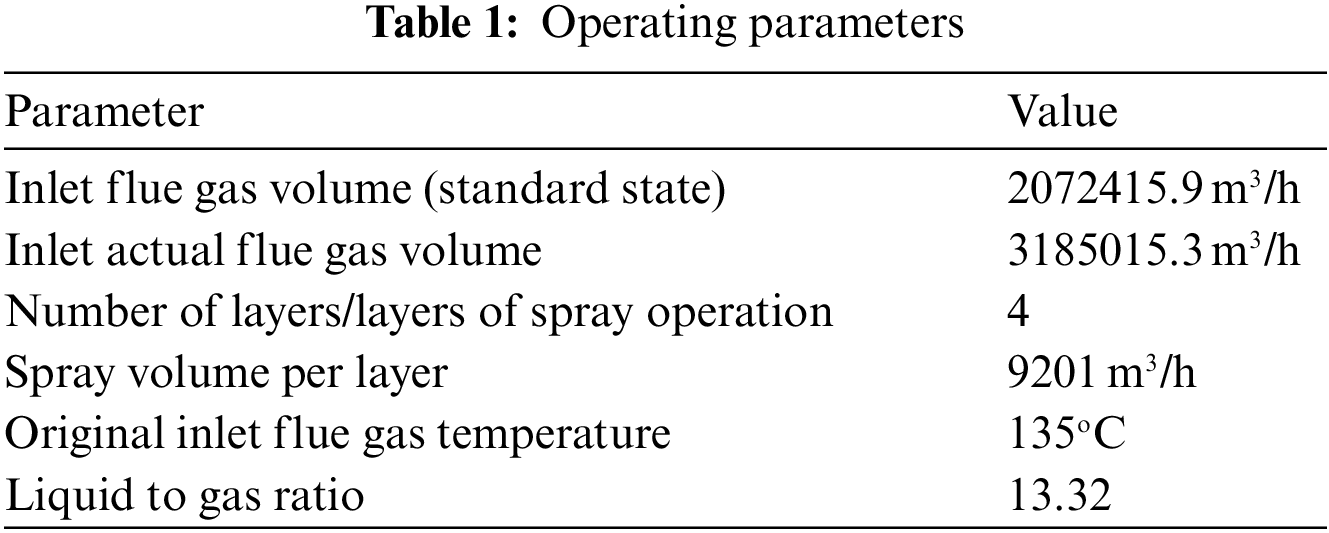
System model (Scheme) A (Fig. 1) proposes a single-stage air temperature control and air preheater coupling scheme. A first-stage gas-gas heat exchanger is installed at the entrance of the desulfurization tower, and the temperature of the flue gas at the entrance of the desulfurization tower is adjusted by using low-temperature air. A part of the heated air is directly passed into the flue of the desulfurization tower outlet, and mixed with the low-temperature clean flue gas at the outlet to produce the exhaust gas temperature of the chimney, effectively increase the elevation of the flue gas, and avoid the phenomenon of white plume. Another part of the heated hot air is passed into the boiler air preheater, and part of the waste heat is recovered to the boiler system to improve boiler efficiency and realize waste heat recovery.
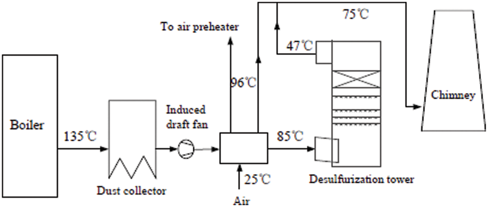
Figure 1: Illustration of system model A
This scheme adopts low-temperature air for heat exchange. Compared with the original GGH net flue gas heat exchange, on the one hand, the heat exchange temperature difference is larger, and the heat exchange efficiency is higher. On the other hand, the leakage of raw flue gas to clean flue gas is avoided, and the emission concentration of clean flue gas is ensured. The other part of the heated air is passed into the boiler air preheater, and the heat recovered from the flue gas is sent to the boiler, which reduces the exhaust gas temperature of the unit, reduces the heat loss of exhaust gas, improves the boiler efficiency, and better realizes the boiler air preheating coupling of heater and flue gas temperature regulation.
Scheme B (Fig. 2) proposes a two-stage series water temperature adjustment and waste heat recovery coupling scheme. A two-stage flue gas heat exchanger is set up in front of the desulfurization tower, and the two-stage flue gas heat exchanger is connected in series with working fluid water, and the working fluid after absorbing heat transfers the heat to the unit’s regenerative system, which can displace part of the steam turbine extraction steam to increase the output of the steam turbine. In addition, in order to avoid the white plume phenomenon caused by the excessively low flue gas temperature at the outlet of the desulfurization tower, part of the heating steam from the thermal power plant is used to heat the flue gas at the tail of the desulfurization system to ensure the elevation of the flue gas.
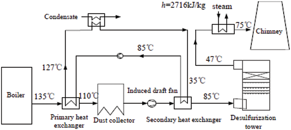
Figure 2: Illustration of system model B
In this scheme, two-stage flue gas heat exchangers are set up. Before the dust collector and the desulfurization tower inlet, respectively, the flue gas temperature at the inlet of the desulfurization tower can be adjusted in stages, and the temperature drop can be distributed reasonably, so as to realize the deep adjustment and ensure the safe operation of the dust collector. After the working water absorbs the heat, all the recovered heat is transferred to the unit’s regenerative system through the surface heat exchanger. Because the flue gas temperature after the desulfurization tower is too low, it is necessary to properly raise the temperature before the flue gas is discharged.
In order to avoid low temperature corrosion of the dust collector, the outlet temperature of the flue gas in the first-stage flue gas heat exchanger must be controlled above the acid dew point. The acid dew point of the flue gas is around 74°C, so the operation of the first-stage flue gas heat exchanger is safe.
Scheme C (Fig. 3) proposes a coupling process of three-stage series flue gas temperature regulation and waste heat recovery. This process uses a three-stage flue gas heat exchanger. The first two-stage heat exchanger is the same as scheme B, but the working water is taken from the condensed water in the regenerative system of the unit, and directly into the regenerative feed water of the unit after the heat exchange is completed. In the system, avoid adverse effects caused by setting heat exchangers. The specific flow direction of the working water is as follows: the working water drawn from the condensate pipe first passes into the secondary heat exchanger, then passes through the primary heat exchanger, absorbs the heat in the flue gas, and continues to pass into the tertiary heat exchanger. The net flue gas at the outlet of the desulfurization tower releases heat and finally returns to the condensate system. This scheme does not need to use other heat sources to heat the net flue gas, which reduces the loss of other heat sources.
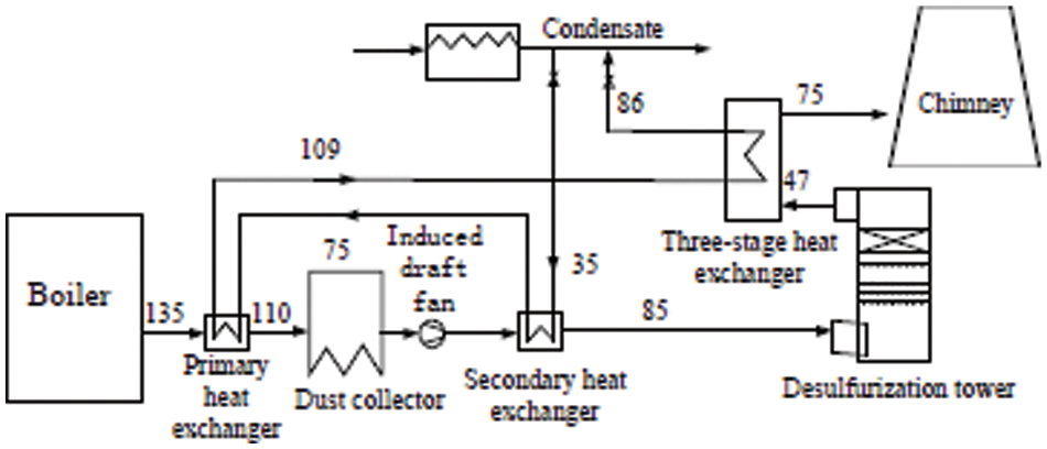
Figure 3: Illustration of system model C
Due to the arrangement of the three-stage flue gas heat exchanger in this scheme, the upper resistance of the flue is larger than that of the two-stage heat exchanger, but the principle of proximity is adopted. Production reduction and other issues. The flue gas temperature is also adjusted in two stages. The medium water after heat exchange is directly fed into the unit’s heat recovery system, and the heat is recovered into the system in a mixed manner, which can reduce the irreversible loss of the system and achieve more efficient waste heat recovery and utilization.
Scheme D (Fig. 4) proposes a scheme for graded adjustment of flue gas temperature at the inlet of the desulfurization tower and graded recovery of waste heat. The three-stage flue gas heat exchanger is also used, and the biggest difference from scheme C is that the working fluid water of the first two-stage flue gas heat exchanger in this scheme is connected in parallel. The working water enters the first and second flue gas heat exchangers respectively, and the working water at the outlet of the first heat exchanger passes into the third heat exchanger to heat up the net flue gas. The working water from the outlet of the secondary heat exchanger is directly returned to the recuperation system of the unit.
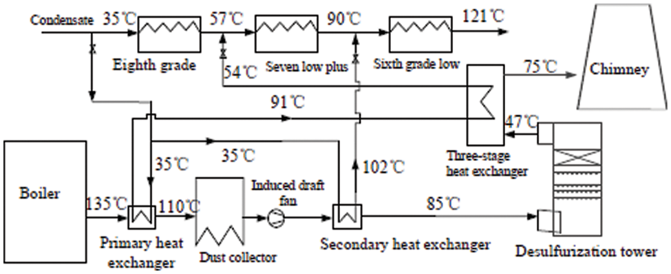
Figure 4: Illustration of system model D
This scheme not only realizes temperature regulation in stages, but also recovers heat in stages. It can effectively reduce the irreversible loss (exergy loss) of the system and maximize the use of waste heat.
4.1 Energy Consumption Characteristics
When calculating the energy consumption of the designed process scheme, the energy consumption changes of the necessary booster fans and the energy consumption changes of newly added energy-consuming equipment are mainly considered.
The energy consumption changes of the four schemes are shown in Figs. 5, and 6 is the heat exchange area required by the heat exchangers arranged in the four schemes, so as to analyze the investment of the schemes. Scheme A reduces the exhaust temperature of the tail flue gas and improves the boiler efficiency of the unit, but the system energy consumption is the largest among the four schemes due to the setting of the air fan and the change of the wind resistance of the flue. In addition, due to the provision of a first-stage gas-air heat exchanger, this type of heat exchanger has a lower heat transfer coefficient than a water-air heat exchanger, so the heat exchange area is the largest. Three-stage heat exchangers are set in the three schemes of B, C, and D. Under the condition that the flue gas temperature adjustment range is the same, the energy consumption increment is not much different.
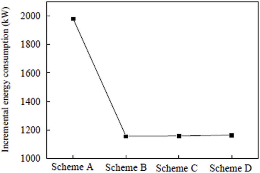
Figure 5: Comparison of energy consumption of the methods
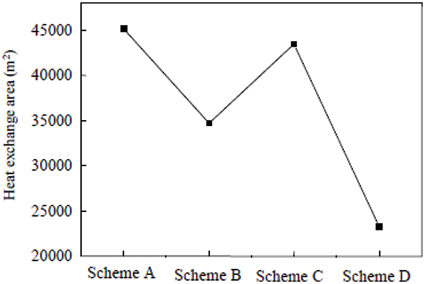
Figure 6: Comparison of heat transfer areas
Scheme D working fluid of the first two heat exchangers is introduced separately, and the temperature drop of the flue gas can be selected flexibly. The adjustment depth of the flue gas temperature of the first and second heat exchangers can be adjusted according to the flow rate of the working fluid and the arrangement of the heat exchanger. Therefore, the total heat exchange area of this scheme is the smallest.
According to the analysis of the energy consumption increment of the system and the heat exchange area, it is comprehensively considered that the scheme D is more conducive to the low energy consumption operation of the system.
4.2 Project Coal Saving Characteristics
In the scheme, the waste heat is recovered into the unit’s regenerative system, and sent to the system as pure heat, which reduces the steam extraction of the steam turbine, and can obtain the increase in the generating power of the unit, and then calculate the coal saving according to the coal consumption of the unit. The regenerative extraction steam parameters of the steam turbine are shown in Table 2, and the corresponding equivalent enthalpy drop parameters obtained by calculation are shown in Table 3.
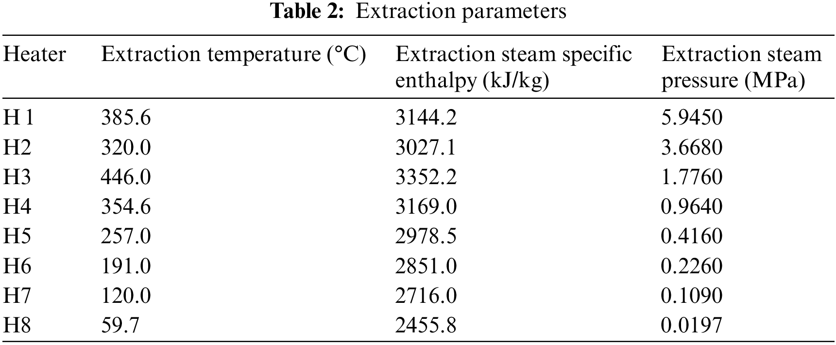
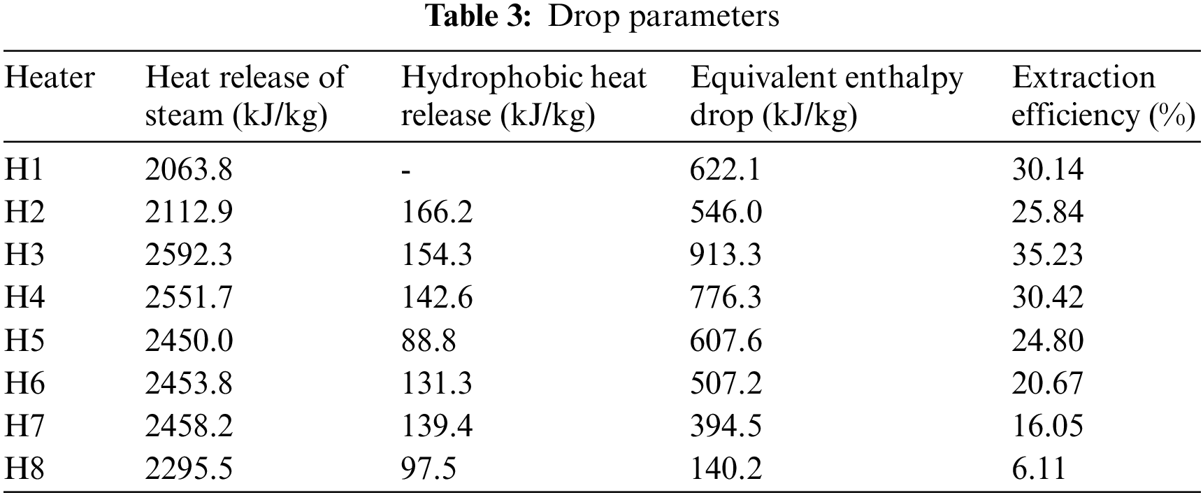
Fig. 7 shows the coal saving characteristics of the four schemes. Combined with the new equipment in the system and the changes in the energy consumption of the original energy-consuming equipment, the coal consumption and coal consumption for power supply of the unit are finally converted to reflect the economy of the scheme.
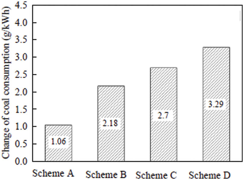
Figure 7: Comparison of coal saving characteristics
Scheme A uses air for waste heat recovery. Due to factors such as heat exchanger efficiency, the recovery capacity is weaker than that of working water, and the amount of waste heat recovery is the lowest. Because of the large amount of induced air, the energy consumption of the system is the highest, so the final coal saving is the least. In scheme B, the waste heat of the flue gas is not used for the heating of the flue gas at the tail, so the amount of waste heat recovery is the largest, but at the same time, steam is used at the tail to heat the flue gas, so this part of the steam does not work in the steam turbine, so the total coal saving is not large. Scheme C uses three-stage heat exchangers in series. Because the tail flue gas needs to be heated, the amount of waste heat recovery is lower than that of scheme B, but the total coal saving is higher than that of scheme B.
For scheme D, the connection method of the heat exchanger is greatly improved. The water at the outlet of the first-stage heater is used to heat the tail flue gas, which does not affect the waste heat recovery of the working fluid of the second-stage heater. The two-stage waste heat recovery is separated and sent to the seventh-stage low-addition and the sixth-stage low-addition in stages. Under the condition of the same flue gas temperature adjustment depth, the economy of the system is maximized. Its final coal saving is the highest among the four schemes.
4.3 Exergy Loss Analysis of Different Waste Heat Recovery Schemes
In the previous waste heat recovery scheme, the heat destination is uneconomical, and the temperature difference at the entry point is large, resulting in large exergy loss, and does not maximize the thermal economy of the system. In view of this situation, according to the first and second laws of thermodynamics, the heat transfer process of the heat exchanger is irreversible, so the heat transfer process must have a reduction in the effective energy of the system, that is, exergy loss. The size of the exergy loss is related to the temperature difference between the heat exchange fluids, and the smaller the temperature difference is, the smaller the exergy loss is. Therefore, the principle of the minimum temperature difference between the media inlet should be followed in waste heat recovery to reduce the effective energy loss of the system. The exergy loss in the heat transfer process of high and low temperature fluids is:
where:
According to the analysis of energy consumption and coal saving, scheme D has the best economy among the four schemes, and the waste heat recovery scheme has variability. According to the analysis, there are four media import methods in this scheme: 1) All imported into the eighth level low plus; 2) The grades are imported into the seventh, and the eighth grades are low-added; 3) The grades are imported into the sixth grade, and the eighth grades are low-added; 4) The grades are imported into the sixth grade, and the seventh grades are added at a low level. The water temperature of the eighth, seventh, and sixth low-add outlet of the unit is 57oC, 90oC, and 121oC respectively.
Fig. 8 shows the economics and exergy analysis of the four import methods. The results show that the temperature difference between the fluids is the smallest in the six-level and seventh-level low-add confluence methods. The increase in power generation is 5.76 MW, and the coal consumption for power supply is reduced by 3.29 g/(kW⋅h). Calculate the ratio of exergy loss to waste heat recovery as the exergy loss percentage, and the exergy loss percentage of the obtained scheme. It is 1.05%, and the loss of usable energy is the smallest. This way of importing is the most economical, and maximizes the recovery of waste heat to the unit’s heat recovery system.
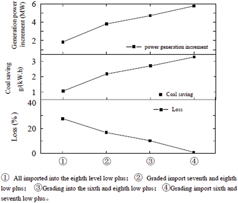
Figure 8: Comparison of the economic parameters of the proposed methods
In order to realize the coupling of flue gas temperature regulation and waste heat recovery, under the high desulfurization efficiency, four feasible process schemes are proposed, respectively. Use cold air and working water to adjust the flue gas temperature, and use the waste heat to adjust the flue gas temperature. It is recycled to the boiler air preheater and the unit regenerative system. The economics of the four process schemes, the following conclusions are obtained:
1) Due to working medium and heat exchanger efficiency, among other things, the overall waste heat recovery capacity is limited when utilizing air for flue gas tempering and waste heat recovery, and the investment and energy consumption are the highest.
2) Combined with the heat recovery system, when the condensed water is used as the heat exchange working medium, the total waste heat recovery capacity is high, and the system investment and energy consumption are relatively low. The use of steam to heat the tail flue gas will significantly reduce the thermal economy of the system, so it should be considered to use the recovered heat to heat the tail flue gas. The four schemes reduce the standard coal consumption of power supply by 1.06, 2.18, 1.91, and 3.29 g/(kW⋅h) respectively.
3) Using the condensed water of the unit as the working fluid, and grading the waste heat into the regenerative system of the unit can maximize the utilization of the waste heat of the flue gas. When recovering the waste heat of flue gas, the principle of minimum temperature difference at the entry point should be followed to reduce the effective energy loss of the system and maximize the thermal economy of the system. The application of the optimal solution proposed in this paper can reduce the coal consumption of the 660 MW unit by 3.29 g/(kW⋅h).
The future research will consider the economic analysis of the desulfurization system and evaluate the propose idea.
Acknowledgement: The authors would like to thanks the editors and reviewers for their review and recommendations.
Funding Statement: The authors received no specific funding for this study.
Conflicts of Interest: The authors declare that they have no conflicts of interest to report regarding the present study.
References
1. Y. Guo, C. Zheng, J. Shu, H. Dong, Y. Zhang et al., “Modeling and optimization of wet flue gas desulfurization system based on a hybrid modeling method,” Journal of the Air & Waste Management Association, vol. 69, no. 5, pp. 565–575, 2018. [Google Scholar]
2. X. R. Zhang, X. Chen, W. Sun and X. Z. He, “Vehicle re-identification model based on optimized DenseNet121 with joint loss,” Computers, Materials & Continua, vol. 67, no. 3, pp. 3933–3948, 2021. [Google Scholar]
3. X. R. Zhang, H. L. Wu, W. Sun, A. G. Song and S. K. ha, “A fast and accurate vascular tissue simulation model based on point primitive method,” Intelligent Automation & Soft Computing, vol. 27, no. 3, pp. 873–889, 2021. [Google Scholar]
4. Y. Chen, Y. Kang, Y. Zhao, L. Wang, J. Liu et al., “A review of lithium-ion battery safety concerns: The issues, strategies, and testing standards,” Journal of Energy Chemistry, vol. 59, no. 2, pp. 83–99, 2021. [Google Scholar]
5. H. Wu, Y. Ciou, J. Wu and D. Huang, “Study of natural convection of lithium-ion battery module employing phase change material,” Processes, vol. 9, no. 11, pp. 1–17, 2021. [Google Scholar]
6. T. Buidin and F. Mariasiu, “Modeling approach of an air-based battery thermal management system for an electric vehicle,” Applied Sciences, vol. 11, no. 15, pp. 1–17, 2021. [Google Scholar]
7. X. Wang, S. Liu, Y. Zhang, S. Lv, H. Ni et al., “A review of the power battery thermal management system with different cooling, heating and coupling system,” Energies, vol. 15, no. 6, pp. 1–15, 2022. [Google Scholar]
8. W. Cao, C. Zhao and Y. Wang, “Thermal modeling of full-size-scale cylindrical battery pack cooled by channeled liquid flow,” International Journal of Heat and Mass Transfer, vol. 138, no. 3, pp. 1178–1187, 2019. [Google Scholar]
9. R. Yang, R. Xiong, W. Shen and X. Lin, “Extreme learning machine-based thermal model for lithium-ion batteries of electric vehicles under external short circuit,” Engineering Journal, vol. 7, no. 3, pp. 345–405, 2021. [Google Scholar]
10. M. Astaneh, J. Andric, L. Lofdahl and P. Stopp, “Multiphysics simulation optimization framework for lithium-ion battery pack design for electric vehicle applications,” Energy Journal, vol. 239, no. 2, pp. 1292–1304, 2022. [Google Scholar]
11. G. Xia, L. Cao and G. Bi, “A review on battery thermal management in electric application,” Journal of Power Sources, vol. 367, no. 3, pp. 90–105, 2017. [Google Scholar]
12. A. Sarchami, M. Najafi, A. Iman and E. Houshfar, “Experimental study of thermal management system for cylindrical li-ion battery pack based on nanofluid cooling and copper sheath,” International Journal of Thermal Sciences, vol. 171, no. 7, pp. 1072–1085, 2022. [Google Scholar]
13. L. Fan, J. Khodadadi and A. Massage, “A parametric study on thermal management of an air-cooled lithium-ion battery module for plug-on hybrid electric vehicles,” Journal of Power Sources, vol. 238, no. 3, pp. 301–312, 2013. [Google Scholar]
14. Z. Li, J. Cen and P. Peng, “Experimental research on thermal management of cylindrical lithium-ion batteries,” New Energy Development, vol. 4, no. 4, pp. 305–311, 2016. [Google Scholar]
15. T. Wang, K. Zhu, J. Zhao and C. Shen, “Thermal investigation of lithium-ion battery module with different cell arrangement structures and forced air-cooling strategies,” Applied Energy, vol. 134, no. 7, pp. 229–238, 2014. [Google Scholar]
16. N. Yang, X. Zhang and G. Li, “Assessment of the forced air-cooling performance for cylindrical lithium-ion battery packs: A comparative analysis between aligned and staggered cell arrangements,” Applied Thermal Engineering, vol. 80, no. 6, pp. 55–65, 2015. [Google Scholar]
17. Y. Wang, Q. Gao, P. Lu, M. Zhao and W. Bao, “A review on research status and key technologies of battery thermal management and its enhanced safety,” International Journal of Energy Research, vol. 42, no. 13, pp. 4008–4033, 2018. [Google Scholar]
18. X. Zhang, X. Kong and G. Li, “Thermodynamic assessment of active cooling/heating methods for lithium-ion batteries of electric vehicles in extreme conditions,” Energy Journal, vol. 64, no. 3, pp. 1092–1101, 2014. [Google Scholar]
19. J. Tsai, S. Chen, S. Chen and H. Chiang, “Air pollutant emission abatement of the fossil-fuel power plants by multiple control strategies in Taiwan,” Energies, vol. 14, no. 18, pp. 1–18, 2021. [Google Scholar]
20. X. Liu, H. Yang and J. Lyu, “Optimization of fluidization state of a circulating fluidized bed boiler for economical operation,” Energies, vol. 13, no. 2, pp. 1–18, 2019. [Google Scholar]
21. Z. Zhao, Y. Zhang, W. Gao, J. Baleta, C. Liu et al., “Simulation of SO2 absorption and performance enhancement of wet flue gas desulfurization system,” Process Safety and Environmental Protection, vol. 150, no. 3, pp. 453–463, 2021. [Google Scholar]
22. O. Khaleel, T. Ibrahim, F. Ismail, A. Sammarraire and S. Hassan, “Modeling and analysis of optimal performance of a coal-fired power plant based on exergy evaluation,” Energy Reports, vol. 8, no. 4, pp. 2179–2199, 2022. [Google Scholar]
23. Y. Jiang, H. Zhang, R. Zhao, Y. Wang, M. Liu et al., “Energy, exergy, economic and environmental assessment of the triangular solar collector assisted heat pump,” Solar Energy, vol. 236, no. 4, pp. 280–293, 2022. [Google Scholar]
24. J. Wang, W. Liu, G. Liu, W. Sun, G. Li et al., “Theoretical design and analysis of the waste heat recovery system of turbine exhaust steam using an absorption heat pump for heating supply,” Energies, vol. 13, no. 23, pp. 1–19, 2020. [Google Scholar]
25. J. Liu, X. Gong, W. Zhang, F. Sun and Q. Wang, “Experimental study on a flue gas waste heat cascade recovery system under variable working conditions,” Energies, vol. 13, no. 2, pp. 1–22, 2022. [Google Scholar]
26. G. Zhou, Z. Fan, H. Zhang, X. Dong, J. Wang et al., “Ventilation cooling design for a novel 350-MW air-cooled turbo generator,” IEEE Access, vol. 6, pp. 62184–62192, 2018. [Google Scholar]
27. J. Lim, H. Cho and J. Kim, “Optimization of wet flue gas desulfurization system using recycled waste oyster shell as high-grade limestone substitutes,” Journal of Cleaner Production, vol. 318, no. 5, pp. 1282–1305, 2021. [Google Scholar]
28. E. Adah, A. Joubert, R. Boudhan, M. Henry, S. Durecu et al., “Spray scrubber for nanoparticle removal from incineration fumes from the incineration of waste containing nanomaterials: Theoretical and experimental investigations,” Aerosol Science and Technology, vol. 56, no. 1, pp. 75–91, 2022. [Google Scholar]
29. S. Chi, T. Luan, Y. Liang, X. Hu and Y. Cao, “Analysis and evaluation of multi-energy cascade utilization system for ultra-supercritical units,” Energies, vol. 13, no. 15, pp. 1–17, 2020. [Google Scholar]
30. M. Ahmadi, M. Nazari, M. Sadeghzadeh, F. Pourfayaz, M. Ghazvini et al., “Thermodynamic and economic analysis of performance evaluation of all the thermal power plants: A review,” Energy Science & Engineering, vol. 7, no. 1, pp. 30–65, 2019. [Google Scholar]
31. S. Shamsi, A. Negash, G. Cho and Y. Kim, “Waster heat and water recovery system optimization for flue gas in thermal power plants,” Sustainability, vol. 11, no. 7, pp. 1–19, 2019. [Google Scholar]
32. Y. Fu, Y. Zhao, M. Liu, J. Wang and J. Yan, “Optimization of cold-end system of thermal power plants based on entropy generation minimization,” Frontiers in Energy, vol. 4, no. 3, pp. 883–895, 2021. [Google Scholar]
33. T. Darbandi, M. Risberg and L. Westerlund, “Efficient cleaning and heat recovery of flue gas from a small-scale boiler,” Chemical Engineering & Technology, vol. 44, no. 11, pp. 2116–2125, 2021. [Google Scholar]
34. K. Witkowski, P. Haering, S. Seidelt and N. Pini, “Role of thermal technologies for enhancing flexibility in multi-energy systems through sector coupling: Technical suitability and expected developments,” IET Energy Systems Integration, vol. 2, no. 2, pp. 69–79, 2020. [Google Scholar]
35. G. Gohar, M. Khan and H. Raza, “Recovery and effective utilization of waste heat from the exhaust of internal combustion engines for cooling applications using ANSYS,” Journal of Mechanical Engineering Science, vol. 236, no. 9, pp. 5022–5032, 2021. [Google Scholar]
36. Y. Xiao, Y. Xia, A. Jiang, X. Lv, Y. Lin et al., “Research on optimization of coal slime fluidized bed boiler desulfurization cooperative operation,” Processes, vol. 9, no. 1, pp. 1–18, 2021. [Google Scholar]
37. Z. Lei, H. Zhou, W. Hu, G. Liu, S. Guan et al., “Toward a web-based digital twin thermal power plant,” IEEE Transactions on Industrial Informatics, vol. 18, no. 3, pp. 1716–1725, 2021. [Google Scholar]
38. W. Xu, Y. Jin, L. Zhu and Z. Li, “Performance analysis of the technology of high-temperature boiler feed water to recover the waste heat of mid-low-temperature flue gas,” ACS Omega, vol. 6, no. 40, pp. 26318–26328, 2021. [Google Scholar]
39. P. Larrinaga, A. Celador, J. Legarreta and G. Diarce, “Evaluation of the theoretical, technical and economic potential of industrial waste heat recovery in the basque country,” Journal of Cleaner Production, vol. 312, no. 5, pp. 1298–1309, 2021. [Google Scholar]
40. H. Zhang, Y. Dong, Y. Lai, H. Zhang and X. Zhang, “Waste heat recovery from coal-fired boiler flue gas: Performance optimization of a new open absorption heat pump,” Applied Thermal Engineering, vol. 183, no. 1, pp. 1611–1623, 2021. [Google Scholar]
41. D. Teng, L. An, G. Shen, S. Zhang and H. Zhang, “Experimental study on a ceramic membrane condenser with air medium for water and waste heat recovery from flue gas,” Membranes, vol. 11, no. 9, pp. 1–18, 2021. [Google Scholar]
Cite This Article
 Copyright © 2023 The Author(s). Published by Tech Science Press.
This work is licensed under a Creative Commons Attribution 4.0 International License , which permits unrestricted use, distribution, and reproduction in any medium, provided the original work is properly cited.
 Downloads
 Citation Tools