
 Submit a Paper
 Propose a Special lssue
 Open Access
ARTICLE

An Improved Calibration Method of Grating Projection Measurement System
College of Computer Science and Technology, Changchun Normal University, 130000, Changchun, China
* Corresponding Author: Qiucheng Sun. Email:
Computers, Materials & Continua 2023, 75(2), 3957-3970. https://doi.org/10.32604/cmc.2023.037254
Received 28 October 2022; Accepted 09 February 2023; Issue published 31 March 2023
 View Full Text
 Download PDF
Abstract
In the traditional fringe projection profilometry system, the projector and the camera light center are both spatially virtual points. The spatial position relationships specified in the model are not easy to obtain, leading to inaccurate system parameters and affecting measurement accuracy. This paper proposes a method for solving the system parameters of the fringe projection profilometry system, and the spatial position of the camera and projector can be adjusted in accordance with the obtained calibration parameters. The steps are as follows: First, in accordance with the conversion relationship of the coordinate system in the calibration process, the calculation formula of the vertical distance from the camera light center to the reference plane and the calculation formula of the distance between the projector and the camera light center are given respectively. Secondly, according to the projector calibration principle, the position of the projector light axis perpendicular to the reference plane is gained by comparing the parallel relationship between the reference plane coordinate system and the projector coordinate system’s Z-axis. Then, in order to fulfill the position restriction that the line between the projector light center and the camera light center must be parallel to the reference plane, the camera’s spatial location is adjusted so that the vertical distance between it and the reference plane tends to that between the projector light center and the reference plane. And finally, the three-dimensional (3D) reconstruction of the target object can be finished using the phase height model’s system parameters once the aforementioned position limitations are put into practice. Experimental results demonstrate that the method improves the measurement accuracy, and verifies that it is effective and available in 3D shape measurement.Keywords
Phase measuring profilometry (PMP) [1] is a famous active optical measurement method, which plays an important role in measuring 3D surface shape and object deformation due to its characteristics of high precision, non-destructive, full-field and non-contact. With the emergence of low-cost experimental components, PMP has been widely applied in biomedical industry, industrial inspection, machine vision, profile modeling, reverse engineering, etc. [2–6].
A projector and a camera make up the traditional phase measuring profilometry system. The process is that the projector projects a group of grating with certain phase and periodic changes to the tested object. The camera captures the image of the modulated deformation grating fringes, and the phase information of the grating fringes can be obtained through image processing. Then the pixel coordinates of each point on the surface of the object are obtained by decoding. The surface contour or warping of the object can be recreated from the photos using phase-height mapping. Although PMP measurement system has been widely used, there are some uncertainties in practical application and measurement, which may lead to errors in shape construction. The main problem is the difficulty in determining the precise location relationship between the projector and the camera when building a traditional PMP system.
In order to overcome this problem, numerous researchers have made efforts in recent years. Some early the literature [7,8] guaranteed the strict position constraints of the traditional PMP system and are committed to solving the accurate system parameters. Zhou et al. [9] proposed a direct phase height mapping algorithm that obtains a linear mapping of the phase plane height and phase difference through multiple measurements of the phase of various target planes, and the light axis of the projector does not have to be orthogonal to the reference plane. Tavares et al. [10] proposed a single-plane linear calibration method to explain the correlation between height and phase. But the practical operation is not limited to the proposed linear relationship. However, some researchers believe that the position constraints of the traditional PMP system are not easily met and have improved the position structure of the camera and projector in the traditional PMP system, such as adding the deflection angle into the traditional phase height model, which has relaxed the vertical and parallel conditions. Mao et al. [11] presented a improve optical structure that only requires the optical element to be moved in order for the two light axes to intersect in the reference plane, which improved the operability of the experiment. Xiao et al. [12] proposed an improved method whereby the positional constraints of the projector and camera are relaxed and only the two light axes are required to meet at the one point of the plane, which improves the operability and simplicity of the experiment. However, coordinate transformation must be taken into account. Bian et al. [13] also realized the limitations of the traditional model and suggested a new model. The maneuverability of the experiment is enhanced by the addition of rotation angles when the two pupil heights of the projection and imaging system are not equal and the corresponding axes are not collinear. With continuous investigation, many scholars have diligently to change the measurement system’s structure and have subsequently created the relevant phase-height mapping method [14]. Du et al. [15] proposed a phase-to-height model using 12 coefficients. However, the model complexity of this method is relatively high, it is not widely used. Zhang et al. [16] discussed the internal relationship between two height models in PMP method, i.e., geometric transformation and matrix transformation, and deduced the phase height model with nine coefficients by using structural constants, which further simplifies the model parameters. Ma et al. [17] suggested a new phase-height model that relaxed the rigid position restrictions for the projector and the camera and simplified the experiment. Kang et al. [18] proposed a phase height model using nine coefficients. But each object requires at least two measurements of different heights to uniquely determine the coefficient, which increasing the complexity of the calculation.
However, the introduction of these parameters increases the complexity of the model. Due to the simplicity of the traditional model calculation, the model still has a certain practical significance. This paper proposes a method for solving the system parameters of the fringe projection profilometry (FPP) system. This method manually adjusts the projector’s and camera’s spatial positions in accordance with the calibration parameters, making the calculated system parameters conform to the positional constraints of the model. This solves the issue of low measurement accuracy caused by inaccurate system parameters in the past and ensures the accuracy of the model.
The structure of the essay is as follows. Section 2 describes the four-step phase shift method’s basic idea. Section 3 introduces the equation derivation of the traditional phase height model. In Section 4, the method for determining the distance between the optical center of the camera and the projector’s light center as well as the distance between the optical center of the camera and the reference plane is presented. Section 5 provides an experimental comparison of the method with conventional measurement methods. Finally, the conclusions of this paper are presented in Section 6.
The technique is to project a set of fringe images onto the object, and use the CCD camera to capture the modulated grating fringe images. The grating light intensity distribution function obtained after the modulation of the CCD camera is as follows, of which the projected stripe pattern satisfies the standard sinusoidal distribution.
In which
Since accurate relative phase values can be obtained by using few experimental images, the four-step phase-shift approach is applied in this paper [19].
The phase main value equation can be obtained by using Eq. (2).
Since the arctangent function is used in Eq. (3), the phase principal value obtained from the four-step phase-shift method is wrapped in the interval of
Fig. 1 shows the Phase-unwrapping. First, it shows the pictures of the phase shift grating acquired at three different frequencies (140/134/129). Secondly, the phase wrapping operation is carried out using the phase shift approach, and the phase-unwrapping operation is carried out using the heterodyne principle, finally the 3D measurement is completed in the 3D software according to the 3D data of the measured object.
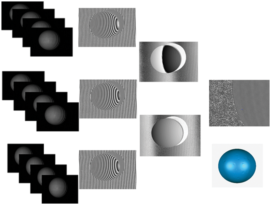
Figure 1: Phase-unwrapping diagram
3 Phase-to-Height Mapping Algorithm
A camera plus a projector make up an FPP system. The principle of the FPP system is triangulation measurement model.
Fig. 2 shows the geometric mathematical model of grating projection system,
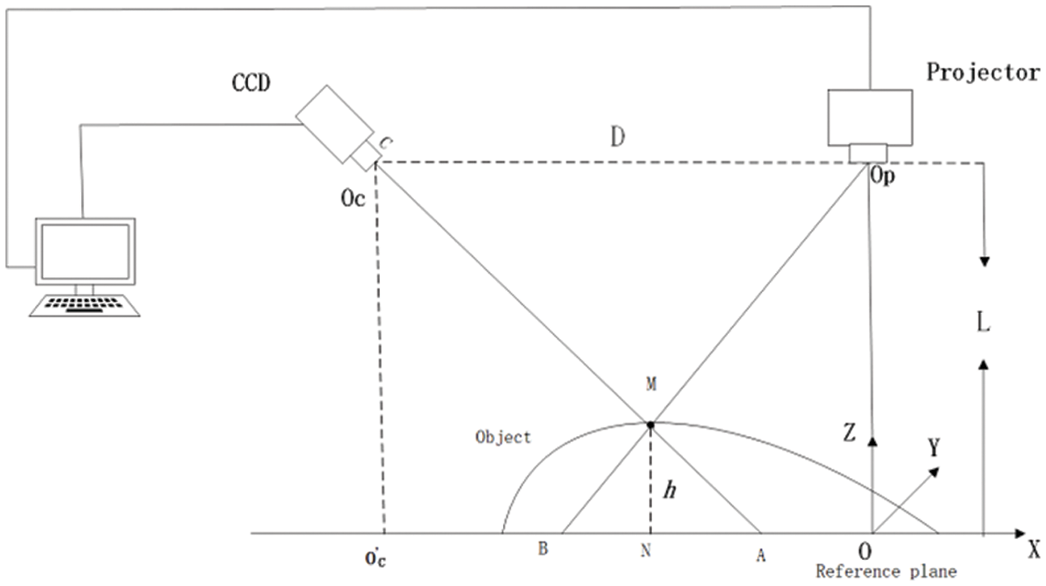
Figure 2: Traditional PMP system
In
In
Hence,
Hence,
In Eq. (10),
Eq. (11) is the height-phase mapping relation of the traditional fringe projection measurement system. In Eq. (11),
4 Solving the Parameters
This section gives the solution process of the vertical distance
The principle diagram of coordinate system transformation in the process of camera calibration is shown in the Fig. 3. The imaging process is a series of transformations of spatial object points in the four coordinate systems shown in Fig. 3.
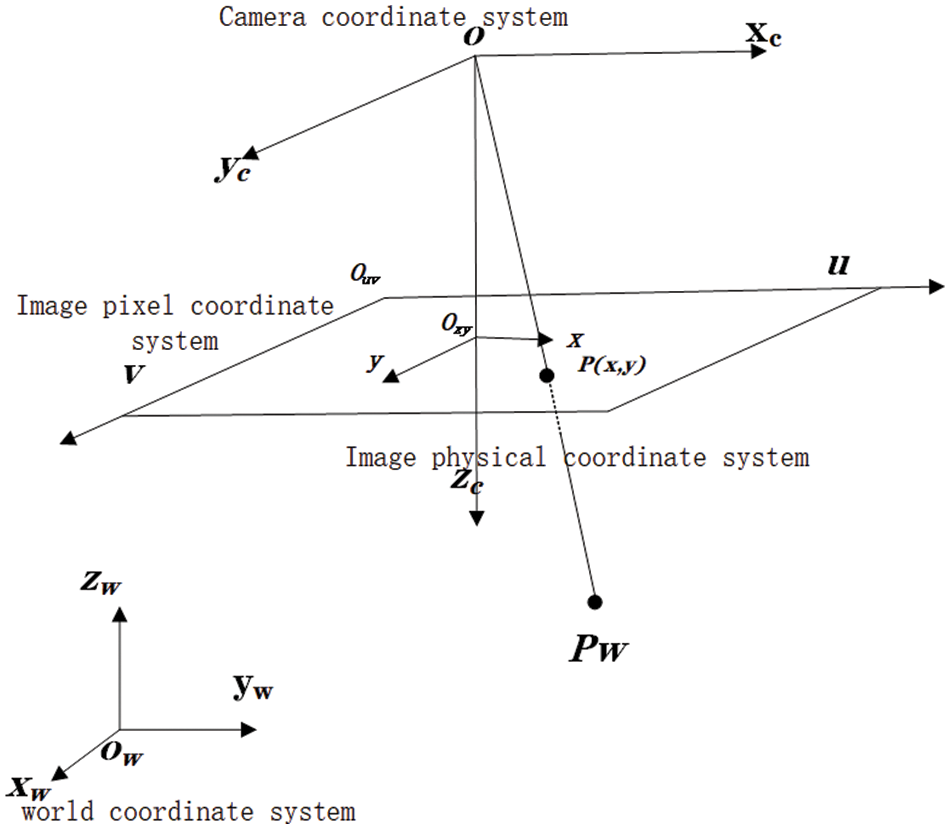
Figure 3: Coordinate transformation diagram of the model of the camera
The spatial attitude of the target plane can be transformed arbitrarily in the calibration process. When the target plane is confined within the reference plane, the target plane is the reference plane. Then
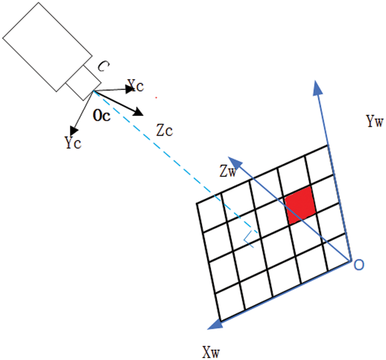
Figure 4: Conversion relationships between the world and the camera coordinate systems
In the calibration process, the vertical distance
When
4.2 Solving for the Parameter
In the binocular camera model [25], the spatial position association of the left and right cameras is related as follows, where
In the measurement model, the projector is often seen as another camera. Thus, the spatial position of the projector and the CCD camera can also be represented by
In this paper, Falcao’s projector camera calibration method [26] is adopted to obtain the external parameters of the projector, the principle is as follows:
• Camera parameters obtained by Zhang’s calibration method.
• Compute the calibration plane under the camera coordinate system.
• Detect the corners of the projected checkerboard.
• Recover the 3D spatial coordinates of the projected board through the ray plane intersection points.
• Correspondence between passed 2D and 3D points calibrated projector.
The model diagram of the camera and projector is shown in Fig. 5. The main steps of projector calibration experiment are as follows:
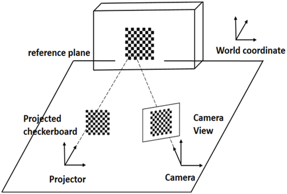
Figure 5: Camera and projector model diagram
Step 1: Capture of the experimental photograph, where the calibration plate and the projector checkerboard must be in the same plane, as shown in Fig. 6.
Step 2: Calculate the internal and external parameters of the CCD camera.
Step 3: Calculate the internal and external parameters of the projector.
Step 4: Calculate the relative position of the projector to the camera.
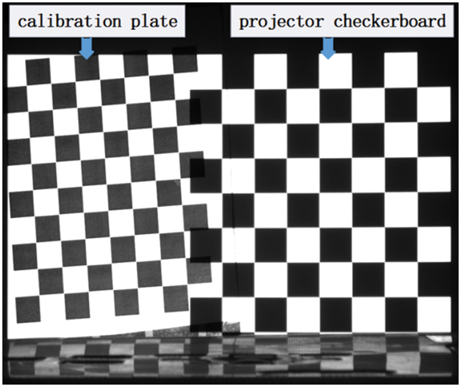
Figure 6: Camera-projector Calibration
The external parameter
An experimental system is created, as illustrated in Fig. 5, in order to validate the method suggested in this study. The experiment uses a DLP4500 projector with a resolution of
Preparation: Prepare to build the experimental system, including the test object and reference plane, projection and imaging system.
Calibration: Conduct monocular camera calibration and camera-projector calibration experiments, and adjusts the spatial positions of the projector and camera in accordance with the calibration data, making the calculated system parameters L and D conform to the positional constraints of the model.
Phase shift method: Projection stripes to the object, the camera collects the image of the distorted raster stripes, and the phase wrapping operation is carried out using the phase shift approach, and the phase-unwrapping operation is carried out using the heterodyne principle
Data processing: The 3D measurement is completed in the 3D software according to the 3D data of the measured object.
The location constraints of the projector and the camera are satisfied by experimental operation debugging, the process is as follows:
In the preparation stage of the experiment, the light center line of the projector and camera is ensured to be parallel to the target plane as much as possible, and the light axis of the projector is also orthogonal to the reference plane as much as possible. It is difficult to guarantee the initial spatial pose accuracy, the relative positions of the reference plane, projector and camera are further calibrated by the coming operations.
Firstly, the parameters of the projector and the camera are obtained from monocular camera calibration and camera-projector calibration, then the expressions of the z-axis of the projector coordinate system and the z-axis of the world coordinate system are calculated from the calibration data. It is thought that the projector light axis is perpendicular to the reference plane in the system when the z-axis of the projector coordinate system is parallel to the z-axis of the world coordinate system (adjust the projector attitude to find the optimal solution), as are shown in Fig. 7a. Next, the vertical distance
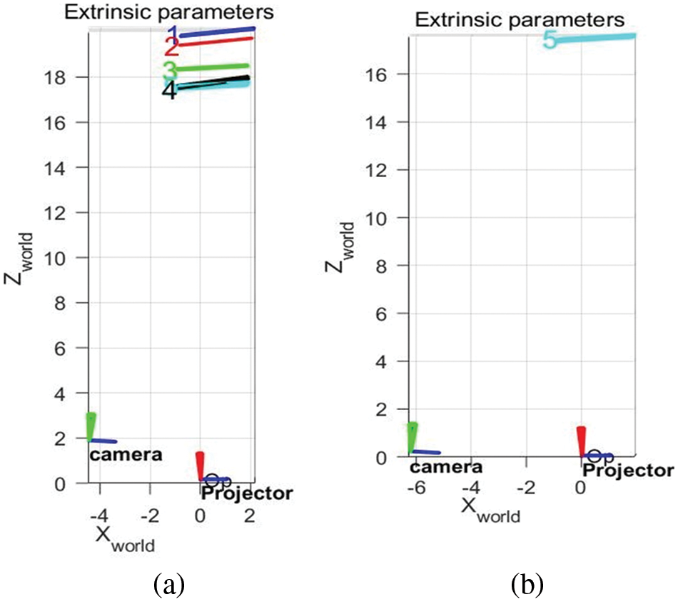
Figure 7: Calibration process of experimental system
After completing the above operation, fix the projector and reference plane positions. The vertical distance L from the camera light center to the reference plane can be measured by the monocular camera calibration experiment. Manually adjust the position of the camera so that the value of L tends to L1. When the absolute value of the difference between
The experiments are divided into face model morphology reconstruction and rectangular hexahedron accuracy measurement with known height. In order to verify that the method has a good reconstruction effect on complex surfaces, a 3D rebuilding of the face model is first implemented.
Fig. 8 is the images of the intensity of the deformation stripes on the target object collected by the CCD camera.
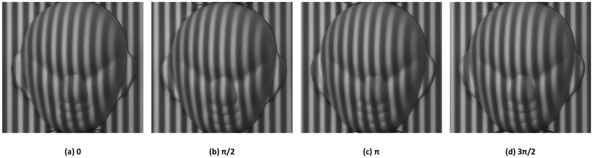
Figure 8: Experimental photo of Four-step phase shift method
Fig. 9 shows the real image, the point cloud image and the 3D model map of the face model.
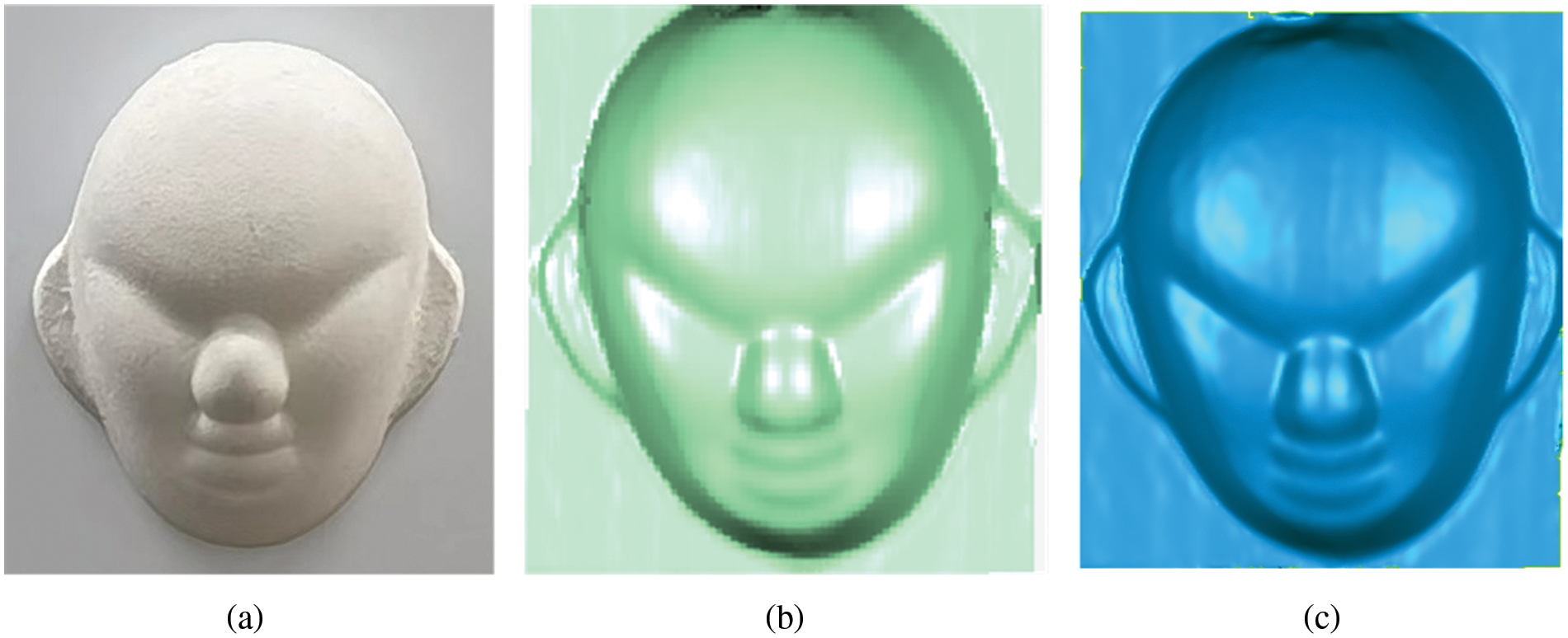
Figure 9: (a) Image of the face model, (b) The point cloud image of the face model, and (C) a truthful view of the face model
To further verify the accuracy of this method, a series of rectangular hexahedra with known height were measured by the proposed method. The distance between the two planes is calculated to obtain the average height of the rectangular hexahedron. Using this method, the 5, 12, and 20 mm rectangular hexahedra are measured repeatedly. For comparison, the results of the measurements using traditional measurement method and X. bian’ s measurement method (adding the rotation angle and relaxing the position restriction of the model) are also given.
Fig. 10 shows the real image and the point cloud image of the rectangular hexahedron. According to point cloud data, the upper and lower planes of the rectangular hexahedron are fitted, as shown in Fig. 11.
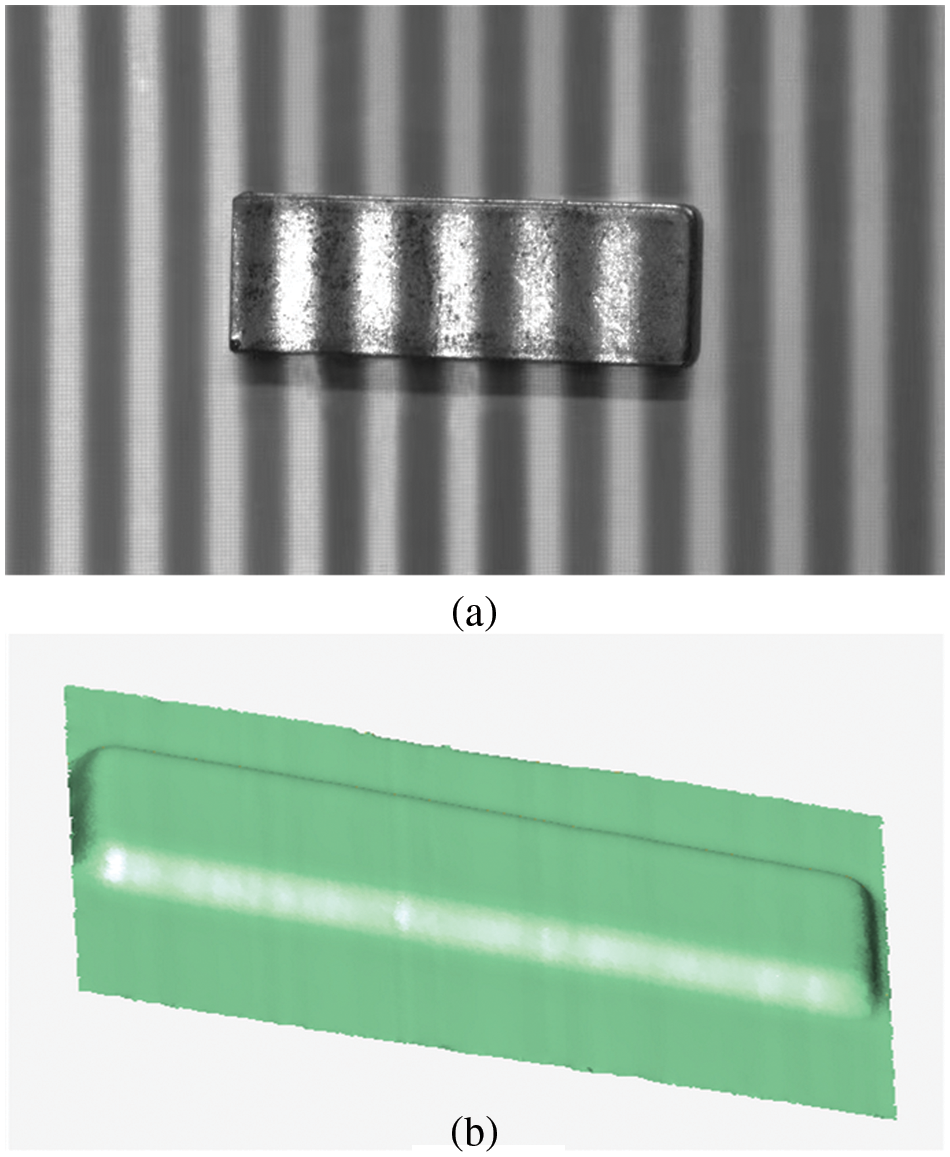
Figure 10: (a) Image of the Rectangular hexahedron with prominent stripes, (b) The point cloud image of the Rectangular hexahedron
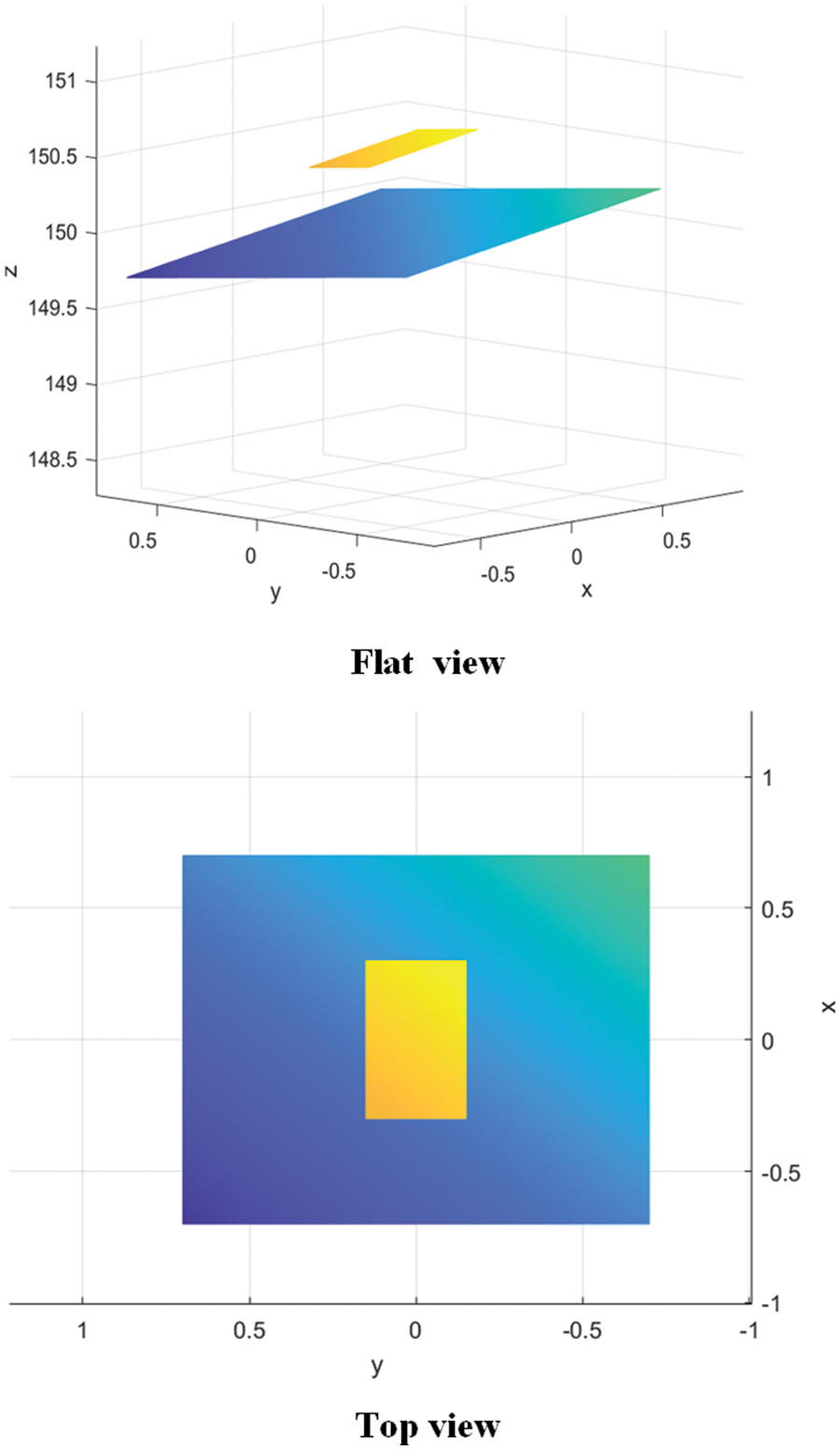
Figure 11: The upper and lower plans of rectangular hexahedron
In Tables 1 and 2,
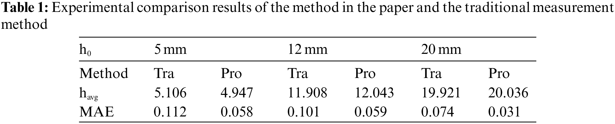
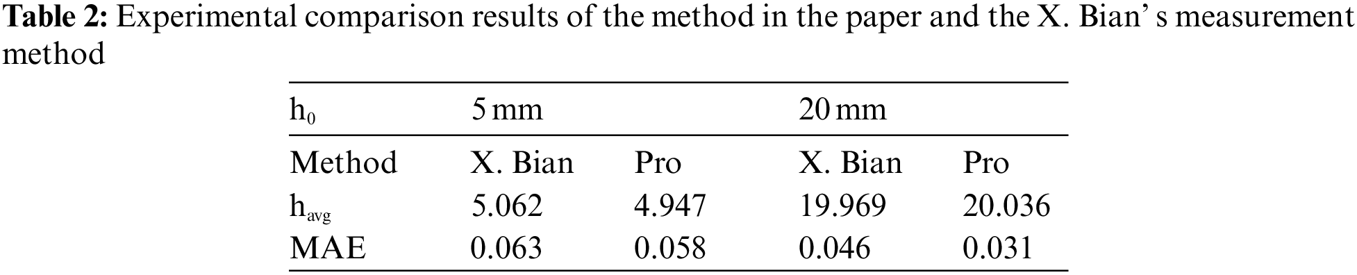
The above experiments show that the method has good 3D reconstruction results and improves the measurement accuracy.
In this paper, a calibration method is proposed to calculate the distance from projector light center to the camera light center and the distance from projector light center to the reference plane according to the external parameters of camera-projector and camera calibration process. During the experiment, the technique modifies the projector’s and camera’s relative positions, and improves the calculation accuracy of the system parameters L and D. The experimental results show that the method is effective and available. In addition, the method has higher accuracy and operability compared to the traditional measurement method.
Acknowledgement: The authors acknowledge the support of teacher Weiming Li from Guilin University of Electronic Science and Technology.
Funding Statement: This work described in this paper is supported by Foundation of Jilin Province Department of Science and Technology under Grant YDZJ202201ZYTS531.
Conflicts of Interest: The authors declare that they have no conflicts of interest to report regarding the present study.
References
1. S. Gorthi and P. Rastogi, “Fringe projection techniques: Whither we are?” Optics and Lasers in Engineering, vol. 48, no. 2, pp. 133–140, 2010. [Google Scholar]
2. D. Liu, X. Qu, J. Dong, P. Zhou, Y. Cheng et al., “Context-aware biaffine localizing network for temporal sentence grounding,” in IEEE/CVF Conf. on Computer Vision and Pattern Recognition (CVPR), Nashville, TN, USA, pp. 11230–11239, 2021. [Google Scholar]
3. J. A. M. Rodríguez, “Micro-scale spherical and cylindrical surface modeling via metaheuristic algorithms and micro laser line projection,” Algorithms, vol. 15, no. 5, pp. 145, 2022. [Google Scholar]
4. J. Niu, Y. Fu, Q. Hu, S. Yang, T. Zhang et al., “A 3d measurement method based on coded image,” Computers, Materials & Continua, vol. 69, no. 2, pp. 1839–1849, 2021. [Google Scholar]
5. M. Thakur, C. J. Tay and C. Quan, “Surface profiling of a transparent object by use of phase-shifting talbot interferometry,” Applied Optics, vol. 44, no. 13, pp. 2541–5, 2005. [Google Scholar] [PubMed]
6. S. Zhang, “Recent progresses on real-time 3d shape measurement using digital fringe projection techniques,” Optics and Lasers in Engineering, vol. 48, no. 2, pp. 149–158, 2010. [Google Scholar]
7. Z. Zhang, P. Li, S. Zhao, Z. Lv, F. Du et al., “An adaptive vision navigation algorithm in agricultural IoT system for smart agricultural robots,” Computers, Materials & Continua, vol. 66, no. 1, pp. 1043–1056, 2021. [Google Scholar]
8. J. Zhang, K. Yu, Z. Wen, X. Qi and A. K. Paul, “3D reconstruction for motion blurred images using deep learning-based intelligent systems,” Computers, Materials & Continua, vol. 66, no. 2, pp. 2087–2104, 2021. [Google Scholar]
9. W. S. Zhou and X. Y. Su, “A direct mapping algorithm for phase-measuring profilometry,” Optica Acta International Journal of Optics, vol. 41, no. 1, pp. 89–94, 1994. [Google Scholar]
10. P. J. Tavares and M. A. Vaz, “Linear calibration procedure for the phase-to-height relationship in phase measurement profilometry,” Optics Communications, vol. 274, no. 2, pp. 307–314, 2007. [Google Scholar]
11. X. Mao, W. Chen and X. Su, “Improved Fourier-transform profilometry,” Applied Optics, vol. 46, no. 5, pp. 664–668, 2007. [Google Scholar] [PubMed]
12. Y. Xiao, Y. Cao and Y. Wu, “Improved algorithm for phase-to-height mapping in phase measuring profilometry,” Applied Optics, vol. 51, no. 8, pp. 1149, 2012. [Google Scholar] [PubMed]
13. X. Bian, F. Zuo and J. Cheng, “Analysis of a new phase and height algorithm in phase measurement profilometry,” Optical Review, vol. 25, no. 2, pp. 190–196, 2018. [Google Scholar]
14. L. Huang, P. S. Chua and A. Asundi, “Least-squares calibration method for fringe projection profilometry considering camera lens distortion,” Applied Optics, vol. 49, no. 9, pp. 1539, 2010. [Google Scholar] [PubMed]
15. H. Du and Z. Wang, “Three-dimensional shape measurement with an arbitrarily arranged fringe projection profilometry system,” Optics Letters, vol. 32, no. 16, pp. 2438–40, 2007. [Google Scholar] [PubMed]
16. X. Zhang, C. Li, Q. Zhang and D. Tu, “Rethinking phase height model of fringe projection profilometry: A geometry transformation viewpoint,” Optics & Laser Technology, vol. 108, pp. 69–80, 2018. [Google Scholar]
17. Q. Ma, Y. Cao, C. Chen, Y. Wan, G. Fu et al., “Intrinsic feature revelation of phase-to-height mapping in phase measuring profilometry,” Optics & Laser Technology, vol. 108, pp. 46–52, 2018. [Google Scholar]
18. J. -C. Kang, C. -S. Kim, I. -J. Pak, J. -R. Son and C. -S. Kim, “A new phase to height model in fringe projection profilometry by considering radial distortion of camera lens,” Optik, vol. 247, pp. 167895, 2021. [Google Scholar]
19. D. Liu, X. Qu, J. Dong and P. Zhou, “Reasoning step-by-step: Temporal sentence localization in videos via deep rectification-modulation network,” in Proc. of the 28th Int. Conf. on Computational Linguistics, Barcelona, Spain, pp. 1841–1851, 2020. [Google Scholar]
20. C. Yu and Q. Peng, “A Correlation-based phase unwrapping method for Fourier-transform profilometry,” Optics & Lasers in Engineering, vol. 45, no. 6, pp. 730–736, 2007. [Google Scholar]
21. D. Liu, X. Qu, X. -Y. Liu, J. Dong, P. Zhou et al., “Jointly cross-and self-modal graph attention network for query-based moment localization,” in Proc. of the 28th ACM Int. Conf. on Multimedia, New York, NY, USA, pp. 4070–4078, 2020. [Google Scholar]
22. W. Zhu, X. Li and Y. Shon, “Research on clothing simulation design based on three-dimensional image analysis,” Computers, Materials & Continua, vol. 65, no. 1, pp. 945–962, 2020. [Google Scholar]
23. Z. Zhang, “A flexible New technique for camera calibration,” IEEE Transactions on Pattern Analysis and Machine Intelligence, vol. 22, no. 11, pp. 1330–1334, 2000. [Google Scholar]
24. Jean-Yves Bouguet, “Camera calibration toolbox for matlab ®,” [Online]. Available: http://www.vision.caltech.edu/bouguetj/calib_doc/ [Google Scholar]
25. J. Hu, F. Zhang, Z. Li and H. Huang, “Research on indoor three dimensional measurement algorithm based on binocular technology,” Computer Measurement and Control, vol. 27, no. 9, pp. 66–70, 2019. [Google Scholar]
26. G. Falcao, N. Hurtos and J. Massich, “Plane-based calibration of a projector-camera system,” vibot master, 2008. [Online]. Available: https://procamcalib.googlecode.com/files/ProCam_Calib_v2.pdf [Google Scholar]
Cite This Article
 Copyright © 2023 The Author(s). Published by Tech Science Press.
This work is licensed under a Creative Commons Attribution 4.0 International License , which permits unrestricted use, distribution, and reproduction in any medium, provided the original work is properly cited.
 Downloads
 Citation Tools