
 Submit a Paper
 Propose a Special lssue
 Open Access
ARTICLE

Efficient Technique for Image Cryptography Using Sudoku Keys
1 Department of ECE, Karunya Institute of Technology and Sciences, Coimbatore, 641114, India
2 Faculty of Computer and Artificial Intelligence, Beni-Suef University, Beni-Suef, 62511, Egypt
3 Nuclear Engineering and Fluid Mechanics Department, University of the Basque Country, Bilbao, 48940, Spain
4 Department of Mathematics, Faculty of Education, Kafkas University, Kars, 36100, Turkey
* Corresponding Author: Hatıra Günerhan. Email:
Computers, Materials & Continua 2023, 77(1), 1325-1353. https://doi.org/10.32604/cmc.2023.035856
Received 07 September 2022; Accepted 27 February 2023; Issue published 31 October 2023
 View Full Text
 Download PDF
Abstract
This paper proposes a cryptographic technique on images based on the Sudoku solution. Sudoku is a number puzzle, which needs applying defined protocols and filling the empty boxes with numbers. Given a small size of numbers as input, solving the sudoku puzzle yields an expanded big size of numbers, which can be used as a key for the Encryption/Decryption of images. In this way, the given small size of numbers can be stored as the prime key, which means the key is compact. A prime key clue in the sudoku puzzle always leads to only one solution, which means the key is always stable. This feature is the background for the paper, where the Sudoku puzzle output can be innovatively introduced in image cryptography. Sudoku solution is expanded to any size image using a sequence of expansion techniques that involve filling of the number matrix, Linear X-Y rotational shifting, and reverse shifting based on a standard zig-zag pattern. The crypto key for an image dictates the details of positions, where the image pixels have to be shuffled. Shuffling is made at two levels, namely pixel and sub-pixel (RGB) levels for an image, with the latter having more effective Encryption. The brought-out technique falls under the Image scrambling method with partial diffusion. Performance metrics are impressive and are given by a Histogram deviation of 0.997, a Correlation coefficient of 10−2 and an NPCR of 99.98%. Hence, it is evident that the image cryptography with the sudoku kept in place is more efficient against Plaintext and Differential attacks.Keywords
In the modern world, technological advancement makes our daily lives very convenient, so global access to information is very much possible. The Multimedia domain has paved the way for online transactions and processing. On the other hand, the threat imposed on information security is big. Hence, improving information security and overcoming information leakage are critical tasks for technology users. As far as information carrying ability is concerned, the image data is superior to the text since the images have the advantage of holding large volumes of information via efficient techniques Traditional encryption algorithms such as Data Encryption standards and Rivest-Shamir-Adleman algorithms offer solutions in text cryptography. However, such solutions have partially met the criteria of data security and time objectives through respective cryptography techniques. Hence image cryptography has become more effective and popular in the research field [1]. Chaos-based Image encryption is a research field. With the rise of Metaverse, the Encryption of 3D models is more focused. One of the approaches is the 3DME-SC method, where 2D chaotic systems using a logistic map, infinite collapse (2D-LAIC), and semi-tensor product (STP) theory are used. Although chaos is complex, the 3DME-SC exhibits good performance and effectiveness [2]. In the field of watermarking, Fractional-order continuous orthogonal moments (FrCOMs) is a recent research topic, limited to planar images. One of the approaches extends the application to stereoscopic images by combination with Trinion theory [3].
Image encryption is categorized into two methods, namely Scrambling and Diffusion, based on encryption strategy. The pixel locations are interchanged or shuffled in the former technique. Hence, the correlation between neighboring pixels will be eliminated and result in efficient Encryption. The pixel values are subjected to changes in the Diffusion technique so that the property of the original image is broken and the pixel correlation is lost. By transposition, the encrypted image has less chance of data loss during decryption. By value transformation, the reconstruction of images may suffer significant variation from the actual image [4]. These factors are considered during the encryption algorithm selection process.
The purpose of this work is to attempt cryptography on images of any size using a number matrix defined by a well-known sudoku protocol. The primary hypothesis considered for this work is that Sudoku can encrypt and decrypt images without compromising the encryption robustness. The number matrix in a solved sudoku puzzle forms the base for the key construction. The property of this matrix is that numbers do not get duplicated within the defined pattern. This scheme is a simple solution for generating the shuffled number matrix that defines the pixel position for encryption. Rotational shifting of the cells and reverse shifting techniques across a full matrix add ruggedness to the crypto key.
The challenges imposed on the crypto key for such encryption are compact keys, easily processable, the robustness of encrypted products over plaintext and differential attacks on data, etc. The key must also be capable of encrypting images of any size. With these factors as mandatory constraints, Sudoku is used in cryptography in this work. Sudoku must be interpreted as a controlled non-repetitive random number sequence, which can be predicted from the intermediate numbers. When the complexity of the number puzzle increases, the volume of the intermediate numbers decreases. Encryption has been tried using various entities like DNA, fingerprint patterns, etc. Sudoku can also be visualized as a suitable crypto key for image encryption.
A Literature survey is conducted to explore the image encryption techniques and sudoku concepts. Image encryption techniques have drastically improved to maintain image confidentiality from data security threats. Image encryption techniques are compared to assess the encryption efficiency, and choose the best suitable cryptography technique. The trade-off between the Encryption complexity i and the computation time is the critical factor for choosing the suitable encryption technique. Fast processing technique, the encryption complexity may not satisfy the required encryption ruggedness. Pixel permutation assists in guarding the multimedia data. Many algorithms emerge to improve speed and data protection [4].
An algorithm by the name of Rijndael was applied, along with image shuffling. The image is grouped under small sections of 4 × 4 pixels, and their location is shuffled, followed by restructuring so that a wholly shuffled image is obtained. Data pre-shuffling before implementing the Rijndael algorithm ensures that the encrypted image becomes alien compared with the original image. When the shuffling pattern is inversely applied along with the Rijndael decryption, the actual image is obtained. These techniques must perfectly suit the Cryptography requirements in a private environment [5,6].
An affine transform is used to cross-locate the image pixels, followed by exclusive OR-ing. The result is an efficient, simple encrypted image. The 64-bit key is used in this technique. The first 32 bits (4 × 8-bit key) are used for the location transformation via the affine transformation, and the second 32 bits (4 × 8-bit key) are used for exclusive OR-ing on every 2 × 2 clusters of pixels. Thus the output image becomes completely decorrelated from the actual image [7].
Another method involves Scrambling, where the original image is broken based on bit-planes. Resultant images are shuffled using a suitable encryption technique. Shuffled images are used to reconstruct the image based on bit-planes, and hence the encrypted image is obtained. This technique exhibits good encryption efficiency when compared with conventional scrambling techniques, due to the introduction of bit-plane-based image decomposition [8].
A contemporary technique is proposed, where the RGB sub-pixel values are shuffled for the given image without disturbing the sub-pixel values. For an image of size m × n, this shuffling retains the image sub-pixels as such but with each pixel’s components distributed to random locations resulting in a completely different output image. The adjacent pixel correlation between pixels, as well as sub-pixels, gets broken. Any two sub-pixel shifts are not alike, and the shuffling pattern is also different between every sub-pixel matrix as a whole [9].
The Sudoku gains attention in the signal processing domain as it is analogous to the error-correcting codes in terms of a discrete characteristic problem. The techniques used to resolve such error-correcting codes are applied to sudoku with suitable transformation. This analogy indicates that solutions for sudoku are alternatively applied to error-correcting codes and provide a different approach to solution estimation. The similar nature is possible due to the perspective approach and the possible representations of a problem. Such new perspectives are compared with Sudoku for innovative solutions [10]. Recent research has been done [11–18].
Sudoku is a puzzle in which different symbols (usually digits 1 through maximum) are arranged in an array such that the arrangement agrees with given clues and meets the puzzle constraints [19]. Sudoku is a discrete characteristic problem that must be seen beyond a simple number puzzle. Sudoku is short for “Su-ji wa dokushin ni kagiru” that is translated as “the numbers must be single”. 6,670,903,752,021,072,936,960 different sudoku puzzles and equivalent solutions can be made for a 9 × 9 Sudoku [20]. If the Sudoku solution is used for Image encryption, there are plenty of provisions to choose one of these as a key for encryption.
Sudoku is bound by the rule that Every row, column and Block of cells has every value only once. These characteristics ensure that an N-element sudoku solution can generate an N ∗ N number sequence. A proper sudoku is a single solution matrix, which means that for a given sudoku clue, there exists one and only one solution. For image encryption, this is a mandatory requirement to avoid ambiguity in deriving the crypto key. The complexity of Sudoku is determined by many patterned terminologies like Single candidate, X-wing, forcing chain, swordfish, etc. [21,22]. These terminologies refer to the clue pattern. These concepts need to be taken into consideration for key compacting. Key compacting is not discussed in this paper; instead, the focus is more on the Encryption technique.
Two block diagrams correspond to key generation and encryption schemes (Refer to Figs. 1 and 2). Key generation from a sudoku solution matrix is the first block flow, while the encryption concept is the second block flow. Sudoku solution (n × n size) has to be converted to a proper crypto key (M × N size) which involves Expansion, Sequencing and Shuffling. The result of the process is a crypto key to the required image size.
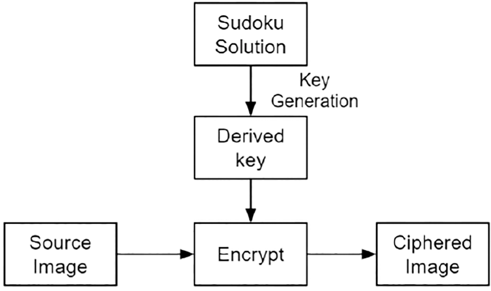
Figure 1: Block diagram-image ciphering

Figure 2: Block diagram-crypto key generation
Based on the cipher key, Encryption is performed by pixel position transformation on the RGB layer of subpixels. Thus, the robustness is increased, and a better-ciphered image is obtained. encrypted output is assessed by histogram analysis, correlation coefficient analysis and differential measure analysis [23]. Implementation is done in Python software using Google Colaboratory with runtime file access for I/O operations [24].
The Input key needs to be validated to yield the correct crypto key. The method involves validation of the number matrix to ensure all are non-zero, relevant, and non-repeating. The Length and Count mismatches in all Rows and Columns are checked. Following are the steps to be followed in input key validation.
• The order of the matrix = n. The row count and column count of the read text are cross-checked with the order value of the matrix to validate the size of the sudoku solution key.
• Each element of the read matrix is checked for 0 < Key(i, j) < n + 1. When the values of elements exceed this limit, then the key is considered invalid.
• The matrix key is checked for the sudoku characteristics All elements in each row and column are different. All rows have different elements in every column.
The input number matrix is first validated for a proper sudoku solution. Enhancements come into the picture for three criteria. The first criterion is that the column count in the final image must be a multiple of the column count in the sudoku solution. Once this criterion is not met, the matrix column count is revised to the roof multiple of the sudoku column count. After calculations, such columns are isolated and removed.
The Second criterion is that the length of the sequencing pattern must match the row count of the image matrix while sequencing. In case this criterion is not met, errors occur in the sequencing. When there is a mismatch due to a more extended sequencing pattern, proportional numbers of the sequence are not allocated to the number matrix, resulting in a discontinuous number sequence. When there is a mismatch due to a shorter sequencing pattern, proportional matrix numbers do not participate in the sequence, resulting in a number sequence with multiple duplicates. Mismatch is eliminated by expanding or truncating techniques.
Third criterion is that the length of the rotational shift pattern must match the column count of the image matrix during the downward shifts. The length of the rotational shift pattern must match the row count of the image matrix during the rightward shifts. Mismatches result in unshifted rows or columns. Hence few sections of the number matrix remain unshuffled, yielding a poor crypto key. The generation of the effective crypto-key lies in how these mismatches are correctly handled, meeting the criteria. The process criterion highlights the significance of the Image size in the crypto key generation. Hence, three Cases are separately brought out:
• Case 1 refers to the square size image, where the row count equals the column count in the Image matrix. The number of rows or columns are direct multiplication factors of the input key rows or columns.
• Case 2 refers to the wide rectangle size image, where the row count exceeds the column count in the Image matrix.
• Case 3 refers to the long rectangle size image, where the column count exceeds the row count in the image matrix.
In Cases 2 & 3, the row or column count may/may not be direct multiples of the Input key rows or columns. Crypto key generation involves three steps in sequence, namely Expansion, Sequencing and Shuffling. The study of this method can be replicated by parallel execution of activities in the same sequence described in the respective sections. The flowchart of this encryption algorithm explains all the processes involved in this algorithm (Refer to Figs. 3a and 3b).
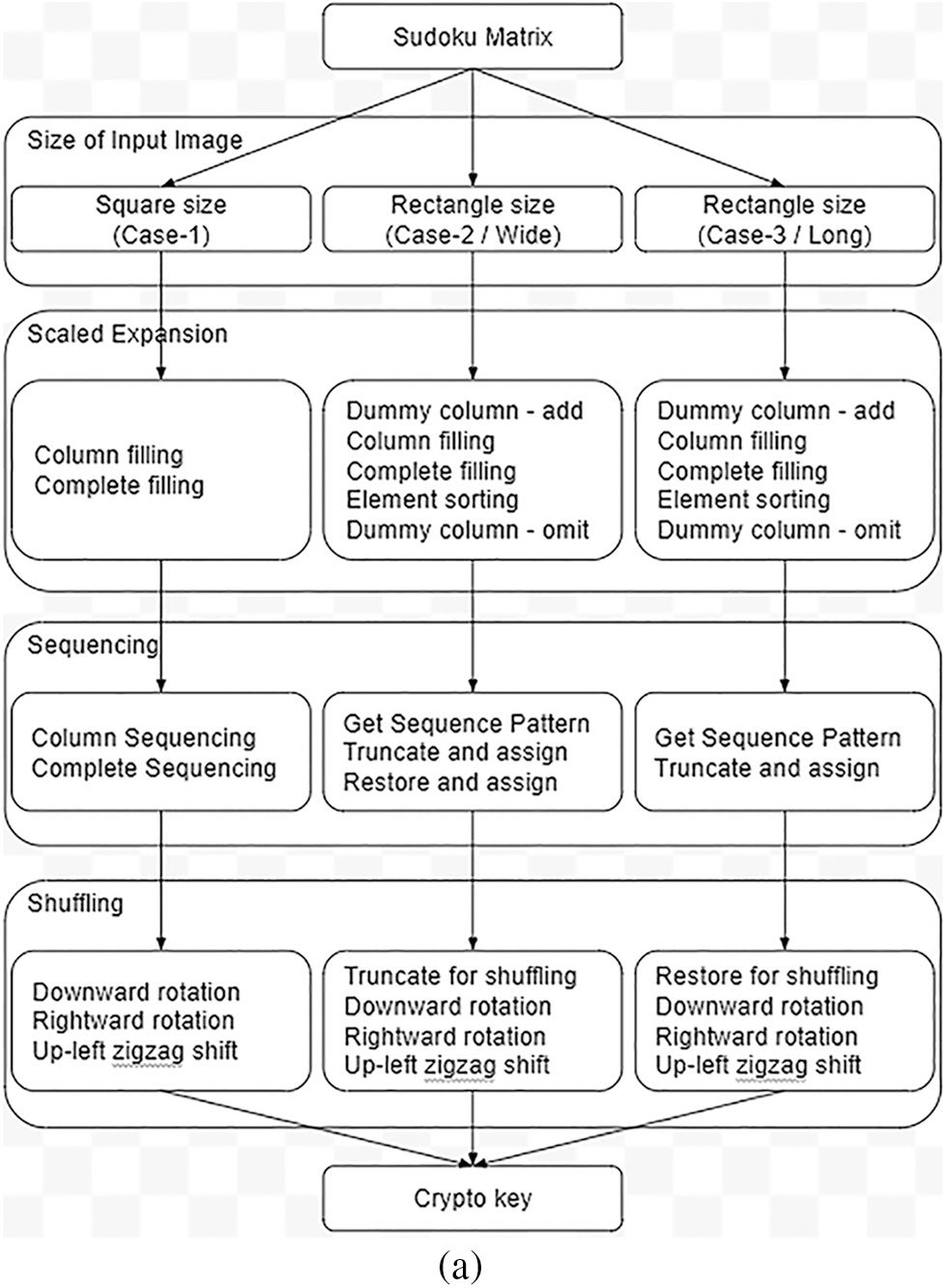
Figure 3a: Flowchart-crypto key generation
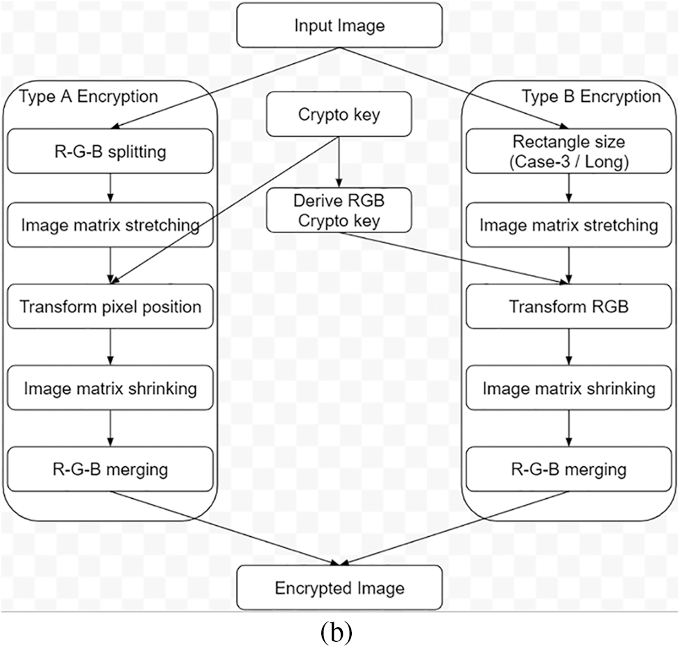
Figure 3b: Flowchart-image encryption
5 Crypto Key Generation–Case 1
• The image size (N × N) is a multiple of the key’s size (n × n). Hence the key’s row and column need not be truncated or expanded by any offsets (Refer to Fig. 4). Scaled Expansion of the key is required to match the image size.
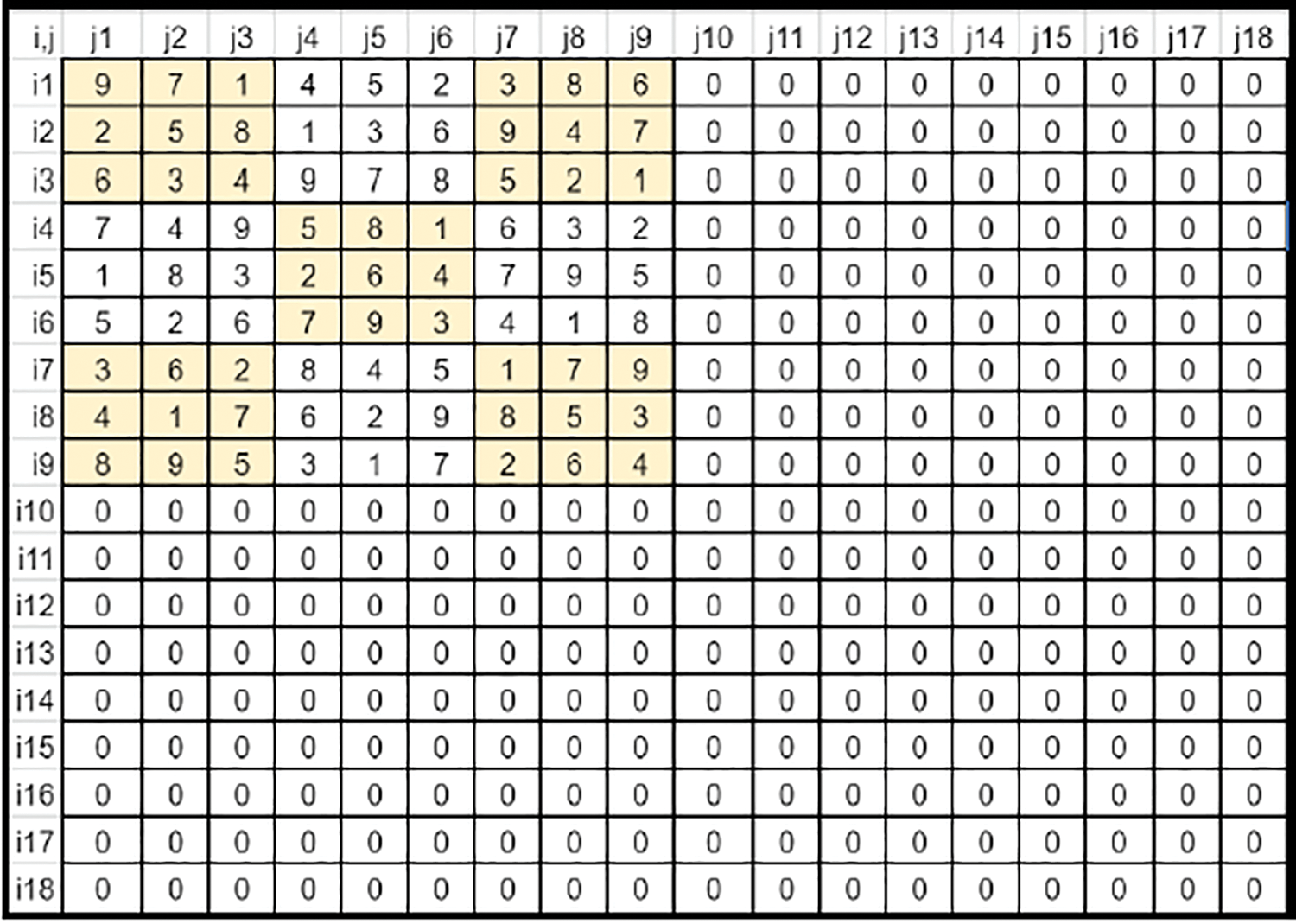
Figure 4: Sudoku matrix (Case 1) fit into key's matrix
• The count the key needs to be scaled is stored as ‘ifactor’ along the Vertical axis (Top to down) and as ‘jfactor’ along the Horizontal axis (Left to right).
• Key is expanded along the Horizontal axis in each row by filling right rotated (single shift) values of the previous set of values. This method fills all elements of the base key rows. (Refer to Fig. 5).
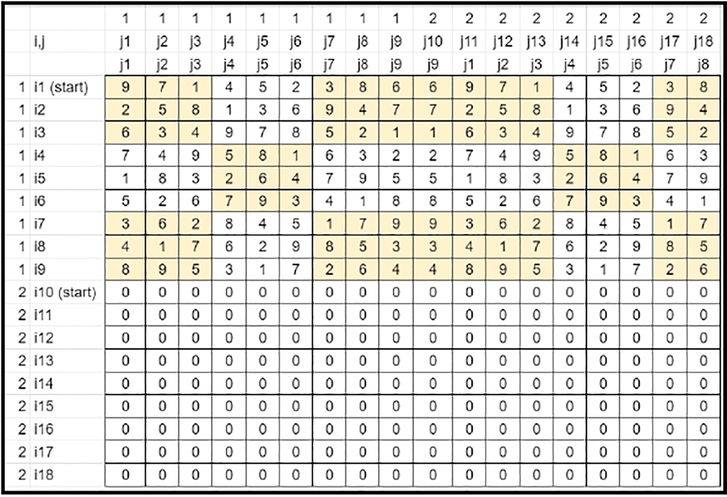
Figure 5: Key’s matrix-column filling
• The key is expanded along the vertical axis in each column by filling down rotated (single shift) values of the previous set of values. This method fills all elements of the matrix (Refer to Fig. 6).
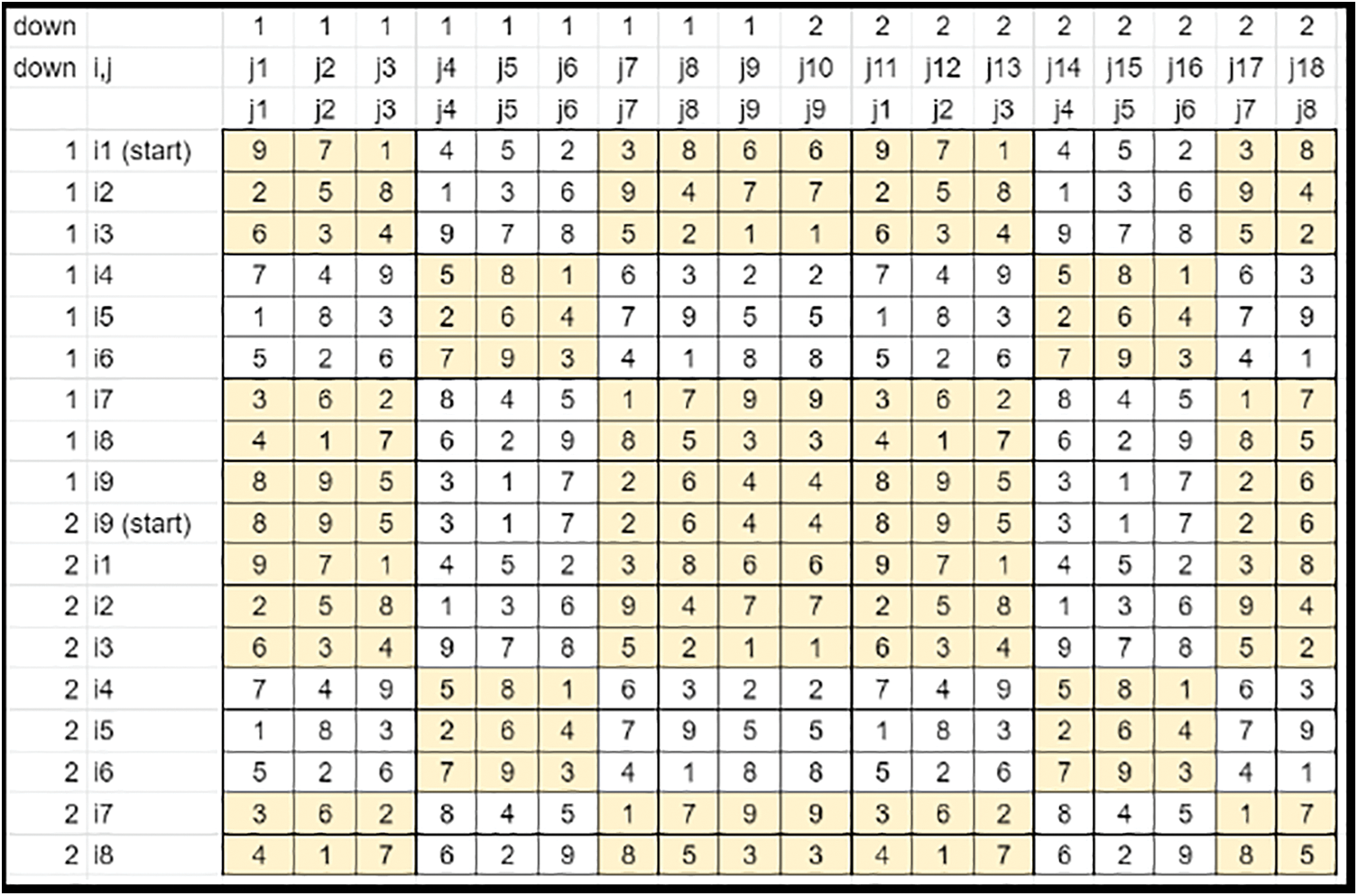
Figure 6: Key matrix-complete filling
• In all the rows, the elements are scaled by the corresponding ‘jfactor’ values so that all row elements range from 1 to N (Refer to Fig. 7).
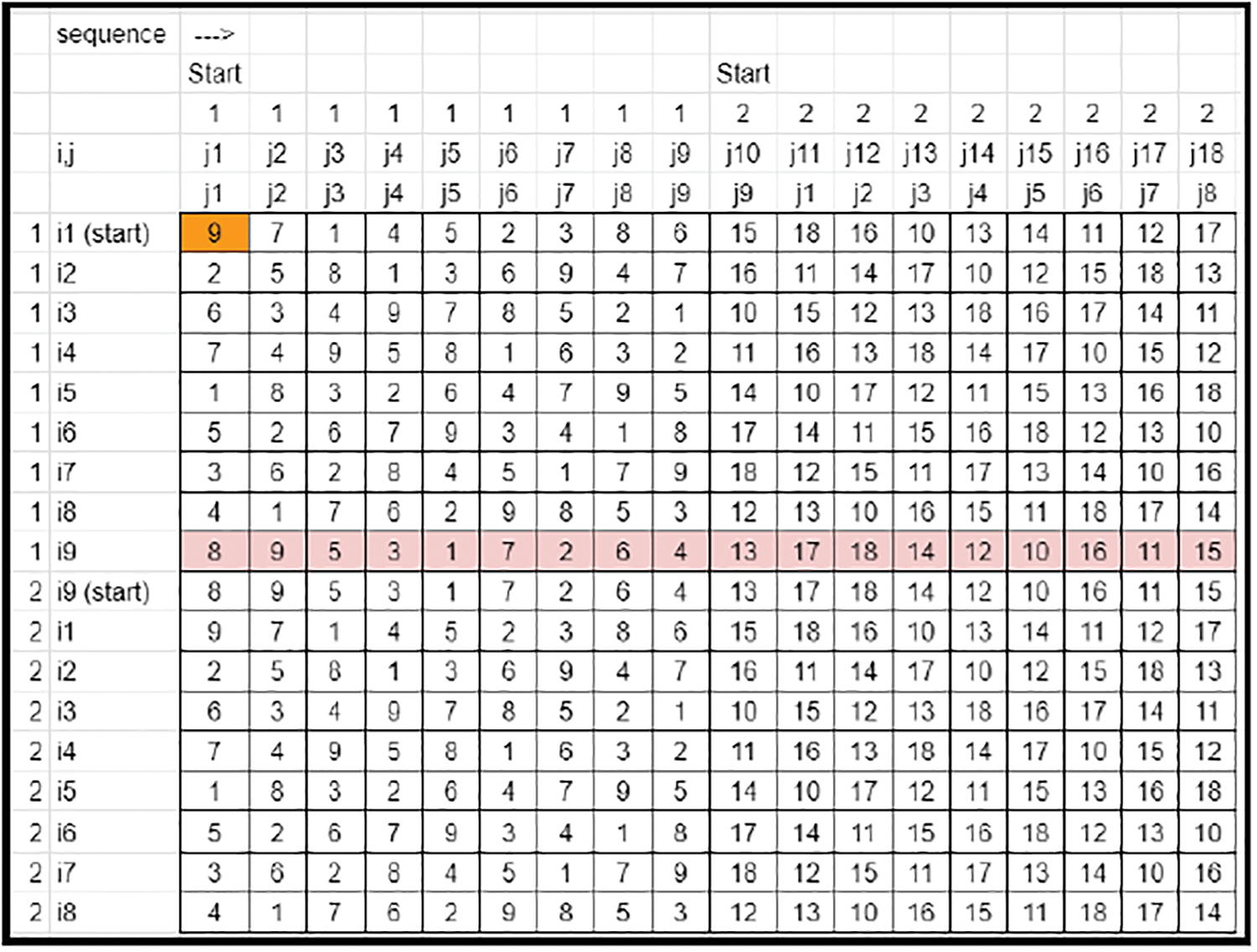
Figure 7: Key matrix-sequencing across columns
• The first element (0, 0) of the matrix dictates the factor for scaling and shuffling and is saved as prime.
• The transpose of the prime row element defines the scaling of the matrix elements along each row. This way, the entire matrix elements are scaled and range from 1 to N × N. This matrix becomes the Derived key matrix 1 (Refer to Fig. 8).
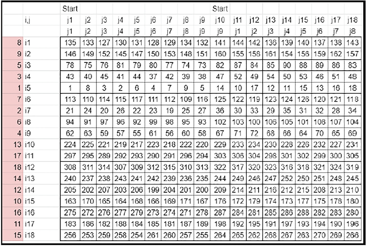
Figure 8: Key matrix-complete sequencing
• The transpose of prime column elements of Derived key matrix 1 defines the downward rotational shifts of the derived matrix elements along each column.
• Since the maximum rotational downshifting is limited by N, the prime column element factors (Refer to Fig. 9) are modulo operated by N (Refer to Fig. 10) and then applied to the matrix.
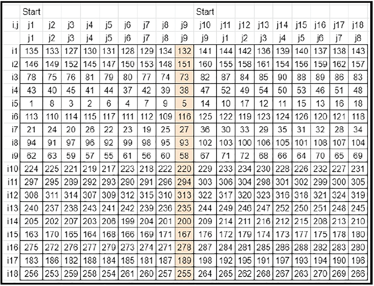
Figure 9: Sampled derived key's matrix 1 with prime column
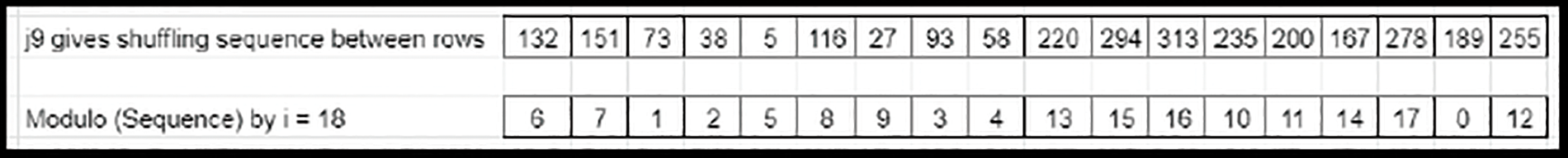
Figure 10: Modulo calculation
• The entire matrix elements are shuffled along the vertical axis (Refer to Fig. 11). This matrix becomes the derived key matrix 2 (Refer to Fig. 12).
Figure 11: Pattern-based downward rotation
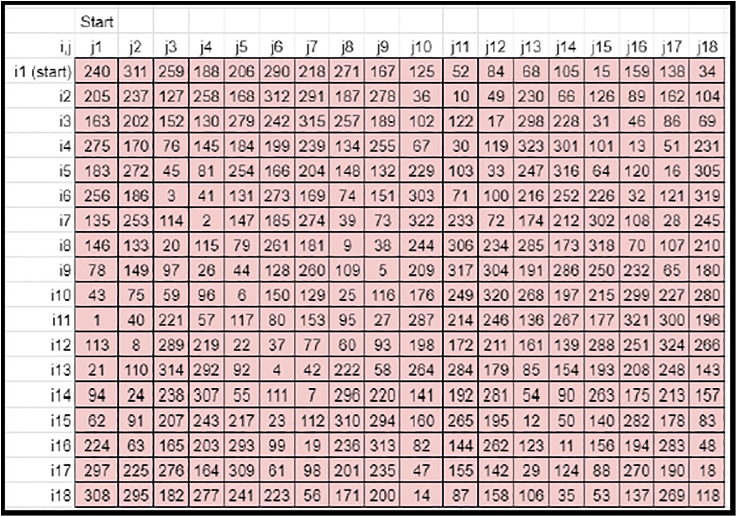
Figure 12: Sample derived key matrix 2
• The prime column elements of derived key matrix 1 define the rightward rotational shifts of derived matrix elements along each row (Refer to Fig. 13).
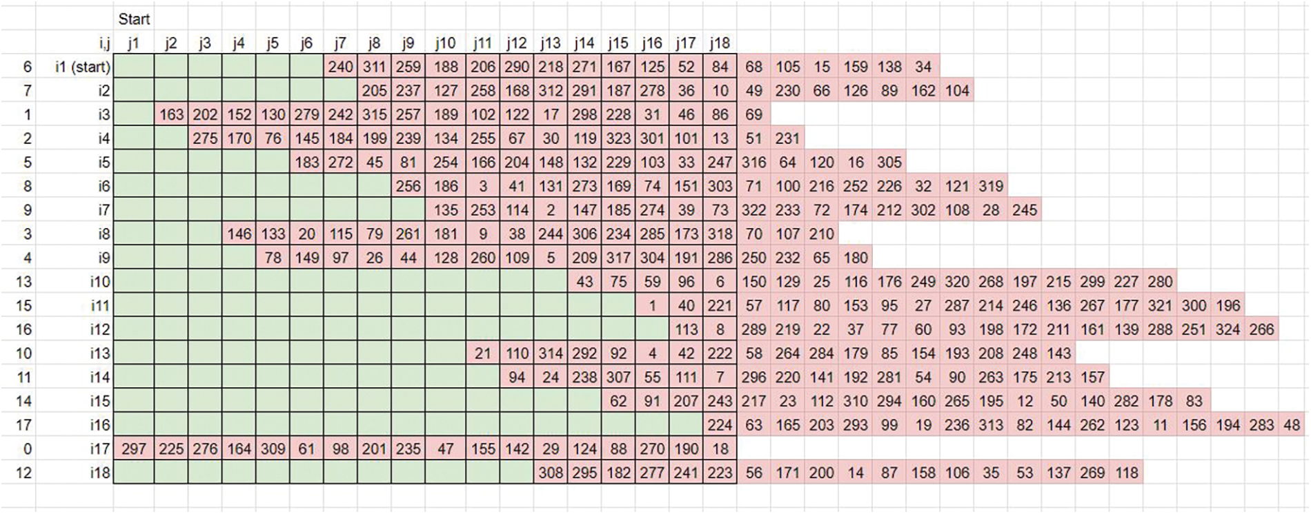
Figure 13: Pattern-based rightward rotation
• Since the maximum shift is limited by N, the prime column element factors are modulo operated by N and applied to the matrix.
• The entire matrix elements are shuffled along the Horizontal axis. This matrix becomes the derived key matrix 3.
• The linear down and right rotational shifts are balanced by the standard zig-zag up and left rotational shifts (Refer to Fig. 14).
Figure 14: Count-based up-left zigzag shifts
• The iteration of shifts is defined by the first element (0, 0) of the Derived key matrix 3. The resultant matrix becomes the final key’s matrix for Image encryption.
• The zig-zag shift of the colored elements can be compared (Refer to Figs. 15 and 16).
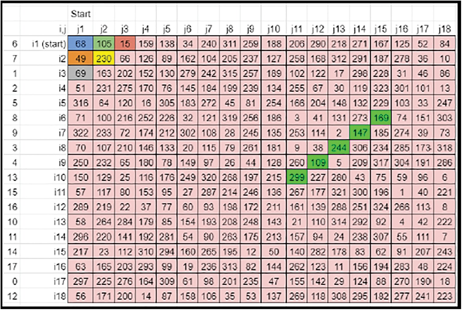
Figure 15: Case 1 sample derived key matrix 3-before zig-zag shift
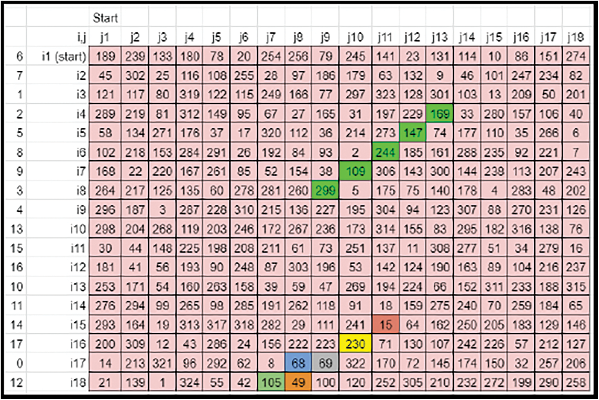
Figure 16: Case 1 sample derived key matrix 3-after zig-zag shift
• The generated key is then written into a text file and saved for further encryption procedures.
6 Crypto Key Generation–Cases 2 & 3
• The image size (M × N) may not be a multiple of the key’s size (n × n). Hence the key rows and columns need to be truncated or expanded by adequate offsets. If N is not divisible by n, expand the column size from N to Nnew, so that it is divisible by n (Refer to Figs. 17 and 18).
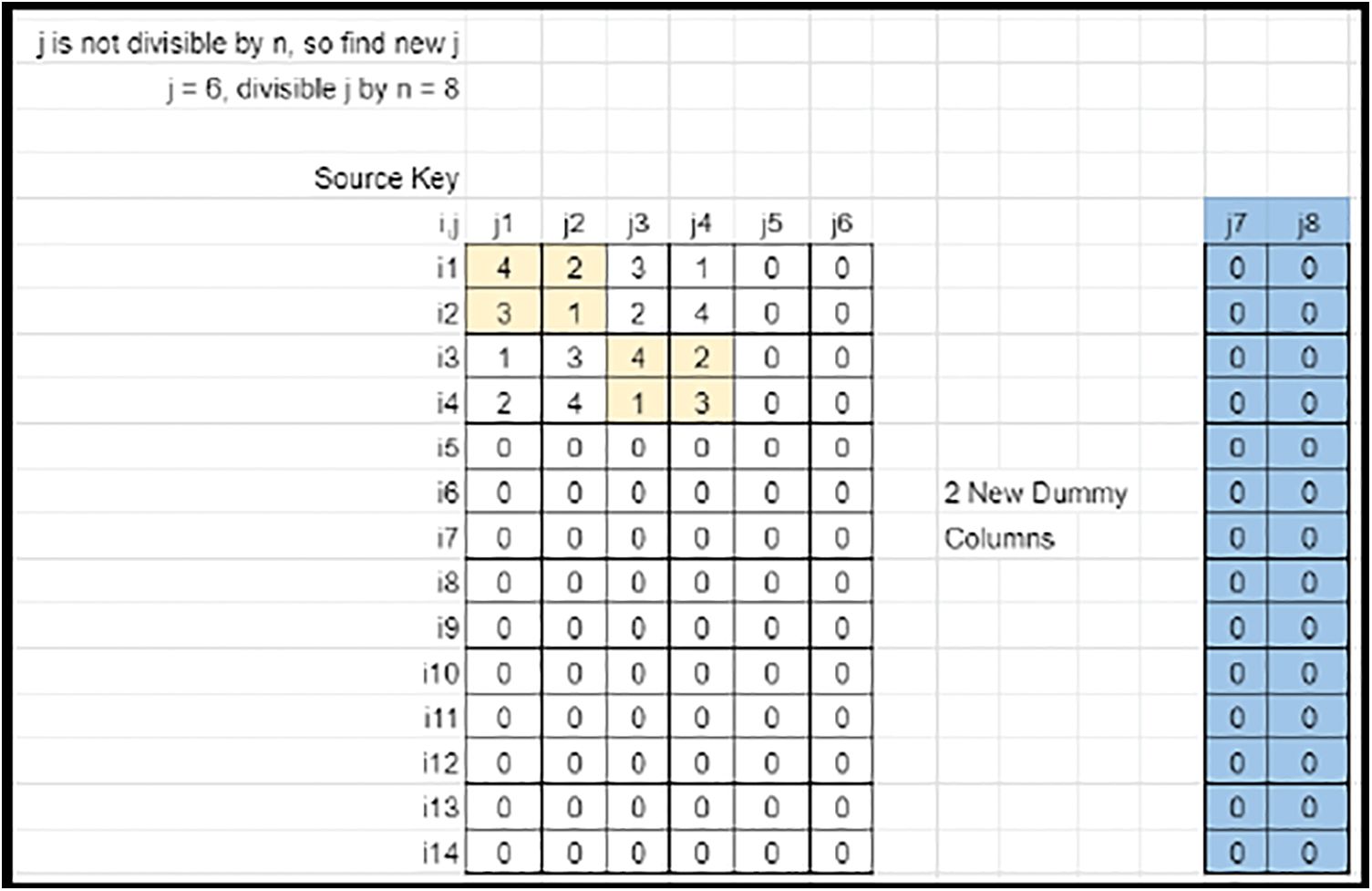
Figure 17: Sudoku matrix (Case 2) fit into key matrix with column mapping
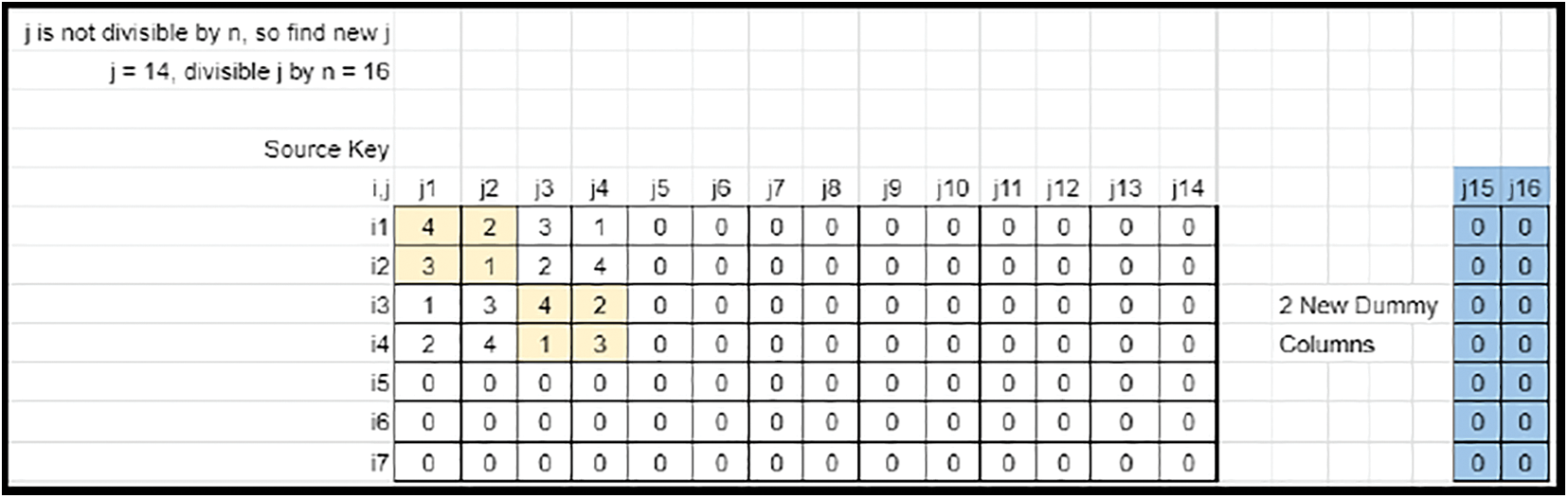
Figure 18: Sudoku matrix (Case 3) fit into key matrix with column mapping
• The iteration the key needs to be scaled is stored as ‘ifactor’ along the Vertical axis (Top to down) and as ‘jfactor’ along the Horizontal axis (Left to right).
• The key is expanded along the Horizontal axis in each row by filling right rotated (single shift) values of the previous set of values. This method fills all elements of the base key rows.
• The key is expanded along the vertical axis in each column by filling down rotated (single shift) values of the previous set of values. This method fills all elements of the matrix.
• If N is expanded to Nnew, the Last segment in each row needs to be sorted. The Highest Nnew−N elements gets cornered in the last column and removed (Refer to Figs. 19–21).
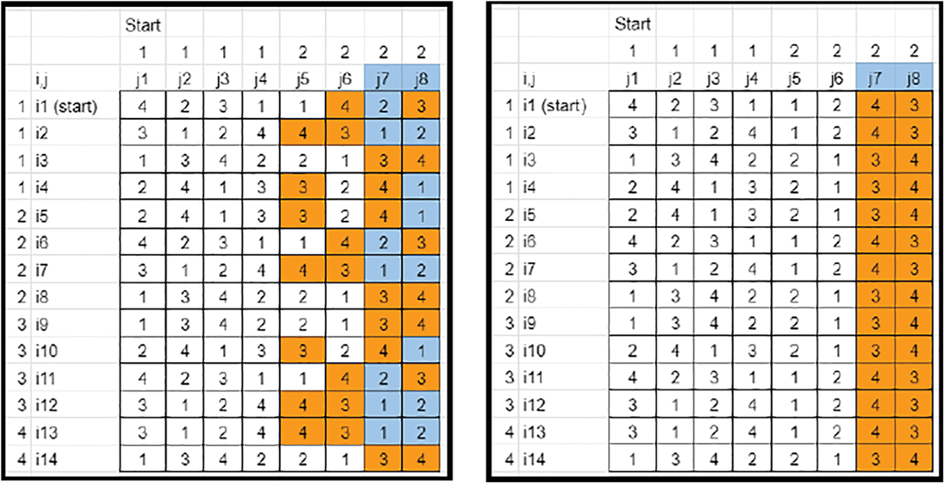
Figure 19: Key matrix-element sorting and isolation (Case 2)
Figure 20: Key matrix-element sorting (Case 3)
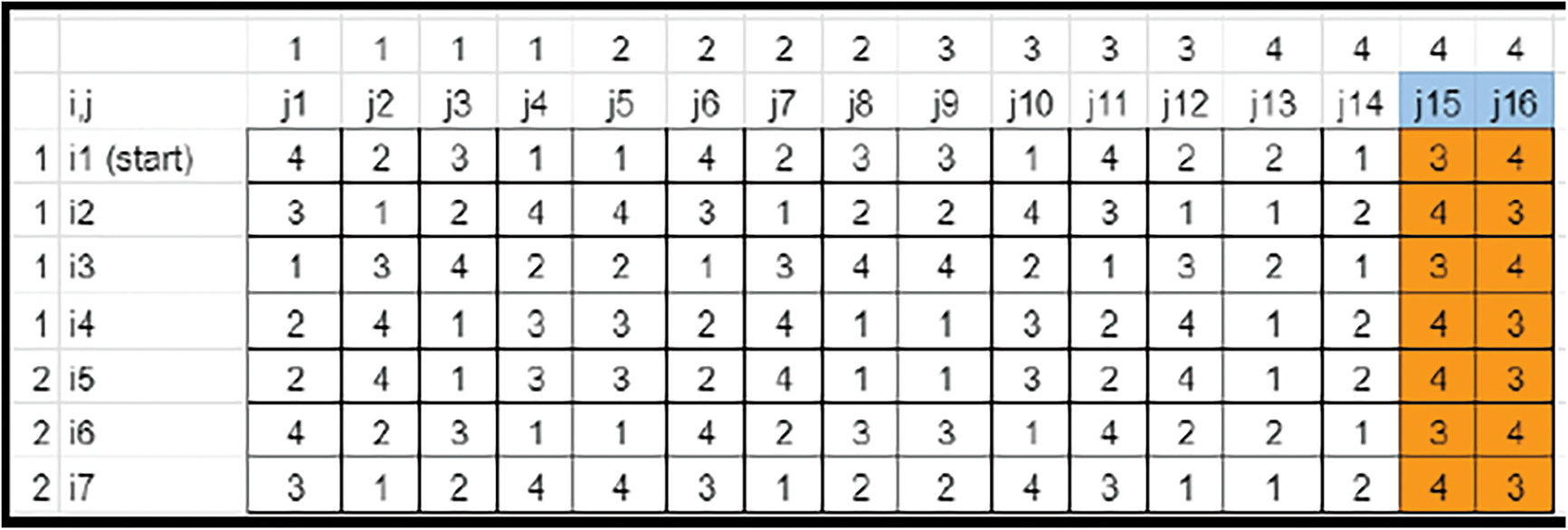
Figure 21: Key matrix-element isolation (Case 3)
• Also, while sorting the patterns of segments, the leftover elements in each row must be assigned by numbers 1 to the max. The Nnew−N columns are removed (Refer to Figs. 22 and 23).
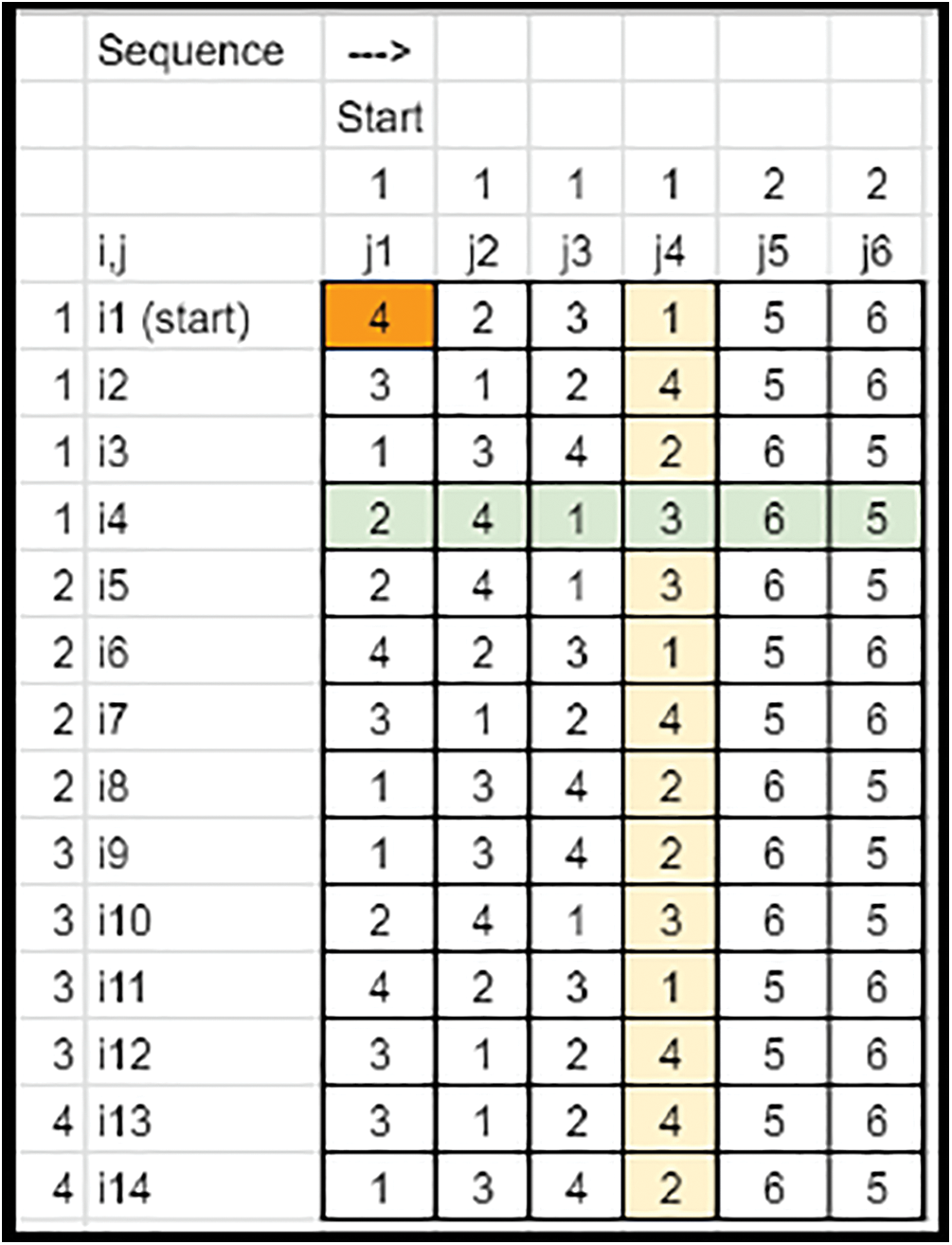
Figure 22: Key matrix-columns removed (Case 2)
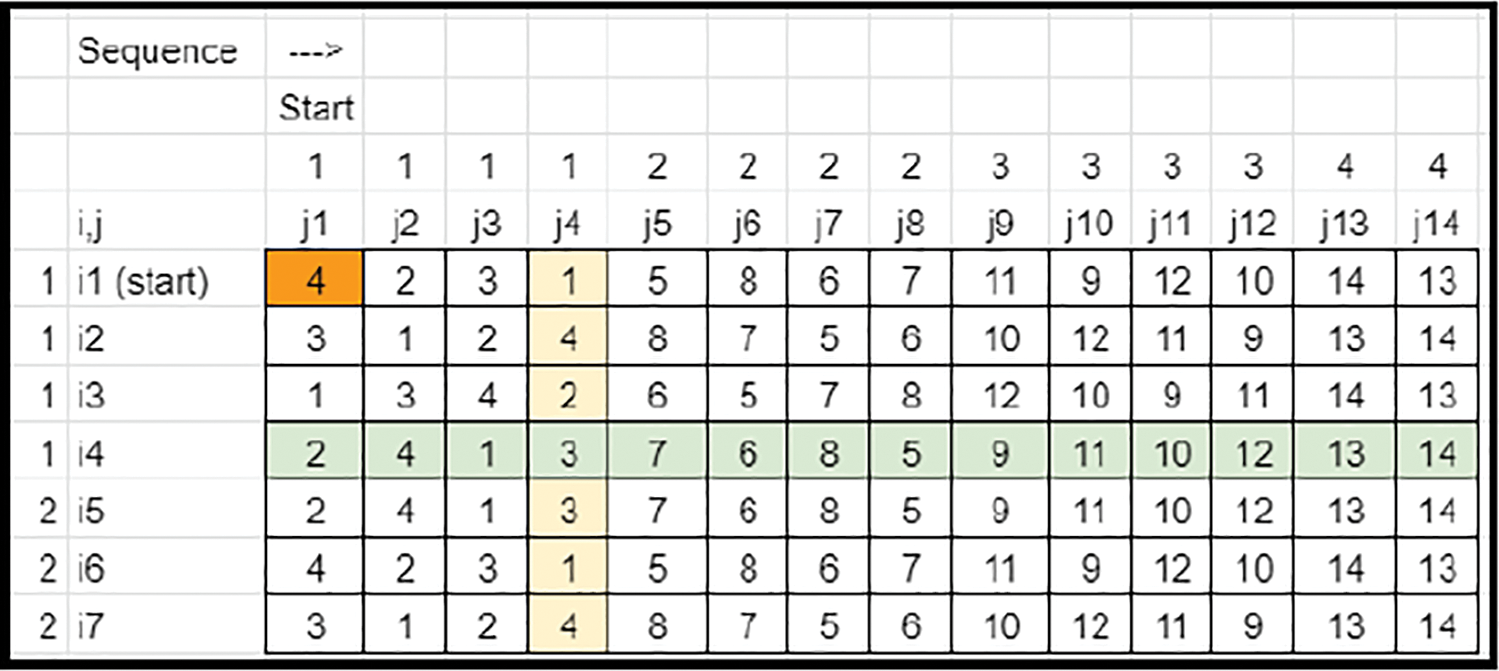
Figure 23: Key matrix-columns removed (Case 3)
• All the row elements are scaled by the corresponding ‘jfactor’ values so that the values get limited within 1 to N.
• The first element (0, 0) of the matrix is the factor for scaling and shuffling in the further steps. Hence, it is saved as prime.
• The Transposition of prime row elements defines the scaling of the matrix elements along each row. Since M is greater than N, the size of the elements does not match (undersized) with the row count. Hence, the prime column end elements are appended to compensate for the shortage in row scaling factor (Refer to Fig. 24). Case 2 involves appending. In contrast, for Case 3, Since M < N, the size of elements does not match (oversized) with the row count and hence it involves truncation (Refer to Fig. 25).
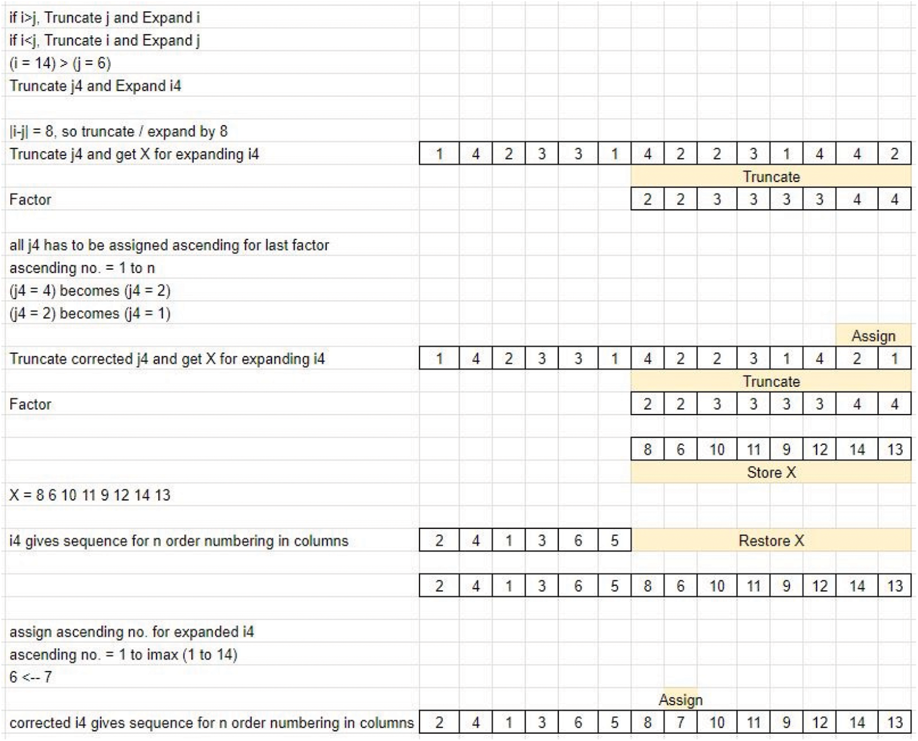
Figure 24: Sequencing-arrival of pattern-Case 2
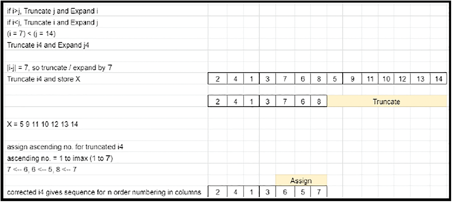
Figure 25: Sequencing-arrival of pattern-Case 3
• Since the sequence is disturbed due to the appending, the expanded prime row elements are sorted from 1 to maximum value, based on the sequence in the expanded elements.
• With the conditioned prime row elements, all the matrix elements get scaled and range from 1 to M × N. This matrix becomes the Derived key matrix 1.
• The Transpose of prime column elements of Derived key matrix 1 defines the downward rotational shifts of the derived matrix elements along each column. Since M is greater than N, the size of the elements does not match (oversized) with the column count. Hence, the end elements of the transposed prime column of derived key matrix 1 are truncated to compensate for the excess in column shuffling factor (Refer to Fig. 26), which is applicable for Case 2. Expansion is involved by appending the earlier truncated content (Refer to Fig. 27) for Case 3.
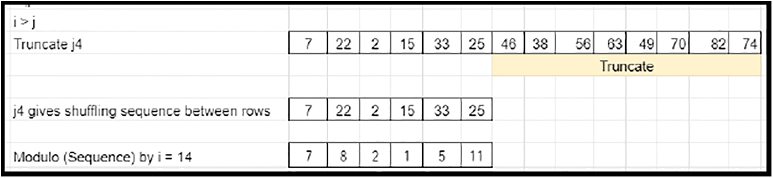
Figure 26: Shuffling-arrival of pattern-Case 2
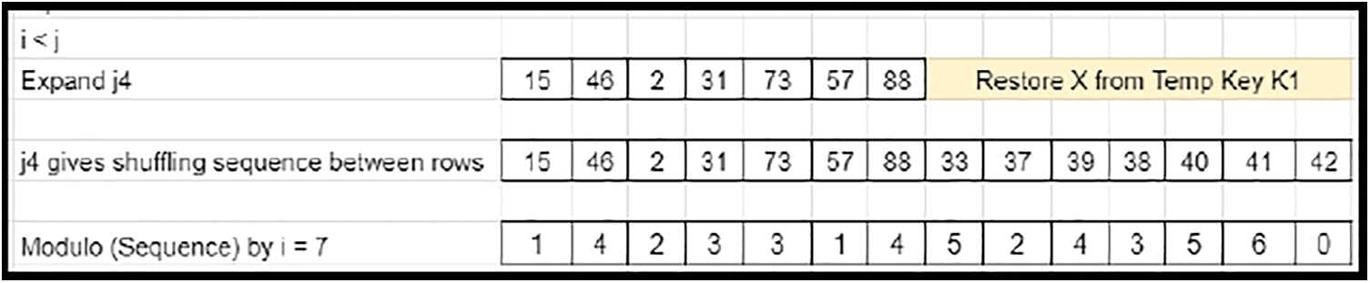
Figure 27: Shuffling-arrival of pattern-Case 3
• Since the maximum rotational downshifting is limited by M, the truncated prime column element factors are modulo operated by M.
• With the conditioned prime column elements, all the matrix elements get shuffled along the vertical axis. This matrix becomes the derived key matrix 2.
• Since the maximum shift is limited by N, the conditioned prime column element factors are modulo operated by N.
• These derived prime column elements of derived key matrix 1 define the rightward rotational shifts of the derived matrix elements along each row. The entire matrix elements get shuffled along the horizontal axis. This matrix becomes the derived key matrix 3.
• The linear down and right rotational shifts are balanced by the standard zig-zag up and left rotational shifts. The shift count is defined by the first element (0, 0) of the Derived key matrix 3. The Resulting matrix becomes the final key matrix for image encryption for Case 2 (Refer to Fig. 28) and Case 3 (Refer to Fig. 29).
Figure 28: Sample final crypto key-Case 2
Figure 29: Sample final crypto key-Case 3
• The generated key is then written into a text file and saved for further encryption procedures.
Since the crypto key and the image are of the same size, Encryption is a direct position transformation of the pixels (Type-A) or the RGB sub-pixels (Type-B).
This type of image encryption is a direct image scrambling. In image encryption (Type-A), RGB sub-pixels are jointly position-transformed in the pattern defined by the crypto key. The steps involved in Type-A encryption are given below:
• The crypto key is read from a Text file and stored in a two-dimensional matrix of size M × N.
• The image file to be encrypted is read. The pixel data is stored in a three-dimensional matrix of size M × N × 3. M × N represents the row width (Breadth) and column width (Length), while the pixel color information is available as three parametric values corresponding to R, G and B.
• This image matrix is converted into a two-dimensional matrix of size M × N × 3 by stretching each row one after another without disturbing the RGB data.
• The position of the pixel data is shuffled in a single dimension ranging from 1 to M × N, based on the crypto key.
• The shuffled image matrix is converted back to a 3-dimensional matrix of size M × N × 3 by linear sequencing in steps of M.
• The encrypted images (Refer to Figs. 30 to 33) are saved for analysis and reference.
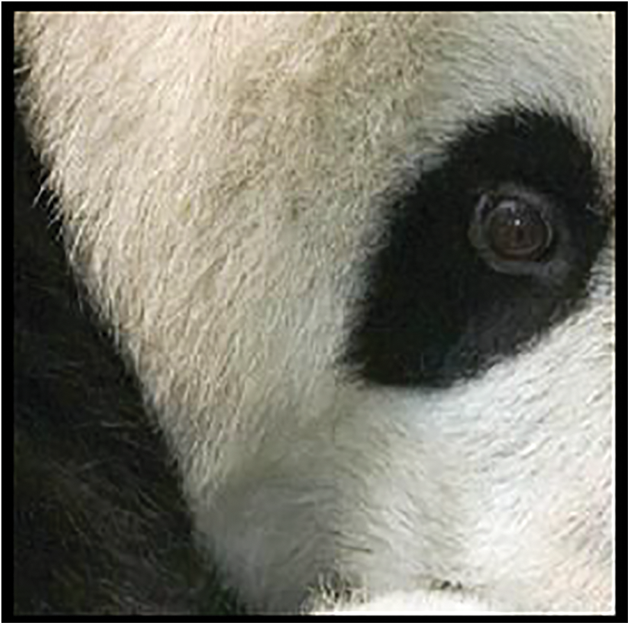
Figure 30: Source image-1 (270 × 270 pixels) -scaled down
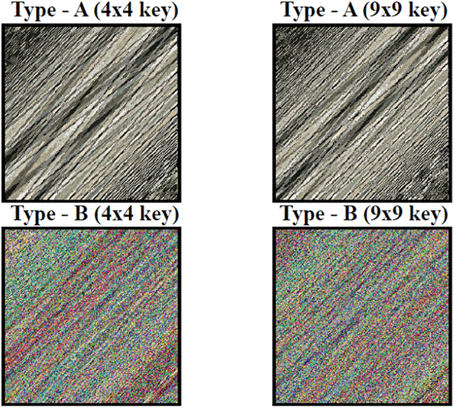
Figure 31: Encrypted images (Type-A and B) for source image-1-scaled down
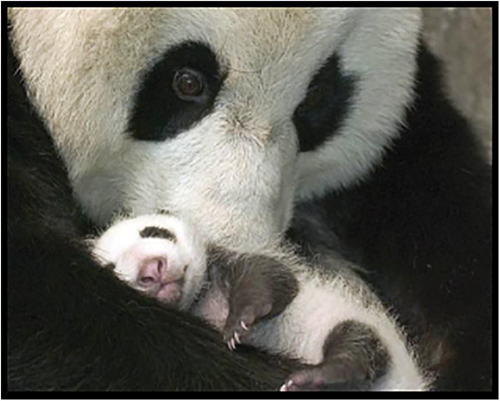
Figure 32: Source image-2 (480 × 600 pixels) -scaled down
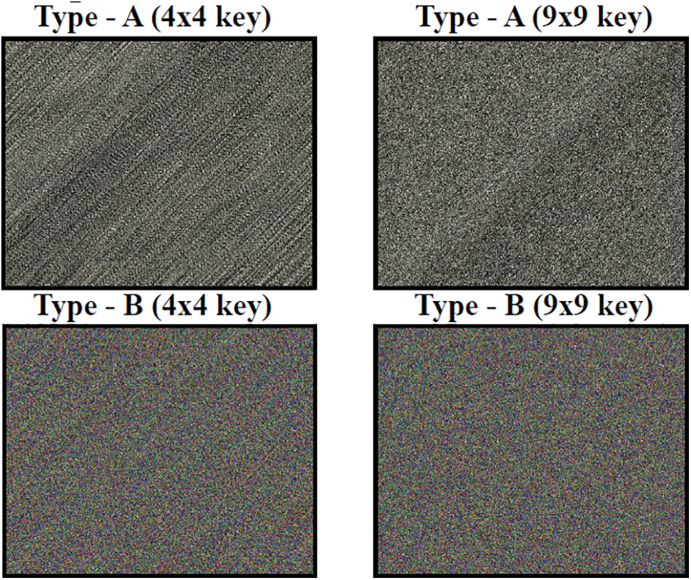
Figure 33: Encrypted images (Type-A and B) for source image-2-scaled down
This type of image encryption is image scrambling with partial diffusion. In the image encryption (Type-B), RGB sub-pixels are differently position-transformed in the pattern defined by the crypto key. The Steps involved in Type-B encryption are given below:
• The crypto key is read from a Text file and stored in a two-dimensional matrix of size M × N. Three keys corresponding to R, G and B, each of one-dimensional matrix of size M × N, are derived from the crypto key.
• The crypto key for B-pixels is obtained by simple conversion of the crypto key from a two-dimensional matrix of size M × N to one-dimensional matrix of M × N by stretching each row one after another without disturbing the key.
• The crypto key for B-pixels is read from end to start. The reversed pattern key is stored as the crypto key for G-pixels.
• The crypto key for B-pixels is shifted by half its length and the shuffled pattern key is stored as the crypto key for R-pixels.
• The image file to be encrypted is read and stored in 3 separate one-dimensional matrices corresponding to R, G and B, each of size M × N. M × N represents the row width (Breadth) and column width (Length) and remains the same for all the color matrices.
• Each color matrix is converted into a one-dimensional matrix of size M × N by stretching each row one after another without disturbing the color data.
• The positions of the pixel data in all the color matrices are shuffled based on the respective crypto keys in a single dimension ranging from 1 to M × N.
• Each color matrix is converted from a one-dimensional matrix of size M × N into a two-dimensional matrix of size M × N by linear sequencing in steps of M.
• All 2D matrices are merged by weighting the R, G and B values to form the net encrypted image.
• The encrypted images (Refer to Figs. 30 to 33) are saved for analysis and reference.
The performance metrics are grading the encryption technique. Many methods are available for assessing the encryption efficiency. However, few of them are used in these sections for validation, namely the histogram analysis, correlation coefficient analysis, differential measure analysis and Noise analysis.
This method is employed as a performance metric to assess and derive a graphical outcome on the Diffusion characteristics of the encryption technique [23]. The following steps are involved in the analysis:
• The source and the encrypted images are converted into equivalent grayscale images. The absolute difference between the converted grayscale image data is calculated for each pixel position. M × N data, each with an intensity value ranging from 0 to 255 in grayscale, will be obtained.
• Two hundred fifty-six grayscales are weighted by the data points containing respective intensities.
• The average is found for the pixel count with grayscale values of 0 and 255. The result is summed with the sum of products of all remaining grayscale values and corresponding pixel count. The result is divided by the total pixel count (M × N).
• The Histogram deviation [25] is estimated using the equation,
One of the performance metrics to assess the correlation between the adjacent pixels in an image is the correlation coefficient. For an actual image, there is no sudden change in the adjacent pixels, hence the correlation coefficient is almost unity. This metric must be as low as possible for better encryption [23]. The following steps are involved in this analysis:
• The mean grayscale value is found for the source image by adding the grayscale values and dividing by the total pixel count (M × N) in an image.
• The variance for each grayscale value is found by calculating the difference between each value and the derived mean grayscale value. Difference values are squared, summed and then divided by the total pixel count (M × N). This calculation is done for encrypted images.
• The difference between each grayscale value and the derived mean grayscale value of the source image is multiplied by that of the encrypted image. The products obtained for M × N pixels are summed and divided by the total pixel count (M × N). Cross-correlation value divided by the product of square roots of autocorrelation values of the source and the encrypted images gives the correlation coefficient).
• The Correlation coefficient [25] is estimated using the equation, CC = cov(x, y)/√D(x) ∗ √D(y), where D(x) is given by
8.3 Differential Measure (NPCR)
For overcoming a differential attack, the original image could result in an encrypted image with notable impact. The Number of Pixel Change Rate (NPCR) is a standard measure to assess such impacts. NPCR is used to measure the percentage of the pixel count changed in ciphertext after making a slight change (one-pixel change) in plaintext. T, the theoretical greatest upper boundary of the NPCR is 100% [1]. The following steps are involved in the NPCR analysis:
• The encrypted image for the actual image is saved as a grayscale matrix.
• Range number is chosen between 1 and M × N positions. Random values are chosen between 0 and 255 for RGB color intensities of the chosen pixel.
• The actual image is subjected to a single random pixel change based on the pixel position and values. The 1-pixel variation in the actual image is subjected to Encryption.
• A comparison is made between the encrypted image of the actual image and that of the 1-pixel varied actual image. The number of unchanged pixels is divided by the total pixel count.
• The final result is multiplied by 100 for percentage representation. The obtained result gives the number of pixel change rate (NPCR).
• The NPCR [25] is estimated using the equation,
8.4 Visual Observation of Difference Image
The pattern of the actual image remains the same when it is posed on uniform (almost) distributed data. The uniformity is tested with the encrypted data by computing the absolute difference between the actual and the encrypted images. If the resultant image still possesses the pattern of the actual image, the Encryption is a well-distributed uniform pattern (Refer to Fig. 34).
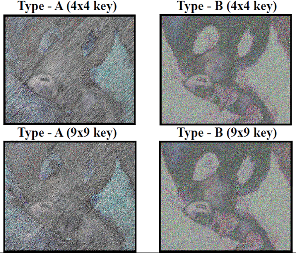
Figure 34: Difference images (Type-A and B) -scaled down
8.5 Peak Signal to Noise Ratio (PSNR)
The Peak Signal to Noise Ratio (PSNR) is a metric to assess the Noise immunity of the algorithm. PSNR measures the proportion of peak signal strength for peak corrupting noise strength. PSNR is expressed in decibels since the ratio covers a wide range of values. The Higher the PSNR, the Encryption quality is better. The following steps are involved in the PSNR analysis:
• The product of the row and column sizes and square of maximum intensity (255) is reserved as the Numerator.
• The Squares of Intensity differences between Source and Decrypted images are summed and reserved as the Denominator.
• The Ratio of the Numerator to Denominator is converted from linear to a logarithmic scale. The obtained result gives the Peak Signal to Noise Ratio (PSNR).
• The PSNR [25] is estimated using the equation,
Upon summarizing the performance metrics, pixel and sub-pixel transformations using 4 × 4 and 9 × 9 keys have different characteristics towards the plain text and differential attacks (Refer to Table 1).
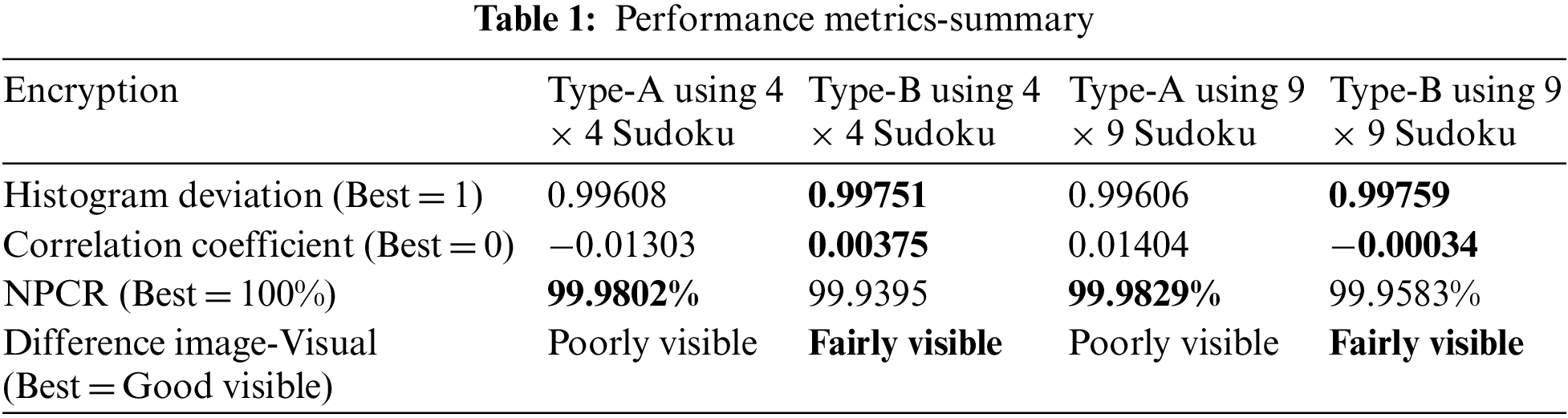
Both encryption have good performance metrics. Type-B Encryption seems to have better shuffling than Encryption Type-A, which is visible in the histogram deviation, the difference image and the low correlation coefficient. Encryption Type-A is better than Type-B encryption for Differential attacks. Type B encryption is superior when used with sudoku keys. There are four classical types of attacks, namely, Cipher only attack, Known plaintext attack, Chosen cipher attack and Chosen plaintext attack.
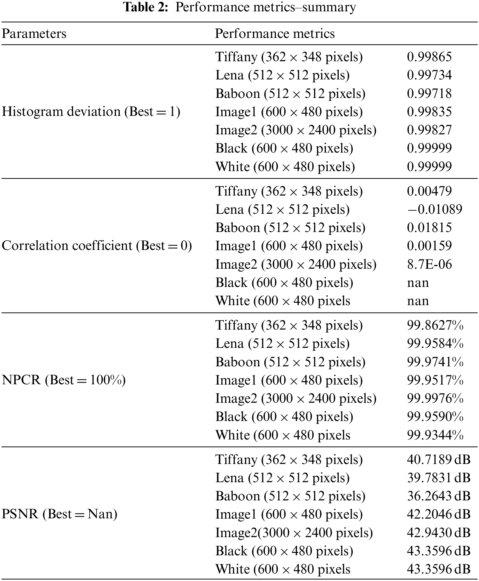
White and black images are used by attackers to find the keys [26]. The Sudoku-based encryption method is susceptible to plain images (Refer to Figs. 35 and 36). which is evident from the key-based analysis and differential attack analysis outcomes (Refer to Table 2).

Figure 35: White input image and encrypted output-600 × 480 pixels (scaled down)

Figure 36: Black input image and encrypted output-600 × 480 pixels (scaled down)
In this paper, the attempt to apply the Sudoku key in the field of cryptography is interesting and efficient, without any compromise in Encryption. An additional advantage of using the sudoku solution as a crypto key is that the key need not be stored for Encryption or Decryption. The key can be reverse sudoku-ed. The clue is stored with details such as the element value and position. A Trade-off exists between the compacted key’s size and the complexity. The main advantage of this algorithm is that this method is independent of Image size, resistant to all the classical attacks, has a high index of performance metrics and has compact key storage. The average throughput for this encryption algorithm approaches 1Mbps, which is very low due to the limitations of the conventional Google Colaboratory engine. Due to this limitation, comparative speed performance is not carried out. The actual throughput would be much better when executed in a proper processing engine. The future scope of this work is to attempt three-dimensional shifting of keys to perform RGB shuffling robustly. Multi-staged Encryption through index referencing and number flow pattern-based matrix shuffling could add more points to the efficiency of cryptography. Moving frame encryption can also be done using Sudoku solutions.
Acknowledgement: The authors also gratefully acknowledge the helpful comments and suggestions of the reviewers, which have improved the presentation.
Funding Statement: The work of U.F.-G. was supported by the government of the Basque Country for the ELKARTEK21/10 KK-2021/00014 and ELKARTEK22/85 Research Programs, respectively.
Author Contributions: M. A. P. Manimekalai–Conceptualization and experimentation; M. Karthikeyan–Investigation and resource collection; I. Thusnavis Bella Mary–Framing of algorithm and formal analysis. K. Martin Sagayam–Manuscript review and editing; Ahmed A. Elngar–Statistical details of the existing work; Unai Fernandez-Gamiz–Language correction; Hatıra Günerhan–Plagiarism check and removal.
Availability of Data and Materials: There is no availability data and materials.
Conflicts of Interest: The authors declare that they have no conflicts of interest to report regarding the present study.
References
1. X. Zhang, L. Wang, Y. Niu, G. Cui and S. Geng, “Image encryption algorithm based on the H-fractal and dynamic self-invertible matrix,” Hindawi Journal-Computational Intelligence and Neuroscience, vol. 12,pp. 1–12, 2019. [Google Scholar]
2. S. Gao, R. Wu, X. Wang, J. Wang, Q. Li et al., “A 3D model encryption scheme based on a cascaded chaotic system,” Elsevier Signal Processing, vol. 202, pp. 1–13, 2023. [Google Scholar]
3. C. Wnag, B. Ma, Z. Xia, J. Li, Q. Li et al., “Stereoscopic image description with Trinion fractional-order continuous orthogonal moments,” IEEE Transactions on Circuits and Systems for Video Technology,vol. 32, no. 4, pp. 1998–2012, 2022. [Google Scholar]
4. G. S. Chandel, V. Sharma and U. P. Singh, “Different image encryption techniques-survey and overview,” International Journal of Advanced Research in Computer Science and Software Engineering, vol. 3, pp. 434–437, 2013. [Google Scholar]
5. M. A. B. Younes and A. Jantan, “Image encryption using block-based transformation algorithm,” IAENG International Journal of Computer Science, vol. 35, no. 1, pp. 1–9, 2006. [Google Scholar]
6. M. A. B. Younes and A. Jantan, “An image encryption approach using a combination of permutation technique followed by encryption,” International Journal of Computer Science and Network Security,vol. 8, no. 4, pp. 191–197, 2008. [Google Scholar]
7. A. Nag, J. P. Singh, S. Khan, S. Ghosh, S. Biswas et al., “Image encryption using affine transform and XOR operation,” in IEEE Int. Conf. on Signal Processing, Communication, Computing and Networking Technologies, Thuckalay, India, pp. 309–312, 2011. [Google Scholar]
8. Q. Sun, W. Yan, J. Huang and W. Ma, “Image encryption based on bit-plane decomposition and random scrambling,” in Proc. of CECNet, Yichang, China, pp. 2630–2633, 2012. [Google Scholar]
9. Q. A. Kester, “A cryptographic image encryption technique based on the RGB PIXEL shuffling,” International Journal of Advanced Research in Computer Engineering and Technology (IJARCET), vol. 2, no. 2, pp. 848–854, 2013. [Google Scholar]
10. M. M. Abbasi, “Solving sudoku by Sparse signal processing,” Master’s Degree Project Report, KTH Royal Institute of Technology, XR-EE-SB 2015:001, pp. 1–47, 2015. [Google Scholar]
11. V. Kumar and A. Giridhar, “A 2D logistic map and Lorenz-Rossler chaotic system based RGB image encryption approach,” Multimedia Tools and Applications, vol. 80, pp. 3749–3773, 2020. [Google Scholar]
12. A. Vedaldi and B. Fulkerson, 2007. [Online]. Available: https://www.vlfeat.org/overview/plots-rank.html [Google Scholar]
13. Auckland University. [Online]. Available: https://www.cs.auckland.ac.nz/~rklette/CCV-CIMAT/pdfs/B04-AdvancedEdgeDetection.pdf [Google Scholar]
14. S. Jain, 2015. [Online]. Available: https://www.geeksforgeeks.org [Google Scholar]
15. Wikimedia Foundation, 2020. [Online]. Available: https://simple.wikipedia.org/wiki/Fingerprint [Google Scholar]
16. Wikimedia Foundation, 2020. [Online]. Available: https://en.wikipedia.org/wiki/Wikimedia_Foundation [Google Scholar]
17. Y. Xian and X. Wang, “Fractal sorting matrix and its application on chaotic image encryption,” Information Sciences, vol. 547, pp. 1154–1169, 2021. [Google Scholar]
18. L. Liu, Y. Lei and D. Wang, “A fast chaotic image encryption scheme with simultaneous permutation-diffusion operation,” IEEE Access, vol. 8, pp. 27361–27374, 2021. [Google Scholar]
19. J. Gunther and T. Moon, “Entropy minimization for solving sudoku,” IEEE Transactions on Signal Processing, vol. 60, no. 1, pp. 508–513, 2012. [Google Scholar]
20. K. A. Markus and D. Borsboom, 2010. [Online]. Available: https://psycnet.apa.org/record/2010-14802-043 [Google Scholar]
21. Astraware Limited, 2014. [Online]. Available: https://www.sudokuoftheday.com/about/difficulty [Google Scholar]
22. Wikimedia Foundation, 2020. [Online]. Available: https://en.wikipedia.org/wiki/Glossary_of_Sudoku [Google Scholar]
23. M. Bala Kumar, P. Karthikka, N. Dhivya and T. Gopalakrishnan, “A performance comparison of encryption algorithms for digital images,” IJERT, vol. 3, no. 2, IJERTV3IS21325, pp. 2169–2174, 2014. [Google Scholar]
24. Google LLC, 2017. [Online]. Available: https://colab.research.google.com [Google Scholar]
25. C. Chattopadhyay, B. I. Sarkar and D. Mukherjee, “Encoding by DNA relations and randomization through chaotic sequences for image encryption,” arXiv preprint arXiv:1505.01795, 2015. [Google Scholar]
26. X. Zhang, L. Wang, Y. Wang, Y. Niu and Y. Li, “An image encryption algorithm based on hyperchaotic system and variable-step Josephus problem,” Hindawi International Journal of Optics, vol. 2020, pp. 1–15, 2020. [Google Scholar]
Cite This Article
 Copyright © 2023 The Author(s). Published by Tech Science Press.
This work is licensed under a Creative Commons Attribution 4.0 International License , which permits unrestricted use, distribution, and reproduction in any medium, provided the original work is properly cited.
 Downloads
 Citation Tools