
 Submit a Paper
 Propose a Special lssue
 Open Access
ARTICLE

In-Plane Static Analysis of Curved Nanobeams Using Exact-Solution-Based Finite Element Formulation
Department of Mechanical Engineering, Istanbul Technical University, Inonu Cad. No. 65, Istanbul, 34437, Turkey
* Corresponding Author: Ömer Ekim Genel. Email:
Computers, Materials & Continua 2025, 82(2), 2043-2059. https://doi.org/10.32604/cmc.2025.060111
Received 24 October 2024; Accepted 20 December 2024; Issue published 17 February 2025
 View Full Text
 Download PDF
Abstract
Due to their superior properties, the interest in nanostructures is increasing today in engineering. This study presents a new two-noded curved finite element for analyzing the in-plane static behaviors of curved nanobeams. Opposite to traditional curved finite elements developed by using approximate interpolation functions, the proposed curved finite element is developed by using exact analytical solutions. Although this approach was first introduced for analyzing the mechanical behaviors of macro-scale curved beams by adopting the local theory of elasticity, the exact analytical expressions used in this study were obtained from the solutions of governing equations that were expressed via the differential form of the nonlocal theory of elasticity. Therefore, the effects of shear strain and axial extension included in the analytical formulation are also inherited by the curved finite element developed here. The rigidity matrix and the consistent force vector are developed for a circular finite element. To demonstrate the applicability of the method, static analyses of various curved nanobeams subjected to different boundary conditions and loading scenarios are performed, and the obtained results are compared with the exact analytical ones. The presented study provides an accurate and low computational cost method for researchers to investigate the in-plane static behavior of curved nanobeams.Keywords
From nanoelectromechanical systems (NEMS) and energy systems to biosensors and cancer treatments, nanostructures have become key components in engineering applications in the twenty-first century [1–5]. The need for more precise and successful nano-scale mechanical modeling brought about by this widespread use is one of the emerging topics in mechanical engineering today [6–8]. One of the significant features of nanostructures is size dependency, and the mechanical framework developed to investigate the structural behavior should capture this phenomenon [9,10]. Within the framework of continuum mechanics, researchers have proposed various advanced theories for this purpose [11]. One of these theories is the nonlocal theory of elasticity introduced by Eringen and Edelen [12]. Like Aifantis’s gradient elasticity theory, a widely used theory in material science, Eringen’s nonlocal theory of elasticity introduces one length scale parameter [13]. However, opposite to Aifantis’s strain-gradient theory, Eringen’s nonlocal theory of elasticity is a stress-gradient theory that can take into account the size effect by assuming stress in any arbitrary point in the media is not only determined by the strain in the same point but also determined by all other points in the media [14] and presents a suitable framework to investigate the mechanical behaviors of structures at the nano-scale [15–19]. More detailed comparisons of both approaches are available in [13,20,21]. Although Eringen’s nonlocal theory of elasticity was initially proposed in the integral form, due to solution difficulties arising from integral representation, Eringen later proposed an equivalent differential form [22], and it paved the way for the study of mechanical behaviors of various nanostructures adopting the nonlocal theory of elasticity. Discussions on recent theoretical advancements in the nonlocal theory of elasticity are available in [23].
From the structural mechanics point of view, most nano-scale structural elements are generally suitable for one-dimensional modeling due to their geometry and loading conditions. Thus, researchers generally investigate the mechanical behavior of such nanostructures using various one-dimensional kinematic models proposed for their equivalents at macro-scale [24–27]. In this sense, most of the studies analyzed static [24,28–30], dynamic [31–35], and buckling [36] behaviors of one-dimensional straight nanostructures by using different kinematic models and solution methods.
In many applications, it is necessary to study curved nanobeams rather than straight one-dimensional nanostructures. For example, nanoresonators, which have a wide range of application potentials from radio communication to nano-sized mass spectrometers due to their ability to vibrate at very high frequencies, can have a curved axis [37–40]. These curved structures are also good candidates for nanoswitches since they allow switching between two stable equilibrium states without requiring any power input [41]. Also, nanoactuators [42] and nanorings used in nanosensors [43–45] are other vital applications of curved nanobeams. These application examples make the investigation of the mechanical behavior of curved nanobeams important and constitute the primary motivation of this study. Fig. 1 summarizes the application areas of curved nanobeams.
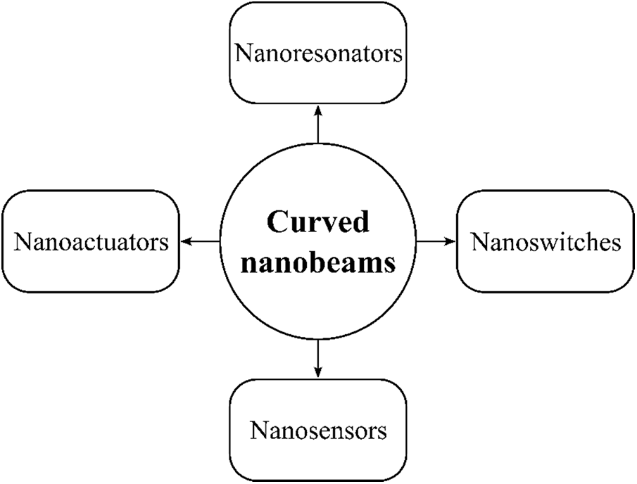
Figure 1: Applications of curved nanobeams in engineering and science
Numerous studies investigated the mechanical behaviors of curved nanobeams by using various kinematics, constitutive models, and solution methods. Arefi et al. investigated the bending behaviors of functionally graded polymer composite graphene nanoplatelets reinforced curved nanobeams resting on an elastic foundation analytically [46]. The authors used the Timoshenko beam model and the Eringen’s differential form to analyze the effects of weight fraction, geometric properties, layer quantity, elastic foundation stiffnesses, and the parameter of nonlocality. Hosseini and Rahmani studied analytically the free vibrations of functionally graded deep and shallow curved nanobeams [47]. The authors adopted the Timoshenko beam model and Eringen’s differential form. By applying Navier’s method, they presented analytical solutions for free vibration behavior, and investigated the effects of the nonlocal parameter, slenderness ratio, opening angle, gradient index, and mode number on structural response. Later, the authors presented a closed-form solution for the flexural and free vibrations of functionally graded curved beams using the Euler-Bernoulli beam model [48]. Arefi and Zenkour employed the sinusoidal shear deformation beam model and the differential form of the nonlocal theory of elasticity to analytically examine the effects of foundation parameters, thermal loading, nonlocal parameter, and curvature on the curved nanobeam resting on elastic foundation [49]. The effect of deepness on the free vibration behavior of a functionally graded curved beam was studied analytically by Hosseini et al. [50]. They employed Euler-Bernoulli beam model and the differential form of the nonlocal theory of elasticity in the study. Apart from these, Tufekci et al. analyzed the in-plane static behaviors of curved nanobeams having nonuniform curvature and cross-section analytically by adopting the differential form of the nonlocal theory of elasticity [51]. The authors employed the initial values method to solve governing differential equations by considering the effects of axial extension and shear deformation on the structural response. They also examined the effects of length-scale parameter, opening angle, loading type, and boundary conditions on the structural response.
In addition to the abovementioned studies, researchers investigated the mechanical behaviors of straight and curved nanobeams via the finite element method. Most of these studies focus on straight-axis finite elements that use interpolation polynomial functions to analyze bending and axial behavior [52,53]. Although it is possible to analyze the mechanical behaviors of curved nanobeams using these finite elements, using a straight-axis beam finite element with a polynomial interpolation function requires large numbers of finite elements to approximate the solution and the curved domain. Another approach to analyzing curved nanobeams within the context of the finite element analysis is utilizing curved finite elements based on the nonlocal theory of elasticity. Since curved finite elements are used instead of straight ones in this approach, the curvature of the nanobeam can be captured with fewer elements than when straight finite elements are used. To this end, researchers proposed various curved finite elements to analyze the mechanical behaviors of curved nanobeams. Merzouki et al. proposed a three-noded finite element to analyze the static behavior of curved nanobeams [53]. The authors adopted a higher-order shear deformation model and the differential form of the nonlocal theory of elasticity. They used quadratic interpolation functions to approximate the axial displacement and the rotation angle while adopting Hermite interpolation functions to approximate transverse contributions. Later, Ganapathi et al. extended this study to analyze the free vibration behavior of curved nanobeams [52]. Using an enriched finite element method, Pham et al. performed free vibration analysis of functionally graded porous curved nanobeams resting on elastic foundations [54]. They considered various kinematic models and employed the differential form of nonlocal elasticity theory. Recently, Manickam et al. studied nonlinear bending behaviors of curved nanobeams by employing a three-noded curved finite element developed based on the sinusoidal shear deformation beam model and the differential form of nonlocal theory of elasticity [55]. In the study, authors approximated the axial displacement and the cross-sectional rotation via quadratic interpolation functions while using Hermite interpolation functions to approximate the transverse displacement.
The literature study has revealed that studies investigating the mechanical behavior of curved nanorods using the finite element method have so far used classical interpolation functions. To the authors’ knowledge, no study investigates in-plane static behaviors of curved nanobeams by using curved finite elements based on exact analytical solutions instead of classical interpolation functions. This study aims to fill this gap by building on the study of Tufekci et al. [56], which introduces a curved finite element to analyze the statics of macro-scale curved beams. In [56], instead of using approximate interpolation functions in the formulation as is done in the classical finite element method, exact analytical expressions acquired from the solution of governing equations of a curved macro-scale beam were utilized to develop a curved finite element by using the classical local theory of elasticity. Eroglu and Tufekci later extended this approach to investigate the free vibration behaviors of macro-scale curved beams [57]. In the present study, the approach that was introduced for the macro-scale curved beams before is employed to analyze the static behavior of curved nanobeams. To this end, authors used the exact analytical expressions previously presented by Tufekci et al. [51] to develop a curved finite element based on the nonlocal theory of elasticity. It should be emphasized that the shear deformation effects are considerable in curved nanobeams with short lengths, thick cross-sections, and larger nonlocal parameters [53]. In such cases, the Timoshenko beam model produces more accurate results than the Euler-Bernoulli beam model. Therefore, authors considered the effects of the shear strain in the formulation alongside the effect of the axial extension. The rigidity matrix and the force vector are obtained for a circular finite element using Eringen’s differential form. Three numerical examples are solved, and the accuracy of the presented approach is shown by comparing the results obtained with the exact analytical ones. Using the presented exact-solution-based finite element formulation, the static analyses of nanoarches can be carried out with low computational costs without sacrificing accuracy.
2.1 Exact Analytical Solutions of In-Plane Static Behavior of a Curved Nanobeam
Fig. 2 describes a nanobeam having a planar curved axis by using a Frenet-Serret frame whose unit vectors (
where
where
and
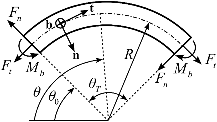
Figure 2: Representation of a curved nanobeam and associated beam parameters used in analytical solution
Mathematically, Eq. (7) is a system of differential equations consisting of variable coefficients, and its solution can be calculated via the initial values method [58]:
where
Therefore, Eq. (10) can be expressed in matrix form [58]:
Since constant curvature and uniform cross-section assumptions yield a constant coefficient matrix
2.2 Reviewing the Exact-Solution-Based Beam Finite Element Formulation
Unlike the conventional beam finite elements, elements developed via exact-solution-based finite element formulation use exact analytical solutions instead of traditional interpolation functions [56,57]. This section revisits this method to obtain a curved nanobeam’s stiffness matrix and the consistent load vector. As stated above, one can obtain the exact analytical solution of Eq. (7) in the case of a constant coefficient matrix,
Consider an isolated arbitrary curved element of an FE assembly depicted in Fig. 3.
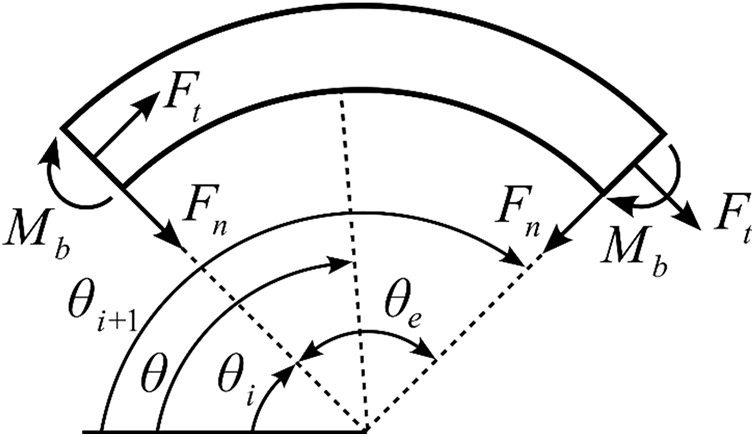
Figure 3: Curved finite element
In Fig. 3,
where
One can also apply the same arrangement to the fundamental matrix
where
Based on these decompositions, the following stiffness matrix,
where
where
3 Numerical Examples and Discussion
Although the approach summarized in Section 2 was first introduced to examine the static behavior of curved beams using the local theory of elasticity [56], it also offers a general matrix structure helpful in investigating the static behavior of curved nanobeams using the nonlocal theory of elasticity. This section presents three numerical examples to demonstrate the method’s applicability in analyzing the in-plane static behaviors of curved nanobeams. All examples assume that cross-sections of nanobeams are solid rectangular profiles. Additionally, the small-scale parameter (

3.1 Example 1: Nanobeams Subjected to Concentrated Normal Tip Force
The first example aims to investigate the in-plane static behavior of cantilever circular nanobeams subjected to concentrated tip forces in the normal direction. To this end, two scenarios having different opening angles, slenderness ratios, and small-scale parameters are considered, as shown in Fig. 4.

Figure 4: Circular nanobeams subjected to normal tip forces: (a) Scenario 1: Quarter circle nanobeam (b) Scenario 2: Half circle nanobeam
Table 2 presents numerical values of parameters used in both scenarios. Both examples assume nanobeams have clamped-free boundary conditions, and the nonlocal parameter is 1.56 nm.

As shown in Fig. 4, both problems can be solved using only one curved finite element since there is no concentrated force in the inner domains of nanobeams. Table 3 shows that dimensionless tip deflection results agree with the analytical solution presented in [51] and [60]. Here, the sign difference between the dimensionless tangential tip deflection results (

Moreover, Fig. 5 presents the effect of the small-scale parameter on the structural response for Scenario 1, as shown in Fig. 4a.

Figure 5: The effect of small-scale parameter on structural response. Solid line: Dimensionless tangential displacement
As shown in Fig. 5, the dimensionless tangential (solid line) and dimensionless normal (dashed line) displacements approach constant values as the small-scale parameter increases. These constant values are displacement values obtained using the local theory of elasticity, and this observation is consistent with Tufekci et al. [51]. For curved beams with a circular axis and a uniform cross-section, exact analytical solutions used to analyze curved beams at the macro-scale are obtained when the small-scale parameter goes to infinity [51,60]. Of course, one can compute exact analytical solutions for a macro-scale curved beam by setting
3.2 Example 2: A Nanoring Subjected to Normal Forces
The second example examines the in-plane static behavior of a nanoring subjected to two symmetrical concentrated forces in the normal direction, as shown in Fig. 6a.

Figure 6: (a) Nanoring subjected to normal forces (b) Finite element idealization
To achieve this, the half model (

3.3 Example 3: Nanobeam Subjected to Distributed Normal Force
The third example is the static analysis of a circular nanobeam in the presence of distributed force, Fig. 7.

Figure 7: Nanobeam subjected to the distributed normal force
Here, it is assumed that the nanobeam with the length
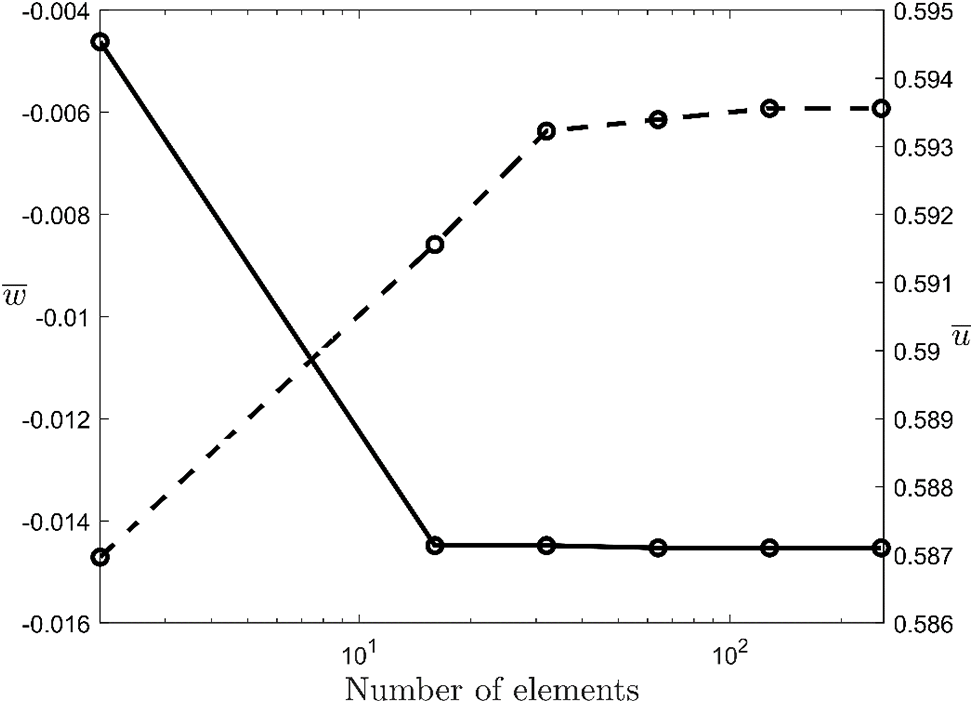
Figure 8: Mesh convergence study for dimensionless tangential displacement
After determining the minimum number of elements that should be used in the analysis, the maximum dimensionless tangential displacement

Curved nanobeams are frequently used in engineering to design nanoactuators, nanosensors, nanoswitches, and nanoresonators. Due to their superior properties, the mechanical behavior of these one-dimensional structures should be studied in detail. One of the approaches used to this end is Eringen’s nonlocal theory of elasticity. This theory enables researchers to comprehensively study curved nanobeams’ static, dynamic, and buckling behaviors.
This study proposes a novel curved nonlocal finite element to study the static behavior of curved nanobeams. Most studies approach the one-dimensional curved domain using straight or curved elements that benefit from approximate interpolation functions. This study proposed a two-noded curved finite element based on the exact analytical solution. In the study where the differential form of Eringen’s nonlocal elasticity theory was used as the nonlocal model and Timoshenko’s beam theory as the kinematic model, the effects of the axial extension of the beam axis were also considered. The stiffness matrix and consistent load vector were directly computed based on the exact analytical solution obtained by the initial values method. Three different numerical examples were studied, and the results obtained were compared with the exact analytical results previously presented in the literature. While nanobeams are subjected to concentrated forces in the first two examples, it is assumed that they are subjected to an asymmetric distributed force in the last example. Analyses reveal that the results computed by the presented approach perfectly agree with the exact analytical ones. In this regard, the authors consider that the study will be helpful to researchers who aim to perform in-plane static analyses of curved nanobeams accurately with a low computational cost.
Finally, it is important to mention the limitations of this study and potential improvements that can be addressed in future studies. First, the functions used in the finite element formulation developed in this study are exact analytical solutions obtained from the solution of a linear differential equation system. Therefore, the method cannot be directly applied in its current form to the study of problems that contain variable coefficients or nonlinear components. On the other hand, it should be especially noted that the presented method has the potential to be applied to a diverse range of problems with appropriate modifications. In this context, dynamic behaviors of curved nanobeams can be studied in subsequent studies based on the current basis and perspective. Similarly, the presented approach can also enable the study of the mechanics of composite nanobeams with multiscale structures through appropriate modifications. The authors plan to focus on these points in future studies.
Acknowledgement: None.
Funding Statement: This work was supported by Scientific Research Projects Department of Istanbul Technical University. Project Number: MGA-2018-41546. Grant receiver: E.T.
Author Contributions: The authors confirm contribution to the paper as follows: study conception and design: Ömer Ekim Genel, Hilal Koç, and Ekrem Tüfekci; data collection: Ömer Ekim Genel, Hilal Koç, and Ekrem Tüfekci; analysis and interpretation of results: Ömer Ekim Genel, Hilal Koç, and Ekrem Tüfekci; draft manuscript preparation: Ömer Ekim Genel, Hilal Koç, and Ekrem Tüfekci. All authors reviewed the results and approved the final version of the manuscript.
Availability of Data and Materials: The data that support the findings of this study are available from the corresponding author, Ömer Ekim Genel, upon reasonable request.
Ethics Approval: Not applicable.
Conflicts of Interest: The authors declare no conflicts of interest to report regarding the present study.
Nomenclature
| The unit vector that refers to the normal direction | |
| The unit vector that refers to the tangential direction | |
| The unit vector that refers to the binormal direction | |
| Tangential displacement | |
| Normal displacement | |
| Rotation angle about the binormal axis | |
| Dimensionless tangential tip displacement | |
| Dimensionless normal tip displacement | |
| Dimensionless bending moment | |
| Tangential tip displacement computed from analytical method | |
| Normal tip displacement computed from analytical method | |
| Dimensionless tangential tip displacement computed from analytical method | |
| Dimensionless normal tip displacement computed from analytical method | |
| Radius of curvature | |
| Angular coordinate | |
| Opening angle | |
| Reference angular coordinate | |
| Angular coordinate of the cross-section at | |
| Angular coordinate of the cross-section at | |
| Finite element opening angle | |
| Force resultant in the tangential direction | |
| Force resultant in the normal direction | |
| Moment resultant in binormal direction | |
| Distributed force in the tangential direction | |
| Distributed force in the normal direction | |
| Distributed moment about the binormal axis | |
| The magnitude of the distributed force | |
| Young’s modulus | |
| Shear modulus | |
| Poisson ratio | |
| Nonlocal parameter | |
| Material constant | |
| Material internal length | |
| Shear correction factor | |
| Cross-sectional area | |
| Depth of cross-section | |
| Moment of inertia about the binormal axis | |
| Length of the curved nanobeam | |
| Slenderness ratio | |
| Dummy integration variable |
References
1. Zhang W, Yan X, Meng Y, Zhang C, Youn S-K, Guo X. Flexoelectric nanostructure design using explicit topology optimization. Comput Methods Appl Mech Eng. 2022;394(3):114943. doi:10.1016/j.cma.2022.114943. [Google Scholar] [CrossRef]
2. Zamzami MA, Rabbani G, Ahmad A, Basalah AA, Al-Sabban WH, Ahn SH, et al. Carbon nanotube field-effect transistor (CNT-FET)-based biosensor for rapid detection of SARS-CoV-2 (COVID-19) surface spike protein S1. Bioelectrochemistry. 2022;143(3):107982. doi:10.1016/j.bioelechem.2021.107982. [Google Scholar] [PubMed] [CrossRef]
3. Meng X, Geng D, Liu J, Li R, Sun X. Controllable synthesis of graphene-based titanium dioxide nanocomposites by atomic layer deposition. Nanotechnology. 2011 Mar;22(16):165602. doi:10.1088/0957-4484/22/16/165602. [Google Scholar] [PubMed] [CrossRef]
4. Baughman RH, Cui C, Zakhidov AA, Iqbal Z. Carbon nanotube actuators. Science. 1999;284(5418):1340–4. [Google Scholar] [PubMed]
5. Son KH, Hong JH, Lee JW. Carbon nanotubes as cancer therapeutic carriers and mediators. Int J Nanomed. 2016;11:5163–85. [Google Scholar]
6. Li C, Chou T-W. A structural mechanics approach for the analysis of carbon nanotubes. Int J Solids Struct. 2003;40(10):2487–99. doi:10.1016/S0020-7683(03)00056-8. [Google Scholar] [CrossRef]
7. Ceballes S, Saunders BE, Abdelkefi A. Nonlocal Timoshenko modeling effectiveness for carbon nanotube-based mass sensors. Eur J Mech-A/Solids. 2022;92(3):104462. doi:10.1016/j.euromechsol.2021.104462. [Google Scholar] [CrossRef]
8. Karami B, Janghorban M, Rabczuk T. Forced vibration analysis of functionally graded anisotropic nanoplates resting on Winkler/Pasternak-foundation. Comput Mater Contin. 2020;62(2):607–29. doi:10.32604/cmc.2020.08032. [Google Scholar] [CrossRef]
9. Saini R, Gopalakrishnan S. Nonlocal boundaries and paradoxes in thermoelastic vibrations of functionally graded non-uniform cantilever nanobeams and annular nanoplates. Structures. 2023 Sep;55(18):1292–305. doi:10.1016/j.istruc.2023.06.095. [Google Scholar] [CrossRef]
10. Barretta R, Čanađija M, Luciano R, de Sciarra FM. On the mechanics of nanobeams on nano-foundations. Int J Eng Sci. 2022;180(2):103747. doi:10.1016/j.ijengsci.2022.103747. [Google Scholar] [CrossRef]
11. Wang J, Yu Y, Zhao X, Sun J, Wang Y, Zhu H. A review on the size-dependent bulking, vibration and, wave propagation of nanostructures. J Phys Condens Matter. 2023;35(29):293001. doi:10.1088/1361-648X/acc62b. [Google Scholar] [PubMed] [CrossRef]
12. Eringen AC, Edelen D. On nonlocal elasticity. Int J Eng Sci. 1972;10(3):233–48. doi:10.1016/0020-7225(72)90039-0. [Google Scholar] [CrossRef]
13. Askes H, Gitman IM. Review and critique of the stress gradient elasticity theories of Eringen and Aifantis. In: Maugin Gérard A, Metrikine AV, editors. Mechanics of generalized continua: one hundred years after the cosserats. New York, NY, USA: Springer New York; 2010. p. 203–10. doi:10.1007/978-1-4419-5695-8_21. [Google Scholar] [CrossRef]
14. Zenkour AM, Abouelregal AE, Alnefaie KA, Abu-Hamdeh NH, Aifantis EC. A refined nonlocal thermoelasticity theory for the vibration of nanobeams induced by ramp-type heating. Appl Math Comput. 2014 Dec;248(16):169–83. doi:10.1016/j.amc.2014.09.075. [Google Scholar] [CrossRef]
15. Nalbant MO, Bağdatli SM, Tekin A. Three-to-one internal resonances of stepped nanobeam of nonlinearity. Zeitschrift Für Naturforschung A. 2024;79(4):363–76. doi:10.1515/zna-2023-0215. [Google Scholar] [CrossRef]
16. Uzun B, Yaylı MÖ, Civalek Ö. Elastic medium and torsional spring effects on the nonlocal dynamic of functionally graded porous nanotubes. Arch Appl Mech. 2024;94(5):1–21. doi:10.1007/s00419-024-02576-8. [Google Scholar] [CrossRef]
17. Lan DM, Dong PV, Thien LG, Tuyen BV, Hai NT. Static bending and vibration of composite nanobeams taking into the effect of geometrical imperfection. J Vib Eng Technol. 2024;12(7):8685–706. doi:10.1007/s42417-024-01384-2. [Google Scholar] [CrossRef]
18. Kianian O, Sarrami S, Movahedian B, Azhari M. PINN-based forward and inverse bending analysis of nanobeams on a three-parameter nonlinear elastic foundation including hardening and softening effect using nonlocal elasticity theory. Eng Comput. 2024. doi:10.1007/s00366-024-01985-1. [Google Scholar] [CrossRef]
19. Tuna M, Kirca M. Bending, buckling and free vibration analysis of Euler-Bernoulli nanobeams using Eringen’s nonlocal integral model via finite element method. Compos Struct. 2017;179:269–84. [Google Scholar]
20. Askes H, Aifantis EC. Gradient elasticity in statics and dynamics: an overview of formulations, length scale identification procedures, finite element implementations and new results. Int J Solids Struct. 2011 Jun;48(13):1962–90. doi:10.1016/j.ijsolstr.2011.03.006. [Google Scholar] [CrossRef]
21. Aifantis EC. On the gradient approach—Relation to Eringen’s nonlocal theory. Int J Eng Sci. 2011 Dec;49(12):1367–77. doi:10.1016/j.ijengsci.2011.03.016. [Google Scholar] [CrossRef]
22. Eringen AC. On differential equations of nonlocal elasticity and solutions of screw dislocation and surface waves. J Appl Phys. 1983;54(9):4703–10. [Google Scholar]
23. Ceballes S, Larkin K, Rojas E, Ghaffari SS, Abdelkefi A. Nonlocal elasticity and boundary condition paradoxes: a review. J Nanopart Res. 2021;23(3):66. doi:10.1007/s11051-020-05107-y. [Google Scholar] [CrossRef]
24. Behera L, Chakraverty S. Static analysis of nanobeams using Rayleigh-Ritz Method. J Mech Mater Struct. 2017;12(5):603–16. doi:10.2140/jomms.2017.12.603. [Google Scholar] [CrossRef]
25. Jiang J, Wang L. Analytical solutions for thermal vibration of nanobeams with elastic boundary conditions. Acta Mech Solida Sin. 2017 Oct;30(5):474–83. doi:10.1016/j.camss.2017.08.001. [Google Scholar] [CrossRef]
26. Roostai H, Haghpanahi M. Vibration of nanobeams of different boundary conditions with multiple cracks based on nonlocal elasticity theory. Appl Math Model. 2014 Oct;38(3):1159–69. doi:10.1016/j.apm.2013.08.011. [Google Scholar] [CrossRef]
27. Aydogdu M. Axial vibration of the nanorods with the nonlocal continuum rod model. Physica E Low Dimens Syst Nanostruct. 2009 Oct;41(5):861–4. doi:10.1016/j.physe.2009.01.007. [Google Scholar] [CrossRef]
28. Eltaher MA, Kabeel AM, Almitani KH, Abdraboh AM. Static bending and buckling of perforated nonlocal size-dependent nanobeams. Microsyst Technol. 2018 Oct;24(12):4881–93. doi:10.1007/s00542-018-3905-3. [Google Scholar] [CrossRef]
29. Peddieson J, Buchanan GR, McNitt RP. Application of nonlocal continuum models to nanotechnology. Int J Eng Sci. 2003;41(3–5):305–12. [Google Scholar]
30. Thai HT, Vo TP. A nonlocal sinusoidal shear deformation beam theory with application to bending, buckling, and vibration of nanobeams. Int J Eng Sci. 2012 Oct;54:58–66. doi:10.1016/j.ijengsci.2012.01.009. [Google Scholar] [CrossRef]
31. Talebitooti R, Rezazadeh SO, Amiri A. Comprehensive semi-analytical vibration analysis of rotating tapered AFG nanobeams based on nonlocal elasticity theory considering various boundary conditions via differential transformation method. Compos B Eng. 2019 Oct;160(7):412–35. doi:10.1016/j.compositesb.2018.12.085. [Google Scholar] [CrossRef]
32. Tang Y, Ma Z-S, Ding Q, Wang T. Dynamic interaction between bi-directional functionally graded materials and magneto-electro-elastic fields: a nano-structure analysis. Compos Struct. 2021;264(8):113746. doi:10.1016/j.compstruct.2021.113746. [Google Scholar] [CrossRef]
33. Adhikari S, Karličić D, Liu X. Dynamic stiffness of nonlocal damped nano-beams on elastic foundation. Eur J Mech-A/Solids. 2021;86:104144. [Google Scholar]
34. Nalbant MO, Bağdatli SM, Tekin A. Free vibrations analysis of stepped nanobeams using nonlocal elasticity theory. Sci Iran. 2023. doi:10.24200/sci.2023.61602.7395. [Google Scholar] [CrossRef]
35. Abouelregal AE, Marin M, Askar SS. Analysis of the magneto-thermoelastic vibrations of rotating Euler-Bernoulli nanobeams using the nonlocal elasticity model. Bound Value Probl. 2023 Dec;2023(1):310. doi:10.1186/s13661-023-01706-5. [Google Scholar] [CrossRef]
36. Berrabah HM, Tounsi A, Semmah A, Bedia EAA. Comparison of various refined nonlocal beam theories for bending, vibration and buckling analysis of nanobeams. Struct Eng Mech. 2013;48(3):351–65. [Google Scholar]
37. Eom K, Park HS, Yoon DS, Kwon T. Nanomechanical resonators and their applications in biological/chemical detection. Nanomech Princ. 2011 Jun;503:115–163. doi:10.1016/j.physrep.2011.03.002. [Google Scholar] [CrossRef]
38. Nikpourian A, Ghazavi MR, Azizi S. Size-dependent secondary resonance of a piezoelectrically laminated bistable MEMS arch resonator. Compos B Eng. 2019 Sep;173(8):106850. doi:10.1016/j.compositesb.2019.05.061. [Google Scholar] [CrossRef]
39. Amjadipour M, Dao DV, Motta N. Vibration analysis of initially curved single walled carbon nanotube with vacancy defect for ultrahigh frequency nanoresonators. Microsyst Technol. 2016 May;22(5):1115–20. doi:10.1007/s00542-015-2470-2. [Google Scholar] [CrossRef]
40. Yan W, Faggiani R, Lalanne P. Rigorous modal analysis of plasmonic nanoresonators. Phys Rev B. 2018 May;97(20). doi:10.1103/PhysRevB.97.205422. [Google Scholar] [CrossRef]
41. Krylov S, Ilic BR, Lulinsky S. Bistability of curved microbeams actuated by fringing electrostatic fields. Nonlinear Dyn. 2011;66(3):403–26. doi:10.1007/s11071-011-0038-y. [Google Scholar] [CrossRef]
42. Pradiptya I, Ouakad HM. The effect of size scale parameters on the structural behavior of carbon nanotube based nano-actuator. 12th IEEE/ASME International Conference on Mechatronic and Embedded Systems and Applications (MESA); 2016; Auckland, New Zealand. p. 1–6. doi:10.1109/MESA.2016.7587165. [Google Scholar] [CrossRef]
43. Kong XY, Ding Y, Yang R, Wang ZL. Single-crystal nanorings formed by epitaxial self-coiling of polar nanobelts. Science. 2004;303(5662):1348–51. doi:10.1126/science.1092356. [Google Scholar] [PubMed] [CrossRef]
44. Ebrahimi F, Daman M. Investigating surface effects on thermomechanical behavior of embedded circular curved nanosize beams. J Eng. 2016;2016:1–11. doi:10.1155/2016/9848343. [Google Scholar] [CrossRef]
45. Wang CM, Duan WH. Free vibration of nanorings/arches based on nonlocal elasticity. J Appl Phys. 2008;104(1):56. doi:10.1063/1.2951642. [Google Scholar] [CrossRef]
46. Arefi M, Bidgoli EM-R, Dimitri R, Bacciocchi M, Tornabene F. Nonlocal bending analysis of curved nanobeams reinforced by graphene nanoplatelets. Compos B Eng. 2019 Oct;166(17):1–12. doi:10.1016/j.compositesb.2018.11.092. [Google Scholar] [CrossRef]
47. Hosseini SAH, Rahmani O. Free vibration of shallow and deep curved FG nanobeam via nonlocal Timoshenko curved beam model. Appl Phys A Mater Sci Process. 2016 Oct;122(3):1985. doi:10.1007/s00339-016-9696-4. [Google Scholar] [CrossRef]
48. Hosseini SA, Rahmani O. Modeling the size effect on the mechanical behavior of functionally graded curved micro/nanobeam. Ther Sci Eng. 2018;1(2). doi:10.24294/tse.v1i2.400. [Google Scholar] [CrossRef]
49. Arefi M, Zenkour AM. Thermal stress and deformation analysis of a size-dependent curved nanobeam based on sinusoidal shear deformation theory. Alex Eng J. 2018 Oct;57(3):2177–85. doi:10.1016/j.aej.2017.07.003. [Google Scholar] [CrossRef]
50. Hosseini SAH, Rahmani O, Refaeinejad V, Golmohammadi H, Montazeripour M. Free vibration of deep and shallow curved FG nanobeam based on nonlocal elasticity. Adv Aircr Spacecr Sci. 2023;10(1):51. [Google Scholar]
51. Tufekci E, Aya SA, Oldac O. In-plane static analysis of nonlocal curved beams with varying curvature and cross-section. Int J Appl Mech. 2016 Oct;8(1):1650010. doi:10.1142/S1758825116500101. [Google Scholar] [CrossRef]
52. Ganapathi M, Merzouki T, Polit O. Vibration study of curved nanobeams based on nonlocal higher-order shear deformation theory using finite element approach. Compos Struct. 2018;184(2):821–38. doi:10.1016/j.compstruct.2017.10.066. [Google Scholar] [CrossRef]
53. Merzouki T, Ganapathi M, Polit O. A nonlocal higher-order curved beam finite model including thickness stretching effect for bending analysis of curved nanobeams. Mech Adv Mater Struct. 2019;26(7):614–30. doi:10.1080/15376494.2017.1410903. [Google Scholar] [CrossRef]
54. Pham Q-H, Malekzadeh P, Tran VK, Nguyen-Thoi T. Free vibration analysis of functionally graded porous curved nanobeams on elastic foundation in hygro-thermo-magnetic environment. Front Struct Civil Eng. 2023;17(4):584–605. doi:10.1007/s11709-023-0916-7. [Google Scholar] [CrossRef]
55. Manickam G, Polit O, Mohamed H, Gupta P. Nonlocal nonlinear higher-order finite element model for static bending of curved nanobeams including graphene platelets reinforcement. Mech Adv Mater Struct. 2024;31(29):1–23. doi:10.1080/15376494.2024.2315603. [Google Scholar] [CrossRef]
56. Tufekci E, Eroglu U, Aya SA. A new two-noded curved beam finite element formulation based on exact solution. Eng Comput. 2017;33(2):261–73. doi:10.1007/s00366-016-0470-1. [Google Scholar] [CrossRef]
57. Eroglu U, Tufekci E. A new finite element formulation for free vibrations of planar curved beams. Mech Based Des Struct Mach. 2018;46(6):730–50. doi:10.1080/15397734.2018.1456343. [Google Scholar] [CrossRef]
58. Tufekci E, Arpaci A. Analytical solutions of in-plane static problems for non-uniform curved beams including axial and shear deformations. Struct Eng Mech. 2006;22(2):131–50. doi:10.12989/sem.2006.22.2.131. [Google Scholar] [CrossRef]
59. Reddy JN. Introduction to the finite element method. 4th ed. New York: McGraw-Hill Education; 2019. [Google Scholar]
60. Oldaç O. Nanoteknolojide yerel olmayan çubuk teorisinin statik ve dinamik problemleri. Türkiye: Istanbul Technical University; 2016. [Google Scholar]
Cite This Article
 Copyright © 2025 The Author(s). Published by Tech Science Press.
This work is licensed under a Creative Commons Attribution 4.0 International License , which permits unrestricted use, distribution, and reproduction in any medium, provided the original work is properly cited.
 Downloads
 Citation Tools