
 Submit a Paper
 Propose a Special lssue
 Open Access
ARTICLE

Research on Optimization of Hierarchical Quantum Circuit Scheduling Strategy
School of Computer and Information Engineering, Harbin University of Commerce, Heilongjiang, 150028, China
* Corresponding Author: Hui Li. Email:
Computers, Materials & Continua 2025, 82(3), 5097-5113. https://doi.org/10.32604/cmc.2025.059577
Received 11 October 2024; Accepted 19 December 2024; Issue published 06 March 2025
 View Full Text
 Download PDF
Abstract
Traditional quantum circuit scheduling approaches underutilize the inherent parallelism of quantum computation in the Noisy Intermediate-Scale Quantum (NISQ) era, overlook the inter-layer operations can be further parallelized. Based on this, two quantum circuit scheduling optimization approaches are designed and integrated into the quantum circuit compilation process. Firstly, we introduce the Layered Topology Scheduling Approach (LTSA), which employs a greedy algorithm and leverages the principles of topological sorting in graph theory. LTSA allocates quantum gates to a layered structure, maximizing the concurrent execution of quantum gate operations. Secondly, the Layerwise Conflict Resolution Approach (LCRA) is proposed. LCRA focuses on utilizing directly executable quantum gates within layers. Through the insertion of SWAP gates and conflict resolution checks, it minimizes conflicts and enhances parallelism, thereby optimizing the overall computational efficiency. Experimental findings indicate that LTSA and LCRA individually achieve a noteworthy reduction of 51.1% and 53.2%, respectively, in the number of inserted SWAP gates. Additionally, they contribute to a decrease in hardware gate overhead by 14.7% and 15%, respectively. Considering the intricate nature of quantum circuits and the temporal dependencies among different layers, the amalgamation of both approaches leads to a remarkable 51.6% reduction in inserted SWAP gates and a 14.8% decrease in hardware gate overhead. These results underscore the efficacy of the combined LTSA and LCRA in optimizing quantum circuit compilation.Keywords
Quantum computing has always been a promising area of research. With advances in quantum mechanics, it is now possible to build quantum computers with tens or hundreds of qubits. Industry providers such as IBM and Rigetti already offer quantum computing cloud services [1,2] and IBM plans to build quantum computers with more than a thousand qubits soon [3]. We are now in the era of Noisy Intermediate-Scale Quantum (NISQ) [4,5] and although the number of qubits in NISQ devices is not sufficient for quantum error correction, it is sufficient to solve practical problems beyond the capabilities of conventional computers [6].
Recently researchers have been working on improving quantum gate scheduling algorithms to adapt to the evolving quantum computing hardware and application requirements. As efforts to extend existing quantum hardware continue to advance, it has become increasingly urgent to perform quantum gate scheduling in a way that minimizes the number of operations. Alam et al. [7], on the other hand, have proposed four general methods to optimize QAOA (Quantum Approximate Optimization Algorithm) circuits by using gate reordering. This reordering leads to the parallel execution of more gates and reduces the number of additional gates required to compile the QAOA circuit, which reduces the circuit depth and gate count, and helps to improve the circuit runtime and noise toughness. Alam et al. [8] also designed a compilation flow that includes all three methods to find the optimal solution for reordered circuits with reduced depth and gate count. Guerreschi et al. [9] proposed a two-step approach that first arranges the logic gates, ignoring connectivity considerations, and then adds routing operations in subsequent steps in a way that minimizes overhead. To follow the constraints imposed by the quantum processor, the quantum algorithm needs to be compiled, which is known as the mapping problem. Lao et al. [10] proposed a timing and resource-aware mapper called Qmap, which is designed to enable quantum circuits to be executed on a scalable superconducting processor, Surface-17, with the goal of achieving the shortest possible circuit latency. Reducing circuit depth and cumulative gate count has positive implications for both circuit execution time and noise resilience. A smaller circuit depth results in shorter serial execution times for quantum gates, thereby reducing the overall delay of the circuit. Additionally, a lower circuit depth typically means less error accumulation during quantum computation, enhancing the system’s noise resilience. Therefore, optimizing circuit depth is crucial for the implementation of near-term quantum computer architectures and quantum devices.
We aim to explore the challenges and propose solutions to the quantum circuit scheduling problem. In current NISQ devices, the error rate of two-qubit gates is typically more than 10 times higher than that of single-qubit gates [11]. In view of this, this study focuses on the implementation of minimizing the number of two-qubit gates, which is the main optimization goal of many quantum circuit compilation algorithms [12–14]. Steinberg et al. [15] designed the Heuristic Qubit Assignment Algorithm (HQAA) to allocate initial positions for qubits on NISQ devices, focusing on employing a noise-aware strategy to enhance performance. Since clarifying the importance of scheduling in quantum computing and defining quantum circuit layers, the Topo-logical Layered Scheduling Strategy (LTSA) and Layerwise Conflict Resolution Approach (LCRA) are proposed. LTSA improves the efficiency and performance of the algorithm by maximizing the number of gate operations executed in parallel, while LCRA adjusts the execution order of gates within the same scheduling cycle to reduce conflicts and lower the hardware overhead.
In conventional logic, information is represented by bits that can be in one of two basic states 0 and 1. Similarly, quantum computing relies on qubits to represent internal states [16]. A qubit is the fundamental unit of quantum computation and can be in a superposition of 0 and 1 at the same time. In quantum mechanics, a qubit can have its state represented by a vector, called a state vector. The state vector of a single qubit can be represented by two-dimensional complex vectors, |0⟩ and |1⟩. A qubit can be in a superposition of these two fundamental states, i.e., α|0⟩ + β|1⟩. Where α and β are magnitudes, which indicate the degree of correlation of the qubit with the ground state, are complex numbers and satisfy |α|2 + |β|2 = 1.
A quantum gate is an operator used in quantum computation to transform an input state into an output state by manipulating qubits, with the transformation process following the principle of reversibility. Quantum gates can be represented as transformation matrices, and the most general n-qubit gates are the 2n × 2n matrices that preserve the paradigm. Thus, any single qubit gate [17] belongs to the set of all 2 × 2 unitary matrices, denoted U(2), i.e., a complex matrix whose inverse is its conjugate transpose. Any U(2) unitary matrix V can be written as:
Similarly, any two-qubit gate lies in the set of all 4 × 4 You matrices, denoted as U(4). The following are two common, and the two U(4) gates considered in this paper.
To evaluate the effect of a quantum gate on a quantum state, it is sufficient to multiply the vector describing the quantum state by the corresponding gate matrix. Although the operational implementation of large gates is difficult, it was shown in the literature [18] that single- and two-qubit quantum gates are sufficient for quantum circuits and that all quantum functions can be realized by them.
Quantum circuit compilation involves translating advanced quantum algorithms into executable circuits on physical hardware, with each step impacting the final compiled circuit. This process includes logic circuit description, initial mapping, scheduling, and error correction. Of these steps, scheduling plays a crucial role, determining the order and timing of gate execution on physical hardware while considering timing constraints, connectivity limitations, and correlations between gates. Proper gate scheduling minimizes waiting time and enhances circuit execution efficiency, ensuring correct and efficient quantum computation on real hardware.
A quantum circuit C is usually presented as a sequence of gates (g0, g1, ..., gm − 1), where gx = (qix, qjx)), and due to the parallel nature of quantum circuits, there is no need to guarantee that the (i + s) th gate must be executed after the I th gate (where i ≥ 0, s ≥ 1, and 0 < i + s < m). In fact, quantum gates that do not involve the same qubits can be executed in parallel, and based on this it is possible to divide the circuit C into different layers, while arranging the quantum gates as far as possible within the preceding layers to ensure early execution under the same conditions.
Definition 1 Quantum circuit layer: A quantum circuit layer is defined as a set of quantum gates that can be executed in parallel during the same time step without conflicts.
Specifically, these gates must operate on distinct physical qubits, ensuring that no two gates act on the same qubit simultaneously. This definition emphasizes that the gates within a layer must not only be capable of parallel execution but also respect the connectivity constraints of the physical quantum system. For example, if quantum gate A operates on qubits q1 and q2, and quantum gate BBB operates on qubits q2 and q3, then A and B cannot be executed in the same layer due to their shared qubit q2, thus creating a conflict.
According to the quantum circuit compilation properties and the definition of quantum circuit layers, it is known that the operations of gates in the layers of a quantum circuit have no mutual conflicts and are non-overlapping sets acting on qubits. The quantum circuit depth D is equal to the number of layers L, i.e., D = L.
Let q denote the logical qubit and P denote the physical qubit. In this study, we assume that each logical qubit qi is mapped to a corresponding physical qubit Pi. The physical architecture of the logic circuit shown in Fig. 1a can be represented by Fig. 1b. Additionally, the correlation between quantum gates refers to the dependencies that exist based on the order of operations, indicating which gates must be executed in relation to others. The gate sequence of the circuit is of the form:

Figure 1: Quantum circuit structure (a) A logical circuit (b) Architecture diagram
The black two-qubit gates in Fig. 1a conform to the physical qubit architecture shown in Fig. 1b and can be directly connected. In contrast, the red two-qubit gates do not conform to the physical qubit architecture and require the insertion of SWAP gates to implement the physical qubit architecture depicted in Fig. 1b.
The essence of quantum circuit scheduling is the scheduling of quantum gates. The scheduling phase requires determining the order in which the quantum gates are to be executed in terms of timing. Since quantum gate execution takes time and is limited by connectivity between qubits on the quantum processing unit and hardware timing constraints, the execution order of quantum gates needs to be reasonably arranged. By optimizing the gate scheduling, the waiting time can be minimized and the execution efficiency of the quantum circuit can be improved. Reasonable gate scheduling also takes into account the correlation between quantum gates to ensure correct quantum state transfer.
Definition 2 Quantum gate scheduling: Quantum gate scheduling refers to the process of determining the sequence in which quantum gates are executed within a circuit, taking into account the specific physical hardware topology of the quantum computer. It is important to note that a binary quantum gate can only operate on physically connected qubits. Additionally, two quantum gates cannot be executed on the same qubit at the same time, ensuring that scheduling respects the connectivity and operational constraints of the physical system.
Several challenges need to be addressed in the gate scheduling phase of quantum circuit compilation, and we mainly consider the following limitations:
1. Hardware topology constraints: the hardware topology of a quantum computer has constraints on gate scheduling and must follow the connection rules of the actual hardware.
2. Timing constraints: different quantum gates may have different execution times, and the scheduling algorithm must follow the execution time constraints.
3. Conflict avoidance: interference may occur between different qubits at the same moment, avoiding the execution of coherent operations at the same moment.
After assigning physical qubits to a circuit, we can use two orthogonal methods to complete the scheduling operation. The first method is to use a randomly ordered sequence of quantum gates, i.e., quantum gates are randomly inserted into the circuit, ignoring their connectivity between physical qubits. This method, although simple and straightforward, tends to lead to an increase in circuit depth due to fewer parallel operations. The second approach is to sequence the quantum gates according to the needs of the back-end compiler to maximize the connectivity relationship between physical qubits to reduce the circuit depth and increase the efficiency of parallel execution. Parallel instructions in the circuit help to reduce the circuit depth, delineate the layers where gates can be executed in parallel [19,20], optimize the compilation process, and improve the efficiency and execution speed of the circuit.
The quantum circuit 2QAN [21], which optimizes the 2-local qubit Hamiltonian simulation problem, is a circuit that can be optimized for different qubit topologies and hardware gate sets. First, variables and data structures are created to replicate the initial routing instructions. In the detailed output mode, statistical information about the scheduling process, such as the number of SWAP gate operators and the number of double-quantum-bit gates, is obtained. Next, the initial routing instructions are sorted using a graph coloring algorithm to reduce the circuit depth. By considering the dependencies, the loop traverses the gates and schedules them into the corresponding cycles.
Existing research has gone beyond executing only serial operations during hierarchical scheduling. Baioletti et al. [22] proposed a novel Ant Colony Optimization algorithm (QCC-ACO) that introduces a new pheromone model and heuristic-based priority rules to optimize quantum circuit scheduling, significantly reducing the total execution time while maintaining compliance with nearest-neighbor gate constraints. Arufe et al. [23] developed a Decomposition Based Genetic Algorithm (DBGA) to tackle the Quantum Circuit Compilation Problem (QCCP), enhancing the parallelism of the scheduling process by extending previously obtained partial solutions in each round, thereby optimizing the performance of Quantum Approximation Optimization Algorithms (QAOA) for the MaxCut problem. Therefore, in this paper, based on the research of 2QAN-based quantum gate scheduling, two new optimization approaches, LTSA and LCRA, are designed from the correlation of qubits and the parallelism of quantum computation.
4 Quantum Circuit Scheduling Optimizations
4.1 Mid-Level Scheduling Applications
Fig. 2 illustrates the compilation of the 6-qubit Hamiltonian circuit in Fig. 1a into an example of the lattice architecture in Fig. 1b. Fig. 2b exploits the flexible operator ordering in the Hamiltonian simulation problem; in contrast, compilers that consider flexibility in operator ordering use only 3 SWAP gates. In addition, these SWAP gates can be combined with other gates in the circuit to further reduce the number of gates and circuit depth (the compiled circuit has only 9 two-qubit gates and D = 13). In this structure, nodes denote qubits, edges denote connectivity between qubits, and dashed lines delineate the circuit layer structure, where gate operations within the same layer can be executed in parallel. In Fig. 2, the initial qubit mapping is specified, with the logical qubits mapped to their corresponding physical qubits (for instance, logical qubit qi mapped to physical qubit Pi.) To improve readability and avoid confusion, the SWAP gate operations in the figures are applied to the corresponding hardware qubits and plotted on the circuit qubits.

Figure 2: Comparison of two compilation methods and results for the same circuit (a) Universal compiler (b) Optimized compiler
Fig. 2a depicts the compilation process using a generic compiler that follows the gate dependencies in Fig. 1a, inserts 5 SWAP gates (increasing in depth by 3 for each SWAP gate inserted), and outputs a circuit with 11 two-qubit gates and D = 20. Fig. 2b exploits the flexible operator ordering in the Hamiltonian simulation problem; in contrast, compilers that consider flexibility in operator ordering use only 3 SWAP gates. In addition, these SWAP gates can be combined with other gates in the circuit to further reduce the number of gates and circuit depth (the compiled circuit has only 9 two-qubit gates and D = 13).
Since clarifying the importance of the compiler for scheduling quantum circuits, we design application-specific schedulers for the local 2-local qubit Hamiltonian simulation problem in order to improve the fidelity of the application. The 2-local qubit Hamiltonian simulation problem involves simulating the dynamics of a quantum system governed by a Hamiltonian that can be expressed as a sum of 2-local terms. The problem typically focuses on finding algorithms that can simulate the evolution with a bounded error in a polynomial number of steps, leveraging techniques such as gate decomposition, quantum circuit design, and efficient resource management to handle the interactions represented in the Hamiltonian.
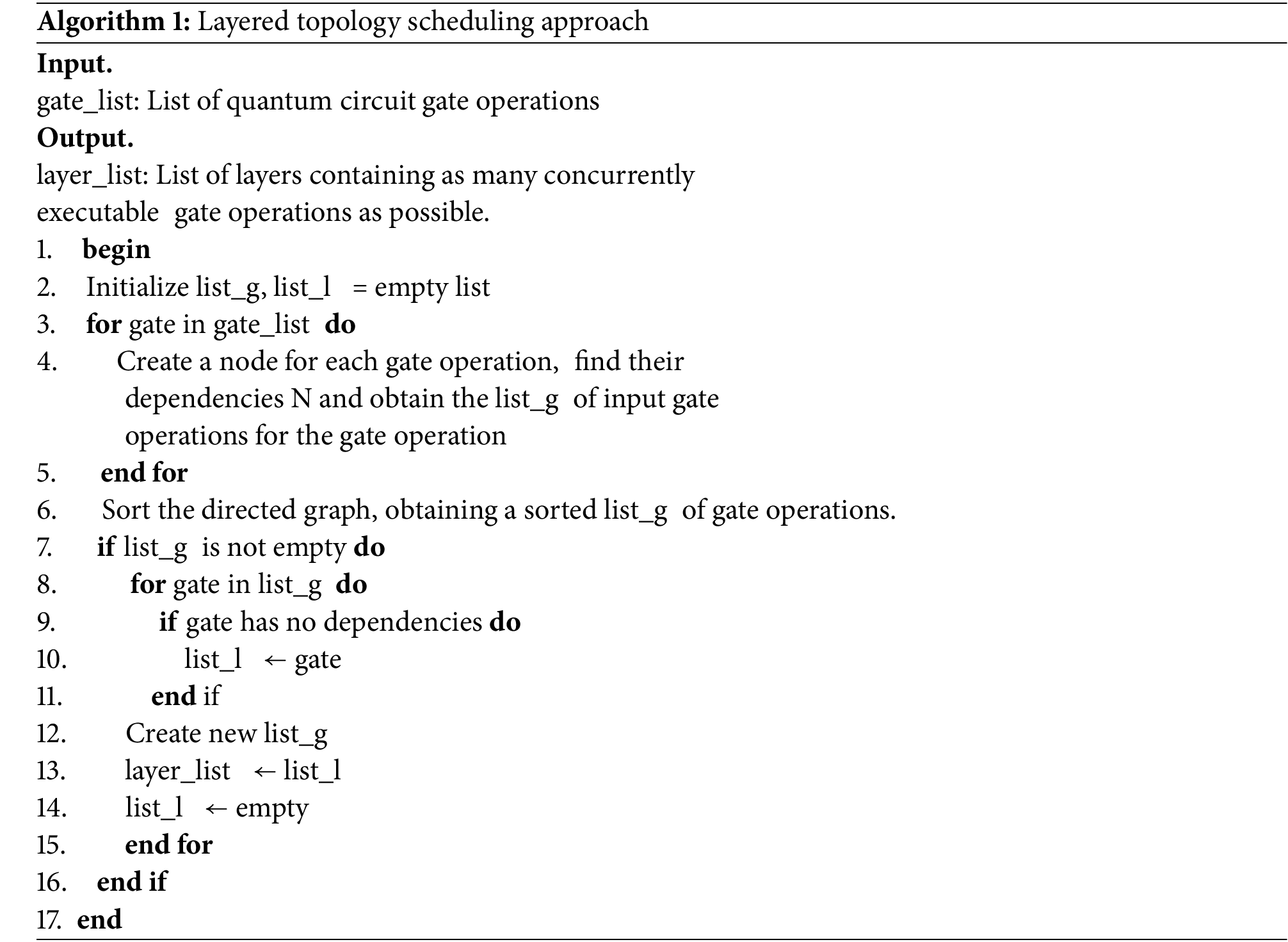
4.2 Layered Topology Scheduling Approach (LTSA)
The quantum gate scheduling problem can be defined as an optimization problem where the decision variables include the order and arrangement of gates in a quantum circuit, structured to respect the dependencies among them; the constraints cover quantum gate dependencies and physical limitations on the hardware; and the optimization objective is to improve the algorithm’s efficiency and performance by maximizing the number of quantum gate operations executed in parallel while ensuring that gate operations without interdependencies are partitioned into time windows that can be executed simultaneously.
The topological level scheduling strategy adopts a greedy algorithm based on heuristic rules, which incorporates the principle of parallelization of gate operations and dependencies in quantum computing, as well as the principle of topological ordering (Definition 3). The LTSA assigns the gate operations to different layers based on the logical order and uses topological ordering to ensure that gate operations in the same hierarchical structure with no interdependencies have priority for execution, thus maximizing the number of gate operations executed in parallel. While Algorithm 1 aims to achieve an optimal distribution of binary operations across layers, its performance may be influenced by the initial ordering of the gate operations provided. The results from Algorithm 1 serve as the input for the subsequent LCRA, which further refines the scheduling based on any remaining conflicts.
Definition 3 Topological ordering: Let G be a directed graph. In this context, a trap node of any directed edge in G is defined as a linear operation that must be executed after the source node of that edge in the ordering. This ensures that the scheduling respects the dependency relationships between operations.
Additionally, it is important to clarify that any binary quantum gate can only operate on connected physical qubits, and two quantum gates cannot operate on the same qubit simultaneously. This guarantees that the topological ordering aligns with the operational constraints of the physical quantum system. For example, if a quantum gate A must precede a quantum gate B in execution, B can be considered a trap node for the edge connecting A to B, indicating that the execution of A is a prerequisite for B.
Theorem 1 In a quantum circuit, the dependency N(qi, qj) of a gate operation in a directed graph GQ constructed based on the connectivity between gate operations is equal to the number of input connections I(qi, qj) of that gate operation node.
where (qi, qj) denotes the corresponding gate operation node and m is a constant.
It is easy to see from the operational characteristics of quantum circuits that the gate operation of an input connection must be executed before the current gate operation; whereas the output connection denotes a subsequent operation that depends on the current gate operation.
When dealing with random sequences of quantum gates for any given problem, the quantum circuit hierarchy construction optimization process is as follows:
Step 1. Initialization: establish dependency graph between quantum gates according to Eq. (3). Calculate the size of the dependency of each quantum gate according to Eq. (3).
Step 2. Construct Layer L1: Traverse the dependency graph and look for nodes (quantum gates) with N(qi, qj) = 0. Putting these nodes into the first layer (L1) indicates that these quantum gates can be executed in parallel.
Step 3. Update dependencies: mark nodes that have been placed into L1 as completed and remove their output edges.
Step 4. Build all layers: loop step 2 and step 3 to build the L2 layer, loop step 2 and step 3 again to build the L3 layer, until all quantum gates have been added to the layer sequence.
The LTSA pseudo-code is as follows:
The following example depicts the topology level scheduling policy implementation process.
The quantum gates and their dependencies are shown in Fig. 3a. In this example, each quantum gate is represented as a node and the arrow lines indicate the dependencies between the gates. In Fig. 3a, take the node (q5, q7) as an example, there are 2 inputs and 1 output, N(q5, q7) = 2, N(q4, q7) = 0, N(q5, q6) = 0, and N(q2, q5) = 2; it is easy to know that (q4, q7), (q5, q6) is a pre-dependency gate of (q5, q7), and (q5, q7) in turn, is a pre-dependency gate of (q2, q5) (i.e., it needs to execute (q4, q7) prior to execute (q5, q7), (q5, q6) and (q2, q5) can be executed only after (q5, q7) is executed).

Figure 3: Hierarchical heuristic greedy algorithm and its examples (a) Dependencies between quantum gates (b) Layered result
After clarifying the quantum gate dependencies (Fig. 3a), traverse each node to find the nodes with N(qi, qj) = 0 and place these nodes in the L1 layer (Fig. 3a-First Layer Formation), and since N(q1, q2) = 0, N(q4, q7) = 0 and N(q5, q6) = 0, the nodes of (q1, q2), (q4, q7) and (q5, q6) are formed into the L1; the dependency is updated, and the nodes that have been placed in the nodes in the layer are removed. Loop traversal, at this point N(q5, q7) = 0 and N(q4, q6) = 0, so (q5, q7) and (q4, q6) form L2 layer. Similarly, (q3, q4) and (q2, q5) form L3 layer. The only remaining node (q1, q3) constitutes the L4 layer. The optimization process of quantum circuit hierarchy construction is shown in Fig. 3a and the layering result is shown in Fig. 3b.
4.3 Layerwise Conflict Resolution Approach (LCRA)
LCRA takes into account the characteristics of quantum computing hardware and the interactions between gate operations, firstly, by prioritizing the execution of Nearest-Neighbor (NN) gates, which include two-qubit gates (like CNOT gates) that can act on qubits that are immediate neighbors, in order to reduce conflicts between adjacent gates. Subsequently, SWAP gates are introduced and ensured to be conflict-free with the near-neighbor gates, which can be executed in parallel in the same cycle, effectively reducing the total execution time. Finally, non-NN gates are executed to make full use of the hardware features and optimize the overall computational efficiency through the ordered execution of gate operations. This scheduling strategy is based on the correlation of neighboring gates, the role of SWAP gates, and the smaller interactions of non-NN gates, which provides a theoretical basis for the orderly execution of gate operations in quantum computing.
The primary objective of LCRA is to consider the characteristics of quantum computing hardware and the interactions between gate operations. By strategically arranging the execution order of gates, it aims to reduce conflicts and enhance parallelism, thereby optimizing overall computational efficiency. The following steps provide a more detailed elaboration of the algorithm along with illustrative examples:
Step 1: Identify Directly Executable Gates: Identify the set of quantum gates that can be executed directly, constituting the first batch of gates for the current layer. Specifically, for each gate in the input gate list of the current layer (map_insts), check if it is a Nearest-Neighbor (NN) gate. If it is an NN gate, mark it as ready for direct execution (schedule = True), remove it from the map_insts list, and add it to the gate list for the current cycle (cycle_insts).
Step 2: Introduce SWAP Gates For quantum gates that cannot be executed directly, introduce the necessary SWAP gates to resolve conflicts and perform batch executions based on conflict situations. Specifically, for gates in map_insts that are not in the directly executable set, check for conflicts with gates in cycle_insts. If there are no conflicts with gates in cycle_insts, set their schedule to True, remove them from map_insts, and add them to cycle_insts.
If a conflict exists—taking CNOT (q0, q5) as an example, which has a qubit conflict with other gates—introduce a SWAP gate (e.g., SWAP (q1, q5)) to adjust the positions of the qubits, allowing for conflict-free execution. Similarly, for CNOT (q5, q14), introduce SWAP (q13, q14). Here, SWAP (q1, q5) and SWAP (q14, q13) do not conflict with certain gates in the first batch (e.g., CNOT (q2, q3)) and can be added to it; however, for CNOT (q1, q4), since the required SWAP (q6, q10) conflicts with H(q10) in the first batch, SWAP (q6, q10) must be added to the second batch. Careful consideration of the conflict relationships between each gate and the connectivity of qubits is essential; for each gate that does not meet the criteria for direct execution, SWAP gates should be introduced thoughtfully to resolve conflicts, ensuring accurate allocation based on conflict situations and hardware architecture characteristics.
Step 3: Merge Results into New Batch: Merge the results from the direct execution phase and the SWAP gate introduction phase to form a new batch and update dependency relationships. Specifically, gates added to cycle_insts in Steps 1 and 2 are treated as the new batch. Simultaneously, update and record the dependency relationships of the introduced SWAP gates with other gates to ensure correct execution.
Step 4: Ensure Full Set Assignment: By repeatedly executing the SWAP gate introduction phase and the new batch formation phase, ensure that all quantum gates are assigned to the appropriate batches. Specifically, continuously repeat the operations of the SWAP gate introduction phase and the new batch formation phase until all gates in map_insts have been added to cycle_insts.
Step 5: Return Optimized Batch List: Return the optimized batch list, where the quantum gates in each batch can be executed in parallel, resulting in an optimized execution order for gate operations within the layer. Specifically, the final output is the cycle_insts list containing all batches, with each batch comprising a set of quantum gates that can be executed in parallel, representing the optimized execution sequence for gate operations within the layer.
The implementation of the intra-layer conflict optimization strategy is illustrated below through an example.
Based on the hardware architecture (as shown in Fig. 4a), it can be determined that the gate operations CNOT (q2, q3); H(q7); CNOT (q8, q9); H(q10); and CNOT (q11, q12) meet the criteria for direct execution. These gates are marked as executable (schedule = True) and are removed from the input gate list, map_insts, and added to the current cycle’s gate list, cycle_insts, as the first batch for execution. For the gates CNOT (q0, q5); CNOT (q1, q4); and CNOT (q5, q14), which do not meet the direct execution criteria, SWAP gates need to be introduced to resolve conflicts. For example, CNOT (q0, q5) has a qubit conflict with other gates, and by introducing SWAP (q1, q5), the qubit positions can be adjusted to allow it to execute without conflicts. Similarly, for CNOT (q6, q14), SWAP (q13, q14) is introduced. The SWAP gates SWAP (q1, q5) and SWAP (q14, q13) do not conflict with some gates in the first batch (such as CNOT (q2, q3)), so they can be added to the first batch; however, for CNOT (q1, q4), the required SWAP (q6, q10) conflicts with H(q10) from the first batch, so SWAP (q6, q10) needs to be added to the second batch. The second batch also includes CNOT (q0, q5) and CNOT (q1, q4), which can be executed after the first batch of SWAP gates has been completed. This is because the execution of these gates depends on the adjustments made to the qubit positions by the SWAP gates, and they can only be executed without conflict after the relevant SWAP gate operations are completed.
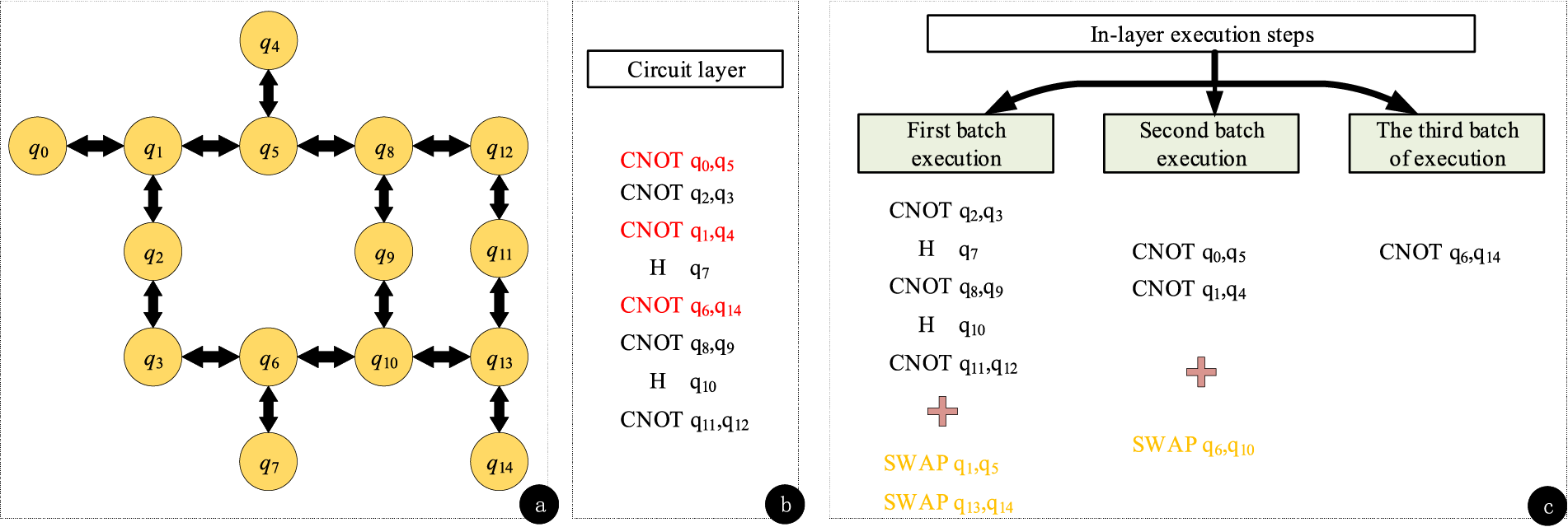
Figure 4: The corresponding hardware architecture and the execution steps of the single-layer quantum gate in the circuit (a) Hardware architecture diagram (b) Problem circuit (c) Execute steps within a single layer
Throughout this process, careful consideration must be given to the conflict relationships between each gate and other gates, as well as the connectivity of the qubits. For every gate that does not meet the criteria for direct execution, conflicts should be resolved by appropriately introducing SWAP gates, and they must be accurately assigned to suitable batches based on the conflict situation and the characteristics of the hardware architecture. This ensures that gate operations within the entire quantum circuit layer can be executed in the optimized order, improving computational efficiency and reducing unnecessary delays and resource consumption.
In this manner, LCRA can fully leverage the characteristics of quantum computing hardware and the interactions between gate operations, effectively addressing the conflict issues of intra-layer gate operations and achieving more efficient quantum circuit scheduling.
In this paper, we use superconducting quantum circuits [17] to implement superconducting quantum models in hardware, which is currently the most promising technology. Currently, the predominant and most mature hardware technology for quantum computing is superconducting qubits. This technology is widely adopted by commercial quantum computing companies and research labs, and a number of important milestones have been achieved. As an example of a quantum hardware model, the IBM Lagos chip information is shown in Fig. 5. Qubits on the chip are located on a planar geometry and are connected by couplers. The couplers are bidirectional arrows indicating that two coupled qubits q can interact. Due to limitations in chip layout and routing, each coupler can only connect one qubit to its neighbor.
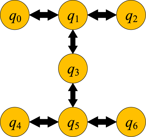
Figure 5: IBM Lagos chip architecture
For example, q1 is connected to q0, q2 and q3 via a coupler This means that a CNOT gate can be applied on the qubit pairs (q0, q1), (q1, q3) and (q1, q2). However, q1 and q5 are not directly connected, and therefore the CNOT gate cannot be applied directly on these two qubits. The benchmarking procedure was selected from IBM’s Quantum program for Qiskit, and for the CX/CNOT gate set, decomposition and optimization were performed using the Qiskit compiler. The benchmarking methodology described in [21] was used to run the mapping process five times and select the best result based on the QAOA model.
Figs. 6 and 7 show the compilation overheads of LTSA, LCRA compared to the t|ket> and Qiskit traditional approaches, respectively; and Fig. 8 shows the overheads of the combination of the two approaches compared to the t|ket> and Qiskit approaches. This paper evaluates the compilation results on an IBM quantum computer equipped with the recommended “FullPass” t|ket> compiler (ver 0.11.0) and the Qiskit compiler (version 0.26.2, optimization level 3), which are limited to CNOT or CZ gate sets.
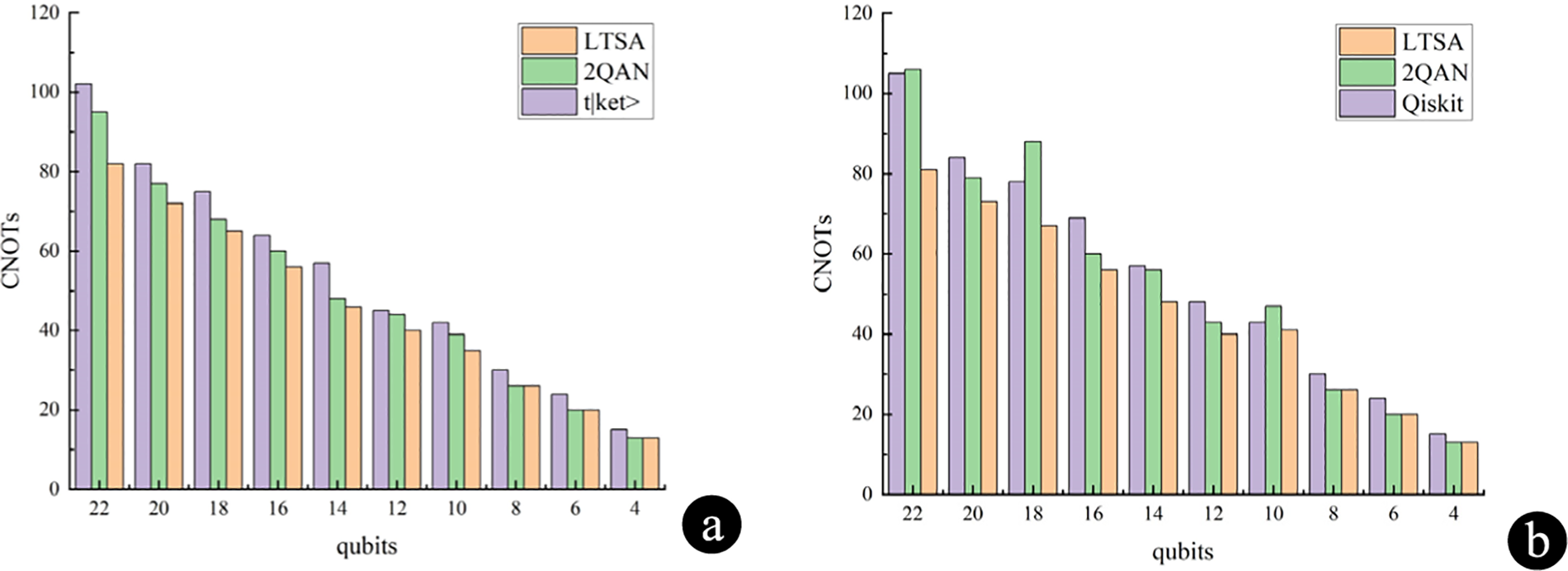
Figure 6: Comparison of LTSA optimization results (a) Comparison of CNOTs compilation costs between LTSA, t|ket>and 2QAN (b) Comparison of CNOTs compilation costs between LTSA, Qiskit and 2QAN
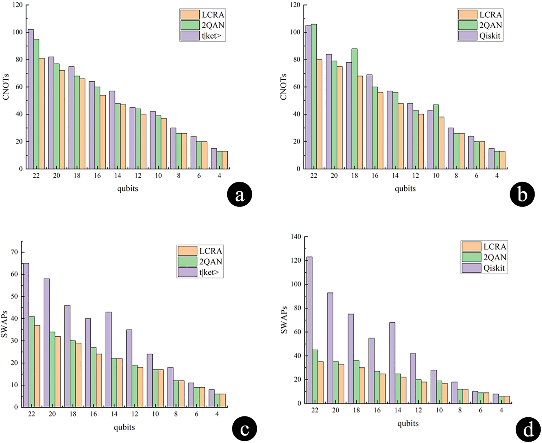
Figure 7: Comparison of LCRA optimization results (a) Comparison of CNOTs compilation costs between LCRA, t|ket>and 2QAN (b) Comparison of CNOTs compilation costs between LCRA, Qiskit and 2QAN (c) Comparison of CNOTs compilation costs between LCRA, t|ket>and 2QAN (d) Comparison of CNOTs compilation costs between LCRA, Qiskit and 2QAN
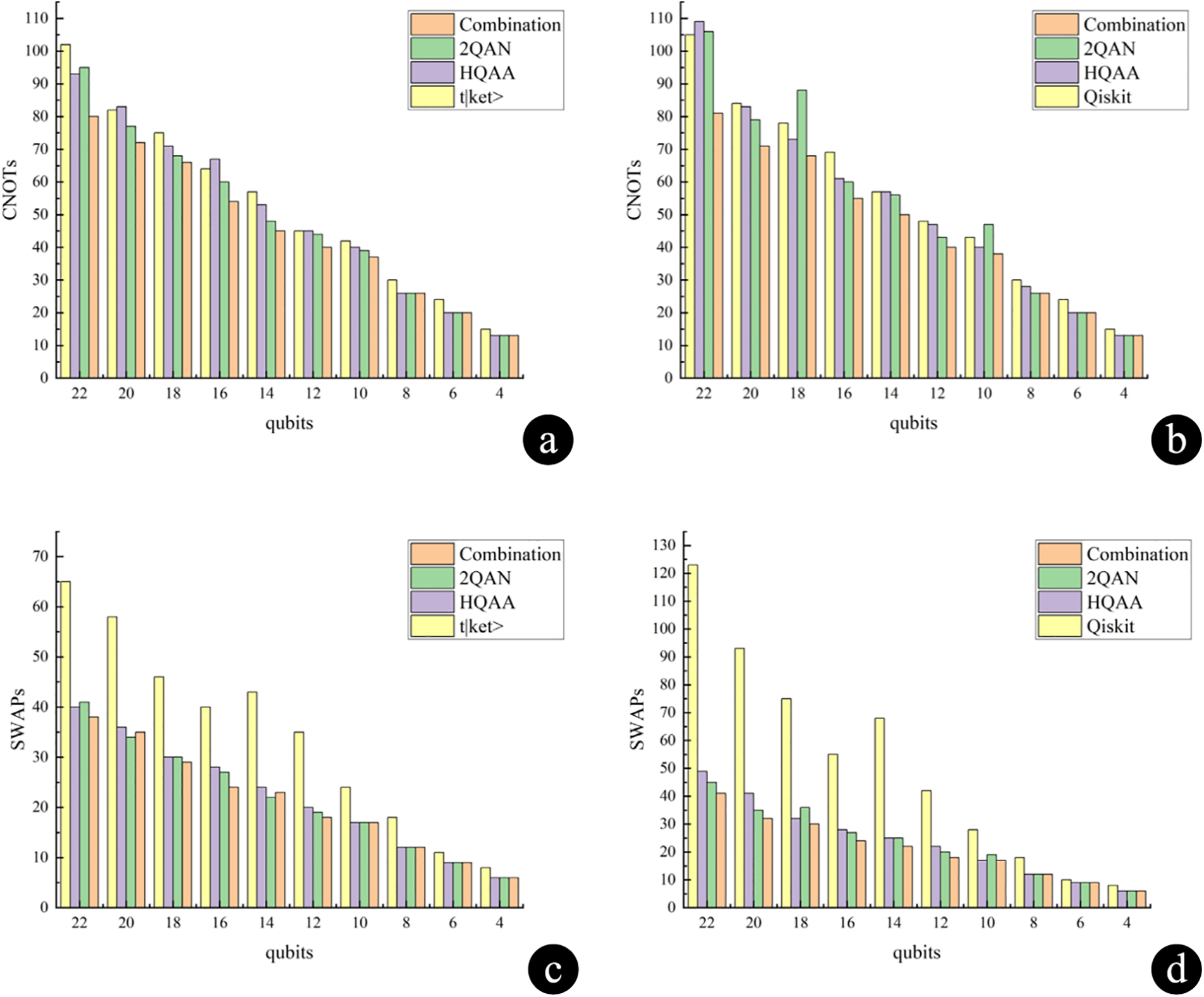
Figure 8: Optimization results of the combination LTSA and LCRA (a) Comparison of CNOTs compilation costs between combination of LTSA and LCRA, t|ket>, HQAA and 2QAN (b) Comparison of CNOTs compilation costs between combination of LTSA and LCRA, Qiskit, HQAA and 2QAN (c) Comparison of SWAPs compilation costs between combination of LTSA and LCRA, t|ket>, HQAA and 2QAN (d) Comparison of SWAPs compilation costs between combination of LTSA and LCRA, Qiskit, HQAA and 2QAN
In this study, we considered the following specific problem instances and conducted detailed experimental evaluations for each instance. For each instance, we provided the best solutions obtained, including execution time and resource consumption, specifically focusing on the number of inserted SWAP gates and the count of CNOT gates in the circuit. These metrics were chosen to facilitate comparison with existing methods, as they directly impact the efficiency and practicality of quantum circuit implementations. By analyzing these factors, we can better assess the performance of our proposed algorithm in real-world scenarios.
After applying the LTSA optimization in the t|ket> compiler, the number of CNOT gates for the case of 4–10 qubits is reduced by an average of 13.8% compared to the original compiler strategy. For the optimization of 12–22 qubits, the number of CNOT gates is reduced by an average of 14.6% compared to the original compiler strategy. In the Qiskit compiler, after applying the LTSA optimization, the number of CNOT gates for 4–10 qubits is reduced by an average of 13.7% compared to the original compiler. For the case of 12–22 qubits, the number of CNOT gates is reduced by an average of 16.4% compared to the original compiler strategy.
The experimental results show that LTSA has the following advantages over the 2QAN scheduling strategy:
1. Parallelism maximization: LTSA uses the topological ordering principle to allocate gate operations in an orderly manner, ensuring that gate operations in the same hierarchy with no interdependencies have priority in execution. This maximizes the number of quantum gate operations executed in parallel and improves the efficiency of the algorithm.
2. Improved hardware resource utilization: By reducing the number of SWAP gates and CNOT gates, LTSA effectively reduces the demand for hardware two-qubit gates and improves the utilization of hardware resources.
3. Wide applicability: based on the principles of parallelization and dependencies, LTSA is suitable for dealing with quantum circuits of different sizes, and significant optimization results have been achieved in both the 4–10 and 12–22 qubit ranges.
Table 1 shows the average runtime comparison between LCRA and 2QAN in compiling the programmes t|ket> and Qiskit. According to Table 1, compiling with LCRA in both t|ket> compiler and Qiskit compiler is effective in reducing the runtime compared to 2QAN.

When LCRA is applied to quantum circuits, in the t|ket> compiler for the case of 4–10 qubits, the number of SWAP gate insertions is reduced by an average of 28.5%, while the number of CNOT gates is reduced by an average of 15%. For the case of 12–22 qubits, after applying the LCRA optimization, the number of SWAP gate insertions is reduced by an average of 43.6%, while the number of CNOT gates is reduced by an average of 14.7%. Correspondingly, in the Qiskit compiler, for the case of 4–10 qubits, the number of SWAP gate insertions after applying the LCRA optimization is reduced by an average of 26.9%, while the number of CNOT gates is reduced by an average of 13.7%. In the case of targeting 12–22 qubits, after applying the LTSA optimization, the number of SWAP gate insertions is reduced by an average of 62.6%, while the number of CNOT gates is reduced by an average of 16.4%.
The experimental results show that compared to the 2QAN scheduling strategy, LCRA reduces conflicts between gate operations by prioritizing the execution of the NN gates before joining the SWAP gate operations, thus improving the parallelism. If there is no conflict between SWAP gates and near-neighbor gates, they can be executed in parallel in the same cycle, which effectively reduces the total execution time. By optimizing the execution order, LCRA can reduce the possible redundant operations or idle cycles, which improves the execution efficiency of the quantum circuit. It also prioritizes the NN gates and SWAP gates to reduce the waiting time for gate operations, thus improving the overall performance of the quantum circuit.
By combining LTSA with LCRA, comparisons were made with the original compiler strategies, 2QAN and HQAA strategies, in both the t|ket> compiler and the Qiskit compiler: Combining the two approaches in this paper for compilation is shown in Fig. 8. For the case of 12–22 qubits, in the t|ket> compiler, compared to the original compiler strategy, the average number of SWAP gate insertions is reduced by 42.2%, and the number of CNOT gates is reduced by 15.6%. Compared to the HQAA strategy, the average number of SWAP gate insertions decreases by 6.6%, and the number of CNOT gates decreases by 13.3%. Compared to the 2QAN strategy, the average number of SWAP gate insertions decreases by 3.2%, and the number of CNOT gates decreases by 8.4%. In the Qiskit compiler, compared to the original compiler strategy, the average number of SWAP gate insertions is reduced by 62.2%, and the number of CNOT gates is reduced by 16.7%. Compared to the HQAA strategy, the average number of SWAP gate insertions decreases by 14.8%, and the number of CNOT gates decreases by 14.0%. Compared to the 2QAN strategy, the average number of SWAP gate insertions decreases by 11.2%, and the number of CNOT gates decreases by 13.7%.
In summary, we are devoted to the development of LTSA and LCRA for the 2-local qubit Hamiltonian simulation problem. LTSA utilizes topological sorting from graph theory and a greedy algorithm to redistribute quantum gates within the layers of the quantum circuit. This maximizes the parallel execution of quantum gates, resulting in a reduction of 49.2% in SWAP count and a 14.5% decrease in hardware gate overhead. On the other hand, LCRA addresses conflicts within layers, optimizing computational efficiency. It achieves a reduction of 52.3% in SWAP count, a 14.8% decrease in hardware gate overhead, and leads to a reduction in circuit compilation runtime. We expect our approaches to play a crucial role in future quantum computing research and applications.
Acknowledgement: None.
Funding Statement: This research was funded by the Natural Science Foundation of Heilongjiang Province (Grant No. LH2022F035), the Cultivation Programme for Young Innovative Talents in Ordinary Higher Education Institutions of Heilongjiang Province (Grant No. UNPYSCT-2020212), and the Cultivation Programme for Young Innovative Talents in Scientific Research of Harbin University of Commerce (Grant No. 2023-KYYWF-0983).
Author Contributions: Study conception and design: Ziao Han, Hui Li, Kai Lu; data collection: Ziao Han, Kai Lu, Shujuan Liu, Mingmei Ju; analysis and interpretation of results: Ziao Han, Kai Lu; draft manuscript preparation: Ziao Han, Kai Lu. All authors reviewed the results and approved the final version of the manuscript.
Availability of Data and Materials: The authors confirm that the data supporting the findings of this study are available within the article.
Ethics Approval: Not applicable.
Conflicts of Interest: The authors declare no conflicts of interest to report regarding the present study.
References
1. Alvarez-Rodriguez U, Sanz M, Lamata L, Solano E. Quantum artificial life in an IBM quantum computer. Sci Rep. 2018;8(1):14793. doi:10.1038/s41598-018-33125-3. [Google Scholar] [PubMed] [CrossRef]
2. Motta M, Sun C, Tan ATK, O’Rourke MJ, Ye E, Minnich AJ, et al. Determining eigenstates and thermal states on a quantum computer using quantum imaginary time evolution. Nat Phys. 2020;16(2):205–10. doi:10.1038/s41567-019-0704-4. [Google Scholar] [CrossRef]
3. Gambetta J. IBM’s roadmap for scaling quantum technology. IBM Research Blog. 2020 [cited 2024 Nov 10]. Available from: www.ibm.com. [Google Scholar]
4. Preskill J. Quantum computing in the NISQ era and beyond. Quantum. 2018;2:79. doi:10.22331/q-2018-08-06-79. [Google Scholar] [CrossRef]
5. Xu J, Chen X, Zhang R, Xiao H. Purification in entanglement distribution with deep quantum neural network. Chin Physics B. 2022;31(8):080304. doi:10.1088/1674-1056/ac6330. [Google Scholar] [CrossRef]
6. Campagne-Ibarcq P, Eickbusch A, Touzard S, Zalys-Geller E, Frattini NE, Sivak VV, et al. Quantum error correction of a qubit encoded in grid states of an oscillator. Nature. 2020;584(7821):368–72. doi:10.1038/s41586-020-2603-3. [Google Scholar] [PubMed] [CrossRef]
7. Alam M, Ash-Saki A, Ghosh S. Circuit compilation methodologies for quantum approximate optimization algorithm. In: 2020 53rd Annual IEEE/ACM International Symposium on Microarchitecture (MICRO) 2020 Oct; Athens, Greece: IEEE. p. 215–28. [Google Scholar]
8. Alam M, Ash-Saki A, Ghosh S. An efficient circuit compilation flow for quantum approximate optimization algorithm. In: 2020 57th ACM/IEEE Design Automation Conference (DAC). 2020 Jul; San Francisco, CA, USA: IEEE. p. 1–6. [Google Scholar]
9. Guerreschi GG, Park J. Two-step approach to scheduling quantum circuits. Quant Sci Technol. 2018;3(4):045003. doi:10.1088/2058-9565/aacf0b. [Google Scholar] [CrossRef]
10. Lao L, Van Someren H, Ashraf I, Almudever CG. Timing and resource-aware mapping of quantum circuits to superconducting processors. IEEE Trans Comput Aided Des Integr Circuits Syst. 2021;41(2):359–71. doi:10.1109/TCAD.2021.3057583. [Google Scholar] [CrossRef]
11. Li S, Nguyen KD, Clare Z, Feng Y. Single-qubit gates matter for optimising quantum circuit depth in qubit mapping. In: 2023 IEEE/ACM International Conference on Computer Aided Design (ICCAD). 2023 Oct; San Francisco, CA, USA: IEEE. p. 1–9. [Google Scholar]
12. Li G, Ding Y, Xie Y. Tackling the qubit mapping problem for NISQ-era quantum devices. In: Proceedings of the Twenty-Fourth International Conference on Architectural Support for Programming Languages and Operating Systems; 2019 Apr. p. 1001–14. [Google Scholar]
13. Li S, Zhou X, Feng Y. Qubit mapping based on subgraph isomorphism and filtered depth-limited search. IEEE Trans Comput. 2020;70(11):1777–88. doi:10.1109/TC.2020.3023247. [Google Scholar] [CrossRef]
14. Zhou X, Li S, Feng Y. Quantum circuit transformation based on simulated annealing and heuristic search. IEEE Trans Comput Aided Des Integr Circuits Syst. 2020;39(12):4683–94. doi:10.1109/TCAD.2020.2969647. [Google Scholar] [CrossRef]
15. Steinberg MA, Feld S, Almudever CG, Marthaler M, Reiner J-M. Topological-graph dependencies and scaling properties of a heuristic qubit-assignment algorithm. IEEE Transact Quant Eng. 2022;3:3101114. doi:10.1109/TQE.2022.3160015. [Google Scholar] [CrossRef]
16. Cross A. The IBM Q experience and QISKit open-source quantum computing software. In: APS March Meeting Abstracts; 2018. [Google Scholar]
17. Yu XM, Deng X, Xu JW, Zheng W, Lan D, Zhao J, et al. Demonstrate chiral spin currents with nontrivial interactions in superconducting quantum circuit. Chin Phys B. 2023;32(4):47104. doi:10.1088/1674-1056/acac17. [Google Scholar] [CrossRef]
18. Nielsen MA, Chuang IL. Quantum computation and quantum information. Cambridge University Press; 2010. [Google Scholar]
19. Fu X, Rol MA, Bultink CC, Van Someren J, Khammassi N, Ashraf I, et al. An experimental microarchitecture for a superconducting quantum processor. In: Proceedings of the 50th Annual IEEE/ACM International Symposium on Microarchitecture; 2017. p. 813–25. [Google Scholar]
20. Zulehner A, Paler A, Wille R. An efficient methodology for mapping quantum circuits to the IBM QX architectures. IEEE Trans Comput-Aided Des Integr Circuits Syst. 2018;38(7):1226–36. doi:10.1109/TCAD.2018.2846658. [Google Scholar] [CrossRef]
21. Lao L, Browne DE. 2QAN: a quantum compiler for 2-local qubit hamiltonian simulation algorithms. In: Proceedings of the 49th Annual International Symposium on Computer Architecture; 2022 Jun. p. 351–65. [Google Scholar]
22. Baioletti M, Rasconi R, Oddi A. A novel ant colony optimization strategy for the quantum circuit compilation problem. In: Evolutionary Computation in Combinatorial Optimization: 21st European Conference, EvoCOP 2021; 2021. [Google Scholar]
23. Arufe L, González MA, Oddi A, Rasconi R, Varela R. Quantum circuit compilation by genetic algorithm for quantum approximate optimization algorithm applied to MaxCut problem. Swarm Evol Comput. 2022;69(7):101030. doi:10.1016/j.swevo.2022.101030. [Google Scholar] [CrossRef]
Cite This Article
 Copyright © 2025 The Author(s). Published by Tech Science Press.
This work is licensed under a Creative Commons Attribution 4.0 International License , which permits unrestricted use, distribution, and reproduction in any medium, provided the original work is properly cited.
 Downloads
 Citation Tools