
 Submit a Paper
 Propose a Special lssue
 Open Access
ARTICLE
Hybrid Framework for Structural Analysis: Integrating Topology Optimization, Adjacent Element Temperature-Driven Pre-Stress, and Greedy Algorithms
1 Department of Mechanical Engineering, Faculty of Engineering, Haliç University, Istanbul, 34060, Türkiye
2 Department of Mechanical Engineering, Faculty of Engineering & Natural Sciences, Bursa Technical University, Bursa, 16330, Türkiye
* Corresponding Authors: Ahmet H. Ertas. Email: ,
Computers, Materials & Continua 2025, 84(1), 243-264. https://doi.org/10.32604/cmc.2025.066086
Received 29 March 2025; Accepted 13 May 2025; Issue published 09 June 2025
 View Full Text
 Download PDF
Abstract
This study presents a novel hybrid topology optimization and mold design framework that integrates process fitting, runner system optimization, and structural analysis to significantly enhance the performance of injection-molded parts. At its core, the framework employs a greedy algorithm that generates runner systems based on adjacency and shortest path principles, leading to improvements in both mechanical strength and material efficiency. The design optimization is validated through a series of rigorous experimental tests, including three-point bending and torsion tests performed on key-socket frames, ensuring that the optimized designs meet practical performance requirements. A critical innovation of the framework is the development of the Adjacent Element Temperature-Driven Prestress Algorithm (AETDPA), which refines the prediction of mechanical failure and strength fitting. This algorithm has been shown to deliver mesh-independent accuracy, thereby enhancing the reliability of simulation results across various design iterations. The framework’s adaptability is further demonstrated by its ability to adjust optimization methods based on the unique geometry of each part, thus accelerating the overall design process while ensuring structural integrity. In addition to its immediate applications in injection molding, the study explores the potential extension of this framework to metal additive manufacturing, opening new avenues for its use in advanced manufacturing technologies. Numerical simulations, including finite element analysis, support the experimental findings and confirm that the optimized designs provide a balanced combination of strength, durability, and efficiency. Furthermore, the integration challenges with existing injection molding practices are addressed, underscoring the framework’s scalability and industrial relevance. Overall, this hybrid topology optimization framework offers a computationally efficient and robust solution for advanced manufacturing applications, promising significant improvements in design efficiency, cost-effectiveness, and product performance. Future work will focus on further enhancing algorithm robustness and exploring additional applications across diverse manufacturing processes.Keywords
Studies on process optimization, runner and gating system design, and process-based topology optimization form a comprehensive framework for improving mold and part design. Process optimization focuses on refining manufacturing parameters to enhance quality and efficiency, while runner and gating system design aims to optimize material flow and minimize defects. Process-based topology optimization integrates structural performance enhancements with manufacturing constraints. By examining these areas, a systematic evaluation of key parameters and challenges enables more effective design solutions.
1.1 Process Optimization: Plastic Injection Molding
Research on process optimization in injection molding focuses on determining optimal manufacturing parameters to enhance product quality, efficiency, and reduce defects. Zhao et al. [1] integrated fast strip analysis (FSA) with particle swarm optimization (PSO) to optimize process parameters, significantly reducing computational costs while maintaining high accuracy in predicting filling behavior. Building on this, Feng et al. [2] developed a two-stage multi-objective optimization tool that combined Taguchi methods, ANOVA, artificial neural networks (ANN), and a multi-objective genetic algorithm (MOGA). Their system effectively reduced defects in automobile air conditioning vents, improving efficiency without requiring extensive knowledge of optimization techniques.
To address weld line constraints and warpage, Wu et al. [3] applied a distributed multi-population genetic algorithm (DMPGA), successfully reducing maximum warpage and the scrap rate by over 40%. López et al. [4] focused on complex part geometries using Design of Experiments (DOE) methods, revealing how localized cooling and material flow variations necessitate detailed experimental analysis for optimal process parameters.
Kitayama et al. [5] used sequential approximate optimization (SAO) with a radial basis function (RBF) network to optimize weld line temperature and clamping force. Their results demonstrated the superiority of 3D cooling channels over straight-type designs in reducing defects. Yang et al. [6] advanced real-time defect detection by integrating digital image processing (DIP) with model-free optimization (MFO), effectively reducing shrinkage and other surface defects.
Focusing on packaging applications, Chen et al. [7] optimized warpage in polyethylene terephthalate (PET) preforms by identifying ambient temperature (42.116%) and melting temperature (41.278%) as the most influential parameters. Their process optimization reduced warpage by 7.72% and lowered rejection rates by 4%. Zhao et al. [8] developed a support vector classifier (SVC) combined with PSO for weight classification, achieving a 0.0212% error with minimal experimental data, demonstrating an efficient and cost-effective optimization strategy for weight control in molded products
1.2 Runner and Gating System Design
Optimization of the runner and gating system is essential for improving material flow, minimizing defects, and optimizing filling patterns. Zhai et al. [9] introduced a multi-objective genetic algorithm to optimize runner diameters, gate locations, and cooling layouts for a balanced trade-off between part quality and manufacturing cost. Their method utilized a Pareto-optimal solution set and a weighted sum approach, proving effective for gate location and cooling layout optimization.
In the context of conformal cooling system design, Li et al. [10] applied topology optimization using boundary element methods (BEM) to improve cooling efficiency and uniformity while ensuring easy integration with CAD (Computer-Aided Design) systems. Feng et al. [11] conducted a comprehensive review, classifying eight cooling layouts and demonstrating a 70% reduction in cycle time compared to conventional systems. Their study emphasized the role of additive manufacturing (AM) techniques, particularly laser powder bed fusion (L-PBF) and epoxy casting, in fabricating high-accuracy cooling molds.
Fu et al. [12] proposed a Voronoi-based level set method for optimizing weld line formation and material distribution by improving injection gate locations. Liu et al. [13] developed a multi-material level set (MMLS) topology optimization method, leveraging fiber orientation distribution to enhance stiffness and achieve a balanced structural design in plastic components. Their simulations demonstrated that weaker materials tend to follow shorter paths to form thick sections, while stronger materials distribute efficiently across the structure for improved mechanical performance.
1.3 Residual Stress: Injection Molded Polymers
Residual stresses in injection-molded polymers directly influence warpage, shrinkage, and overall product quality. Guevara-Morales and Figueroa-López [14] emphasized the need for advanced finite element analysis (FEA) models to account for the varying through-thickness properties of complex geometries. Their research highlighted the importance of integrating experimental data from instrumented molds with FEA simulations to better predict residual stress development in molded parts.
Tang et al. [15] designed an injection mold for producing warpage testing specimens and conducted thermal residual stress analysis using LUSAS Analyst®. Their findings revealed that shrinkage is most significant near cooling channels, leading to uneven cooling and increased warpage. Xie et al. [16] investigated the impact of gate size on flow patterns and residual stresses, showing that undersized gates lead to jetting, slower filling speeds, and increased residual stresses, while appropriately sized gates improve flow stability and reduce stress accumulation.
Glomsaker et al. [17] studied warpage behavior in semicrystalline polyethylene (Linear Low Density Polyethylene), revealing that higher crystallinity levels increase warpage due to uneven solidification during the cooling process. Hassan et al. [18] demonstrated that rectangular cooling channels improve cooling efficiency but necessitate a careful balance between residual stress and shrinkage rate. Qiao [19] proposed a computer-aided optimization method using BEM-based cooling analysis, perturbation-based sensitivity analysis, and a hybrid optimizer combining the Davidon-Fletcher-Powell (DFP) method with simulated annealing (SA) for uniform temperature distribution across the mold cavity.
1.4 Hybrid Topology Optimization Methods
Topology optimization has advanced from simple manual material removal methods [20] to systematic approaches integrating sensitivity analysis, filters, and objective function calculations. Modern research emphasizes hybrid strategies that combine multiple methods for greater efficiency and effectiveness. The ESO-I-PR-PSO method [21] integrates evolutionary structural optimization (ESO) with inverse page rank PSO, where ESO removes excess material and PSO minimizes compliance.
Teimouri et al. [22] utilized bidirectional evolutionary structural optimization (BESO) for lattice generation and material redistribution, while density and level-set methods [23] were used to design functionally graded lattice structures, optimizing both shape and structural performance. Liu et al. [24] enhanced level-set-based optimization using radial basis functions for smoother transitions and boundary interpolation.
Zhou et al. [25] showed that shape and topology optimization without size optimization yields better results, while Bremicker et al. [26] combined computer vision with topology-size-shape optimization for truss and 2D continuum structures [27,28]. Lee [29] introduced a nodal density-based approach combined with shape optimization, a method akin to boundary-based techniques. Lian et al. [30] minimized Von-Mises stress through a combined shape-topology optimization, reducing compliance by up to 33% compared to conventional methods. Nguyen et al. [31] further refined structural optimization by incorporating adaptive mesh coarsening for improved computational efficiency.
Focusing on additive manufacturing, Teke et al. [32] proposed the D-S-ER hybrid method, integrating density-based optimization, shape optimization, and element removal. Their approach demonstrated significant improvements across three case studies:
• 167.5% compliance reduction for a cantilever beam
• 27.8% volume reduction for a corbel structure
• A reduction of compliance from 84.34 to 21.397 Nmm in the GE bracket
Teke and Ertas [33] applied this methodology to optimize a lifting hook, effectively reducing maximum stress while maintaining structural integrity. Their 1D submodeling approach [34], validated through beam formulations and 3D printing-based experimental tests, proved efficient for improving fatigue life and ensuring safety compliance under repeated loading conditions.
In addition, Grubits et al. [35] explored topology optimization in the plastic-limit regime by applying BESO to I-beams with various beam-column connection types under nonlinear conditions. Their results demonstrate that optimized configurations can achieve similar structural performance to conventional solid web beams, while saving material and enhancing rotational stiffness across semi-rigid and welded joints.
Expanding the discussion to uncertainty modeling, Habashneh et al. [36] introduced a reliability-based topology optimization framework that accounts for stochastic variation in load position and material imperfections. Their BESO-based approach integrates probabilistic constraints (e.g., target reliability index) into the optimization loop, yielding robust structures under geometric and material nonlinearity. They validated their method across multiple benchmark cases including cantilever and shell structures, showing marked shifts in optimal topology and stress distribution when uncertainty is explicitly considered.
This study optimizes part and mold design by integrating topology optimization with gating and runner system determination within a structural analysis framework. The goal is to enhance mechanical performance and manufacturability by ensuring efficient material distribution in injection-molded components. For part optimization, density-based topology optimization (TO), shape optimization, and element removal methods refine structural configurations. A submodeling-based approach, incorporating beam formulation in finite elements, enables localized stress analysis while maintaining global optimization. Both standalone methods and hybrid strategies—such as D-S-ER (Density-Shape-Element Removal) and Submodeling-D-S-ER—are explored to maximize design flexibility and improve the strength-to-weight ratio. The gating and runner system is optimized to enhance mechanical performance. A randomized search algorithm identifies optimal ingate locations, while a greedy algorithm combined with the adjacent element method generates an adaptive, efficient runner layout. The Adjacent Element Temperature-Driven Prestress Algorithm (AETDPA) is integrated into the finite element model (FEM) to refine material distribution and thermal behavior, accounting for temperature-dependent material properties and prestress effects. Iterative optimization ensures temperature uniformity, minimizing residual stresses and thermal-induced deformations. A comparative analysis evaluates the optimized design against existing solutions in terms of mechanical strength, weight reduction, manufacturability, and cycle time efficiency. Advanced structural analysis techniques assess stress distribution, ensuring industry performance standards. This study establishes a computationally efficient, automated framework for part and mold optimization, applicable across injection molding and advanced manufacturing. By integrating topology optimization, gating and runner system determination, and AETDPA, the methodology enhances structural integrity, manufacturing efficiency, and product reliability for complex engineering components.
This study introduces a novel hybrid optimization framework that integrates topology optimization (TO), Adjacent Element Temperature-Driven Pre-Stress Algorithm (AETDPA), and greedy runner system generation algorithms for the structural enhancement of injection-molded parts. The key contributions distinguishing this work from previous studies include:
• The first application of AETDPA within a concurrent mold-part design loop, offering mesh-independent accuracy in stress prediction and failure localization.
• A unique D-S-ER and S-D-S-ER hybrid topology optimization sequence integrating density-based, shape, and element removal techniques within a submodeling environment.
• A greedy algorithm for runner system generation, optimized for manufacturability and mechanical strength, outperforming random or purely global search methods in structured injection paths.
• Experimental validation through bending and torsion tests, directly confirming numerical findings and showcasing the physical performance benefits of the integrated approach.
Compared to previous frameworks, this method streamlines part optimization, enhances manufacturability under thermal-induced prestress, and enables adaptive structural improvements across different mold designs.
The process in Fig. 1 begins with the determination of the AETDPA parameters for both the current part and mold design. These parameters are then applied within the finite element model (FEM) to account for thermal expansion, ensuring accurate displacement calculations.
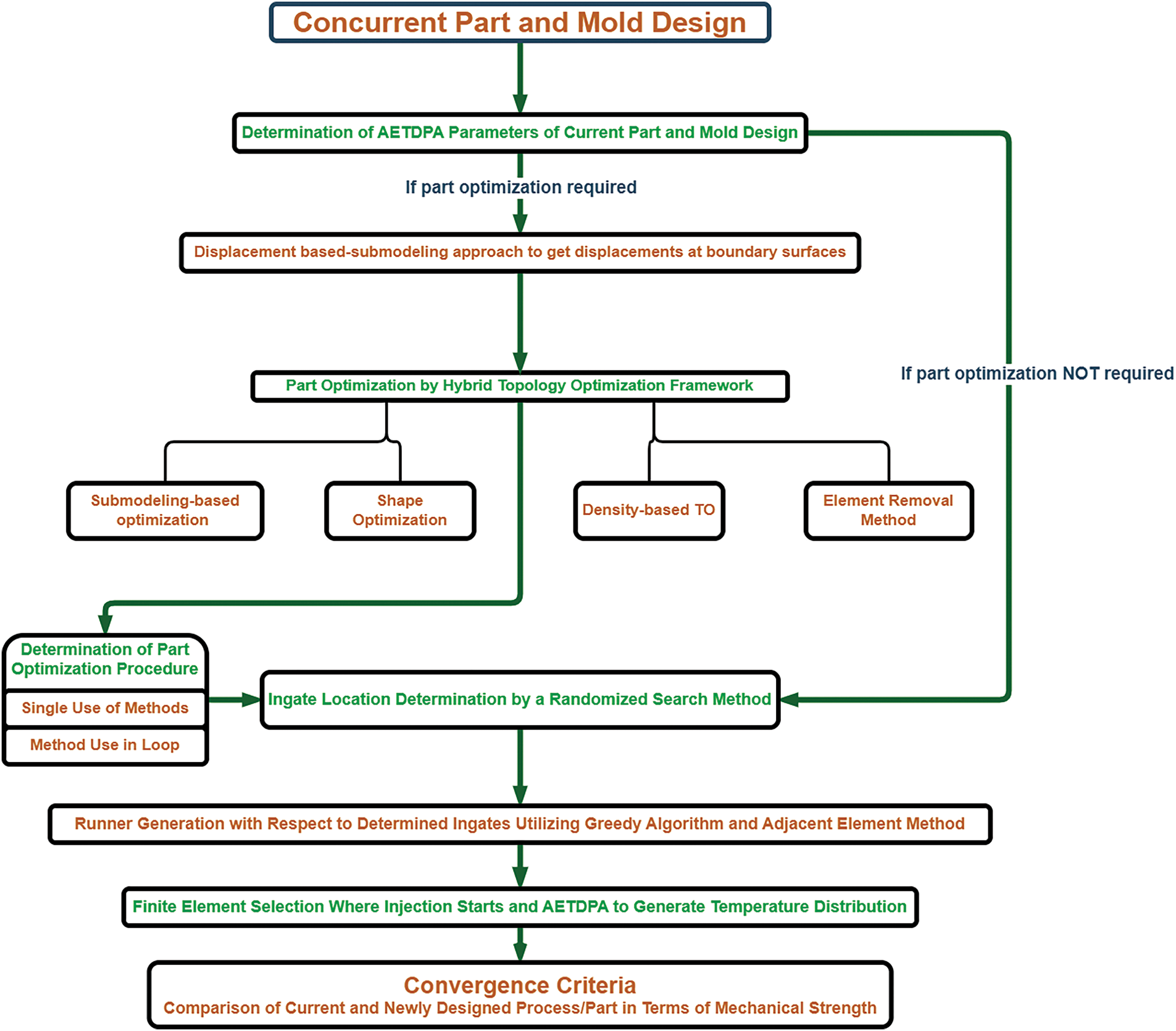
Figure 1: Hybrid framework for part and mold design
A displacement-based submodeling approach is used to extract displacements at the boundary surfaces, which will later be incorporated into the optimization framework.
If part optimization is required, the procedure follows a hybrid topology optimization framework, integrating different methods to refine the part design. First, a submodeling-based optimization approach utilizing beam formulation on finite elements is employed.
Then, additional topology optimization methods such as element removal, density-based topology optimization (TO), and shape optimization are applied to refine the structure. The final part optimization procedure is determined based on these techniques, which can be executed individually (submodeling-based optimization, density-based TO, shape optimization, or element removal) or in a loop using a D-S-ER sequence (Density-based TO, Shape Optimization, and Element Removal) or a Submodeling-D-S-ER sequence (Submodeling-based Optimization followed by Density-based TO, Shape Optimization, and Element Removal).
Once the part optimization is completed, or if part optimization is not required, the ingate location determination is conducted using a randomized search method. The next step involves the application of thermal expansion in the finite element model, using the previously determined AETDPA parameters. Based on the identified ingates, a runner system is generated utilizing a greedy algorithm combined with the adjacent element method. The finite element selection process then determines the specific elements where the injection starts, and AETDPA is used to generate the temperature distribution across the part.
Finally, after the new part design is finalized, the thermal expansion application is repeated using the same AETDPA parameters in the FEM. A comparison is then conducted between the current and newly designed parts, focusing on mechanical strength which is based on numerical three-point bending analysis. This evaluation ensures that the new design maintains or improves upon the structural integrity of the original part while optimizing manufacturability and performance. Maximum deflection and potential fracture point are the measures for the mechanical performance. Thus, decrease in material usage reduces cost and makes it a more suitable choice for the manufacturer. Main objectives for the optimization procedure are reduction of mass and preserving or increasing mechanical strength.
2.1 Thermal Strain Application in Finite Element Method
The Adjacent Element Temperature-Driven Pre-Stress (AETDP) algorithm extends FEA by incorporating thermal strain distributions and residual stresses from manufacturing processes like additive manufacturing and injection molding. By mapping thermal strains onto nodal displacements through shape functions, it enhances stress and strain predictions, offering a more comprehensive depiction of material behavior influenced by geometry and process effects. In FEA, the displacement field within an element is approximated using nodal displacements and shape functions. The global displacement vector D is formed by assembling nodal displacements from all elements. The governing system of equations is expressed as KD = F, where K is the global stiffness matrix, and F is the nodal force vector. For a linear 3D hexahedral element, shape functions are defined accordingly. Thermal displacement results from material expansion or contraction due to temperature changes, given by thermal strain expressions (accordingly stress calculation in FEA model is given in Eq. (1)). For isotropic materials, thermal displacement depends on the position vector in the reference configuration and the temperature change. The total displacement field combines both mechanical and thermal displacements. Incorporating thermal expansion into the constitutive equation modifies the stress-strain relationship based on Young’s modulus and Poisson’s ratio.
Von Mises stress is used to evaluate yielding and failure under complex loading conditions. By integrating AETDP with FEA, failure regions, strength assessments, and fracture orientations can be identified more accurately, improving material behavior predictions under multi-axial stress states. Potential fracture orientations are inferred from Von-Mises stress contours under static loading conditions (Eq. (2)).
Accordingly, assignment of temperatures via AETDP algorithm goes with the explanation given in Fig. 2. This code processes finite element analysis (FEA) data by loading nodal and connectivity information, mapping nodes to elements, and ordering elements using a breadth-first search (BFS). It then assigns temperatures to nodes based on user-defined coolant and maximum temperatures, incorporating a geometric modulus (volume/surface area). The script calculates the average temperature for each element and visualizes the results using a 3D scatter plot with color mapping. This workflow ensures structured element traversal, accurate thermal distribution, and clear visualization of temperature variations in the model.

Figure 2: Explanation diagram of AETDP algorithm
2.2 Ingate and Runner System Design Algorithm
The pseudo-code in Fig. 3 automates the ingate determination process by evaluating mechanical strength using ANSYS® Workbench. It performs a randomized search by selecting different ingate finite elements, loading node and connectivity data, and mapping elements using BFS. Temperatures are assigned based on material properties, and average element temperatures are computed and saved. ANSYS® is then executed in batch mode for mechanical strength analysis, and the best ingate element is identified by evaluating results from multiple iterations.
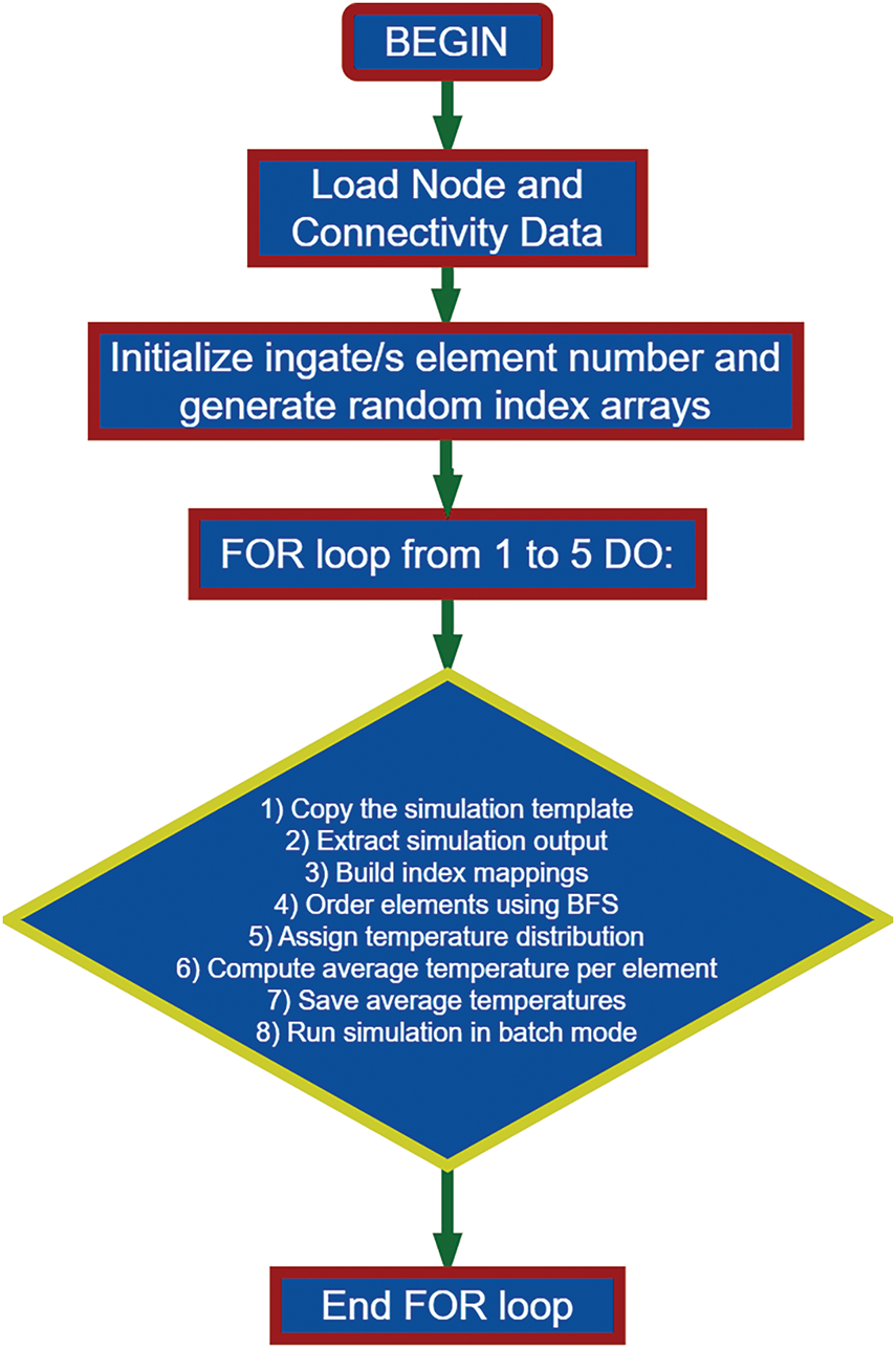
Figure 3: Randomized search for best ingate finite element
The runner system generation pseudo-code in Fig. 4 automates the determination of optimal ingate paths in a finite element mesh, focusing on adjacency constraints and mechanical strength evaluation.

Figure 4: Runner system generation algorithm
Below is an overview of the runner path generation method used in Fig. 4. The algorithm operates using a beam search-inspired strategy, which iteratively expands the search space by evaluating the neighboring elements of each node. At each iteration, a fixed number of adjacent elements with the shortest Euclidean distance to the target are selected and added to the path. This step-by-step expansion continues until a valid path to the injection target is formed. To prevent loops, already-visited elements are excluded from further consideration. The process ensures efficient and manufacturable pathfinding within the finite element mesh.
Elements: Each element is denoted as (for i = 1, 2, … , N) with a centroid (center of mass) given by:
Adjacency: Two elements are considered adjacent if they share at least one common node and the Euclidean distance between their centroids is less than or equal to a given threshold (e.g., max_distance).
Objective: Find a path (or paths) from a starting element s (e.g., ingate1 or ingate2) to a target element t, where at each step, more than one candidate (as specified by a parameter) from the current element’s adjacent nodes is considered for path extension.
Euclidean Distance: The Euclidean distance between the centroids of two elements is computed as:
This formula is used both to check adjacency (
2.2.3 Beam Search Method Theory
Beam search is a heuristic search strategy that limits the search space by retaining only a fixed number of the best candidate paths (the beam width) at each expansion step. In our context:
Initialization to start with a beam that contains a single path:
Path expansion for each candidate path
• Let
• Obtain the set of adjacent elements
• Exclude those adjacent elements that are already in the current path (to prevent cycles).
• For each candidate
• Extend the current path by appending candidate_i to form a new path:
After expanding all candidate paths, sort the new paths based on the heuristic value (i.e., the distance from the new node’s centroid to the target centroid). Retain only the top B paths (where B is the specified beam width or the number of adjacent nodes to be considered, referred here as advance Count).
The search stops when:
• One or more candidate paths have their last element equal to the target t, or
• A maximum number of iterations is reached.
Stopping criterion:
The process begins with loading node and element data, mapping indices, and computing centroids for each element. Using a node-to-elements mapping, adjacent elements are identified based on a 6 mm distance threshold, establishing valid connections for pathfinding. The ingates, intermediate targets, and final target are predefined to ensure structured traversal. A greedy path search is performed separately for ingate1 and ingate2, where the algorithm iteratively selects the nearest adjacent element toward the goal centroid. To prevent loops, cycle detection is implemented, and if no valid path is found, an error message is displayed. Once paths are determined, each element in the path is expanded by incorporating up to six adjacent neighbors or so, ensuring a broader selection of elements for further evaluation. Finally, the script displays the final augmented paths and stops the timer to measure execution efficiency. This structured approach ensures efficient ingate-to-target connectivity while considering mechanical constraints. The results provide a robust basis for further ANSYS® Workbench simulations, allowing for optimized ingate placement and mechanical strength analysis.
2.2.6 Justification for Greedy Algorithm Selection
The choice of a greedy algorithm over alternative search methods such as Dijkstra, A*, or genetic algorithms is motivated by computational efficiency and practical suitability for injection mold design. Since runner paths are constructed within constrained topologies with predefined ingates and targets, a greedy approach ensures fast traversal of adjacent elements, emphasizing the shortest local paths and avoiding cycles. Unlike global search methods, the greedy algorithm enables faster execution suitable for real-time simulation loops and easy integration with AETDPA-based temperature assignments. Its localized nature also allows greater flexibility for iterative manufacturability evaluations.
2.3 A Hybrid Framework: Concurrent Mold and Part Design
The hybrid framework’s working procedure (Fig. 5) is stated as follows:
1. Initial Thermal Strain Application in ANSYS® Workbench: The model is first subjected to thermal strain, establishing a prestressed condition. Under this state, mechanical loads are subsequently applied.
2. Structural Response Transfer via Submodeling: The structural results from the prestressed model are exported to a separate sub-project to determine displacements due to mechanical loading. This process is conducted using submodeling while preserving the integrity of the global model.
3. Topology Optimization for Feasibility: Various topology optimization (TO) methods are evaluated, and the most manufacturable solution is selected. As illustrated in Fig. 5, the single key-socket frame presents the most feasible outcome in terms of production. This design is refined using submodeling-based TO to maintain its marketplace integrity. Conversely, density-based TO and shape optimization techniques produce solutions that are impractical for manufacturing and market considerations. Additionally, the D-S-ER approach results in a freeform structure, making it unsuitable. In contrast, beam formulation-based submodeling TO, applied to finite elements, optimizes weight reduction by minimizing thickness through cross-sectional reduction and element removal. Manufacturability is judged based on: (i) absence of undercuts, (ii) continuous geometry for mold release, (iii) interface flatness for runner joining.
4. Ingate Selection via Algorithmic Approach: A randomized search algorithm is employed to determine the ingates by randomly selecting elements and evaluating their mechanical strength. Thermal expansion is applied at these ingates to identify the optimal configuration. The finalized ingate locations are then used in a greedy algorithm to determine the shortest path to the injection point. The part is enclosed within a box to define the design space for runner system generation. As depicted in Fig. 5, the inclusion of ingates and intermediate elements prevents collisions between the part and the runner, ensuring flexibility for various runner system configurations.
5. Final Mechanical Strength Verification: The mechanical strength of the system is reassessed after thermal expansion is applied. Each modification in part geometry, runner system, or ingate selection alters the temperature distribution across elements, impacting mechanical strength. However, if the part topology remains relatively unchanged, the same thermal expansion conditions can be reliably applied despite variations in mechanical loading. This will be further explored in the subsequent sections. Runner redesign was informed by bending stiffness criteria. While torsional response remained unchanged, enhanced bending performance justified their inclusion.

Figure 5: Hybrid framework flow chart
2.4 Topology Optimization Problem Definition
The 1D-submodeling code is developed to simulate the deformation behavior of a structurally optimized, injection-molded component under load, where regional stiffness calculations are used to adaptively resize the geometry. Additionally, the framework allows for design improvements that align with both strength and manufacturability criteria. It integrates computational mechanics, automated FEM simulation, optimization, geometric definition, and mesh visualization steps. Originally utilized to introduce internal voids within thick components during initial geometry formation, this method has been adapted for thin parts—such as the key-socket frame—by modifying wall thickness in specific regions to preserve structural strength while achieving mass reduction. From a manufacturability standpoint, it is important to note that the current design is already being produced and is part of a commercial product. Therefore, the scope of allowable modifications is inherently limited. Moreover, to ensure compatibility with the existing socket and key mechanisms, only minimal and localized adjustments were deemed appropriate within the optimization process.
The topology optimization approach employed in this study includes a local section-wise flexural optimization routine based on beam bending theory and nonlinear shape parameterization. The method targets structural efficiency under bending by minimizing deflection caused by moment loads applied along the span. The optimization is governed by the following parameter definitions:
• Target Volume Constraint: The total cross-sectional area is distributed across n = 8n = 8n = 8 segments along the beam length. Each segment is optimized individually with volume constraints implicitly controlled by the integration of the moment and inertia relationship “
• Penalization Scheme: Although not SIMP (Solid Isotropic Material with Penalization)-based, a geometric penalization is embedded through nonlinear shape-to-area mapping: the optimized parameter is transformed as Ai = 0.8⋅(ni·12)1/4, which mimics penalized stiffness control.
• Filtering: No explicit density filtering is applied as the optimization operates on isolated segments, however, a symmetry condition and mirrored constraints are enforced to maintain structural continuity and avoid checkerboarding.
• Update Strategy: A nonlinear minimization function based on bending energy is applied:
where ki is a curvature coefficient. Optimization is performed via MATLAB’s fmincon function with bounds and linear inequality constraints.
• Convergence Criteria: Iterative optimization stops once segmental stiffness converges to within 1% tolerance across two successive iterations. For each segment, the number of iterations ranges between 15–25.
• Mesh Resolution and Influence: The method operates on a mesh generated via Gmsh, using face-normal-directed extrusions. Mesh sensitivity is addressed by fixing the number of longitudinal segments (n = 8) and controlling lateral face placement through extracted nodes on min/max planes. Resulting geometry is automatically re-fed into the thermal simulation loop for mechanical assessment.
Overall, this segment-wise optimization mimics a topology-shape hybrid method where moment-induced stresses dictate shape growth, and prestressed FE (Finite Element) verification confirms structural feasibility.
3 Experiments on Mechanical Strength and Numerical Comparison
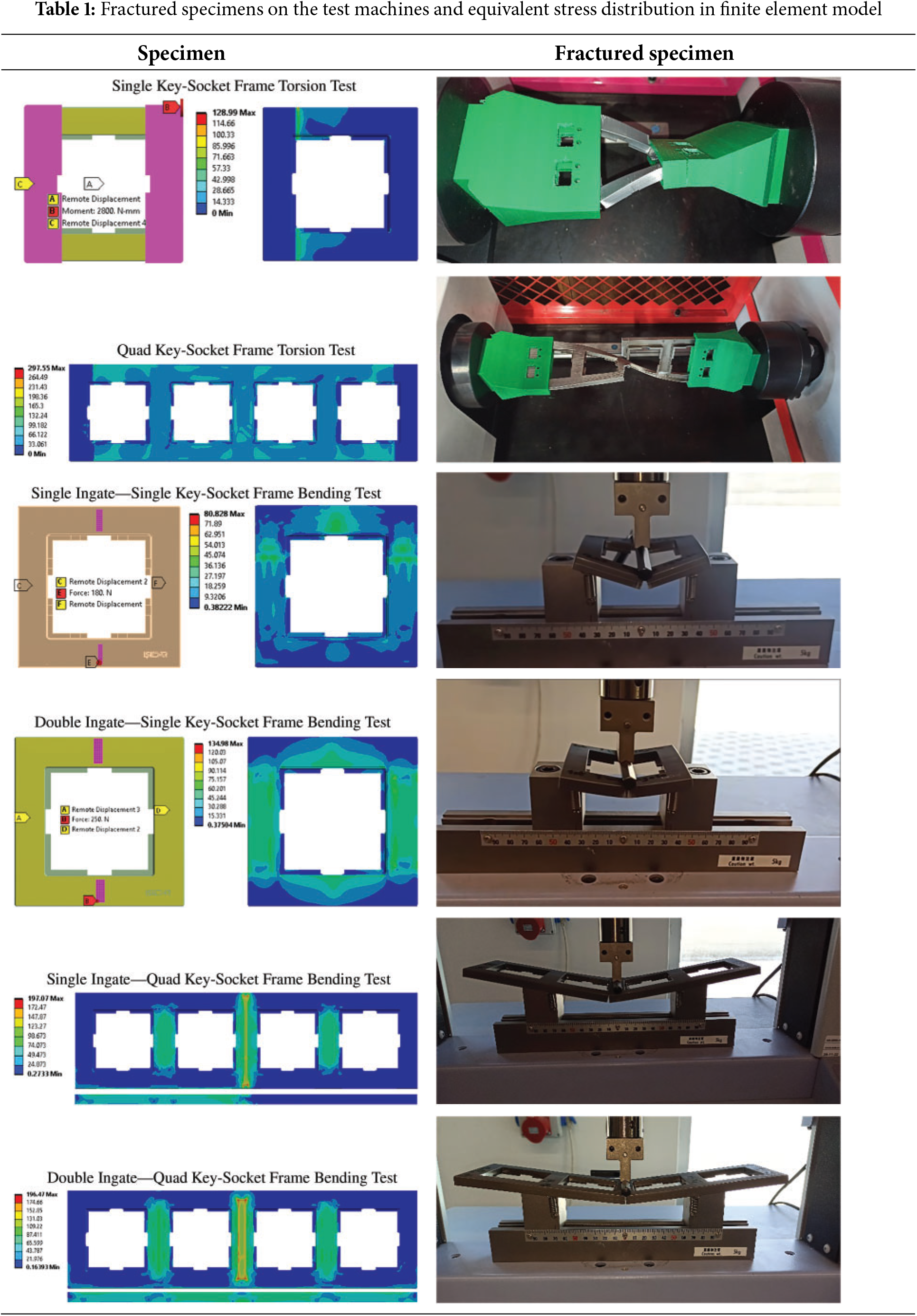
The experimental setup for torsion and bending tests applied to single and quad frames, along with the images of fractured specimens and the equivalent stress distributions, is presented in Table 1. Equivalent stress distributions correspond to the final simulation state prior to fracture initiation. In the torsion test conducted on the single frame, fractures occurred at the expected points, specifically at the locations where the apparatus gripped the specimen. It was observed that the fracture took place at the fixed section of the testing machine. This observation was further confirmed by the numerical analysis, which revealed that the stress concentration was also localized in that specific area.
Testing equipment and procedure are as follows:
• Equipment: Shimadzu testing machine with a 1 kN load cell.
• Sample Preparation: ABS (Acrylonitrile butadiene styrene) injection-molded parts were fabricated using a precision steel mold. Each configuration (single vs. quad; single vs. double ingate) included three samples.
• Boundary Conditions:
• Torsion Test: Fixed at one end, torque applied at the opposite end.
• Bending Test: Simply supported beam configuration with center-point loading.
• Loading Parameters:
• Displacement-controlled loading at 10 mm/min.
• Failure Assessment:
• Visual fracture detection.
• Stress-strain curves analyzed to identify yield and fracture points.
• Post-Processing:
• Stress localization correlated with FE-predicted Von-Mises distribution.
In contrast, for the quad frame under torsion testing, the stress appeared to be almost uniformly distributed across the entire structure. However, in other tests, including both single-runner and double-runner configurations, the fractures consistently occurred in the same regions regardless of the system used. The primary distinction between single-runner and double-runner systems for both the single and quad frames became evident primarily in the bending tests.
For the single-runner single frame, when analyzing the stress distribution during the bending tests, it was observed that high-stress concentrations occurred only on one side of the loading region. On the other hand, in the double-runner single frame, the stress distribution was more homogeneous across the structure. The fracture patterns for these parts during the tests are also displayed in Table 1.
In single-runner quad frames, the bending tests revealed that the initiation of fractures occurred slightly towards the left from the loading center. The numerical analysis results of the equivalent stress distribution confirmed that the stress concentration was focused in the same region. In contrast, for the double-runner quad frame, fractures took place directly at the center of the loading area, and the stress distribution demonstrated a significant level of symmetry between the left and right sides of the frame.
The numerical results mentioned above were obtained using the Adjacent Element Temperature-Driven Prestress Algorithm (AETDPA). This algorithm allowed the stress regions, where fractures were observed experimentally, to be effectively replicated within the finite element model. The finite element model was developed using the ANSYS® software, and the parameters used in the model are presented in Table 2.
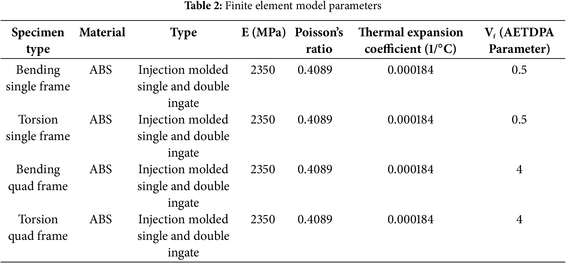
The parameters, including the Young’s modulus (E), Poisson’s ratio, and the thermal expansion coefficient, were utilized in an isotropic elastic material model, which represents the standard structural analysis parameters. The parameter referred to as Vf denotes a cooling factor related to the mold filling and subsequent cooling process. This parameter represents the gradual cooling of elements assigned temperature values and simulates the cooling cycle the material undergoes after the molding process. By creating a temperature distribution, a pre-stress condition is established, which enhances the default capability of the mechanical failure detection in the simulation.
A critical point to note in Table 2 is that, even though different runner systems were used for the same parts, the Vf parameter remained constant across all configurations. This consistency ensured that mechanical simulations were performed under identical conditions and aligned with the experimental results. Additionally, since the geometric module calculations included in the AETDPA supported this approach, it was possible to design different runner systems and still accurately predict part behavior under the same conditions, provided there were no critical geometric changes made to the part.
In Table 3, the experimental results of torsion and bending tests are presented. In addition to the bending tests, newly developed runner systems and their corresponding finite element simulation results for bending are also provided. The new designs were developed primarily based on bending tests, and the results, presented in Table 3b,d, demonstrated significantly stiffer structures compared to the previous configurations. In the torsion tests (Table 3a,c), no significant performance differences were observed between the configurations. However, the bending tests (Table 3b,d) revealed a clear distinction, as the single and double-runner systems in the quad frame exhibited substantially different strength performances. The configurations of the previous and updated runner systems are detailed in Fig. 6.
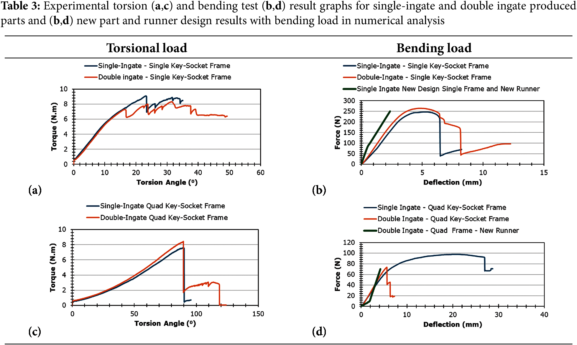

Figure 6: (a) Old runner and single frame, (b) new runner and single frame, (c) old runner and quad frame, (d) quad frame with new runner
It is important to note that the original runner system and part geometry were not theoretical proposals but were in fact previously manufactured and experimentally validated in industrial practice. Therefore, the objective of this study was not to replace an unvalidated system, but rather to evaluate whether an improved structural response could be obtained through a redesign of the runner layout and selective refinement of the part geometry—without violating existing manufacturing constraints. This case study framework allowed us to develop and validate a novel hybrid methodology that incorporates both part optimization and runner system reconfiguration using temperature-induced pre-stress effects derived from a process-fitted baseline. The newly developed runner systems prioritize enhanced bending performance and are evaluated within this hybrid setting, without implying that the original design was deficient, but rather to explore the structural optimization space enabled by AETDPA.
The equivalent stress distributions corresponding to these configurations are illustrated in Fig. 7. The older single frame and runner system exhibited a broader stress distribution compared to the newer design. In the updated design, the stress distribution became more concentrated, resulting in a clearer and more predictable failure zone.

Figure 7: Old and new designs’ equivalent stress distributions
Similarly, in the initial double-runner configuration of the quad frame, there was an advantage of focused fracture initiation around the loading center compared to the single-runner system. With the newly developed runner system, the quad frame exhibited increased stiffness, and the stress distribution clearly highlighted the failure region, making it more distinct and predictable based on the stress concentration patterns observed.
Process fitting provides mechanical failure and strength properties, facilitating the design of new parts and runner systems. This approach enhances both material efficiency and time optimization during mold-part development.
Additionally, process fitting remains applicable when using different runner systems for the same part. These runner systems are generated through a greedy algorithm that relies solely on adjacency and the shortest path. This enables the evaluation of various runner configurations for improved mechanical performance or reduced material usage. The validity of this approach has been confirmed through three-point bending and torsion tests conducted on both single and quad key-socket frames, as detailed in Section 3.
By integrating part optimization with mechanical failure and strength fitting through thermal expansion application (AETDPA which is a prestress algorithm developed for this process), this structural methodology presents new opportunities in topology optimization research. AETDPA has been successfully validated in previous studies for predicting mechanical failure regions and strength in both 3D-printed plastic and injection-molded parts. Furthermore, its potential expansion to metal additive manufacturing could introduce new capabilities for mechanical failure prediction and strength optimization. However, due to the high cost of metal additive manufacturing, its implementation is reserved for future studies.
One of AETDPA’s most significant advantages is its mesh independence, eliminating the need for a highly refined mesh to align with experimental results.
The hybrid topology optimization (TO) framework offers flexibility in selecting the most appropriate optimization method for a given part. The process evaluates the part’s minimum thickness and geometric constraints to determine the most suitable optimization approach. In this study, thin parts were utilized, and the single key-socket frame was optimized through submodeling to achieve localized thickness reductions. Due to its status as a market product, modifications to the design were kept minimal. Additionally, as an improvement, runner systems were developed for both the single and quad key-socket frames.
By introducing new possibilities in both injection molding and additive manufacturing, the hybrid TO and mold design framework can accelerate the runner system design process, enhance mechanical strength predictions, and improve failure region assessments.
The proposed hybrid framework demonstrates strong computational performance in comparison to conventional methods. For example, the greedy algorithm completes runner pathfinding in under 11.8 s on average across 10 trials, while randomized ingate searches complete within 222 s depending on mesh size. The D-S-ER loop converges within 2 or 3 steps for D-S loop (30–35 iterations) and as a final step ERM (Element Removal Method) within 14–16 iterations, taking approximately 2–3 min per iteration on a 8-core CPU, 16 GB RAM. However, the chosen method is 1D-submodeling technique just takes 1–2 min in total. Actually the time cost is very low because of the pre-stress algorithm which could predict fracture and strength without need of a very dense mesh.
This study presents an integrated framework combining process fitting, topology optimization (TO), and mechanical strength analysis to optimize part and runner system designs for injection molding and additive manufacturing. Process fitting effectively identifies mechanical failure regions and strength properties, enhancing material efficiency and reducing design time. The use of randomized search and greedy algorithms for runner system optimization allows for efficient analysis of multiple configurations, as validated by three-point bending and torsion tests on single and quad key-socket frames. The Adjacent Element Temperature-Driven Prestress Algorithm (AETDPA) demonstrates strong predictive capabilities for mechanical failure and strength while offering mesh independence and potential future applications in metal additive manufacturing. The hybrid TO framework adapts optimization techniques based on geometric properties, effectively optimizing thin structures while maintaining market-ready designs. Overall, this framework accelerates the design process, improves mechanical performance, and enhances failure prediction for both injection molding and additive manufacturing, with future research focusing on extending its applications to metal additive manufacturing and refining runner system optimization algorithms.
Acknowledgement: The authors would like to acknowledge that this paper is submitted in partial fulfilment of the requirements for PhD degree at Bursa Technical University. The authors would like to thank Işıldar Plastik ve Aydınlatma A.Ş. for providing samples and material support.
Funding Statement: The authors received no specific funding for this study.
Author Contributions: The authors confirm contribution to the paper as follows: Conceptualization, Ibrahim T. Teke and Ahmet H. Ertas; methodology, Ibrahim T. Teke and Ahmet H. Ertas; software, Ibrahim T. Teke; validation, Ibrahim T. Teke; formal analysis, Ibrahim T. Teke; investigation, Ibrahim T. Teke; resources, Ibrahim T. Teke; data curation, Ibrahim T. Teke; writing—original draft preparation, Ibrahim T. Teke; writing—review and editing, Ahmet H. Ertas and Ibrahim T. Teke; visualization, Ibrahim T. Teke and Ahmet H. Ertas; supervision, Ahmet H. Ertas; project administration, Ahmet H. Ertas. All authors reviewed the results and approved the final version of the manuscript.
Availability of Data and Materials: The authors confirm that the data supporting the findings of this study are available within the article. In other words, all data underlying the results are available as part of the article and no additional source data are required.
Ethics Approval: Not applicable.
Conflicts of Interest: The authors declare no conflicts of interest to report regarding the present study.
References
1. Zhao P, Zhou H, Li Y, Li D. Process parameters optimization of injection molding using a fast strip analysis as a surrogate model. Int J Adv Manuf Technol. 2010;49(9–12):949–59. doi:10.1007/s00170-009-2435-7. [Google Scholar] [CrossRef]
2. Feng QQ, Liu L, Zhou X. Automated multi-objective optimization for thin-walled plastic products using Taguchi, ANOVA, and hybrid ANN-MOGA. Int J Adv Manuf Technol. 2020;106(1–2):559–75. doi:10.1007/s00170-019-04488-2. [Google Scholar] [CrossRef]
3. Wu CY, Ku CC, Pai HY. Injection molding optimization with weld line design constraint using distributed multi-population genetic algorithm. Int J Adv Manuf Technol. 2011;52(1–4):131–41. doi:10.1007/s00170-010-2719-y. [Google Scholar] [CrossRef]
4. López A, Aisa J, Martinez A, Mercado D. Injection moulding parameters influence on weight quality of complex parts by means of DOE application: case study. Measurement. 2016;90(1):349–56. doi:10.1016/j.measurement.2016.04.072. [Google Scholar] [CrossRef]
5. Kitayama S, Tamada K, Takano M, Aiba S. Numerical and experimental investigation on process parameters optimization in plastic injection molding for weldlines reduction and clamping force minimization. Int J Adv Manuf Technol. 2018;97(5–8):2087–98. doi:10.1007/s00170-018-2021-y. [Google Scholar] [CrossRef]
6. Yang Y, Yang B, Zhu S, Chen X. Online quality optimization of the injection molding process via digital image processing and model-free optimization. J Mater Process Technol. 2015;226(1):85–98. doi:10.1016/j.jmatprotec.2015.07.001. [Google Scholar] [CrossRef]
7. Chen J, Cui Y, Liu Y, Cui J. Design and parametric optimization of the injection molding process using statistical analysis and numerical simulation. Processes. 2023;11(2):20414. doi:10.3390/pr11020414. [Google Scholar] [CrossRef]
8. Zhao P, Dong Z, Zhang J, Zhang Y, Cao M, Zhu Z, et al. Optimization of injection-molding process parameters for weight control: converting optimization problem to classification problem. Adv Polym Technol. 2020;2020(3):7654249. doi:10.1155/2020/7654249. [Google Scholar] [CrossRef]
9. Zhai M, Shen C, Liu C, Chen J. Optimization of runner sizes and process conditions considering both part quality and manufacturing cost in injecting molding. J Polym Eng. 2011;31(6–7):489–94. doi:10.1515/POLYENG.2011.090. [Google Scholar] [CrossRef]
10. Li Z, Wang X, Gu J, Ruan S, Shen C, Lyu Y, et al. Topology optimization for the design of conformal cooling system in thin-wall injection molding based on BEM. Int J Adv Manuf Technol. 2018;94(1–4):1041–59. doi:10.1007/s00170-017-0901-1. [Google Scholar] [CrossRef]
11. Feng S, Kamat AM, Pei Y. Design and fabrication of conformal cooling channels in molds: review and progress updates. Int J Heat Mass Transf. 2021;171:121082. doi:10.1016/j.ijheatmasstransfer.2021.121082. [Google Scholar] [CrossRef]
12. Fu J, Zhang X, Quan L, Ma Y. Concurrent structural topology and injection gate location optimization for injection molding multi-material parts. Adv Eng Softw. 2022;165:103088. doi:10.1016/j.advengsoft.2022.103088. [Google Scholar] [CrossRef]
13. Liu J, Duke K, Ma Y. Multi-material plastic part design via the level set shape and topology optimization method. Eng Optim. 2016;48(11):1910–31. doi:10.1080/0305215X.2016.1141203. [Google Scholar] [CrossRef]
14. Guevara-Morales A, Figueroa-López U. Residual stresses in injection molded products. J Mater Sci. 2014;49(13):4399–415. doi:10.1007/s10853-014-8170-y. [Google Scholar] [CrossRef]
15. Tang SH, Kong YM, Sapuan SM, Samin R, Sulaiman S. Design and thermal analysis of plastic injection mould. J Mater Process Technol. 2006;171(2):259–67. doi:10.1016/j.jmatprotec.2005.06.075. [Google Scholar] [CrossRef]
16. Xie P, Guo F, Jiao Z, Ding Y, Yang W. Effect of gate size on the melt filling behavior and residual stress of injection molded parts. Mater Des. 2014;53(4):366–72. doi:10.1016/j.matdes.2013.06.071. [Google Scholar] [CrossRef]
17. Glomsaker T, Larsen Å, Andreassen E, Ommundsen E. Experimental and numerical investigation of warpage of semicrystalline polymers in rotational molding. Polym Eng Sci. 2005;45(7):945–52. doi:10.1002/pen.20348. [Google Scholar] [CrossRef]
18. Hassan H, Regnier N, Pujos C, Arquis E, Defaye G. Modeling the effect of cooling system on the shrinkage and temperature of the polymer by injection molding. Appl Therm Eng. 2010;30(13):1547–57. doi:10.1016/j.applthermaleng.2010.02.025. [Google Scholar] [CrossRef]
19. Qiao H. A systematic computer-aided approach to cooling system optimal design in plastic injection molding. Int J Mech Sci. 2006;48(4):430–9. doi:10.1016/j.ijmecsci.2005.11.001. [Google Scholar] [CrossRef]
20. Teke IT, Akbulut M, Ertas AH. Topology optimization and fatigue analysis of a lifting hook. Procedia Struct Integr. 2021;33(12):75–83. doi:10.1016/j.prostr.2021.10.011. [Google Scholar] [CrossRef]
21. Di Cesare N, Domaszewski M. A new hybrid topology optimization method based on I-PR-PSO and ESO. Comput Struct. 2019;212(4):311–26. doi:10.1016/j.compstruc.2018.11.006. [Google Scholar] [CrossRef]
22. Teimouri M, Mahbod M, Asgari M. Topology-optimized hybrid solid-lattice structures for efficient mechanical performance. Structures. 2021;29(47):549–60. doi:10.1016/j.istruc.2020.11.055. [Google Scholar] [CrossRef]
23. Jansen M, Pierard O. A hybrid density/level set formulation for topology optimization of functionally graded lattice structures. Comput Struct. 2020;231(5):106205. doi:10.1016/j.compstruc.2020.106205. [Google Scholar] [CrossRef]
24. Liu T, Wang S, Li B, Gao L. A level-set-based topology and shape optimization method for continuum structure under geometric constraints. Struct Multidiscip Optim. 2014;50(2):253–73. doi:10.1007/s00158-014-1045-7. [Google Scholar] [CrossRef]
25. Zhou M, Pagaldipti N, Thomas HL, Shyy YK. An integrated approach to topology, sizing, and shape optimization. Struct Multidiscip Optim. 2004;26(5):308–17. doi:10.1007/s00158-003-0351-2. [Google Scholar] [CrossRef]
26. Bremicker M, Chirehdast M, Kikuchi N, Papalambros PY. Integrated topology and shape optimization in structural design. Mech Struct Mach. 1991;19(4):551–87. doi:10.1080/08905459108905156. [Google Scholar] [CrossRef]
27. Li C, Kim IY, Jeswiet J. Conceptual and detailed design of an automotive engine cradle by using topology, shape, and size optimization. Struct Multidiscip Optim. 2015;51(2):547–64. doi:10.1007/s00158-014-1151-6. [Google Scholar] [CrossRef]
28. Torstenfelt B, Klarbring A. Conceptual optimal design of modular car product families using simultaneous size, shape and topology optimization. Finite Elem Anal Des. 2007;43(14):1050–61. doi:10.1016/j.finel.2007.06.005. [Google Scholar] [CrossRef]
29. Lee D-K. Combined topology and shape optimization of structures using nodal density as design parameter. J Asian Archit Build Eng. 2007;6(1):159–66. doi:10.3130/jaabe.6.159. [Google Scholar] [CrossRef]
30. Lian H, Christiansen AN, Tortorelli DA, Sigmund O, Aage N. Combined shape and topology optimization for minimization of maximal von Mises stress. Struct Multidiscip Optim. 2017;55(5):1541–57. doi:10.1007/s00158-017-1656-x. [Google Scholar] [CrossRef]
31. Nguyen TT, Bærentzen JA, Sigmund O, Aage N. Efficient hybrid topology and shape optimization combining implicit and explicit design representations. Struct Multidiscip Optim. 2020;62(3):1061–9. doi:10.1007/s00158-020-02658-5. [Google Scholar] [CrossRef]
32. Teke IT, Yilmaz Y, Baykara C, Ertas AH. A new hybrid method, density-shape-element removal (D-S-ERfor the optimization of continuum structures. Mech Solids. 2023;58(5):1738–56. doi:10.3103/S0025654423600769. [Google Scholar] [CrossRef]
33. Teke IT, Ertas AH. Design optimization of a well-known geometry for minimum weight utilizing the density-shape-element removal method (D-S-ER). E3S Web Conf. 2024;508:04015. doi:10.1051/e3sconf/202450804015. [Google Scholar] [CrossRef]
34. Teke IT, Ertas AH. Enhancing structural analysis efficiency: a comprehensive review and experimental validation of advanced submodeling techniques, introducing the submodeling-density-shape-element removal (S-D-S-ER) method. Eng Comput. 2024;41(7):1790–823. doi:10.1108/EC-03-2024-0188. [Google Scholar] [CrossRef]
35. Grubits P, Cucuzza R, Habashneh M, Domaneschi M, Aela P, Movahedi Rad M. Structural topology optimization for plastic-limit behavior of I-beams, considering various beam-column connections. Mech Based Des Struct Mach. 2025;53(4):2719–43. doi:10.1080/15397734.2024.2412757. [Google Scholar] [CrossRef]
36. Habashneh M, Cucuzza R, Aela P, Movahedi Rad M. Reliability-based topology optimization of imperfect structures considering uncertainty of load position. Structures. 2024;69:107533. doi:10.1016/j.istruc.2024.107533. [Google Scholar] [CrossRef]
Cite This Article
 Copyright © 2025 The Author(s). Published by Tech Science Press.
This work is licensed under a Creative Commons Attribution 4.0 International License , which permits unrestricted use, distribution, and reproduction in any medium, provided the original work is properly cited.
 Downloads
 Citation Tools