
 Submit a Paper
 Propose a Special lssue
 Open Access
ARTICLE
An Energy Optimization Algorithm for WRSN Nodes Based on Regional Partitioning and Inter-Layer Routing
1 School of Information Engineering, Nanning College of Technology, Guilin, 541006, China
2 Guangxi Key Laboratory of Special Engineering Equipment and Control, Guilin University of Aerospace Technology, Guilin, 541004, China
3 Key Laboratory of Advanced Manufacturing and Automation Technology, Education Department of Guangxi Zhuang Autonomous Region, Guilin University of Technology, Guilin, 541006, China
* Corresponding Author: Lieping Zhang. Email:
Computers, Materials & Continua 2025, 84(2), 3125-3148. https://doi.org/10.32604/cmc.2025.064499
Received 17 February 2025; Accepted 29 April 2025; Issue published 03 July 2025
 View Full Text
 Download PDF
Abstract
In large-scale Wireless Rechargeable Sensor Networks (WRSN), traditional forward routing mechanisms often lead to reduced energy efficiency. To address this issue, this paper proposes a WRSN node energy optimization algorithm based on regional partitioning and inter-layer routing. The algorithm employs a dynamic clustering radius method and the K-means clustering algorithm to dynamically partition the WRSN area. Then, the cluster head nodes in the outermost layer select an appropriate layer from the next relay routing region and designate it as the relay layer for data transmission. Relay nodes are selected layer by layer, starting from the outermost cluster heads. Finally, the inter-layer routing mechanism is integrated with regional partitioning and clustering methods to develop the WRSN energy optimization algorithm. To further optimize the algorithm’s performance, we conduct parameter optimization experiments on the relay routing selection function, cluster head rotation energy threshold, and inter-layer relay structure selection, ensuring the best configurations for energy efficiency and network lifespan. Based on these optimizations, simulation results demonstrate that the proposed algorithm outperforms traditional forward routing, K-CHRA, and K-CLP algorithms in terms of node mortality rate and energy consumption, extending the number of rounds to 50% node death by 11.9%, 19.3%, and 8.3% in a 500-node network, respectively.Keywords
Wireless Sensor Network (WSN) has been widely applied in various fields; however, limited energy supply remains a major bottleneck restricting their long-term operation [1]. Wireless Rechargeable Sensor Network (WRSN) offers an effective solution to the energy constraints of WSN and has become one of the research hotspots [2,3]. WRSN is a WSN in which a wireless charging base station or mobile wireless charging device is identified to replenish the energy of the depleted node in a timely manner through this wireless power transfer technology [4]. Depending on the size of the monitored area, WRSN models can be categorized into large-scale and small/medium-scale networks. Compared to small medium-scale WRSN, large-scale WRSN has a broader scope of application, greater scalability, and offers higher research potential and value [5]. Therefore, the background of this paper is a large-scale WRSN environment. The wireless charging technologies used in WRSN mainly include electromagnetic radiation, inductive coupling, and magnetic resonant coupling. Among these, magnetic resonant coupling is widely employed due to its advantages of high transmission power, high efficiency, and omnidirectional charging capabilities [6]. A typical magnetic resonant coupling-based WRSN generally comprises a base station node, multiple rechargeable sensor nodes, one or more mobile chargers (MC), and a service station node. The sensor nodes and the base station node together form the WRSN, which is responsible for data collection, processing, storage, and transmission, while the service station node and the MC constitute the charging system that replenishes energy for both the MC and the sensor nodes.
In practical applications, due to the limited energy capacity carried by the MC and its restricted charging coverage, ensuring the continuous and efficient operation of the WRSN requires reducing or balancing network node energy consumption. This helps lower the complexity of charging scheduling, improve energy conversion efficiency, and extend the network’s lifespan. Although WRSN shares some similarities with the energy optimization methods used in WSN, the ability of sensor nodes in WRSN to rapidly replenish energy means that balancing sensor node energy consumption is no longer the primary objective. Instead, WRSN energy optimization should focus on minimizing the charging movement path of the MC and balancing node charging time while further reducing sensor node energy consumption. Additionally, large-scale WRSN requires more energy, and the dynamic and heterogeneous nature of sensor node energy consumption rates makes the energy constraint issue even more significant in large-scale WRSN.
Current research on WRSN node energy consumption optimization primarily focuses on maximizing network lifespan, with clustering-based routing algorithm optimization being the predominant approach [7]. Han et al. [8] applied the K-means algorithm to cluster WRSN, balancing energy consumption caused by data transmission. However, the selection of initial anchor node positions significantly affects clustering results, and the method is unsuitable for large-scale WRSN due to its inability to adjust the clustering radius dynamically. Dong et al. [9] proposed an improved clustering algorithm based on K-means, in which the cluster radius calculation formula comprehensively considers three factors: the remaining energy of intra-cluster nodes, the distance to the cluster center, and the number of times a node has been selected as a cluster head. A multi-objective optimization algorithm is used to optimize the weight parameters. Although this clustering method effectively balances node load, it cannot prevent the overcharging of central nodes within a cluster during multi-node charging by a single MC. Han et al. [10] proposed a non-uniform clustering algorithm that selects cluster head nodes based on remaining energy and distance from the base station while determining the clustering radius by considering the number of neighboring nodes and their positions. However, the MC’s charging coverage radius in this method is fixed, which does not align with real-world scenarios. Zhou et al. [11] applied evolutionary game theory to clustering routing algorithms, where each node acts as a game participant and makes decisions based on its remaining energy, the number of neighboring nodes, and other factors, thereby balancing energy consumption among nodes. However, this method imposes high computational demands on each decision-making node, making it impractical for energy-constrained wireless sensor networks. Wang and Jiang [12] proposed an energy consumption optimization algorithm based on dynamic clustering for large-scale WSN. By considering node location and residual energy, the algorithm utilizes dynamic energy data information to identify the optimal cluster head node. However, this approach follows a traditional routing mechanism. Boukerche et al. [13] selected the MC charging radius as the clustering radius while considering node independence, residual energy, and neighbor distances as criteria for cluster head election. This method prevents premature energy depletion of heavily loaded cluster head nodes and effectively balances the number of clusters and inter-cluster communication energy consumption. However, it is only applicable to WRSN with uniformly distributed nodes. Yi et al. [14] proposed a real-time non-uniform clustering charging algorithm that prioritizes charging based on node charging deadlines and distance from the MC. However, this method does not consider multi-hop routing. Sha et al. [15] proposed a multi-hop data forwarding strategy based on candidate cluster heads while dividing the network into multiple annular sector regions of different sizes, each equipped with an MC for node charging. This method alleviates the energy hole problem and balances energy consumption during data transmission. However, it is limited to WRSN scenarios with uniformly deployed nodes. Ijemaru et al. [16] constructed a topology using a novel clustering algorithm designed to balance the number of clusters and inter-cluster communication energy consumption in a large-scale WRSN. However, their method still employs a traditional forwarding routing mechanism, differing from the routing mechanism proposed in this paper. Rajaram et al. [17] developed an enriched energy-optimized LEACH protocol for data transfer, combining efficient clustering with an optimal route selection mechanism to enable energy-efficient routing in WSN. However, this method is specifically designed for WSN environments using the LEACH protocol. Hu et al. [18] proposed a clustering and routing protocol that integrates quantum particle swarm optimization and fuzzy logic to enhance energy efficiency and prolong network lifespan. Their method employs an enhanced quantum particle swarm optimization algorithm for optimal cluster head selection, but is tailored for WSN environments with traditional forwarding routing mechanisms.
From the above analysis, it is evident that in traditional WRSN clustering-based routing algorithms, sensor nodes within a cluster transmit monitored data to the base station via cluster head nodes, which contributes to balancing and reducing node energy consumption. However, since these methods fail to account for the Mobile Charger (MC)’s movement distance during charging, they often result in low energy utilization efficiency [19]. To address these issues, this paper proposes a hierarchical routing mechanism-based WRSN node energy consumption optimization algorithm. This algorithm effectively balances and reduces WRSN node energy consumption, extends network lifespan, and produces a more reasonable WRSN cluster structure. Meanwhile, the algorithm transfers the energy consumption of the outermost nodes to the inner layers, thereby enhancing the energy utilization efficiency of the MC in the WRSN network. The main contributions of this paper are as follows:
• A hierarchical routing mechanism is proposed. The monitoring area is partitioned using a dynamic cluster radius-based method, with distance serving as the inter-cluster division criterion. Subsequently, the outermost cluster head node dynamically selects relay routing layers for data transmission based on maximum communication distance.
• An analysis of key parameters is conducted, including routing selection functions, cluster head rotation energy thresholds, and routing layer division structures. These parameters are optimized through simulation experiments.
• A region-partitioning and hierarchical routing-based energy optimization algorithm is developed. Comparative simulations with traditional forward clustering routing algorithms demonstrate the superiority of the proposed method in network lifespan extension, cluster structure stability, and MC charging efficiency.
The remaining sections of the paper are organized as follows: Section 2 presents the WRSN energy consumption model and analysis; Section 3 details the energy optimization method incorporating region partitioning and inter-layer routing; Section 4 provides simulation results and analysis; Section 5 concludes the study paper.
2 WRSN Energy Consumption Model and Analysis
2.1 WRSN Energy Consumption Model
This paper adopts the first-order wireless communication model, which is widely used in WSN, as the energy consumption model for WRSN nodes [20], as shown in Fig. 1. The primary energy consumption of a node includes communication energy consumption and data processing energy consumption. Communication energy consumption consists of the energy consumed by the transmission circuit when sending data, the power amplifier energy consumption, and the energy consumed by the receiving circuit when receiving data. Meanwhile, data processing energy consumption refers to data fusion energy consumption. Since the transmission and reception circuits have similar structures, the energy consumption of the transmission circuit is approximately equal to that of the reception circuit.

Figure 1: WRSN sensor node energy consumption model
In Fig. 1,
In Eq. (1),
Since the energy consumption of a node receiving data is only related to the amount of received data, the energy consumption of node
In WRSN, if a node serves as a cluster head node, it will perform data fusion on both the monitoring data transmitted by other ordinary nodes within the cluster and the data it collects itself. Typically, after data fusion, the cluster head node compresses the data by a certain ratio. The data compression formula is shown in Eq. (4), where
Assuming that the receiving circuit receives
2.2 WRSN Communication and Routing Energy Consumption Analysis
In a small-scale WRSN, a single-hop clustering routing method is generally used for data transmission. That is, after the self-organizing process, all sensor nodes in WRSN form multiple clusters based on the clustering routing protocol. Each cluster selects a cluster head node as the aggregation node to collect data acquired by all nodes within the cluster in the monitoring area. After processing and integrating the intra-cluster information, the cluster head node directly transmits the data to the base station. The energy consumption calculation methods for WRSN nodes using single-hop clustering routing are shown in Eqs. (5)–(8) [22].
In the above expressions,
However, in a large-scale WRSN environment, due to the limited communication range of nodes, the cluster head node cannot directly transmit the data collected from cluster members within the current cycle to the base station. Instead, relay nodes are required to collect and forward inter-cluster data. Since the relay function in multi-hop clustering routing is also carried out by cluster head nodes, the energy consumption of ordinary cluster members in multi-hop clustering routing remains the same as in single-hop clustering routing, following the calculation Eq. (8). The energy consumption of cluster head nodes in multi-hop clustering routing is calculated using Eqs. (9)–(11) [22].
In Eq. (11), the energy consumption of the cluster head node
In large-scale WRSN multi-hop clustering routing, only some nodes located in the peripheral monitoring area of WRSN do not participate in relay routing. A comparison of the energy consumption in both routing methods shows that in multi-hop transmission, relay cluster head nodes closer to the base station experience higher energy consumption due to frequent data reception and forwarding. This leads to premature energy depletion, causing the “energy hole” phenomenon, which disrupts WRSN network connectivity and may result in network failure. To address the energy hole problem, this paper optimizes the cluster structure by integrating node region partitioning with the K-means clustering algorithm. By increasing the number of clusters near the base station, the proposed method effectively balances the relay routing data load, thereby improving network sustainability.
3 Energy Consumption Optimization Method Based on Region Partitioning and Inter-Layer Routing
3.1 Node Area Partitioning Algorithm Based on Dynamic Cluster Radius
The radius of traditional multi-hop clustering routing is fixed and cannot adapt dynamically, making it unsuitable for large-scale WRSN environments, thus requiring improvement. In a large-scale WRSN, if the traditional multi-hop clustering routing is applied, the nodes near the base station will experience rapid energy depletion, regardless of whether this area is designated as a direct transmission zone or a relay zone for data aggregation and transmission to the base station. To address this issue, this paper proposes a node region partitioning method based on dynamic cluster radius. The specific steps are as follows:
Step 1: Considering the minimum deployment distance of nodes, the square monitoring area is defined by four vertices
Step 2: The four vertices of the square region
In Eq. (12),
Step 3: Repeat Step 2 for further subdivisions, where the new radius is defined as
By adopting the above partitioning method, the sub-region farthest from the base station has the largest cluster radius. As the sub-regions get closer to the base station, the cluster radius is adjusted using the scaling factor, gradually reducing the number of nodes within each cluster and the workload of cluster head nodes for data collection. This approach decreases the energy consumption of cluster head nodes for data acquisition and reception, allowing them to allocate more energy for data relay and forwarding tasks. Therefore, this region partitioning method effectively balances energy consumption between clusters near the base station and those farther away, mitigating the “energy hole” problem. Additionally, it determines an appropriate cluster radius for each region, enhancing overall network efficiency. The schematic diagram of the regional division is shown in Fig. 2.

Figure 2: Regional division schematic diagram
3.2 K-Means Clustering Algorithm
The K-means clustering algorithm is used to divide N input data objects into K predefined clusters. The algorithm ensures that data objects within the same cluster have high similarity, while objects in different clusters have low similarity. The similarity criterion is determined by the distance between data objects and the cluster center. The specific steps for applying the K-means algorithm to WRSN node clustering are as follows [23]:
Step 1: Based on the WRSN network scale, predefine the number of clusters K, and randomly select K initial nodes. The coordinates of these nodes are used as the initial cluster center coordinates.
Step 2: Each non-initial node calculates its distance from the K initial cluster centers based on its own location information and joins the closest cluster. Once all non-initial nodes have joined their respective clusters, the first clustering result is generated, forming K initial clusters in WRSN.
Step 3: Each cluster calculates its cluster head position based on the locations of its member nodes.
Step 4: If the coordinates of all cluster heads remain unchanged or the maximum predefined number of iterations is reached, the algorithm outputs the cluster head nodes and cluster member information. Otherwise, steps (2) and (3) are repeated to obtain a more optimal clustering result. The implementation process of the K-means clustering algorithm is shown in Fig. 3.

Figure 3: K-means clustering algorithm
3.3 Inter-Layer Routing Mechanism
After WRSN completes clustering, the nodes enter the data collection and transmission phase. Within each WRSN operational cycle, ordinary nodes in a cluster transmit their collected monitoring data to the cluster head node according to their assigned time sequence. The cluster head node then aggregates and fuses the data before forwarding it to the base station via single-hop or multi-hop transmission, completing one operational cycle of WRSN. In a large-scale WRSN, the most critical aspect of the routing mechanism is the selection of multi-hop relay nodes and the rotation strategy for cluster head nodes after a certain number of operational cycles.
The traditional routing mechanism automatically defines an area within a certain radius from the base station as a single cluster, where all nodes in this region directly transmit data to the base station via single-hop transmission. In other hierarchical regions, except for the outermost layer, cluster head nodes act as relay nodes for data forwarding. A cluster head node at layer
In Eq. (13),
In the traditional routing mechanism, when the transmission distance is the same or similar, clusters with fewer nodes or isolated cluster nodes often bear a higher relay burden. However, in large-scale WRSN, since forwarding routing at each level requires multiple layers to receive and forward data, the overall circuit transmission and reception energy consumption in the network increases significantly. To address this issue, this paper proposes an improved routing mechanism with the following key methods:
1. Based on the maximum communication boundary distance
2. Starting from the outermost cluster head nodes, the next relay routing region is selected based on the maximum communication distance, and its corresponding layer is designated as the relay routing layer for data transmission. This process continues until all layers within the relay routing region complete their cluster head selection. Once this is done, the next relay routing region (e.g., from region 1 to region 2) is processed. By designing this inter-layer routing mechanism, the transmission and reception energy consumption of clusters farther from the base station is minimized, while the energy load is shifted toward clusters closer to the base station. This adjustment facilitates efficient and timely energy replenishment by the MC for nodes in need of charging.
After a certain operational period, the cluster head nodes at the inner and outer hierarchical levels tend to deplete their energy quickly due to the relay data forwarding. Although the traditional relay routing selection can somewhat disperse the routing load on cluster head nodes, they still face rapid depletion compared to ordinary nodes. Therefore, a rotation of cluster heads within the cluster is necessary to upgrade nodes with higher remaining energy to become cluster heads, thereby balancing energy consumption among the nodes in the cluster.
After a certain number of operational cycles, the inner and outer cluster head nodes in WRSN experience rapid energy depletion due to relay data forwarding. While the traditional relay node selection method can partially distribute the routing load, cluster head nodes still deplete their energy faster than ordinary cluster members, making them prone to failure. To balance energy consumption, it is necessary to rotate the cluster head role among the remaining nodes, promoting high-energy nodes to cluster heads. This paper introduces a cluster head rotation mechanism based on a remaining energy threshold H: 1. If the current cluster head’s remaining energy falls below the threshold, the node with the highest remaining energy in the cluster is selected as the next cluster head for the upcoming cycle. 2. If all nodes in the cluster fall below the threshold, the next cluster head is chosen sequentially based on the highest remaining energy among cluster members.
Combining the improvements to the traditional routing mechanism with the cluster head rotation strategy, this paper designs a hierarchical routing mechanism with the following specific steps:
Step 1: Integrate the sub-regions to form a set of relay routing intervals
Step 2: For each cluster
Step 3: Repeat step 2 to complete the interval transmission design for data from each cluster’s nodes. During each operational cycle of the WRSN, ordinary nodes within the cluster will transmit data to the cluster head nodes and compute the energy consumption of the nodes based on Eq. (8). Subsequently, the cluster head nodes will forward the data to the corresponding level cluster head nodes based on the interval transmission design and compute their energy consumption using Eq. (11).
Step 4: Set the remaining energy threshold
3.4 WRSN Energy Consumption Optimization Algorithm
By integrating the dynamic cluster radius-based node region partitioning algorithm, the K-means clustering algorithm, and the hierarchical routing mechanism, this paper proposes a WRSN energy consumption optimization algorithm. The node region partitioning algorithm and K-means clustering algorithm are used to generate the WRSN network cluster structure, while the hierarchical routing mechanism enables inter-cluster data transmission through relay routing region division and multi-hop inter-layer transmission. The detailed implementation steps of the algorithm are as follows:
Step 1: Use the dynamic cluster radius-based region partitioning method to divide the WRSN monitoring area into hierarchical sub-regions, determining the clustering radius for each sub-region.
Step 2: Based on the clustering radius and nodes obtained from Step 1, apply the K-means clustering algorithm to cluster the nodes within each sub-region. This process determines the number of clusters, cluster head nodes, and cluster members in each region, thereby designing the intra-cluster data transmission strategy.
Step 3: Apply the relay routing region partitioning method to merge the sub-regions obtained in Step 1, forming relay routing regions. First, cluster head nodes from the previous region select the next hierarchical region as the relay routing layer based on the region partitioning method. Then, in the relay routing layer, relay nodes are selected using the relay routing selection function, completing the inter-region data transmission design. During data transmission, cluster head rotation is performed based on the remaining energy threshold, ensuring load balancing and efficient inter-layer data transmission.
Step 4: In each WRSN operational cycle, based on the intra-cluster transmission plan (Step 2) and the inter-region transmission plan (Step 3): Ordinary nodes within a cluster transmit their collected monitoring data to the cluster head according to their assigned time sequence. The cluster head node aggregates and fuses the data before forwarding it to the relay nodes using multi-hop transmission. Data is progressively forwarded layer by layer until it reaches the base station, completing one operational cycle of WRSN. The algorithm implementation flowchart is shown in Fig. 4.
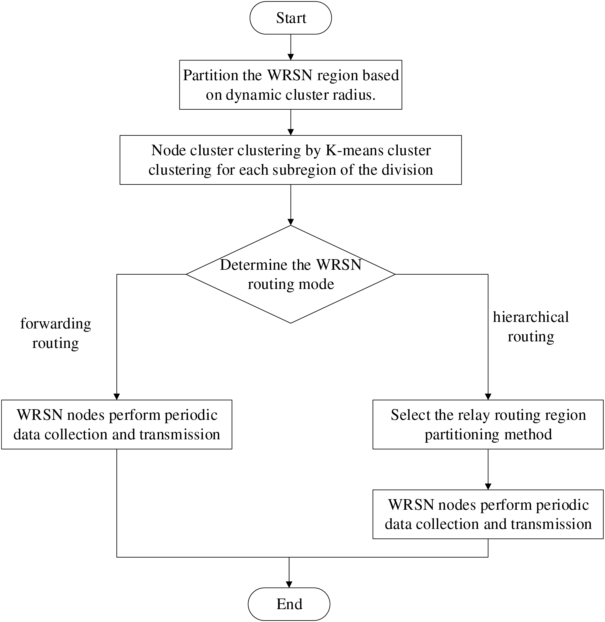
Figure 4: Algorithm implementation flowchart
4 Simulation Results and Analysis
4.1 Experimental Environment and Parameter Settings
The WRSN network model discussed in this paper is constructed using Python 3.8 on the PyCharm 2021 platform. The hardware environment for the experiment consists of an Intel(R) Core (TM) i5-11600KF processor running at 3.90 GHz with 16 GB of RAM, and the operating system is Windows 11 Professional. The experimental simulation parameters are set based on reference [24], as shown in Table 1.

4.2 Analysis of the Impact of Different Network Parameters on the Performance of Different Relay Routing Mechanisms
4.2.1 Analysis of Relay Routing Selection Function Parameters
Considering the impact of the relay routing selection function parameters as described in Eq. (13), this paper tests three different sets of parameter weights for three different factors. The selected parameter groups are as follows: Set 1:
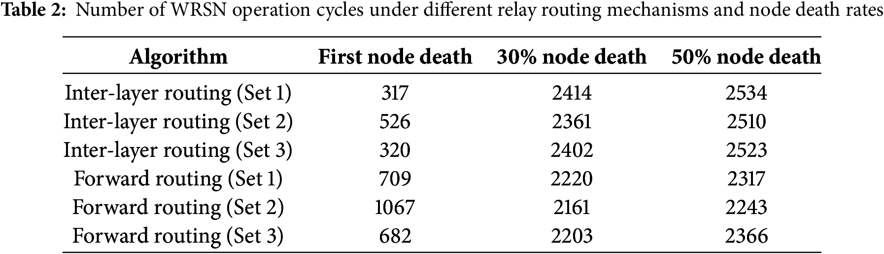
From Table 2, parameter group 2 significantly extends the number of rounds until the first node dies for both the forward routing and inter-layer routing mechanisms. However, the differences in the number of rounds until 30% and 50% of the nodes are dead among the three parameter groups are relatively small. Specifically, the inter-layer routing (Set 1) compared to inter-layer routing (Set 2) and inter-layer routing (Set 3) extends the rounds until the first node dies by 39.7% and 39.2%, respectively. Similarly, for the forward routing mechanism (Set 2), the rounds until the first node dies are extended by 33.6% and 36.1% compared to parameter groups 1 and 3, respectively. Thus, increasing the weight of the remaining energy factor of the cluster head in the three influencing factors can help avoid selecting cluster heads with low remaining energy as relay nodes, balance the energy consumption among relay nodes, and ultimately extend the lifetime of the WRSN.
To further validate the optimization of WRSN network performance and energy consumption with Set 1, the trends in the number of dead nodes, overall energy consumption, and network coverage under the three parameter groups for the two routing mechanisms are compared, as illustrated in Figs. 5–7, respectively. The method for calculating the network coverage is given in Eq. (14).
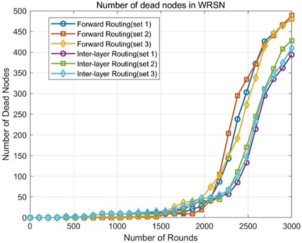
Figure 5: Trend of node death in WRSN under two routing mechanisms with different parameters
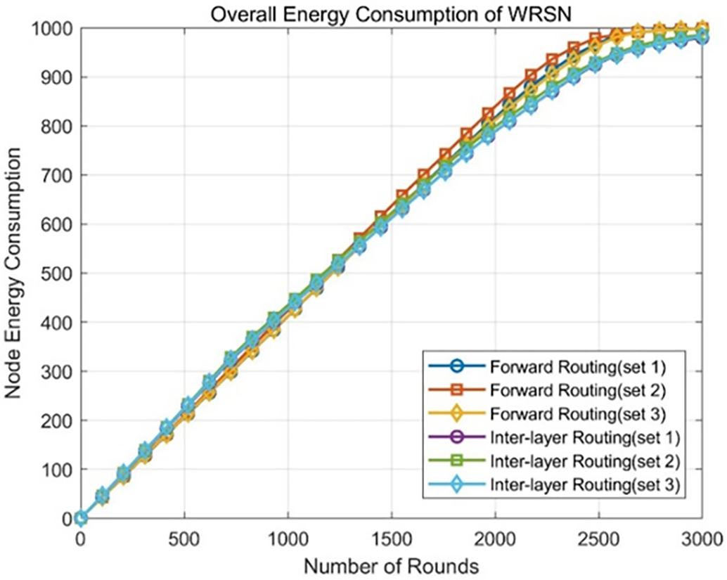
Figure 6: Trend of overall energy consumption in WRSN under two routing mechanisms with different parameters
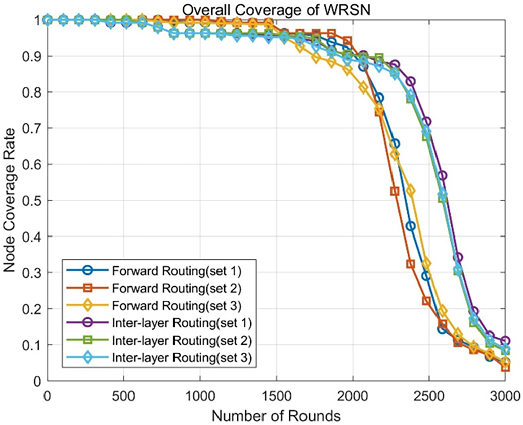
Figure 7: Trend of network coverage in WRSN under two routing mechanisms with different parameters
where
In Fig. 5, it is observed that for the inter-layer routing mechanism, the influence of the three parameter groups on the total number of dead nodes in the WRSN at round 3000 is relatively small. For the forward routing mechanism, the curve indicating the change in dead nodes shows that in the first 2000 rounds of operation, the number of dead nodes in forward routing (Set 2) is relatively similar to the other two parameter groups. However, in the following 1000 rounds, the number of dead nodes in forward routing (Set 2) increases compared to the other two parameter groups. Combining the observations from Figs. 6 and 7, the overall energy consumption of the WRSN under the three parameter groups is essentially the same, and the trends in coverage are quite similar. Since Set 2 effectively enhances the survival time of all nodes in the WRSN network, it is selected as the relay routing parameters for both the inter-layer routing mechanism and the forward routing mechanism.
4.2.2 Analysis of the Cluster Head Rotation Remaining Energy Threshold Parameter
Considering the impact of the cluster head rotation remaining energy threshold on the routing mechanism, three threshold values are selected for comparative experiments. In the WRSN network with 500 nodes, where the initial energy of each node is 2 J, the initial energies of 80%, 60%, and 40% are taken as the cluster head rotation remaining energy thresholds, denoted as

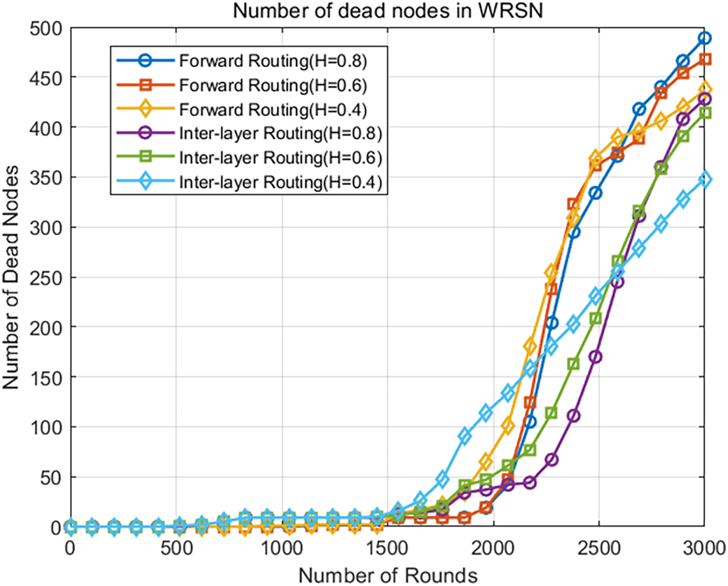
Figure 8: Trend of dead nodes in WRSN with different thresholds under two routing mechanisms
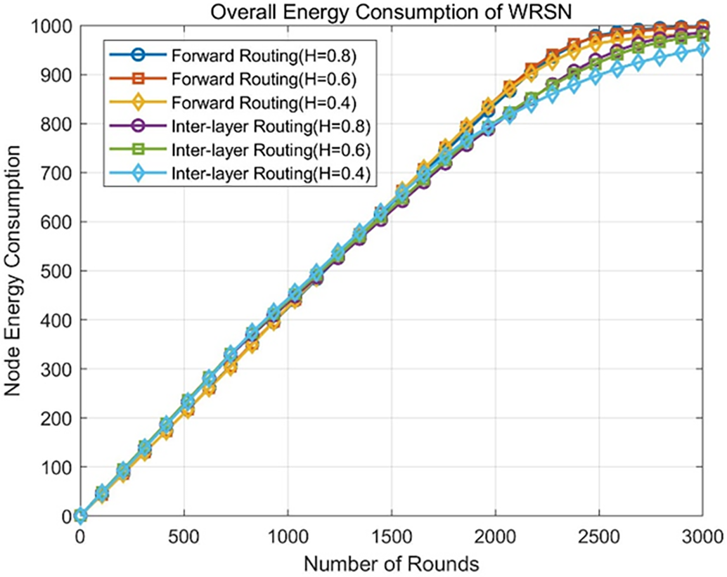
Figure 9: Trend of overall energy consumption in WRSN with different thresholds under two routing mechanisms
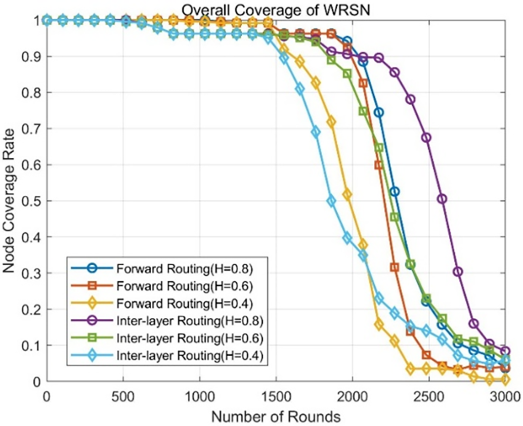
Figure 10: Trend of network coverage in WRSN with different thresholds under two routing mechanisms
From Table 3, when the cluster head rotation threshold is set to 0.8, the number of rounds until the first node dies for both the forward routing mechanism and the inter-layer routing mechanism increases by 12.1%, 20.5% and 7.6%, 20.5%, respectively, compared to the other two cluster head rotation thresholds. Additionally, the number of rounds until 30% and 50% of the nodes are dead also increases for both routing mechanisms when the threshold is set to 0.8 compared to the other thresholds.
Figs. 8 and 9 indicate that the three different thresholds have a minimal impact on the overall energy consumption of the WRSN under both the forward routing and inter-layer routing mechanisms. For the inter-layer routing mechanism, when
Selecting an optimal remaining energy threshold for cluster head rotation can better balance the energy consumption among intra-cluster nodes, reducing the number of surviving nodes in the network due to premature deaths of cluster heads caused by excessive energy consumption, which in turn enhances network coverage, monitoring area, and data collection quality. Based on the above experimental results, this paper selects
4.2.3 Analysis of Relay Routing Inter-Layer Structure Selection Method
This paper compares three relay routing structures for the inter-layer routing mechanism: typical two-hop routing (4-4 routing interval), three-hop routing (3-3-2 routing interval), and four-hop routing (2-2-2-2 routing interval). As before, 50 experiments are conducted to analyze the relay routing inter-layer structure, and the average values from these 50 experiments are taken for analysis. The trends in the number of dead nodes, overall energy consumption, and network coverage for the three relay routing inter-layer structures in the inter-layer routing mechanism are shown in Figs. 11–13.
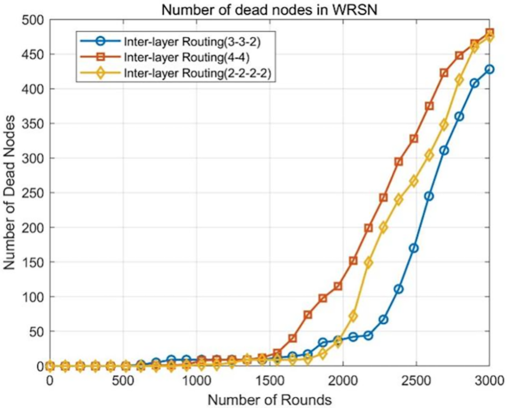
Figure 11: Trend of node death in WRSN with three different inter-layer relay routing structures
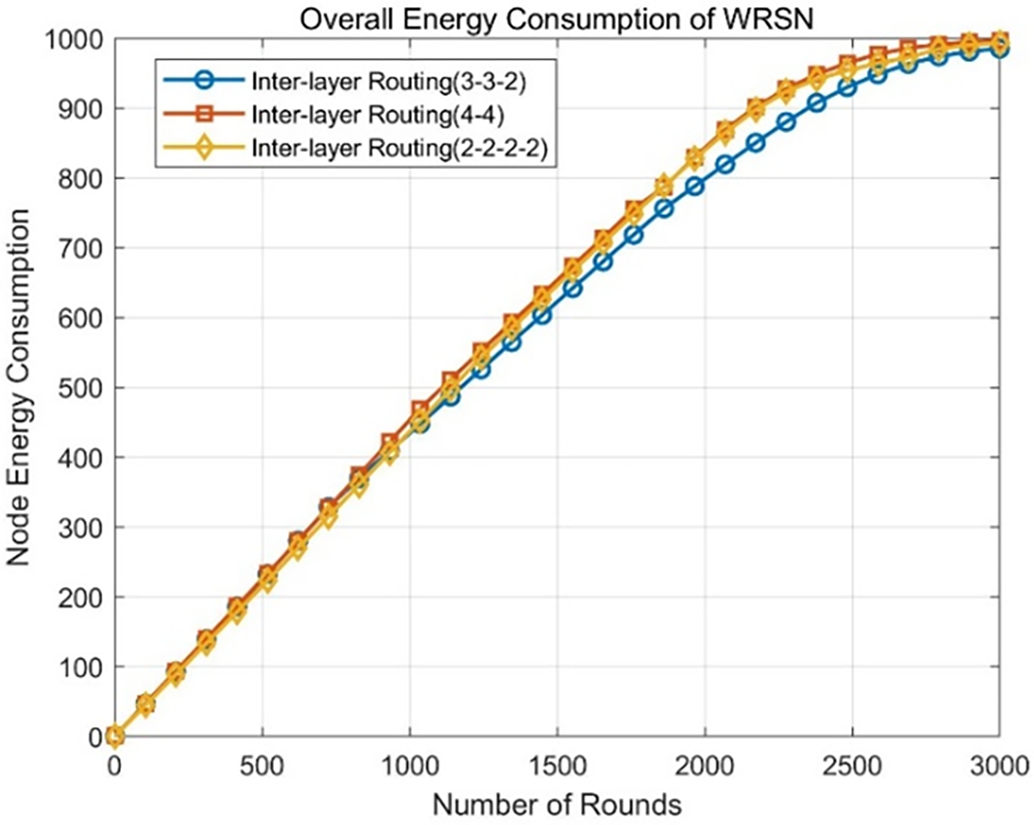
Figure 12: Trend of overall energy consumption in WRSN with three different inter-layer relay routing structures
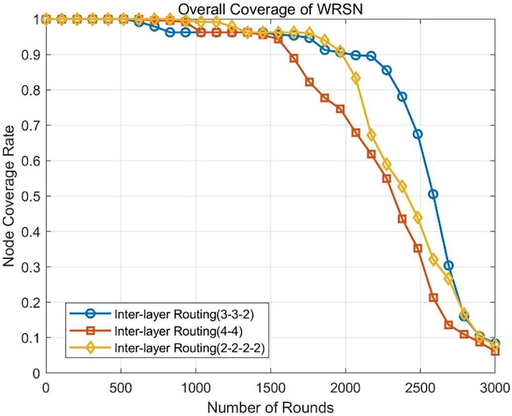
Figure 13: Trend of network coverage in WRSN with three different inter-layer relay routing structures
From Fig. 11, it can be observed that the number of dead nodes in the WRSN using the three-hop relay routing structure (3-3-2) remains lower than those using the two-hop (4-4) and four-hop (2-2-2-2) structures after 1500 rounds. By the 3000th round, the number of dead nodes for the (3-3-2) structure is 428, compared to 465 for the (2-2-2-2) structure and 475 for the (4-4) structure, representing a decrease of 8% and 9.9%, respectively. Additionally, Figs. 11 and 12 demonstrate that the (3-3-2) relay routing structure reduces overall energy consumption in the WRSN and significantly enhances network coverage. This is primarily since during the mid-operation phase of the WRSN, the last four layers of the (4-4) relay routing structure as relay cluster head nodes directly forward data from the first four layers to the base station. The longer data transmission distance leads to higher loads on the relay cluster heads in the last four layers, resulting in faster node deaths.
Although the (2-2-2-2) structure reduces the data transmission distance for individual inter-cluster relay routes, multiple relay hops increase the energy consumption for receiving and forwarding data by the relay cluster head nodes. Therefore, this paper selects the (3-3-2) relay routing structure as the inter-layer relay routing mechanism structure.
4.3 Performance Analysis of Energy Consumption Algorithm
To verify the effectiveness of the energy consumption optimization algorithm proposed in this paper, a comparative analysis is conducted between the inter-layer routing mechanism WRSN energy optimization algorithm (referred to as the proposed algorithm), the traditional forwarding clustering routing mechanism WRSN energy optimization algorithm (referred to as the traditional algorithm), the K-CLP algorithm [25], and the K-CHRA algorithm [26]. Tables 4 and 5 show the comparison of the number of dead nodes and cluster structures of the four algorithms under the same node deployment conditions for different network scales.


From Table 4, it can be observed that as the scale of the WRSN network increases, the node death rounds for the traditional algorithm, K-CLP, and K-CHRA algorithms tend to occur earlier. Notably, with a scale of 400 nodes, the first node death occurs significantly earlier, mainly due to the randomness in node distribution. At the scale of 500 nodes, the proposed algorithm extends the node death rounds for 30% and 50% of the nodes by 39.4% and 47.1% compared to K-CLP, and 19.3% and 8.3% compared to K-CHRA. Furthermore, compared to the traditional algorithm, the proposed algorithm reduces the number of dead nodes in the mid-term WRSN, extending the network’s lifespan. This is because the proposed algorithm employs inter-layer routing transmission, which, although it causes earlier deaths of relay nodes closer to the base station, avoids excessive relay transmissions among cluster head nodes and reduces the energy consumption of cluster head nodes across various layers.
Table 5 indicates that as the WRSN network scale increases, the number of clusters generated by all four algorithms increases. Due to the use of the same clustering method, the number of clusters generated by the traditional and proposed algorithms is the same but fewer than those produced by the K-CLP and K-CHRA algorithms, thus avoiding the occurrence of clusters with too few nodes. It can also be observed that for the same node scale, both the traditional and proposed algorithms exhibit fewer isolated cluster nodes. In a 500-node network, the clustering rate of the traditional algorithm/proposed algorithm is the highest at 92.8%, indicating its superior performance in maintaining node connectivity compared to K-CLP (77.4%) and K-CHRA (82.6%). A lower number of isolated cluster nodes indicates a more uniform distribution of cluster nodes generated by the clustering algorithm, reducing the need for charging individual cluster nodes, thereby enhancing charging efficiency and energy utilization.
Under the condition of deploying the same 500 nodes, a comparative analysis of the number of dead nodes, overall energy consumption, and charging mobility paths for the four algorithms is presented in Figs. 14–16.
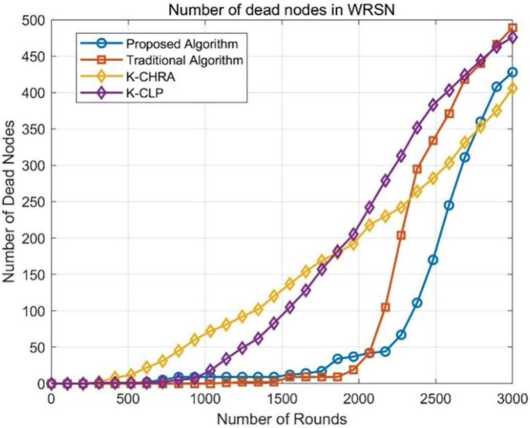
Figure 14: Trend of node deaths for four algorithms in a 500-node WRSN
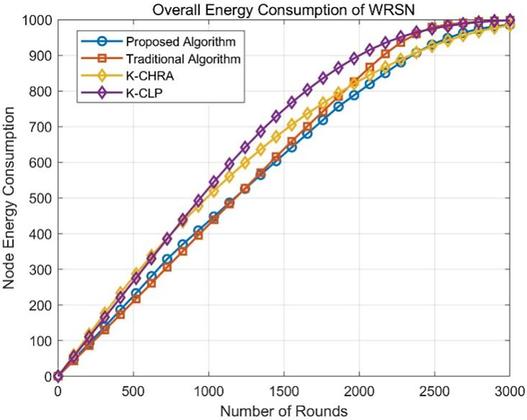
Figure 15: Structures trend of overall energy consumption for four algorithms in a 500-node WRSN
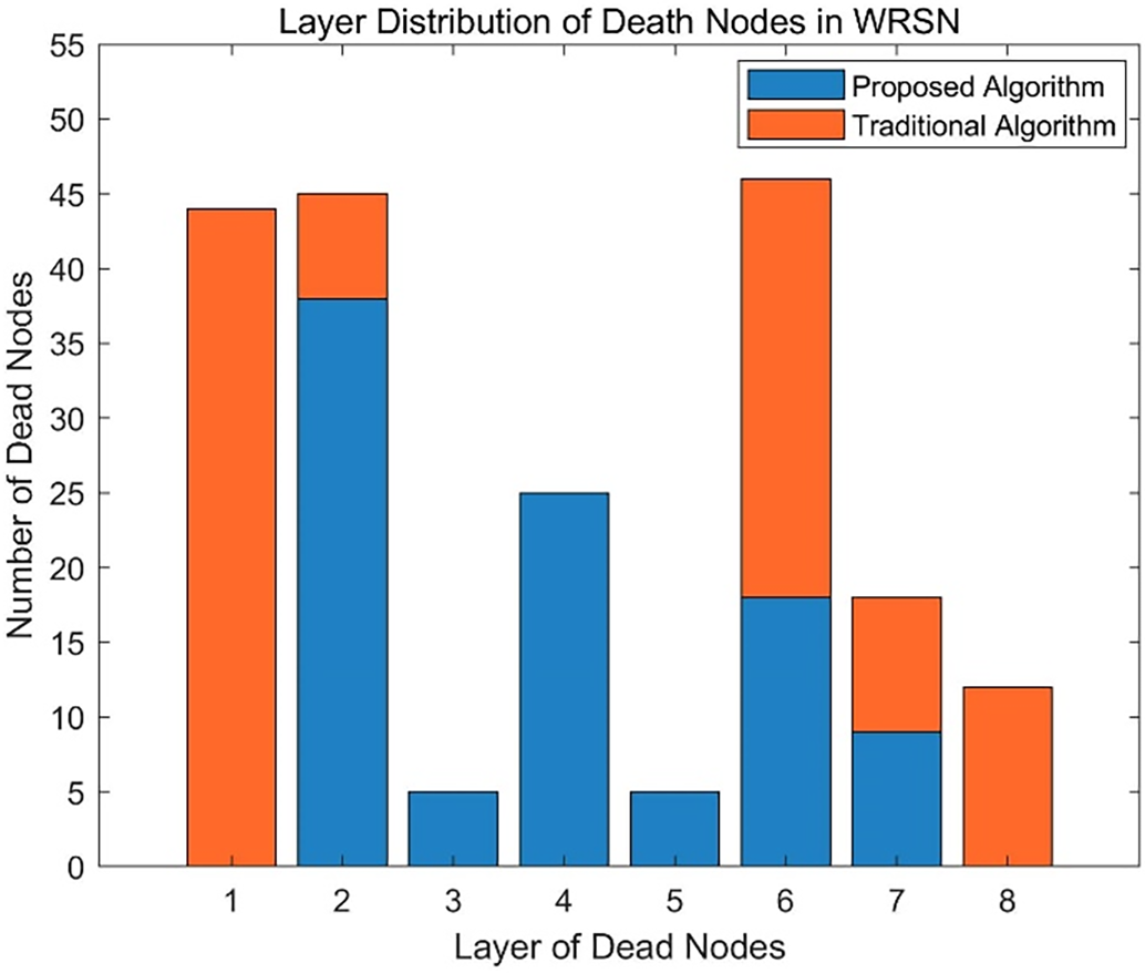
Figure 16: Distribution of the first 100 death node’s layers for the proposed algorithm and traditional algorithm
From Fig. 14, it is evident that the proposed algorithm results in a significantly lower number of dead nodes during the first 2500 rounds compared to the traditional algorithm, K-CLP, and K-CHRA algorithms. Additionally, both the proposed and traditional algorithms exhibit periods during the WRSN network’s operation where the number of dead nodes remains unchanged, whereas the K-CHRA and K-CLP algorithms show a continuous slow increase in the number of dead nodes.
Table 6 shows the energy consumption performance of different algorithms at rounds 1, 1000, 2000, and 3000 in Fig. 15. Combining this with Table 6 and Fig. 15, it can be concluded that the proposed algorithm effectively balances the energy consumption of various cluster nodes and inter-cluster relay head nodes during the early to mid-stage of network operation, thereby extending the network’s lifespan. During the middle and late stages of network operation, the overall energy consumption of the proposed algorithm is lower than that of the K-CLP and traditional algorithms, and is comparable to the K-CHRA algorithm.

The distribution of the first 100 dead nodes for the proposed and traditional algorithms across layers is illustrated in Fig. 16. From the figure, it is observed that the dead nodes of the proposed algorithm are primarily concentrated in the three layers closest to the base station and the outermost layer, while the dead nodes of the traditional algorithm are distributed across all layers. Therefore, when the MC conducts charging planning, the charging mobility path of the proposed algorithm is expected to be shorter than that of the traditional algorithm.
This paper proposes a WRSN node energy consumption optimization algorithm for large-scale WRSN environments. The algorithm incorporates a dynamic cluster radius-based region partitioning method to establish a hierarchical division of the WRSN monitoring area, with adaptive radius determination for individual sub-regions. Then, a K-means-based clustering algorithm is designed to optimize the generated cluster structure. Finally, by leveraging the hierarchical structure from region partitioning, an inter-layer routing mechanism is proposed to enable energy-efficient data relay transmission for WRSN cluster head nodes. The proposed algorithm’s efficacy is rigorously assessed through systematic parameter optimization and benchmark comparisons, demonstrating superior performance in energy conservation and operational sustainability. Experimental results demonstrate that the proposed algorithm achieves significant reductions in network-wide energy consumption, extends operational lifespan, and enhances both charging efficiency and energy utilization rates within WRSNs.
The simulation environment of the proposed algorithm is relatively ideal, and further research is needed for the complex WRSN environment with obstacles. In addition, on the basis of the research in this paper, how to further study the WRSN energy consumption optimization algorithm matching the WRSN charging planning scheme is a topic to be further studied.
Acknowledgement: The authors would like to express their gratitude for the valuable feedback and suggestions provided by all the anonymous reviewers and the editorial team.
Funding Statement: This research was funded by National Natural Science Foundation of China (No. 61741303), Guangxi Natural Science Foundation (No. 2017GXNSFAA198161), the Foundation Project of Guangxi Key Laboratory of Spatial Information and Mapping (No. 21-238-21-16).
Author Contributions: The authors confirm their contribution to the paper as follows: study conception and design: Cui Zhang, Lieping Zhang; draft manuscript preparation: Cui Zhang, Zhihao Li; methodology: Lieping Zhang; writing—reviewing & editing: Huaquan Gan; software: Hongyuan Chen, Zhihao Li. All authors reviewed the results and approved the final version of the manuscript.
Availability of Data and Materials: The data that support the findings of this study are available from the corresponding author, Lieping Zhang, upon reasonable request.
Ethics Approval: Not applicable.
Conflicts of Interest: The authors declare no conflicts of interest to report regarding the present study.
Abbreviations
| WRSN | Wireless Rechargeable Sensor Networks |
| WSN | Wireless Sensor Network |
| MC | Mobile Chargers |
References
1. Shakeri M, Sadeghi-Niaraki A, Choi SM, Riazul Islam SM. Performance analysis of IoT-based health and environment WSN deployment. Sensors. 2020;20(20):5923. doi:10.3390/s20205923. [Google Scholar] [PubMed] [CrossRef]
2. Wang Y, Feng Y, Liu M, Liu N. Dynamic spatio-temporal charging scheduling for WRSN based on deep reinforcement learning. J Softw. 2024;35(3):1485–501. doi:10.13328/j.cnki.jos.006814. [Google Scholar] [CrossRef]
3. Zhang Z, Pang H, Georgiadis A, Cecati C. Wireless power transfer—an overview. IEEE Trans Ind Electron. 2019;66(2):1044–58. doi:10.1109/TIE.2018.2835378. [Google Scholar] [CrossRef]
4. Padmanaban Y, Muthukumarasamy M. Scalable grid-based data gathering algorithm for environmental monitoring wireless sensor networks. IEEE Access. 2020;8:79357–67. doi:10.1109/ACCESS.2020.2990999. [Google Scholar] [CrossRef]
5. Zhang H, Jin H, Wang F. Exploration and research on energy saving in wireless sensor networks. Comput Eng Sci. 2021;2(43):295–303. doi:10.3969/j.issn.1007-130X.2021.02.014. [Google Scholar] [CrossRef]
6. Chen T, Chen J, Gao X, Chen T. Mobile charging strategy for wireless rechargeable sensor networks. Sensors. 2020;35:359. doi:10.3390/s22010359. [Google Scholar] [PubMed] [CrossRef]
7. Hu C, Wang Y, Wang H. Research progress on charging planning in wireless rechargeable sensor networks. J Softw. 2016;27(1):72–95. doi:10.13328/j.cnki.jos.004883. [Google Scholar] [CrossRef]
8. Han G, Yang X, Liu L, Chan S, Zhang W. A coverage-aware hierarchical charging algorithm in wireless rechargeable sensor networks. IEEE Netw. 2018;33(4):201–7. doi:10.1109/MNET.2018.1800197. [Google Scholar] [CrossRef]
9. Dong Y, Wang Y, Li S, Cui M, Wu H. Demand-based charging strategy for wireless rechargeable sensor networks. ETRI J. 2019;41(3):326–36. doi:10.4218/etrij.2018-0126. [Google Scholar] [CrossRef]
10. Han G, Guan H, Wu J, Chan S, Zhang W. An uneven cluster-based mobile charging algorithm for wireless rechargeable sensor networks. IEEE Syst J. 2018;13(4):3747–58. doi:10.1109/JSYST.2018.2879084. [Google Scholar] [CrossRef]
11. Zhou Y, Tao Y, Li Z, Yang L. Energy-efficient clustering routing algorithm based on evolutionary game theory for wireless sensor networks. Chin J Sens Actuators. 2020;33(3):436–42. doi:10.3969/j.issn.1004-1699.2020.03.019. [Google Scholar] [CrossRef]
12. Wang J, Jiang P. Large-scale WSN energy consumption optimization algorithm based on dynamic clustering. Control Eng China. 2020;12(S1):48–55. doi:10.14107/j.cnki.kzgc.161282. [Google Scholar] [CrossRef]
13. Boukerche A, Wu Q, Sun P. A novel joint optimization method based on mobile data collection for wireless rechargeable sensor networks. IEEE Trans Green Commun Netw. 2021;5(3):1610–22. doi:10.1109/TGCN.2021.3080918. [Google Scholar] [CrossRef]
14. Yi L, Xie Z, Chen K. A real-time charging algorithm based on nonuniform clustering. Chin J Sens Actuators. 2021;34(2):175–82. doi:10.3969/j.issn.1004-1699.2021.02.006. [Google Scholar] [CrossRef]
15. Sha C, Liu Q, Song S, Wang R. A type of annulus-based energy balanced data collection method in wireless rechargeable sensor networks. Sensors. 2018;18(9):3150. doi:10.3390/s18093150. [Google Scholar] [PubMed] [CrossRef]
16. Ijemaru G, Ang L, Seng K. Optimizing energy consumption and provisioning for wireless charging and data collection in large-scale WRSNs with mobile elements. IEEE Internet Things J. 2023;10(20):17585–602. doi:10.1109/JIOT.2023.3277667. [Google Scholar] [CrossRef]
17. Rajaram V, Pandimurugan V, Rajasoundaran S, Rodrigues P, Kumar SS, Selvi M, et al. Enriched energy optimized LEACH protocol for efficient data transmission in wireless sensor network. Wirel Netw. 2024;31(1):825–40. doi:10.1007/s11276-024-03802-5. [Google Scholar] [CrossRef]
18. Hu H, Fan X, Wang C. Energy efficient clustering and routing protocol based on quantum particle swarm optimization and fuzzy logic for wireless sensor networks. Sci Rep. 2024;14:18595. doi:10.1038/s41598-024-69360-0. [Google Scholar] [PubMed] [CrossRef]
19. Zhao X, Zhong W, Navaei YD. A novel energy-aware routing in wireless sensor network using clustering based on combination of multi-objective genetic and cuckoo search algorithm. Wirel Commun Mob Comput. 2022;2022:14. doi:10.1155/2022/6939868. [Google Scholar] [CrossRef]
20. Dong Y, Bao G, Liu Y, Wei M, Huo Y, Lou Z, et al. Instant on-demand charging strategy with multiple chargers in wireless rechargeable sensor networks. Ad Hoc Netw. 2022;136:102964. doi:10.11999/JEIT170927. [Google Scholar] [CrossRef]
21. Guo H, Wu R, Qi B, Xu C. Deep-q-networks-based adaptive dual-mode energy-efficient routing in rechargeable wireless sensor networks. IEEE Sens J. 2022;22(10):9956–66. doi:10.1109/JSEN.2022.3163368. [Google Scholar] [CrossRef]
22. Wang Z. Research on energy management strategy of wireless sensor network nodes. Chongqing, China: Chongqing University; 2017. [Google Scholar]
23. Jia H, Fan X, Lv Y. KACO: energy efficient routing protocol based on clustering algorithm. J Northwest Univ (Nat Sci Ed). 2017;47(5):681–6. doi:10.16152/j.cnki.xdxbzr.2017-10-010. [Google Scholar] [CrossRef]
24. Miao J, Zhao Y, Zui Y, Chen C, Ding H. Multi-hop routing algorithm with genetic and K-mean clustering in WSN. Mod Electron Tech. 2021;44(17):42–8. doi:10.16652/j.issn.1004-373x.2021.17.009. [Google Scholar] [CrossRef]
25. Dong Y, Cui M, Wu H, Wang Y. Charging scheduling for sub-cluster rechargeable wireless sensor networks based on energy prediction. J Jilin Univ (Eng Technol Ed). 2018;48(4):1265–73. doi:10.16652/j.issn.1004-373x.2021.17.009. [Google Scholar] [CrossRef]
26. Wei Z, Liu F, Ding X, Feng L, Lyu Z, Shi L. K-CHRA: a clustering hierarchical routing algorithm for wireless rechargeable sensor networks. IEEE Access. 2019;7:81859–74. doi:10.1109/ACCESS.2018.2885789. [Google Scholar] [CrossRef]
Cite This Article
 Copyright © 2025 The Author(s). Published by Tech Science Press.
This work is licensed under a Creative Commons Attribution 4.0 International License , which permits unrestricted use, distribution, and reproduction in any medium, provided the original work is properly cited.
 Downloads
 Citation Tools