
 Submit a Paper
 Propose a Special lssue
 Open Access
ARTICLE
Topology Optimization for Variable Thickness Shell-Infill Composites Based on Stress Analysis Preprocessing
National Center of Technology Innovation for Intelligent Design and Numerical Control, Huazhong University of Science and Technology, Wuhan, 430074, China
* Corresponding Author: Hao Li. Email:
(This article belongs to the Special Issue: Optimization Design for Material Microstructures)
Computers, Materials & Continua 2025, 85(1), 613-635. https://doi.org/10.32604/cmc.2025.068756
Received 05 June 2025; Accepted 16 July 2025; Issue published 29 August 2025
 View Full Text
 Download PDF
Abstract
Inspired by natural biomimetic structures exemplified by femoral bones, the shell-infill composite design has emerged as a research focus in structural optimization. However, existing studies predominantly focus on uniform-thickness shell designs and lack robust methodologies for generating high-resolution porous infill configurations. To address these challenges, a novel topology optimization framework for full-scale shell-filled composite structures is developed in this paper. First, a physics-driven, non-uniform partial differential equation (PDE) filter is developed, enabling precise control of variable-thickness shells by establishing explicit mapping relationships between shell thickness and filter radii. Second, this study addresses the convergence inefficiency of traditional full-scale topology optimization methods based on local volume constraints. It is revealed that a reduced influence radius exacerbates algorithm convergence challenges, thereby impeding the design of intricate porous structures. To overcome this bottleneck, a physics-driven stress skeleton generation method is developed. By integrating stress trajectories and rasterization processing, this method constructs an initial density field, effectively guiding material evolution and significantly enhancing convergence in porous structural optimization within the full-scale framework. Classical numerical examples demonstrate that our proposed optimization framework achieves biomimetic non-uniform shell thickness optimization and enables precise control of the shell thickness. Additionally, density preprocessing effectively eliminates intermediate density regions and void aggregation. Moreover, the generated trabecular-like infill patterns with spatially graded porosity, akin to multiscale topology optimization (MTO), provide an innovative solution for multifunctional, lightweight, complex shell-infill composite structures in aerospace and biomedical applications.Keywords
As an emerging technology garnering significant attention in recent years, additive manufacturing (AM) has enabled the practical fabrication of structures with complex geometric features [1–3]. Meanwhile, conventional configuration designs are increasingly unable to meet the growing comprehensive performance requirements in engineering fields. Inspired by the biological structures in nature, such as animal bones and plant stalks [4] (as shown in Fig. 1), which have been evolved over millions of years, shell-infill composite structures [5–7] have emerged as a prominent research focus in academia due to their excellent specific stiffness [8], specific strength [9], and lightweight properties [10]. The shell-infill composite structures, where rigid outer shells and internal spatial-varying porous infills synergistically share the structural load, enables them to balance load-bearing capacity and functional diversity, exhibiting notable superiority over conventional solid structures.
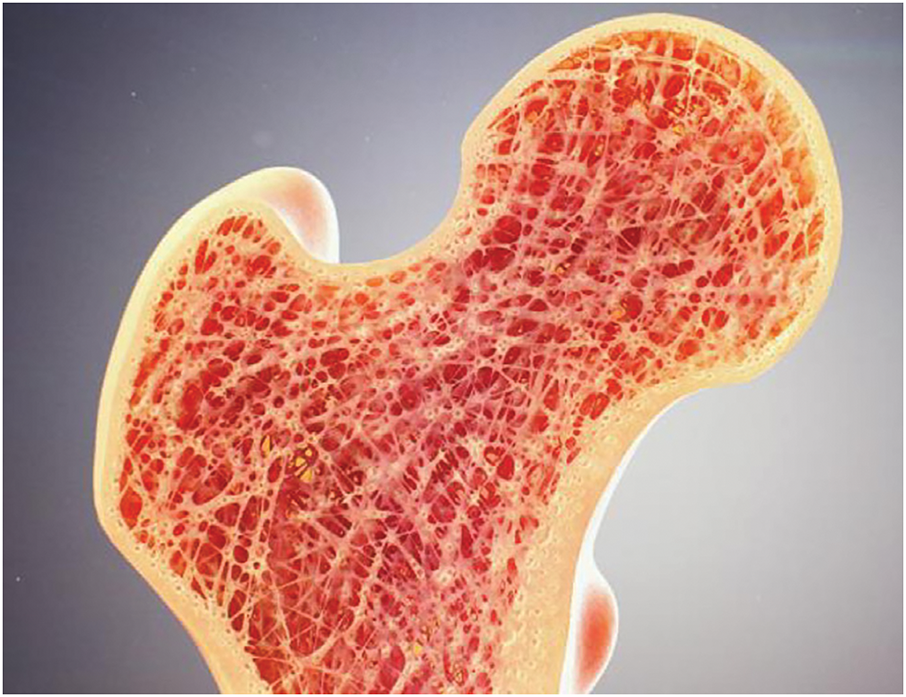
Figure 1: The shell-infill structures in nature, human bone (www.kashpersky.com)
Topology optimization, which can harness the full potential of design freedom, has become an efficient design tool for shell-infill composite structures [11–13]. Clausen et al. [14] first put forward a topology optimization method for coated structures, based on the SIMP (Solid Isotropic Microstructures with Penalization) material model [15,16]. Through multiple smoothing-projection processes, the external coating topology with uniform thickness is characterized by a density gradient field. Building upon this, Yi et al. [17] replaced the gradient field in the second phase with density filter and projection, which eliminated the coating thickness errors caused by gradient calculations. Luo et al. [18] streamlined the computation of the density gradient field, and introduced a density-based dilation-erosion framework. Furthermore, the precise mathematical expression linking the parameters of the filter-projection to the coating thickness was derived. Unlike density-based methods, Wang and Kang [19] achieved a unified representation of the matrix and coating features by employing a single level set function. However, the aforementioned studies on coated structures treat the internal infills as isotropic materials or single-type microstructures. Although this approach is computationally efficient and characterizes the coated and infill domains using a set of variables and their derived quantities, it has not fully exploited their design freedom. Furthermore, existing research on coated structures is largely confined to uniform thickness designs, whereas natural coatings often exhibit non-uniform thickness distributions to adapt to environmental stimuli. Consequently, the design potential of coated structures with spatially varying coatings remains underexplored.
In the pursuit of superior-performance configurations, homogeneous infill is being transitioned to gradient infill, primarily achieved through MTO [20–24], which can be traced back to the homogenization-based topology optimization framework proposed by Bendsøe and Kikuchi [25]. Rodrigues et al. [26] further advanced this framework by decoupling MTO problems into macroscopic and microscopic scale optimizations, yielding structures with distinct microstructural configurations. In recent years, the integration of coated structures with non-uniform infill has gained further development. Fu et al. [27] initialized the signed distance function, and a macro-level set function was employed to describe the uniformly-thick shell. Meanwhile, a micro-level set function was employed to describe the infilled single-type microstructures. Based on SIMP framework, Niu et al. [28] systematically considered the dynamic compliance of both the shell and infilled microstructures. However, similar to Fu’s work, their designed microstructures are restricted to a single type, a limitation that somewhat constrains the design freedom. Xu et al. [29] employed diverse microstructures to expand the design freedom of infill structures. A two-stage optimization strategy was adopted to address the computational intensity, enabling separate design phases for the shell and infilled microstructures. To ensure connectivity among different microstructures, solid shells were introduced between them. However, as the number of microstructure types increases, this method may become inefficient. Groen et al. [30] employed the density gradient field to identify the shell, achieved coupled macro-microstructural design using Rank-2 model with optimal performance under a single loading condition. Notably, a de-homogenization method was proposed to ensure smooth connectivity between distinct microstructures [31]. In summary, MTO still faces two major challenges: firstly, the enormous computational cost, and secondly, the difficulty of ensuring connectivity between different microstructures.
An alternative efficient design strategy for gradient-infilled structures was proposed by Wu et al. [32], through a topology optimization framework where the conventional global volume constraint is replaced by multiple local volume constraints, thereby compelling the material to distribute variably across the entire design domain in a spatially varying manner. Subsequently, Wu incorporated density-gradient-based shell identification into this framework, facilitating the generation of full-scale shell-infill structures [33]. Li et al. [34] implemented topology optimization for multi-phase infills based on pre-optimized coated structures, where maximum local volume constraints were imposed on different materials to avoid the formation of large solid or void regions. Yang et al. utilized local volume constraints to achieve robust designs of porous structures considering thermal-mechanical coupling [35] and fiber-reinforced structures [36], which not only circumvents the excessive computational costs associated with MTO, but also addresses the challenge of microstructural discontinuities caused by scale separation. However, as noted by Wang et al. [37], under certain special loading conditions, topology optimization based on local volume constraints may encounter difficulty in convergence, failing to yield binary “black-white” designs where material densities approach either 1 or 0 strictly. Thus, stress degenerate point analysis is employed for density preprocessing, effectively facilitating the convergence of the method proposed by Wu et al. [32].
The motivation of this study is to fully exploit the design freedom of shell-infill structures by: (1) proposing a density-based shell identification scheme with precise thickness control; and (2) developing a density preprocessing strategy using porous infill skeletons derived from global stress analysis for the generation of biologically inspired porous infill. Unlike prior studies, this paper leverages the local optimization characteristics of topology optimization, and amplifies the role of initial density on optimization outcomes. Specifically, a preprocessing strategy based on global stress skeleton analysis is proposed to facilitate the formation of stable gradient infill structures without explicit scale separation. The remainder of this paper is structured as follows: Section 2 details the variable-thickness shell identification scheme and the design method of infill structures. Section 3 details the stress trajectory generation method and the corresponding density preprocessing strategy. Section 4 validates the effectiveness and superiority of the proposed method through classical numerical examples. Section 5 concludes this work with a comprehensive discussion and outlines future research directions.
2 Topology Optimization of the Shell-Infill Structure
Unlike the conventional topology optimization of composite structures, in the shell-infill structure, specific materials are assigned to be distributed in different topological feature regions. As illustrated in Fig. 2, the outermost part of the structure is enveloped by shell materials of non-uniform thickness, while the interior is filled with dissimilar material phases. To achieve high-performance shell-infill composite structures, this paper explores design freedoms by focusing on shell thickness and the spatial graded distribution of infill. Within a density-based topology optimization framework, a physics-driven gradient filter was proposed, achieving precise characterization of variable-thickness shell features combined with the two-stage erosion-dilation strategy. Furthermore, a stress analysis strategy is developed to guide the design of graded infill materials, ultimately generating naturally connected porous infill phases with smooth spatial transitions.
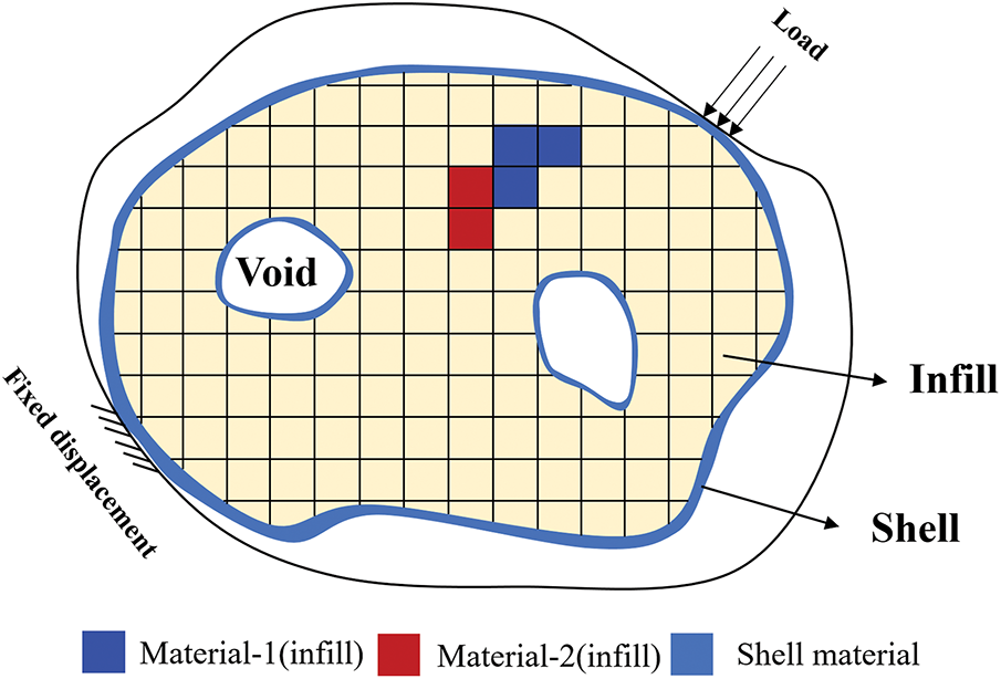
Figure 2: Schematic diagram of the topology optimization problem for variable-thickness shell-infill structures
2.2 Characterization of Variable Thickness Shell Topology
Conventional density-based shell identification methodologies predominantly rely on density gradient field. However, numerical discretization procedures applied to gradient fields in finite element analysis (FEA) introduce substantial discretization errors, significantly compromising precise shell thickness control. Recent advancements in erosion-dilation-based shell identification frameworks have demonstrated superior thickness controllability [18]. Building upon this, a framework for variable-thickness shell-infill structures is proposed, as shown in Fig. 3, and its core lies in the key procedure highlighted by the red frame. In contrast to the globally uniform PDE filter employed by Luo et al. [18], this paper develops an innovative variable-radius PDE filter that performs gradient-based smoothing operations on the initial density field
where R1 is the key to controlling the shell thickness, which is expanded from an invariant to a variable in this paper. s is the thickness of the structure prior to corrosion, and
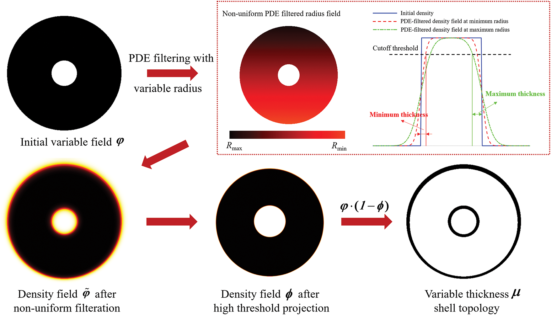
Figure 3: Schematic diagram of the characterization of variable thickness shell topology
In this study, the shell thickness distribution is physics-informed through a gradient-free optimization strategy. The methodology leverages element displacement fields to differentiate structural regions: performance-critical areas with large structural deformations receive thickened shell for enhanced load-bearing capacity, while non-critical areas with small deformations undergo thickness reduction to conserve material. Thus, the non-uniform PDE filter radius
where Rmin and Rmax represent the minimum and maximum allowable shell thicknesses, respectively. Ue denotes the elemental displacements, numerically equal to the numerical average of the displacements of its four nodes. Umin and Umax correspond to the minimum and maximum values of element displacement, respectively. More details can be referred to the work of Yang et al. [35]. The non-uniform shell topology μ is obtained for subsequent optimization of the porous infill structure.
2.3 Porous Infill Topology Optimization
Since our porous infill structure topology optimization framework builds upon the density-based approach with local volume constraints [32], a concise review of this foundational work is warranted: In contrast to conventional global volume constraints, a spatial discretization scheme that partitions the design domain into multiple circular subdomains was proposed. By converting the global material volume into localized volume ceilings for each subregion, this approach effectively suppresses the emergence of large-scale solid aggregates. The local volume constraint serves as a numerical realization of maximum geometric scale control, mathematically expressed as:
here,
Although the P-norm aggregation theoretically approaches
where V is the upper limit of the volume fraction in the infill domains.
Building upon the conventional density-based topology optimization framework and enhanced through the integration of local volume constraints, mathematical model for porous infill structure design can be proposed:
U denotes the global nodal displacement vector, and F represents the external load vector. The global stiffness matrix K, dependent on the Young’s modulus, is interpolated via the SIMP model. Particularly, the Young’s modulus expression can be defined as:
where E1 and E2 represent the Young’s moduli of the shell phase and the infilled material, respectively. To mitigate numerical singularities in the stiffness matrix during optimization, a small constant Emin = 10−9 is introduced in this paper.
It is crucial to emphasize that, to conduct the subsequent density preprocessing aimed at improving convergence, the optimization of the shell and the infill phases in this paper is carried out in two sequential stages. Specifically, the topology of the variable-thickness shell is first obtained based on the non-uniform PDE filter. Subsequently, the topology optimization of the porous infill phase is performed on this basis. This two-stage approach is adopted because the density preprocessing must be executed on a pre-known topology.
During the infill phase design, the discrete binary solutions (0 or 1) of the shell topology variables ( μ and ϕ) remain unchanged. These variables participate in the finite element analysis as a non-design domain at this stage. Consequently, these variables in Eq. (7) represent the finalized geometric boundaries and are exempt from penalty terms.
Similar to Eq. (3), each element’s design variable xi is filtered through a distance-dependent weighting scheme. This filtering operation aims to suppress checkerboard patterns through controlled spatial regularization [38], mathematically implemented as:
where x denotes the design variables directly engaged in the optimizer, and
The filtered intermediate variables
where
2.4.3 Relaxed Optimization Formulation
Incorporating the filtering and projection operations, the continuous optimization model for porous infill structures can be mathematically formulated as follows:
The gradient-based method of moving asymptotes (MMA) is employed in this study to update density variables. This approach requires the sensitivities of both the objective and constraint functions with respect to the design variables. Following the chain rule, these sensitivities can be derived as:
u denotes the nodal displacement vector of an element, while k0 represents the corresponding element stiffness matrix. For a more rigorous formulation, the sensitivities of intermediate variables can be derived as follows:
3 Density Preprocessing Strategy Based on Stress Analysis
In topology optimization problems involving complex design domains, the implementation of local volume constraints often leads to ambiguous principal stress orientations due to stress degradation phenomena, thereby hindering the generation of desired binary design. A representative case is demonstrated through the classical L-shaped beam design, as shown in Fig. 4, where the top edge is fully clamped and a vertical concentrated load is applied at the right-top corner. After 1000 iterations, although porous infill topology emerges within the L-shaped design domain, substantial regions remain unconverged with intermediate density distributions.
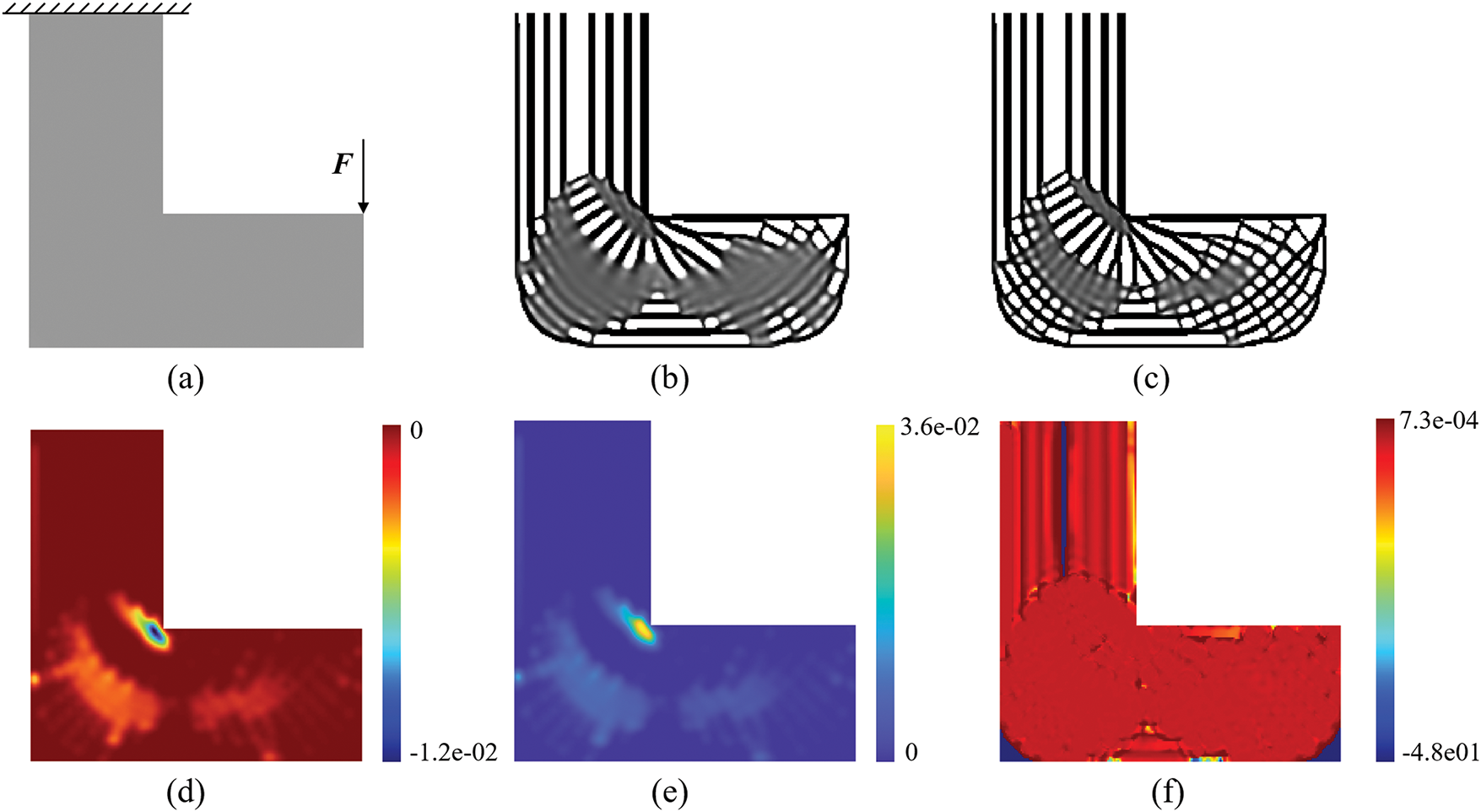
Figure 4: Topology optimization process of porous infill structures for L-beam. (a) Design domain and boundary conditions for L-beams (discretized into 200 × 200 elements). (b) Density distribution of porous infill structure at 500 iterations with local volume constraints, R2 = 7. (c) Density distribution of porous infill structure at 1000 iterations with local volume constraints, R2 = 7. (d) The sensitivity field of objective function
Sensitivity analysis reveals that both objective and constraint function sensitivities in unconverged regions significantly exceed those in other areas, as shown in Fig. 4d,e. It indicates that density increments in these regions would violate volume constraints, while density reductions would substantially compromise structural stiffness performance. The sensitivity ratio between objective and constraint functions plays a critical role in deriving the fixed-point update scheme of the Optimality Criteria (OC) framework. As illustrated in Fig. 4f, the relative sensitivities
3.1 Numerical Integration for Stress Trajectories
To address the convergence challenges in full-scale porous infill structure topology optimization frameworks, Delmarcelle and Hesselink [40] proposed a methodology involving the identification of stress trisectors and wedge-type degenerate points within the design domain. By leveraging the topological skeleton construction approach of Delmarcelle and Hesselink [40], the tangential principal stress directions at stress degenerate points is calculated to guide density updates in low-convergence regions. However, this method requires element-wise stress state discrimination and the solution of multiple sets of nonlinear equations, resulting in substantial computational complexity. This paper presents a density preprocessing method for porous topological skeletons based on stress analysis, where the stress state at any point in a two-dimensional design domain can be characterized as follows:
here,
here,
According to Michell’ work [41], the optimization design of porous infill structures requires adherence to principal stress distribution patterns to enhance initial structural performance. For arbitrarily complex design domains, principal stress trajectories can be constructed through the numerical integration illustrated in Fig. 5. The process begins with FEA to obtain nodal displacement fields, from which the stress tensor field is derived across all nodes. A continuous principal stress orientation field is subsequently established using inverse distance weighting interpolation (Fig. 5a). The principal stress trajectory tracing algorithm proceeds as follows: Starting from an arbitrary initial point Pi, a provisional point
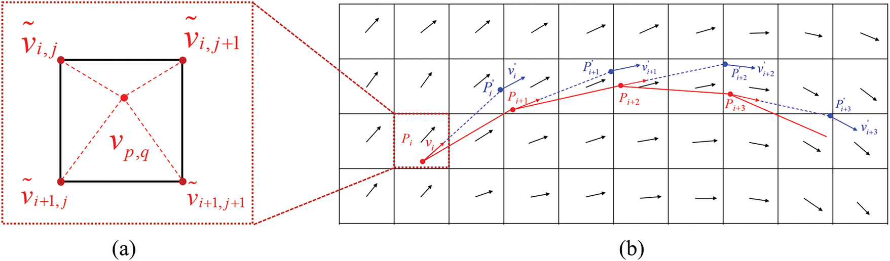
Figure 5: Stress trajectory generation based on vector integration. (a) The principal stress direction at any arbitrary point within the design domain, which is determined through inverse distance-weighted interpolation of principal stress directions from its four adjacent element nodes. (b) A continuous principal stress trajectory tracing methodology based on the Runge-Kutta method
3.2 Strategies for Generating Porous Topological Skeletons
The porous topological skeletons should be constructed through orthogonally interwoven principal and secondary principal stress trajectories. As a preprocessing phase for the framework proposed by Yang et al. [35], the skeleton generation should prevent the formation of large-scale solid regions or void concentrations during the initial iteration to satisfy local volume constraints. Building upon Jobard and Lefer’s [42] uniform streamline seeding algorithm, a seed point orthogonal coloring strategy driven by dual stress fields governed by principal and secondary principal stress fields is proposed.
The generation process of the porous topological skeleton is illustrated in Fig. 6. For arbitrary complex shape design domains, its centroid is first calculated as the initial integration point. Bidirectional integration along the principal stress direction based on the method described in Section 3.1 generates a continuous blue stress trajectory. A coloring bandwidth parameter I is defined to mark seed points within this distance from the existing blue trajectory as red, shown in Fig. 6a. Subsequently, secondary principal stress direction integration from the same initial point produces a red trajectory, while seed points within I from this red trajectory are marked blue, shown in Fig. 6b. Seed points receiving double markings undergo elimination, shown in Fig. 6b, completing one orthogonal coloring cycle. Particularly, colored seed points exclusively initialize trajectories of matching color, i.e., red seeds generate only red trajectories. During the iterative procedure, the closest valid colored seed to the initial point is prioritized for subsequent integration (Fig. 6c), continuing until no activatable seeds remain. This dynamic state updating mechanism enables self-organizing growth of the porous topological skeleton through systematic elimination of spatial candidates. This mechanism demonstrates dual functionality by preserving morphological uniformity of the porous skeleton while enhancing the efficiency of candidate seed point exclusion. The procedure advances through an integration-coloration-culling operational loop until reaching termination criteria triggered by exhaustion of activatable candidate seed points within the design domain, ultimately yielding a self-evolved porous topological skeleton. Fig. 6e–h resembles Fig. 6a–d, but with the dyeing bandwidth decreased from I = 10 to I = 7. As a result, the number of colored and excluded seed points reduces significantly, leading to an increase in stress trajectories and porosity of the porous topological skeleton, which is vital for improving the convergence of local volume constraints.
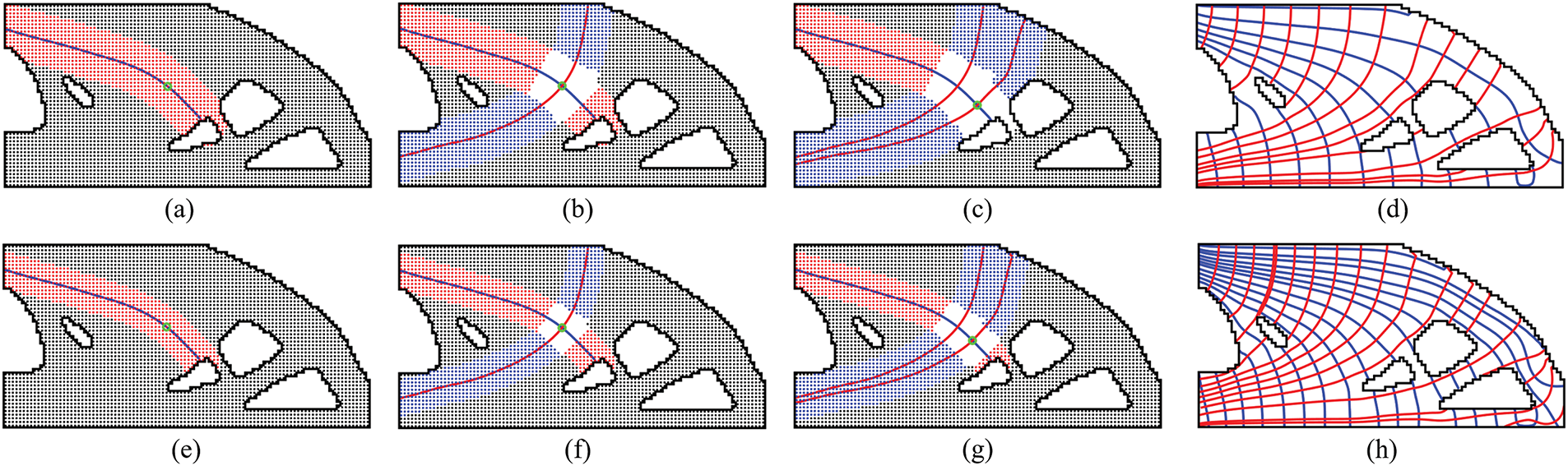
Figure 6: Generation process of the porous topological skeleton. (a) Red coloring process for seed points in the first iteration, seed spacing I = 10. (b) Blue coloring process for seed points in the second iteration, seed spacing I = 10. (c) Red coloring process for seed points in the third iteration, seed spacing I = 10. (d) Final porous topological skeleton, seed spacing I = 10. (e) Red coloring process for seed points in the first iteration, seed spacing I = 7. (f) Blue coloring process for seed points in the second iteration, seed spacing I = 7. (g) Red coloring process for seed points in the third iteration, seed spacing I = 7. (h) Final porous topological skeleton, seed spacing I = 7
The initial porous topological skeletons generated from continuous stress trajectories requires rasterization preprocessing for topology optimization [43]. For this purpose, the skeleton feature thickness control parameter t and FEA model mesh characteristic size d are defined. The elements whose centroids have a Euclidean distance less than t·d from any stress trajectory integration point are assigned an initial design variable of 1, as shown in Fig. 7 for the yellow elements. To ensure spatial continuity of skeleton elements, the numerical integration step of the stress trajectories h is set to d/2. In addition, the non-skeleton elements are initialized to:
where xnon denotes the initial density of non-skeleton elements.
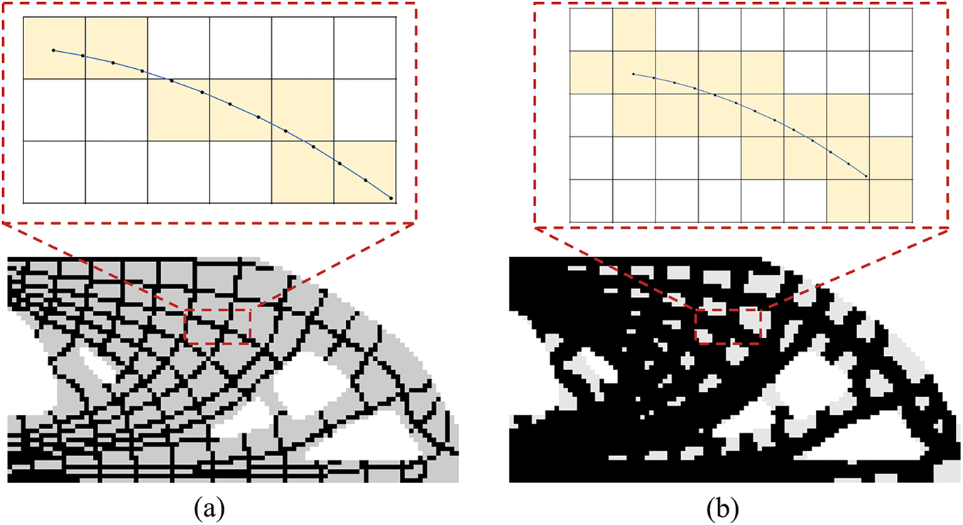
Figure 7: Rasterization preprocessing of porous topological skeletons. (a) Only the elements containing integration points along stress trajectories are assigned xe = 1. (b) With t = 1, elements whose centroids reside within a Euclidean distance d from stress trajectory integration points are initialized with xe = 1
In this section, several topology optimization examples of shell-infill composite structures are given to demonstrate the validity and superiority of the methodology we proposed. All physical quantities in this section are dimensionless, and the Young’s moduli of the infill-phase and shell materials are E1 = 1 and E2 = 2, respectively.
The Messerschmitt-Bölkow-Blohm (MBB) beam, a topology optimization benchmark, is employed in this section to investigate the effectiveness of our framework for shell-infill composite structures. As depicted in Fig. 8a, the design domain is discretized into a structured mesh of 400 × 200 quadrilateral elements. The left boundary is constrained against horizontal displacement, the lower right corner node is subjected to vertical displacement constraint, and a vertical concentrated load F = 1 is applied to the top-left node. The radius of density filter used to prevent the checkerboard patterns is Rf = 4.5. The shell thickness parameters are set as Rmax = 6 and Rmin = 3. Fig. 8b illustrates the non-uniform PDE-based filter radius R1 distribution contour map driven by displacement field responses. A positive correlation between displacement magnitude and filter radius is established: larger filter radii are adopted in high-displacement regions to generate thick shell features, whereas smaller radii in low-displacement zones yield thin shell configurations. As shown in Fig. 8c, the optimized MBB beam exhibits a well-defined shell feature. Local magnification reveals that the shell thickness in low-displacement regions precisely corresponds to 3 element side lengths, which validates the precision of the thickness constraint control methodology proposed in this work.
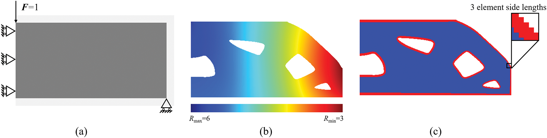
Figure 8: Topology optimization of coated MBB beam structure. (a) Design domain and boundary conditions. (b) Non-uniform PDE filter radius R1 distribution. (c) Optimized variable-thickness coated MBB beam structure, Rmax = 6, Rmin = 3
The coated structure illustrated in Fig. 8 is employed as a material indicator field for infill phase optimization design. The results obtained through a conventional full-scale topology optimization framework without density preprocessing are presented in Fig. 9. Fig. 9a–c displays the infilled density distribution after 200, 600, and 1000 iterations, respectively, where red and blue regions represent shell and infill phase materials. Under the MBB beam’s typical loading condition, even after 1000 iterations exceeding conventional convergence thresholds, the infill phase still exhibited a significant presence of intermediate density elements, indicating failure to achieve effective convergence in the optimization process. Further analysis of sensitivity distributions at the 1000th iteration reveals distinct characteristics: Fig. 9d–f respectively demonstrates the objective function sensitivity, constraint function sensitivity, and their ratio distribution. Fig. 9f shows that in non-converged regions, the sensitivity ratio between objective and constraint functions displays uniform characteristics, failing to provide directional gradient information essential for density field updates. This observation suggests that continued iteration would not resolve convergence issues, thereby highlighting inherent limitations of conventional approaches in porous infill structure design.
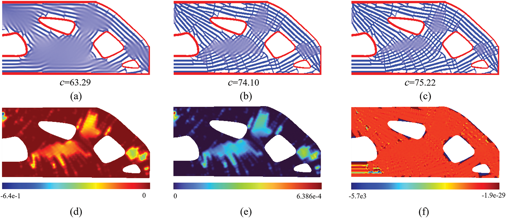
Figure 9: Topology optimization process of porous infill structures for MBB beam without density preprocessing, and the influence radius of the local volume constraint is R2 = 10. (a) Density distribution of porous infill structure after 200 iterations with local volume constraints. (b) Density distribution of porous infill structure after 600 iterations with local volume constraints. (c) Density distribution of porous infill structure after 1000 iterations with local volume constraints. (d) The sensitivity field of objective function
To enhance convergence performance in topology optimization framework under local volume constraints, a density preprocessing method based on porous topological skeletons is proposed. As shown in Fig. 10, for the optimized MBB beam coated structure, the method described in Section 3.1 generates global orthogonal stress trajectories that approximate equivalent Michell trusses to guide subsequent optimization, as shown in Fig. 10a. The density field was obtained by rasterizing the stress trajectories, and elements containing integral points of the stress trajectory are recognized as skeleton elements, as shown in Fig. 10b. Following this density preprocessing, an initial shell-infill composite structure with distinct geometric features is established for subsequent topology optimization, as shown in Fig. 10c.
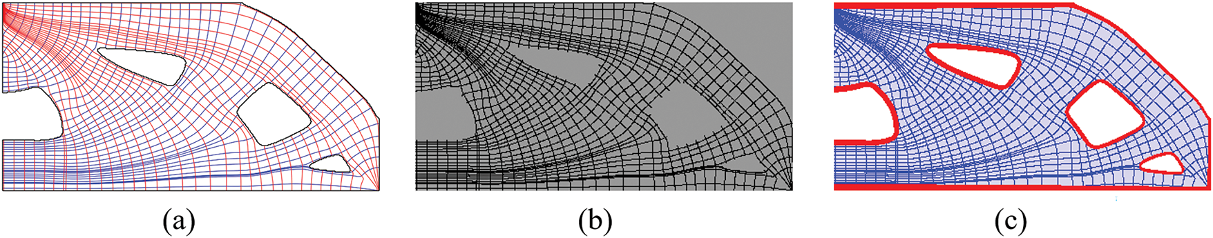
Figure 10: Density preprocessing for topology optimization design of MBB beam shell-infill composite structure. (a) Visualization of stress trajectories. (b) Density distribution following rasterization of stress trajectories. (c) Initial design of MBB beam shell-infill composite structure
Under the optimization framework incorporating porous topological skeleton preprocessing, Fig. 11 systematically demonstrates the dynamic evolution process of infill phase topology optimization for the MBB beam. To elucidate structural evolution patterns, configurations at every 100 iterations were employed to visualize the density field distribution. Notably, compared with conventional non-preprocessed methods requiring 1000 iterations yet still struggling with intermediate densities, our proposed approach achieved an ideal binary 0–1 density distribution within merely 300 iterations, as shown in Fig. 11c. Upon extending iterations to 600 steps, the density field remains stably converged without exhibiting notable alterations.
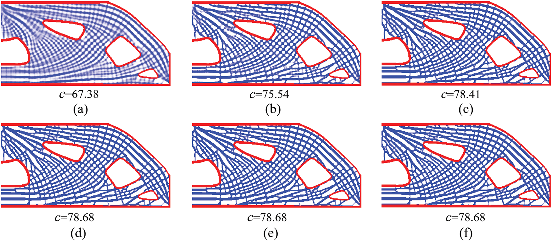
Figure 11: Topology optimization process of porous infill structures for MBB beam with density preprocessing, and the influence radius of the local volume constraint is R2 = 10. (a–f) The density distributions corresponding to 100, 200, 300, 400, 500, and 600 iterations, respectively
To delve into the underlying mechanism by which density preprocessing enhances the convergence of the algorithm, we conducted a detailed data analysis on the relative sensitivity
Figure 12: The relative sensitivity field
4.2 Bone-Like Porous Structure
As mentioned in previous sections, the design of shell-infill composite structures draws inspiration from natural biological systems. To validate the effectiveness of our proposed topology optimization framework for bionic structural design, this section establishes a 400 × 400 discretized design domain based on 2D CT scan images of human femurs. The topology optimization of bone-like porous structures is implemented through two phases: First, a shell thickness design is employed to extract interface characteristics and optimize material phase distribution between shell and infill regions. Subsequently, within a full-scale topology optimization framework, bone trabecula-like porous structures are systematically designed within the predetermined infill domains.
As shown in Fig. 13a, fixed displacement constraints are imposed on the basal surface of the femoral structure, while vertical upward and downward loads are applied at two load-bearing points on the superior femoral head. The radius of density filter used to prevent the checkerboard patterns is Rf = 4.5. Based on the displacement field derived from FEA, a non-uniform filter for shell thickness control is constructed based on the proposed method in Section 2.2, and the numerical optimization result demonstrates that the shell phase exhibits characteristic variable-thickness topological configurations. Specifically, pronounced thickness gradients emerge near load-bearing regions, showing strong spatial correlation with filtering field shown in Fig. 13b. This thickness gradient evolution aligns with biomechanical adaptation principles, where stress-concentrated zones develop mechanically enhanced shell materials to improve structural load-bearing efficiency.
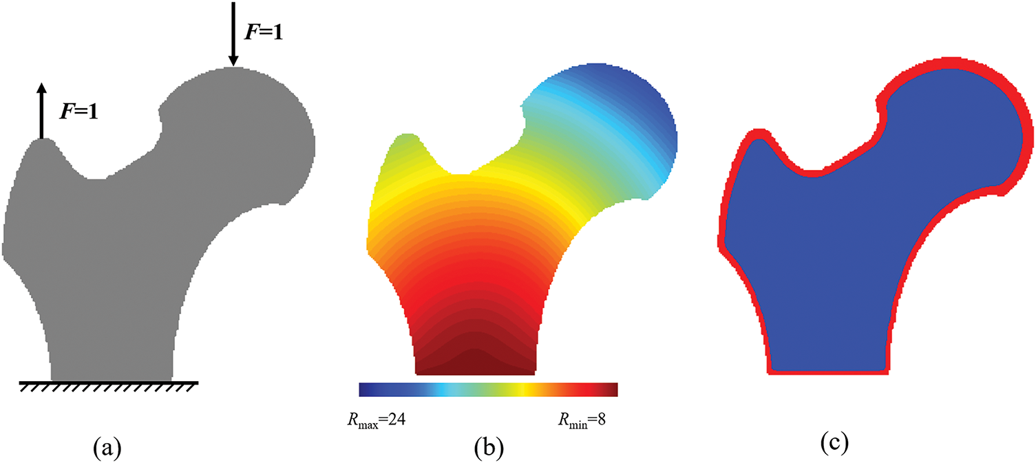
Figure 13: Topology optimization of coated bone-like porous structure. (a) Design domain and boundary conditions. (b) Non-uniform PDE-based filter radius R1 distribution (c) Optimized variable-thickness coated bone-like porous structure, Rmax = 24, Rmin = 8
Building upon the variable-thickness shell femoral structure shown in Fig. 13, full-scale topology optimization of porous infill structures was implemented. Initial configurations adopted a uniform density field (xe = 0.6) without preprocessing interventions, with local volume constraint influence radius set at R2 = 10. As illustrated in Fig. 14, significant gray material agglomeration persists after 1000 iterations, indicating non-convergence characteristics. Notably, Fig. 14e reveals abnormal void concentration within the infill domain, violating functional requirements of shell-infill composite structure. This phenomenon is attributed to these void regions being mechanically non-critical zones where material allocation provides limited stiffness enhancement. To address this, a straightforward idea is to reduce the influence radius of the local volume constraints to force that the porous structure can be more uniformly distributed in the infill domain. Thus, the local volume constraints are set to R2 = 6 and 8, and the resulting structures are shown in Fig. 15.
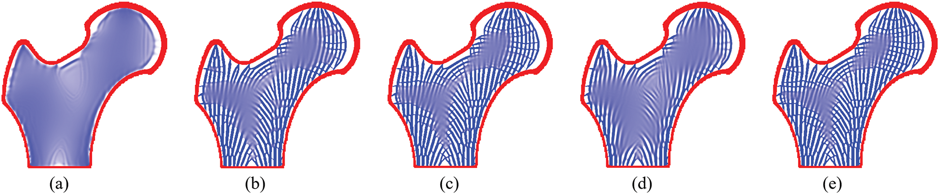
Figure 14: Topology optimization process of bone-like porous structure without density preprocessing, and the influence radius of the local volume constraint is R2 = 10. (a–e) The density distributions corresponding to 100, 300, 500, 700, 1000 iterations, respectively
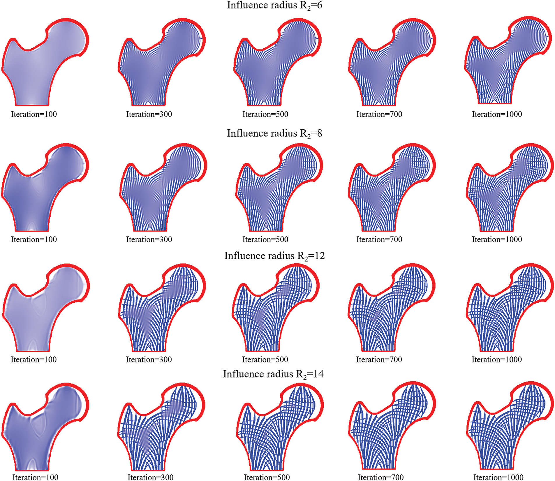
Figure 15: Topology optimization process of bone-like porous structures without density preprocessing at different influence radii
It can be observed that decreasing the influence radius R2 promotes the emergence of microstructural features with enhanced spatial uniformity within the infill domain, which aligns with the observations reported by Yang et al. [35]. However, the reduction in influence radius R2 resulted in a significant increase in intermediate-density elements in the structure, deteriorating the convergence of the optimization problem. To further investigate the effect of the influence radius R2 on the convergence of topology optimization for porous structures, we further enlarged the influence radius to R2 = 12 and R2 = 14. It was found that a strong correlation between increasing influence radius and reduction of intermediate density elements. Notably, at R2 = 12 and 14, the optimized structures achieve visually clear 0–1 binary density distribution. However, the porosity of the bone-like porous structure significantly decreased simultaneously, making it difficult to obtain trabecular-like structures with fine features.
To achieve fine-scale trabecular-like features while maintaining 0–1 binary density distributed bone-like shell-infill composite structure, the stress trajectory-based porous topological skeleton was implemented for density field preprocessing, as shown in Fig. 16a. The skeletal feature thickness parameter t was set to 1, i.e., the skeleton features are identified for domains that are not more than 1 element away from the stress trajectories. The preprocessed density distribution and initialized bone-like shell-infill composite structure are presented in Fig. 16b,c.
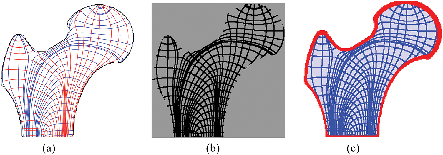
Figure 16: Density preprocessing for topology optimization design of bone-like porous structures. (a) Visualization of stress trajectories. (b) Density distribution following rasterization of stress trajectories. (c) Initial design of bone-like porous structures
Following porous topological skeleton-based density preprocessing, the optimized bone-like porous structures under varying constraint radii are presented in Fig. 17. Numerical examples demonstrate stabilized convergence across influence radii ranging from R2 = 6 to R2 = 14, confirming the efficacy of the preprocessing strategy in resolving non-convergence issues. Notably, reducing influence radii induces multiscale topological features within infill domains, successfully replicating the hierarchical characteristics of trabecular bone structures. What’s more, structural compliance exhibits a progressive increase with decreasing influence radii R2, attributed to constrained design freedom caused by intensified local volume restrictions.
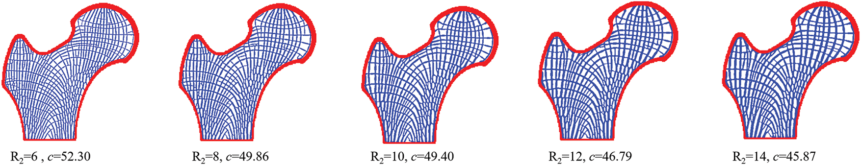
Figure 17: Topology optimization process of bone-like porous structures with density preprocessing at different influence radii, and the iteration number is 500
To further validate the effectiveness of our proposed density pre-processing method across different mesh scales, we examined significant mesh models of the hip bone structure: 600 × 600 and 200 × 200 elements. The initial and final designs under these differing mesh resolutions are presented in Fig. 18, from which the following observations can be made: 1. The initial designs obtained using our density pre-processing method are remarkably consistent, even under mesh resolutions differing by several-fold magnitudes. This consistency stems from the fact that the integration process within the stress trajectory tracing method presented in Fig. 5 operates in the parametric space, inherently making the stress skeleton largely mesh-independent. Although the mesh affects the calculation accuracy of stress states, this effect is significantly weakened after interpolation, making the stress skeleton less affected by the mesh. 2. The proposed method converges well at different resolutions, yielding clear porous infill structures. Notably, in the low-resolution model, the number of features in the porous infill phase decreases and the porosity significantly reduces compared to the high-resolution model. This phenomenon is expected, as coarser meshes capture fewer structural features due to the inherent loss of geometric detail. Crucially, the overall convergence and structural integrity across scales demonstrate the method’s effectiveness and robustness under varying mesh resolutions for structural applications.
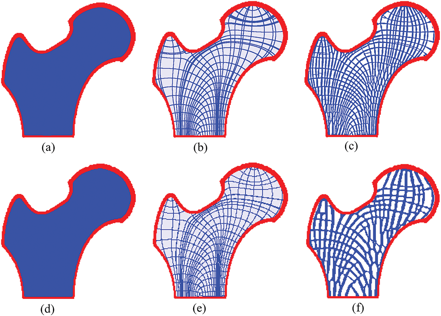
Figure 18: Optimization results of bone structures under different mesh resolutions. (a) Shell optimization result at 600 × 600 resolution. (b) Initial design of infill phase optimization at 600 × 600 resolution. (c) Final shell-infill design at 600 × 600 resolution. (d) Shell optimization result at 200 × 200 resolution. (e) Initial design of infill phase optimization at 200 × 200 resolution. (f) Final shell-infill design at 200 × 200 resolution
To systematically validate the efficacy of the proposed density preprocessing method in enhancing convergence for porous infill structure topology optimization, the convergence metric M is introduced to facilitate quantitative analysis of density evolution dynamics during the optimization process. M close to 1 indicates that the design variables have not converged at all and are all equal to 0.5, conversely, M close to 0 indicates that the design variables have all reached a binary distribution of 0–1. The expression for M is as follows [44]:
The iterative processes of the objective functions and convergence metrics for various cases are shown in Fig. 19. Numerical examples of porous structure topology optimization under local volume constraints reveal that initial density field configuration plays a decisive role in convergence characteristics. For uniformly initialized density fields, the objective functions exhibited pronounced non-monotonic oscillations with peak-to-valley variations. The convergence metric M showed a positive correlation with decreasing influence radius R2, reaching M = 0.46 at R2 = 6, indicative of substantial intermediate density elements. In contrast, the density preprocessing strategy significantly enhanced convergence stability. The profiles of the objective functions with density preprocessing demonstrated only 7 controlled stepwise transitions, corresponding to parameter β doubling events during optimization iterations. Except for R2 = 6, all other influence radii achieved near-zero M values, confirming near-binary 0–1 density distributions. Notably, under the R2 = 6 condition, preprocessing reduced M from 0.46 to 0.1 (78.3% decrease), demonstrating the critical role of our density preprocessing framework in resolving convergence challenges for local volume constrained porous structure optimization.
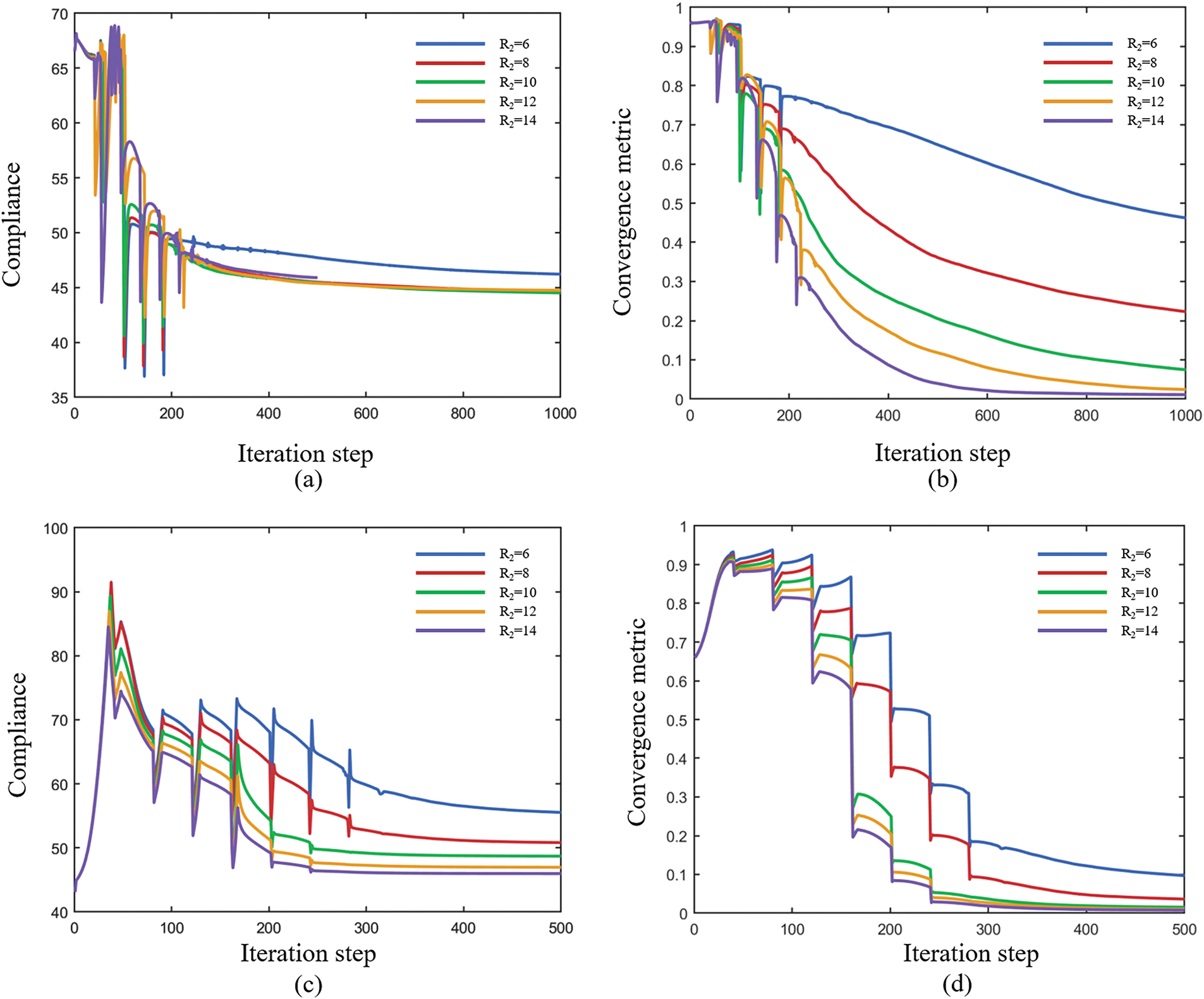
Figure 19: Iteration histories of objective function and convergence metric during bone-like shell-infill optimization. (a, b) Iteration histories of the compliance and convergence metric M without density preprocessing. (c, d) Iteration histories of the compliance and convergence metric M with density preprocessing
In this study, a full-scale topology optimization framework for variable-thickness shell-infill composite structures is proposed. Inspired by biomimetic structures in nature, a physics-driven non-uniform PDE filter is introduced to construct variable-thickness shell topologies via a density-based dilation-erosion strategy. Furthermore, an explicit relationship between shell thickness and filter radius is established to achieve precise control over shell thickness. Aiming at the convergence challenge caused by local volume constraints, where obtaining a manufacturable 0–1 binary density field remains difficult even after thousands of iterations, this paper presents a stress-driven porous topological skeleton generation method, which involves deploying uniform seed points across the design domain and performing stress trajectory integration. The initial density field of the porous infill structure is then constructed by identifying and assigning values to the initial variable field through rasterization techniques.
Two typical numerical examples show that our proposed method generates density fields with distinct shell and filler phase characteristics while achieving precise control of the thickness, both in free-form optimization and in the structural design of variable-thickness shell for a given profile. For the optimization challenges posed by the structural complexity of the infill domain, traditional initial density layouts with uniform distribution often face convergence challenges when handling full-scale topology optimization problems integrating local volume constraints. Specifically, a large number of intermediate density elements remain after 1000 iterations, and the relative sensitivities in non-convergent regions show no significant changes, leading to a lack of clear direction for density updates. Additionally, the study reveals that the convergence of the optimization problem is positively correlated with the influence radius of local volume constraints. By contrast, after preprocessing the density field using the proposed method, the optimization process achieves good convergence even at smaller influence radii, generating fine trabecular-like structures similar to those in MTO. Moreover, our method effectively mitigates the void aggregation phenomenon caused by traditional methods, enabling gradient distribution of porous infill structures across the entire infill domain. Future research directions include: (1) expanding single-phase infill to multiphase material infill for multifunctional biomimetic shell-infill composite structure design; and (2) upgrading the serial shell-infill stepwise design mode to a collaborative optimization design framework.
Acknowledgement: The authors appreciate the valuable comments from the reviewers and editors.
Funding Statement: This research is supported by the Defense Industrial Technology Development Program.
Author Contributions: Xuefei Yang: Writing—original draft, Software, Methodology. Ying Zhou: Validation, Conceptualization. Liang Gao: Formal analysis, Data curation. Hao Li: Writing—review & editing, Project administration, Funding acquisition. All authors reviewed the results and approved the final version of the manuscript.
Availability of Data and Materials: Data will be made available on request.
Ethics Approval: Not applicable.
Conflicts of Interest: The authors declare no conflicts of interest to report regarding the present study.
References
1. Wang W, Xia Y. Topology optimization based channel design for powder-bed additive manufacturing. Addit Manuf. 2022;54(1–4):102717. doi:10.1016/j.addma.2022.102717. [Google Scholar] [CrossRef]
2. Guo Y, Liu J, Ahmad R, Ma Y. Concurrent structural topology and fabrication sequence optimization for multi-axis additive manufacturing. Comput Methods Appl Mech Eng. 2025;435(6):117627. doi:10.1016/j.cma.2024.117627. [Google Scholar] [CrossRef]
3. Liu G, Zhang X, Chen X, He Y, Cheng L, Huo M, et al. Additive manufacturing of structural materials. Mater Sci Eng R Rep. 2021;145:100596. doi:10.1016/j.mser.2020.100596. [Google Scholar] [CrossRef]
4. Wegst UGK, Bai H, Saiz E, Tomsia AP, Ritchie RO. Bioinspired structural materials. Nat Mater. 2015;14(1):23–36. doi:10.1038/nmat4089. [Google Scholar] [PubMed] [CrossRef]
5. Qiu W, Jin P, Jin S, Wang C, Xia L, Zhu J, et al. An evolutionary design approach to shell-infill structures. Addit Manuf. 2020;34:101382. doi:10.1016/j.addma.2020.101382. [Google Scholar] [CrossRef]
6. Yu H, Huang J, Zou B, Shao W, Liu J. Stress-constrained shell-lattice infill structural optimisation for additive manufacturing. Virtual Phys Prototy. 2020;15(1):35–48. doi:10.1080/17452759.2019.1647488. [Google Scholar] [CrossRef]
7. Wang C, Zhang Y, Yu W, Yang S, Wang C, Jing S. Topology optimization of shell-infill structures for maximum stiffness and fundamental frequency. Compos Struct. 2025;356(10):118879. doi:10.1016/j.compstruct.2025.118879. [Google Scholar] [CrossRef]
8. Ha CS, Lakes RS, Plesha ME. Design, fabrication, and analysis of lattice exhibiting energy absorption via snap-through behavior. Mater Des. 2018;141(11):426–37. doi:10.1016/j.matdes.2017.12.050. [Google Scholar] [CrossRef]
9. Gibson L, Ashby M. Cellular solids: structure and properties. Cambridge, UK: Cambridge University Press; 1999. doi:10.1017/CBO9781139878326. [Google Scholar] [CrossRef]
10. Clausen A, Andreassen E, Sigmund O. Topology optimization of 3D shell structures with porous infill. Acta Mech Sin. 2017;3(4):778–91. doi:10.1007/s10409-017-0679-2. [Google Scholar] [CrossRef]
11. Liu K, Bai Y, Yao S, Luan S. Topology optimization of shell-infill structures for natural frequencies. Eng Comput. 2022;39(8):3083–107. doi:10.1108/EC-03-2022-0135. [Google Scholar] [CrossRef]
12. Li Y, Zhang Z, Luo J, Peng W, Zhou W, Yao W. Concurrent topology optimization of shells with pattern-guided infills for intuitive design and additive manufacturing. Comput Methods Appl Mech Eng. 2024;418(7):116485. doi:10.1016/j.cma.2023.116485. [Google Scholar] [CrossRef]
13. Zhang Y, Wang C, Yu W, Zhang C, Jing S, Wang C. Density penalty-based interface identification in shell-infill topology optimization. Struct Multidisc Optim. 2024;67(8):144. doi:10.1007/s00158-024-03871-2. [Google Scholar] [CrossRef]
14. Clausen A, Aage N, Sigmund O. Topology optimization of coated structures and material interface problems. Comput Methods Appl Mech Eng. 2015;290(6058):524–41. doi:10.1016/j.cma.2015.02.011. [Google Scholar] [CrossRef]
15. Bendsøe M, Sigmund O. Material interpolation schemes in topology optimization. Arch Appl Mech. 1999;69:635–54. doi:10.1007/s004190050248. [Google Scholar] [CrossRef]
16. Bendsøe M, Sigmund O. Topology optimization: theory, method and applications. Berlin/Heidelberg, Germany: Springer Science & Business Media; 2003. doi:10.1007/978-3-662-05086-6. [Google Scholar] [CrossRef]
17. Yi B, Yoon H, Peng X. A simple density filter for the topology optimization of coated structures. Eng Optim. 2021;53(12):2088–107. doi:10.1080/0305215X.2020.1845326. [Google Scholar] [CrossRef]
18. Luo Y, Li Q, Liu S. Topology optimization of shell-infill structures using an erosion-based interface identification method. Comput Methods Appl Mech Eng. 2019;355:94–112. doi:10.1016/j.cma.2019.05.017. [Google Scholar] [CrossRef]
19. Wang Y, Kang Z. A level set method for shape and topology optimization of coated structures. Comput Methods Appl Mech Eng. 2018;329:553–74. doi:10.1016/j.cma.2017.09.017. [Google Scholar] [CrossRef]
20. Costa M, Sohouli A, Suleman A. Multi-scale and multi-material topology optimization of gradient lattice structures using surrogate models. Compos Struct. 2022;289(5):115402. doi:10.1016/j.compstruct.2022.115402. [Google Scholar] [CrossRef]
21. Duriez E, Morlier J, Charlotte M, Azzaro-Pantel C. A well connected, locally-oriented and efficient multi-scale topology optimization (EMTO) strategy. Struct Multidisc Optim. 2021;64(6):3705–28. doi:10.1007/s00158-021-03048-1. [Google Scholar] [CrossRef]
22. Wu J, Sigmund O, Groen J. Topology optimization of multi-scale structures: a review. Struct Multidisc Optim. 2021;63(3):1455–80. doi:10.1007/s00158-021-02881-8. [Google Scholar] [CrossRef]
23. Zhang C, Xu S, Liu J, Ma Y. Comprehensive clustering-based topology optimization for connectable multi-scale additive manufacturing structures. Addit Manuf. 2022;54:102786. doi:10.1016/j.addma.2022.102786. [Google Scholar] [CrossRef]
24. Zhou M, Geng D. Multi-scale and multi-material topology optimization of channel-cooling cellular structures for thermomechanical behaviors. Comput Methods Appl Mech Eng. 2021;383(2):113896. doi:10.1016/j.cma.2021.113896. [Google Scholar] [CrossRef]
25. Bendsøe M, Kikuchi N. Generating optimal topologies in structural design using a homogenization method. Comput Methods Appl Mech Eng. 1988;71(2):197–224. doi:10.1016/0045-7825(88)90086-2. [Google Scholar] [CrossRef]
26. Rodrigues H, Guedes J, Bendsøe M. Hierarchical optimization of material and structure. Struct Multidisc Optim. 2002;24(1):1–10. doi:10.1007/s00158-002-0209-z. [Google Scholar] [CrossRef]
27. Fu J, Li H, Xiao M, Gao L, Chu S. Topology optimization of shell-infill structures using a distance regularized parametric level-set method. Struct Multidisc Optim. 2019;59(1):249–62. doi:10.1007/s00158-018-2064-6. [Google Scholar] [CrossRef]
28. Niu B, Yan J, Cheng G. Optimum structure with homogeneous optimum cellular material for maximum fundamental frequency. Struct Multidisc Optim. 2009;39(2):115–32. doi:10.1007/s00158-008-0334-4. [Google Scholar] [CrossRef]
29. Xu S, Liu J, Huang J, Zou B, Ma Y. Multi-scale topology optimization with shell and interface layers for additive manufacturing. Addit Manuf. 2021;37(1–2):101698. doi:10.1016/j.addma.2020.101698. [Google Scholar] [CrossRef]
30. Groen J, Wu J, Sigmund O. Homogenization-based stiffness optimization and projection of 2D coated structures with orthotropic infill. Comput Methods Appl Mech Eng. 2019;349:722–42. doi:10.1016/j.cma.2019.02.031. [Google Scholar] [CrossRef]
31. Groen J, Sigmund O. Homogenization-based topology optimization for high-resolution manufacturable microstructures. Int J Numer Methods Eng. 2017;113(8):1148–63. doi:10.1002/nme.5575. [Google Scholar] [CrossRef]
32. Wu J, Aage N, Westermann R, Sigmund O. Infill optimization for additive manufacturing—approaching bone-like porous structures. IEEE Trans Vis Comput Graph. 2017;24(2):1127–40. doi:10.1109/TVCG.2017.2655523. [Google Scholar] [PubMed] [CrossRef]
33. Wu J, Clausen A, Sigmund O. Minimum compliance topology optimization of shell-infill composites for additive manufacturing. Comput Methods Appl Mech Eng. 2017;326(2):358–75. doi:10.1016/j.cma.2017.08.018. [Google Scholar] [CrossRef]
34. Li H, Li H, Gao L, Zheng Y, Li J, Li P. Topology optimization of multi-phase shell-infill composite structure for additive manufacturing. Eng Comput. 2024;40(2):1049–64. doi:10.1007/s00366-023-01837-4. [Google Scholar] [CrossRef]
35. Yang X, Li H, Gao L. Thermal-mechanical coupling topology optimization of multi-phase infill structures with a non-gradient porosity optimization method. Int J Heat Mass Transf. 2023;210(15):124198. doi:10.1016/j.ijheatmasstransfer.2023.124198. [Google Scholar] [CrossRef]
36. Yang X, Gao L, Li H. Multi-feature parallel topology optimization of fiber-reinforced coated structures based on a dual variable scale filtering method. Compos Struct. 2024;341(3):118227. doi:10.1016/j.compstruct.2024.118227. [Google Scholar] [CrossRef]
37. Wang J, Wu J, Westermann R. Stress topology analysis for porous infill optimization. Struct Multidisc Optim. 2022;65(3):92. doi:10.1007/s00158-022-03186-0. [Google Scholar] [CrossRef]
38. Díaz A, Sigmund O. Checkerboard patterns in layout optimization. Struct Optim. 1995;10(1):40–5. doi:10.1007/BF01743693. [Google Scholar] [CrossRef]
39. Wang F, Lazarov B, Sigmund O. On projection methods, convergence and robust formulations in topology optimization. Struct Multidisc Optim. 2011;43(6):767–84. doi:10.1007/s00158-010-0602-y. [Google Scholar] [CrossRef]
40. Delmarcelle T, Hesselink L. The topology of symmetric, second-order tensor fields. In: Proceedings of the Conference on Visualization ’94; 1994 Oct 21; Washington, DC, USA. p. 140–7. doi:10.1109/VISUAL.1994.346326. [Google Scholar] [CrossRef]
41. Michell A. LVIII, the limits of economy of material in frame-structures. Lond Edinb Dublin Philos Mag J Sci. 1904;8(47):589–97. doi:10.1080/14786440409463229. [Google Scholar] [CrossRef]
42. Jobard B, Lefer W. Creating evenly-spaced streamlines of arbitrary density. Vis Sci Comput. 1997;97(4):43–55. doi:10.1007/978-3-7091-6876-9_5. [Google Scholar] [CrossRef]
43. Wang J, Wu J, Westermann R. Stress trajectory guided structural design and topology optimization. In: Proceedings of the ASME, 2022 International Design Engineering Technical Conferences and Computers and Information in Engineering Conference; 2022 Aug 14–17; St. Louis, MO, USA. doi:10.1115/DETC2022-89030. [Google Scholar] [CrossRef]
44. Sigmund O. Morphology-based black and white filters for topology optimization. Struct Multidisc Optim. 2007;33:401–24. doi:10.1007/s00158-006-0087-x. [Google Scholar] [CrossRef]
Cite This Article
 Copyright © 2025 The Author(s). Published by Tech Science Press.
This work is licensed under a Creative Commons Attribution 4.0 International License , which permits unrestricted use, distribution, and reproduction in any medium, provided the original work is properly cited.
 Downloads
 Citation Tools