
 Submit a Paper
 Propose a Special lssue
 Open Access
ARTICLE
An Inverted Pendulum System Control with Fuzzy Linear Quadratic Regulator Method: Experimental Validation
Department of Mechanical Engineering, Muş Alparslan University, Muş, 49100, Türkiye
* Corresponding Authors: Tayfun Abut. Email: ,
(This article belongs to the Special Issue: Advancements in Natural Language Processing (NLP) and Fuzzy Logic)
Computers, Materials & Continua 2025, 85(2), 4023-4042. https://doi.org/10.32604/cmc.2025.066920
Received 21 April 2025; Accepted 13 August 2025; Issue published 23 September 2025
 View Full Text
 Download PDF
Abstract
In this study, a dynamic model for an inverted pendulum system (IPS) attached to a car is created, and two different control methods are applied to control the system. The designed control algorithms aim to stabilize the pendulum arms in the upright position and the car to reach the equilibrium position. Grey Wolf Optimization-based Linear Quadratic Regulator (GWO-LQR) and GWO-based Fuzzy LQR (FLQR) control algorithms are used in the control process. To improve the performance of the LQR and FLQR methods, the optimum values of the coefficients corresponding to the foot points of the membership functions are determined by the GWO algorithm. Both a graphic and a numerical analysis of the outcomes are provided. In the comparative analysis, it is observed that the GWO-based FLQR method reduces the settling time by 22.58% and the maximum peak value by 18.2% when evaluated in terms of the angular response of the pendulum arm. Furthermore, this approach outperformed comparable research in the literature with a settling time of 2.4 s. These findings demonstrate that the suggested GWO-based FLQR control method outperforms existing literature in terms of the time required for the pendulum arm to reach equilibrium.Keywords
The inverted pendulum system (IPS) is an incompletely driven system in which control methods are tested. These systems are used in a wide area [1–3]. Real-time balancing of these systems is challenging task. Theoretical studies in the literature are quite abundant, but real-time application of the suggested methods in an experimental environment is scarce [4–6]. Experimental studies are presented in the literature section of this study. In particular, experimental studies utilizing LQR and Fuzzy Logic Controller (FLC) methods are described. Prof. Lotfi A. Zadeh of Azerbaijan studied fuzzy logic theory. In his research, Zadeh suggested that humans’ superior capacity to operate particular systems over machines originates from their capacity to make decisions based on specific, ambiguous information. The processes involved in fuzzy logic operations include problem identification and analysis, variable clustering and logic relation building, knowledge conversion into fuzzy sets, and model interpretation [7]. Hung and Fernandez realized the comparative control of an IPS in real time [8]. In the study, proportional-derivative, sliding mode, fuzzy, expert system, and neural network control methods were used. As a result of the study, the strengths and weaknesses of the methods in real-time control were shown. A Fuzzy LQR control approach for an IPS was created by Sáez and Cipriano, and it was used in simulation and actual testing environments [9]. The FLQR controller achieved better results in terms of angular stabilization of the IPS than a conventional LQR method. For the process of an IPS mechanical system, Chen and Chen developed an adaptive control, architecture based on a fuzzy model and put it into practice in an experimental setting [10]. In this study, the position of the cart was limited to 0.008 m, and the angle to 0.4 degrees. The effectiveness of the suggested controller for an unstable nonlinear system with unknown uncertainties was demonstrated. In another study, an IPS was controlled in an experimental environment with FLC using visual feedback [11]. It was shown that control using FLC and visual feedback is possible within certain limits. Teng tested three Matlab/Simulink-based software systems in real-time. Real-time implementations of PID, LQR controller, and FLC methods in WinCon 2.0, Real-Time Toolbox 3.0, and xPC Target 1.0 software were demonstrated [12].
Nundrakwang et al. [13] designed an LQR control method for the stabilization of the pendulum in which PD control was applied for the upright position of the pendulum, and a servo state feedback control was carried out in real-time. Despite its simplicity in design, the suggested method proved effective, yielding the desired system performance. Muskinja and Tovornik experimentally carried out the swing-up and stabilization of an IPS utilizing the FLC method [14]. They compared the FLC method with energy-based oscillation strategies and showed its advantages. Gawthrop and Wang carried out interval predictive pole placement control of an IPS in real time [15]. Chen et al. [16] controlled an IPS in a simulation and experimental environment using the LQR control method. The transition time was obtained as 4 s in the experiments. Lee and Jung carried out the experimental control of an IPS using a neuro-fuzzy network method [17]. The Takagi-Sugeno neuro-fuzzy control scheme was utilized. For online learning and control, a backpropagation learning algorithm for a T-S neuro-fuzzy network was derived. Hu et al. [18] controlled an IPS in a simulation and experimental environment using an LQR-based control method. Attempts were made to bring the IPS to its intended position. Liu et al. [19] suggested the FLC method for real-time control of an IPS and enforced it in a simulation and experimental.
Kizir et al. [20] applied the FLC method for the release and stabilization of CIPS in real-time. In robustness tests against internal and external disturbances, it was shown that the maximum error of the pendulum angle to the pulse input was between 1.89° and 4.6449°. Hamza et al. [21] conducted a comparative experimental study of an IPS using PID, pole placement, LQR, and FLC control methods. Among the applied methods, the FLC control method showed high disturbance rejection and relatively low control energy consumption performance. Xin et al. [22] controlled an IPS utilizing the PID control method in both simulation and real-time. According to the results obtained, it was concluded that a PID controller can control only the pendulum angle, but a PID controller cannot control both the pendulum angle of the pendulum and the displacement of the carrier at the same time. For this purpose, it was concluded that PID control with two inputs and two outputs or two separate PID controllers should be implemented. The robust LQR control method for stabilization and trajectory tracking of an IPS was suggested by Kumar and Jerome and implemented in an experimental setting [23]. The suggested LQR control method guaranteed a faster and smoother stabilization process with fewer oscillations and better robustness than the Full State Feedback (FSF) control method with a pole placement approach. An event-based control technique for an IPS’s swing-up and stabilization was put out by Durand et al. [24] and used in an experimental setting. For swing-up and stabilization, a reduction of about 98% and 50% compared to the classical method was achieved, respectively, while the system performance remained the same (in terms of compensation and stabilization time or control amplitude). Urniezius and Geguzis presented the design and experimental implementation of a hybrid FLC and adaptive design for an IPS [25].
Bettayeb et al. [26] presented a new pole placement fractional PI state feedback design and applied it to IPS in an experimental setting. Good results were obtained concerning stability, accuracy, and robustness according to the variation of the cart mass and, also according to the external effects applied to the pendulum. Singla and Singh controlled an IPS in simulation and real time using pole placement and LQR control methods [27]. It was experimentally shown that the LQR control method outperformed the pole placement control method on account of the decrease in the oscillations of the system (56%) and the size of the maximum control input (66.7%). A simulation research on the application of the event-triggered fuzzy control approach to the IPS was carried out by Su et al. [28]. The method was based on three samples: fuzzy control on the classical fuzzy model, fuzzy control on the state space model, event-based control on the fuzzy model, and event-based fuzzy control. The advantage of the method is that conservatism is further reduced compared to most existing results. Du et al. [29] suggested the control of the visual servo systems of a networked IPS by the H∞ control method and implemented it in a simulation and experiment.
Tiga et al. [30] suggested a switched control method with nonlinear/linear controllers for an IPS and implemented it in real time. An alternative switched control structure incorporating both backstepping and linear feedback control laws was designed. As a result of a real-time experiment, it was proven that when the back-stepping control method was applied in the suggested control methods, it was reduced by 84% compared to conventional methods. In addition, the percentage reduction was 92% compared to the composite linear/linear controller. A modified energy-based control approach for an IPS was developed by Kennedy et al. [31], who implemented it in a simulated and experimental setting. As a result of the experimental study, the settling time of the arm angle of the pendulum was obtained as approximately 15 s. Blondin and Pardalos presented a holistic optimization approach for the control of IPS in simulation and experimental settings [32]. The holistic optimization is carried out by a streamlined ant colony optimization method with a strained Nelder-Mead algorithm (ACO-NM). The ACO-NM effectiveness in the holistic approximation was confronted with that obtained with the optimized solutions GA, ABC, and SA. The recommended method satisfies the requirements for tuning strategies for the entire Q and switching mode parameter in the LQR methodology. Susanto et al. [33] presented the realization of a hybrid controller approach that used the FLC method for oscillation control, switched to state feedback control for stabilization, and used LQR (guaranteed cost control) for uncertainty management. In this study, the settling time of the arm angle of the pendulum was obtained as approximately 7.7 s.
Waszak and Langowski presented a self-tuning LQR approach for an IPS, and it was used in modeling and experimental scenarios [34]. As a result of the experimental study, the settling time of the arm angle of the pendulum was obtained as approximately 8 s. Llama et al. [35] suggested and experimentally implemented adaptive fuzzy controllers based on heuristic global optimizations to solve the trajectory-tracking problem of an IPS. Among the heuristic global optimization techniques, the best results were obtained with PSO-based adaptive fuzzy implementation. Jain et al. [36] carried out real-time oscillation control of a nonlinear IPS using a Lyapunov-based optimized FLC method. A new optimization method based on the fuzzy entropy function was suggested to find the membership function for the FLC method. Fuzzy sets and a genetic algorithm with stopping criteria were used to minimize the optimal control cost function. The optimized FLC method reached a stable upward oscillation position within 4 s of settling time and 5 oscillations. Ping et al. [37] suggested a developed neural network tracking control strategy for an inverted pendulum driven by a linear motor on a car and carried out an experimental study. This method is an advanced ANN method combined with adaptive friction make up for the tracking problem of the system. Experimental results illustrate that the control strategy has achieved much more satisfactory tracking performance contrasted to the existing NN control strategy.
Mondal and Dey [38] controlled an IPS in real-time utilizing cascaded fractional order PI-PD control. When the real-time experimental results of the suggested method are analyzed, it is shown that it outperforms the existing works. Israilov et al. [39] compared two algorithms (basic Q-Learning and Deep Q-Nets (DQN)) for the control of IPS, both in experiments and in simulation in a virtual environment. Both the parameter range and the initial conditions are used to confirm the DQN approach’s robustness: RL ensured that the pendulum always moved in its unstable position independently of the initial state. Liu et al. [40] implemented the control of an IPS with a deep neural network (DNN) using a two-phase learning protocol. It was shown that DNN has good robustness for modeling errors after secondary learning. It is also shown that when the pendulum length is decreased by 25% or enhanced by 25%, the steady-state error of the pendulum angle is less than 0.05 rad. Tian et al. [41] suggested and applied a Radial Basis Function-auto-regressive model model-based predictive control approach for IPS with a self-triggered mechanism. The real-time control experiment and simulation results showed that the self-triggered model predictive control algorithm has no poorer control performance than LQR control, but the online computational load can be sufficiently diminished at the same time.
Bajrami et al. [42] achieved real-time control of a linear inverted pendulum using the deep deterministic policy gradient algorithm, a type of reinforcement learning. Experiments and simulation results indicated a 45% reduction in training time, a 25% development in stability, and a 30% diminish in pendulum displacement compared to baseline practices. In this article, the dynamic model of the IPS with the cart was obtained, and two different control methods were used to control it. GWO-based LQR and GWO-based FLQR control algorithms were used to control the IPS. In the real-time application of the LQR control method, the GWO algorithm was used to obtain the optimum values of the parameters Q and R, which are critical in the control of the LQR control method. To improve the performance of FLQR control methods, the optimum values of the coefficients of the points where the legs of the membership functions touch were obtained utilizing the GWO algorithm. The results were presented and analyzed graphically and numerically.
Below is a summary of the study’s main contributions.
a- The first key contribution of this study is the integration of GWO to optimize the positions of the membership function legs in the Fuzzy LQR (FLQR) control method. This allows the system to autonomously determine critical control parameters, specifically the weights for the membership functions, providing adaptive decision-making capability for real-time control applications.
b- Another significant contribution is the optimization of the critical Q and R parameters in the LQR control method. These parameters, which are crucial for the LQR method’s performance, are optimized using the GWO algorithm, improving the effectiveness and responsiveness of the control system.
c- The third contribution lies in highlighting the advantages of GWO as a metaheuristic optimization algorithm for LQR and FLQR control. GWO is beneficial due to its low number of parameters, straightforward calculation process, and high convergence speed, making it well suited for real-time control implementations when compared to other optimization algorithms.
The disadvantage of the LQR control method is that there is no exact method for determining the best value of the Q and R matrices used to calculate the state feedback gain; Trial and error or manual adjustment methods are mostly used. The GWO-based LQR and the FLQR methods have been used to eliminate this problem. The study was deemed to be original and will add to the body of literature, so it was determined that publishing it would be advantageous for the reasons and through the research mentioned above. The rest of this article is as follows: The IPS mathematical model is shown in Section 2. The design of the GWO-LQR and GWO-FLQR control techniques is clarified in Section 3. Section 4 presents the experimental results and discussion. In this section, the experimental results acquired from the study are presented graphically and numerically. In addition, at the end of this chapter, comparisons and interpretations of the literature and with each other are presented. Finally, Section 5 summarizes the conclusion. The paper’s findings are examined and interpreted in this part. Additionally, recommendations for enhancing the approach and details on upcoming research on the approach are provided after this section.
2 Mathematical Model of the IPS
The Lagrange-Euler method was acquired as the mathematical model that will be used to control the system. The model of IPS is given in Fig. 1. IPS has 2 degrees of freedom. Fig. 1 illustrates the physical configuration of the IPS, including the cart, pendulum rod, and relevant parameters such as mass, length, and angles. However, the arms are not driven by the motor, so it is called an underactuated driven system in the literature. Eq. (1a) and (b) give the distance of the cart and the pendulum arm from the origin. Point
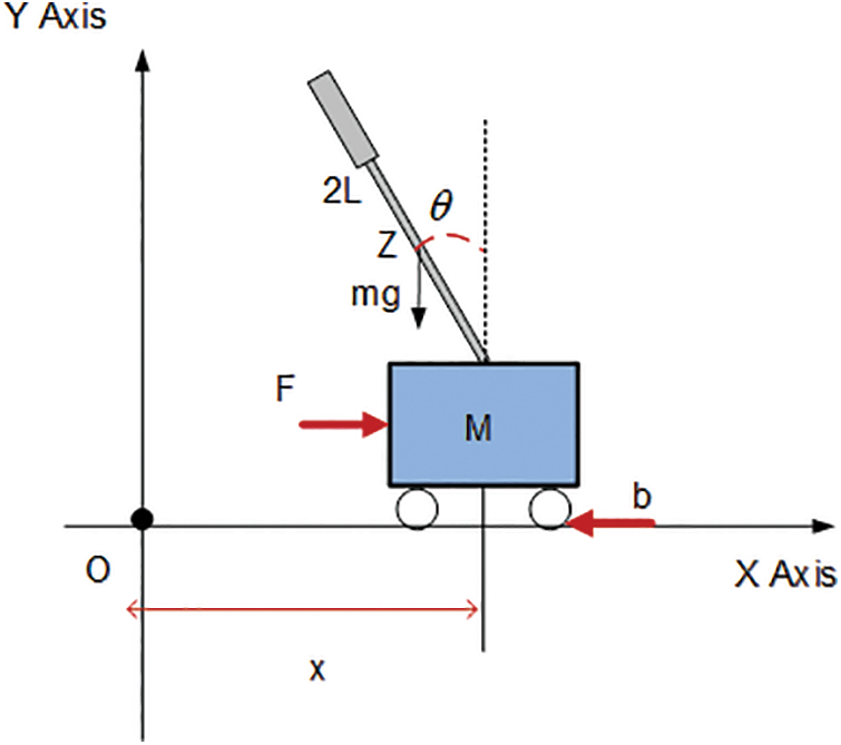
Figure 1: The model of IPS
Here
The mathematical model of the system is constructed as follows in the form of a state-space form
3 Controller Designs for the System
These controllers were created especially for the IPS to maintain the pendulum arms raised and bring the cart to its equilibrium position. IPS was controlled using GWO-based Linear Quadratic Regulator (LQR) and GWO-based Fuzzy Linear Quadratic Regulator (FLQR) control methods. The significant problem in the control of a system is figuring out the optimal control law that reduces the specified performance index to a minimum. The LQR control scheme is one of the optimal control approaches and uses a state-space model of the system [43]. It is a full-state feedback-type controller. The primary goal of optimum control is to overestimate (maximize or minimize) a chosen performance criterion or cost function while simultaneously obtaining control signals that cause a system to satisfy certain physical restrictions. Since the LQR control method is simple, optimal, and robust, it is frequently used in the literature [44–46].
The control’s goal is to reduce the quadratic performance index. The weight matrices are represented by the matrices
The system’s input matrix is shown here by the letter
Various studies have been conducted on how
The GWO algorithm is a population-based meta-heuristic optimization method inspired by the hunting and leadership hierarchy of grey wolves in nature [49]. One of the main advantages of GWO is its dynamic balance between exploration and exploitation. The balance provides more stable results by preventing premature convergence, especially in complex control systems with multiple local minima. Moreover, GWO requires fewer parameters compared to algorithms such as PSO or GA, which reduces the sensitivity of the algorithm to parameter tuning and makes it easier to implement. The GWO algorithm stands out with its better convergence speed and lower error rate, especially in engineering problems that require solutions in continuous space [50–52]. The GWO algorithm has been chosen for optimizing the control parameters in the IPS due to its ability to perform global optimization without the need for gradient information, which is particularly useful for nonlinear systems. While it offers significant advantages, such as better exploration of the solution space compared to traditional optimization methods, its main challenges include computational cost, especially for real-time applications, and sensitivity to parameter settings and initial conditions. Despite these challenges, GWO provides a robust framework for improving the performance of the control system under varying conditions, making it an appropriate choice for the dynamic nature of the IPS. These features provide significant advantages for nonlinear, multivariate problems such as optimization of the LQR gain matrix. In this study, parametric analysis and comparative tests revealed that GWO improves both the control performance and the stability of the system within the Fuzzy-LQR control structure. In this study, the GWO algorithm is used to obtain the boundary values of the
Implementation Steps of GWO-Based LQR and FLQR Methods:
Step 1: Initialization and Parameter Settings
To run the GWO algorithm, initial parameters are described.
Number of iterations: Determines how many generations the GWO algorithm will run for.
Population size: The number of grey wolves (number of solution candidates) is described.
Leadership hierarchy parameters: Alpha, beta, and delta wolves are described as factors that balance the algorithm’s exploration and exploitation capabilities.
Step 2: Creating the Initial Population
In the GWO algorithm, each individual (wolf) is a solution vector representing the gain matrices of the LQR or FLQR controller (e.g., the Q and R matrices or the gains together with the membership function parameters for FLQR). The initial population is generated randomly or according to certain initial conditions.
Step 3: Defining the FLQR and LQR Controller Structure
In this step, classical LQR and Fuzzy-LQR structures are described:
For LQR: The state-feedback structure is created, and the controller is configured via the Q and R matrices.
For FLQR: Input-output variables, fuzzy membership functions (Gauss), and rule bases are created.
Step 4: Optimization Process with GWO
The performance of each solution candidate (i.e., each GWO wolf) is evaluated as follows:
Performance metric: Usually, a cost function (the integral of the time-weighted absolute error (ITAE) is used to minimize the output error of the IPS. The GWO algorithm updates the solution vectors by following the lead wolves and using environmental exploration strategies. The aim is to find the LQR/FLQR parameters that will provide the best control performance.
Step 5: Selecting the Best Solution
At the end of each generation, the solution with the lowest cost function (the best Q-R parameters or FLQR membership functions) is selected. This solution is considered the parameter set that maximizes the control performance of the system.
Step 6: System Test and Evaluation with the Obtained Controller
The optimum LQR or FLQR controller is tested on the IPS system:
The dynamic responses of the system (linear and angular position) are analyzed. The effectiveness of the active control is evaluated by comparative analysis with the IPS system.
Step 7: Conclusion and Development Possibilities
The IPS’s performance is assessed in light of the outcomes. If necessary, further improvements can be made to the GWO algorithm.
The explanation of the time complexity of GWO is given as follows: (a) the time required to initialize GWO is O(N × D), where N is the population size and D is the function size, (b) It takes O(N × D) time to calculate the GWO control parameters, (c) It takes O(N × D) time for GWO’s search agents to update their locations, d) It takes O(N × D) time to evaluate each search agent’s fitness. In conclusion, each generation’s total time complexity is O(N × D). Thus, for the maximum number of iterations, the overall time complexity of GWO is O(N × D × max _iter), where max _iter is the maximum number of iterations. In the LQR and FLQR control methods, the integral of the time-weighted absolute error (ITAE) is used as the objective function (GWO algorithm) to minimize the errors obtained as a result of the system operation.
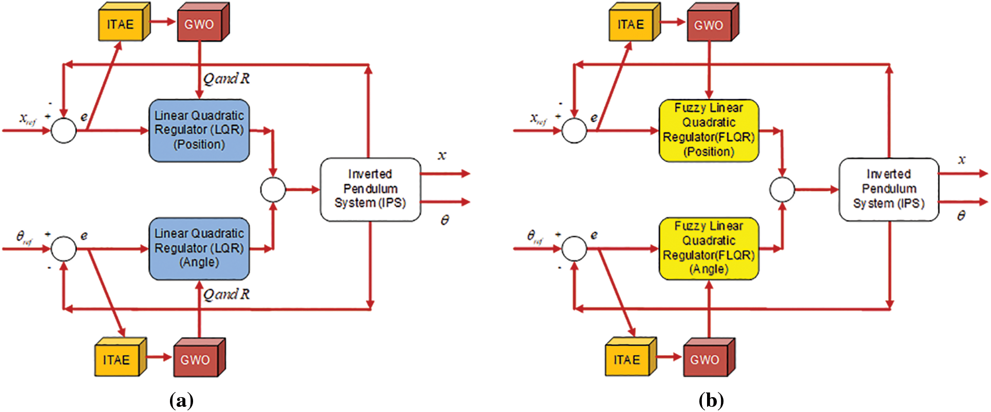
Figure 2: The control methods (a) the LQR, (b) the FLQR block diagram
Fig. 2 illustrates the control diagram of the two methods: (a) LQR and (b) FLQR. As can be seen in both control diagrams, ITAE is used as the objective function for the GWO optimization method. The input values for the controller are the error (
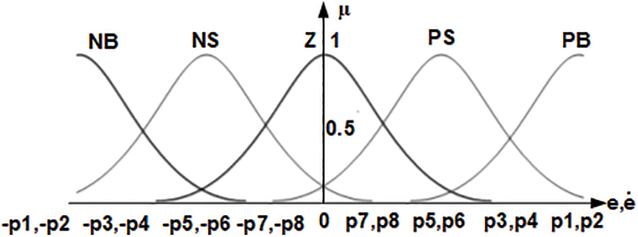
Figure 3: The FLQR membership functions defined for input values
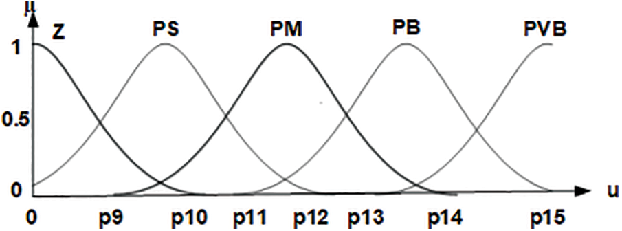
Figure 4: The FLQR membership functions defined for the output value
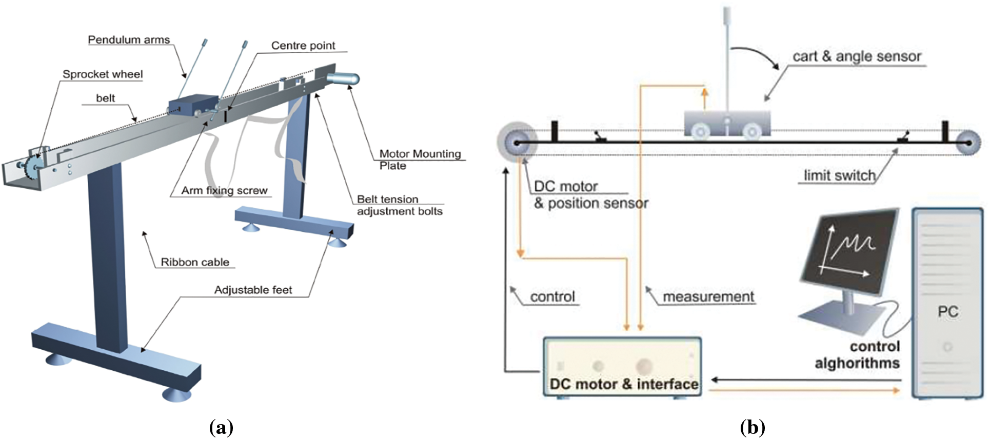
Figure 5: (a) Mechanical representation, (b) Control installation schema of the IPS
Figs. 3 and 4 illustrate the membership functions and boundary values described for the system’s input variables: the error (
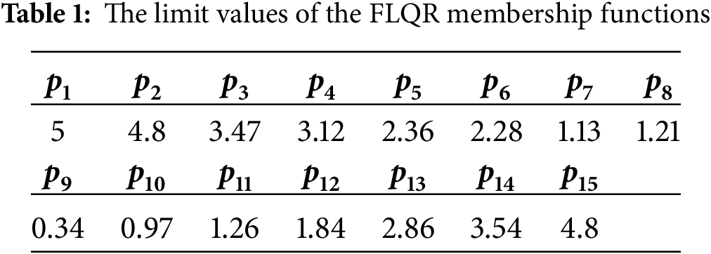
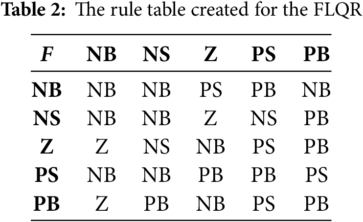
Table 1 presents the boundary values of the membership functions utilized in the FLQR control method, as optimized by the GWO algorithm. These values described the fuzzy partitions for the input and output variables, ensuring accurate fuzzification and defuzzification within the control process. Table 2 displays the fuzzy rule base developed for the FLQR controller. This rule set governs the relationship between the input variables error (
4 Experimental Studies and Results
This section provides experimental studies on the IPS using its dynamic equations. The consequences of the suggested and real-time applied control methods are graphically and numerically presented. Fig. 5 shows (a) the mechanical representation and (b) the control installation schema of the IPS.
The IPS, whose control variables are the position of the cart (
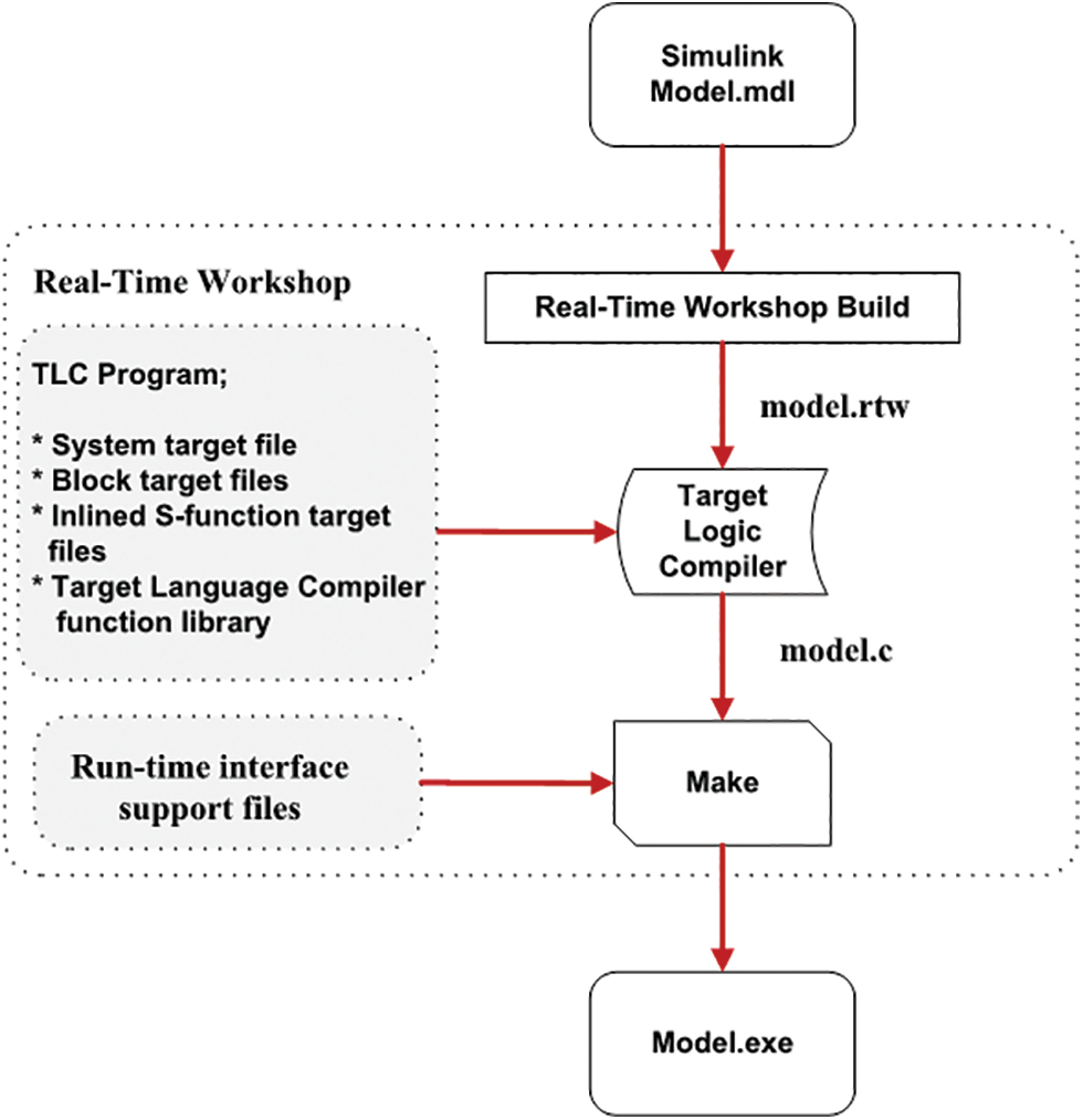
Figure 6: The real-time flow diagram of the IPS
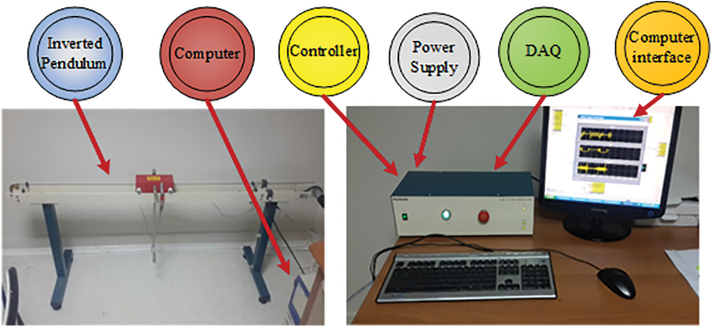
Figure 7: The IPS experimental setup
The physical parameters of IPS are taken as
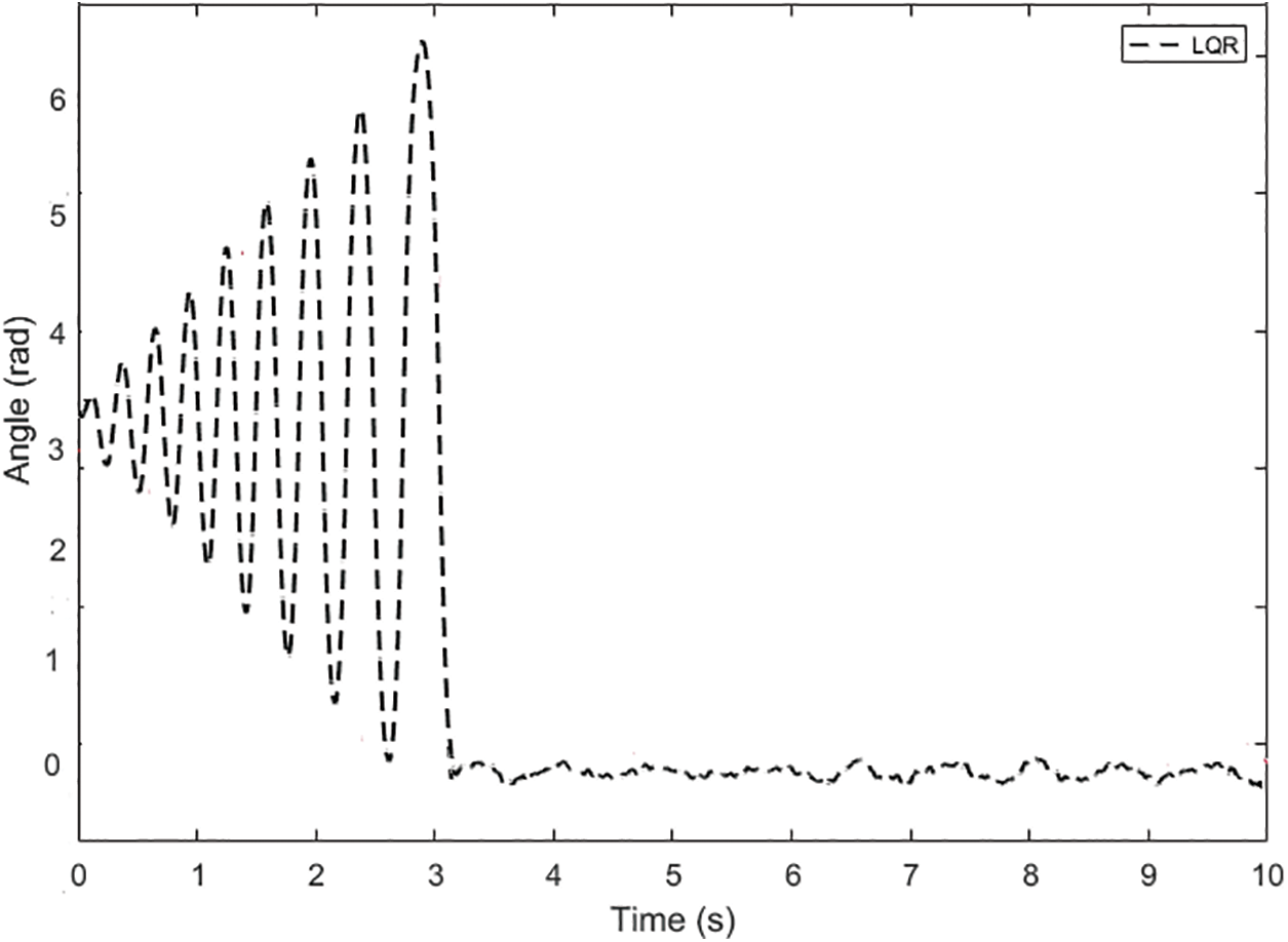
Figure 8: The LQR control method for the pendulum arm angle
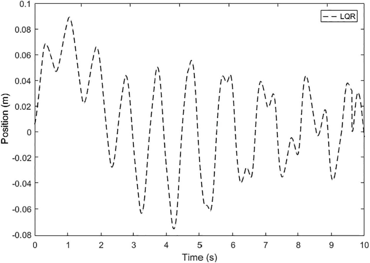
Figure 9: The LQR control method for the position of the cart
When the performance of the LQR controller applied to the arm angle of the pendulum illustrated in Fig. 8 is examined, it is seen that the settling time of the arm angle of the pendulum is 3.1 s, and the peak point is obtained as 6.7 radians. It is also observed that the arm angle of the pendulum continues in the range of ±0.08 radians of oscillation when it reaches the equilibrium position. When the position of the cart shown in Fig. 9 is analyzed, it is seen that it initially started in the oscillation range of +0.09 and −0.078 radians and then continued in the range of approximately ±0.04 radians. The arm angle of the pendulum and the position of the cart using the FLQR controller are shown in Figs. 10 and 11.
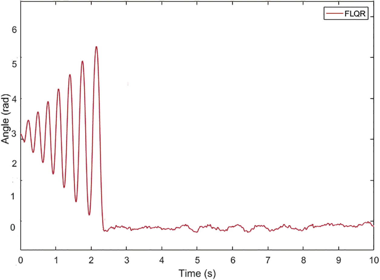
Figure 10: The FLQR control method for pendulum arm angle
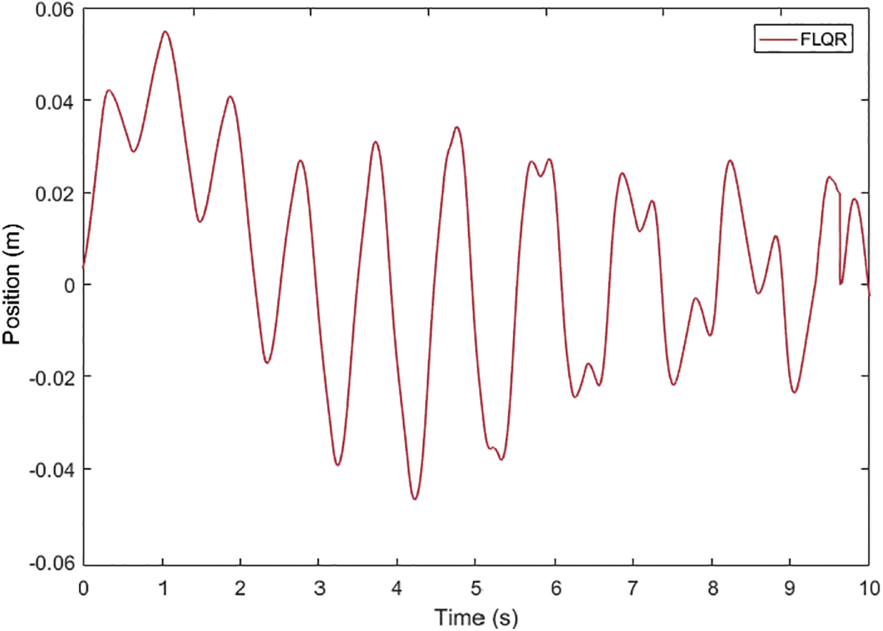
Figure 11: The FLQR control method for the position of the cart
When the performance of the FLQR controller applied to the arm angle of the pendulum illustrated in Fig. 10 is investigated, it is seen that the settling time of the arm angle of the pendulum is 2.4 s, and the peak point is obtained as 5.48 radians. It is observed that the arm angle of the pendulum continues in the oscillation range of ±0.06 radians when it reaches the equilibrium position. When the position of the cart shown in Fig. 11 is analyzed, it is seen that it initially starts in the oscillation range of +0.055 and −0.047 radians and then continues in the range of approximately ±0.025 radians. The comparison graphs of the arm angle of the pendulum and the position of the cart using the LQR and the FLQR controller methods are given in Figs. 12 and 13. The graph for the settling time of the angle value of the pendulum and peak value comparison when the LQR and the FLQR were applied is given in Fig. 14.
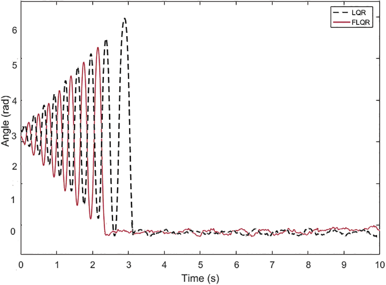
Figure 12: Angle comparison of the pendulum when the LQR and the FLQR type controllers are applied
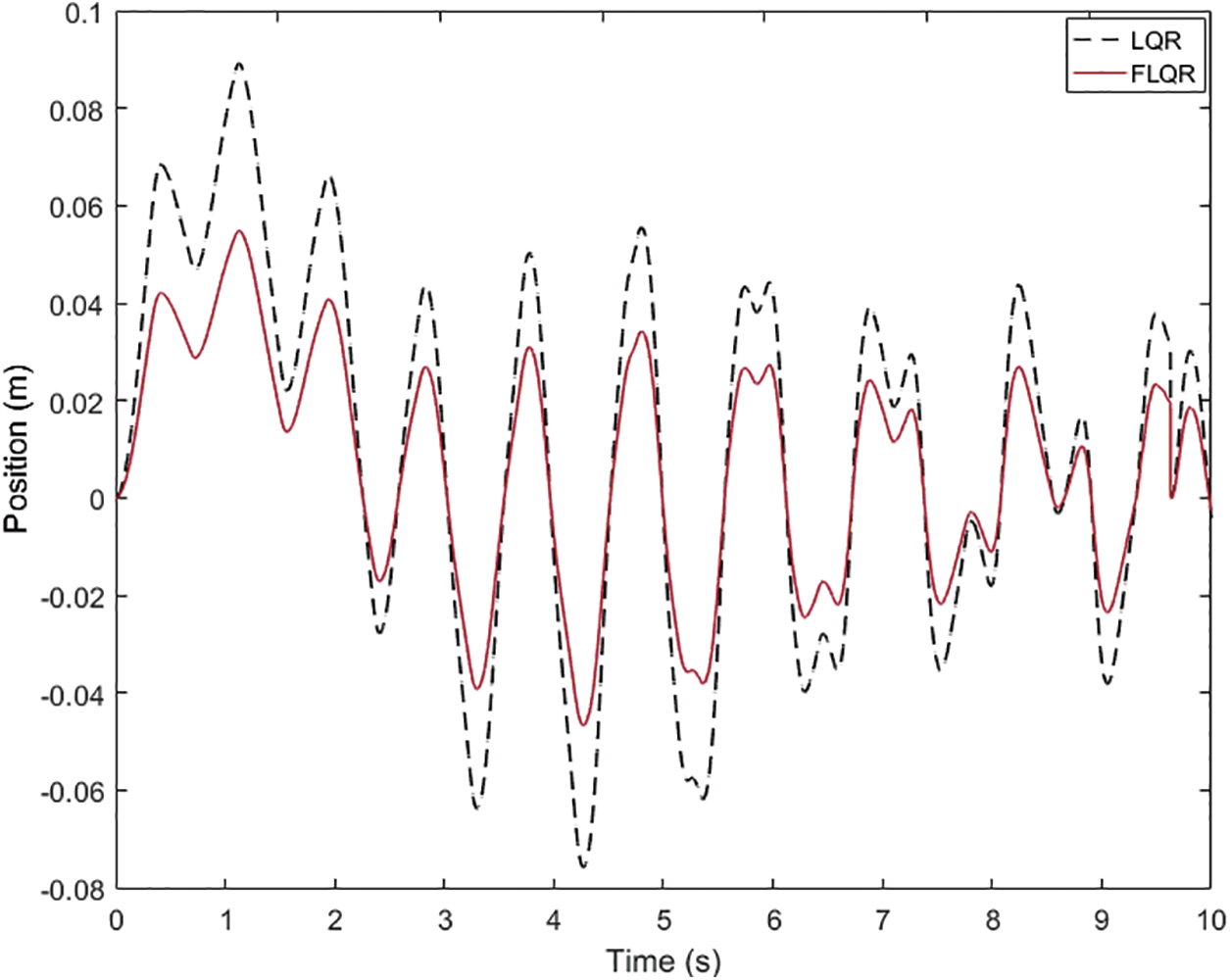
Figure 13: The cart position comparison when the LQR and the FLQR are applied
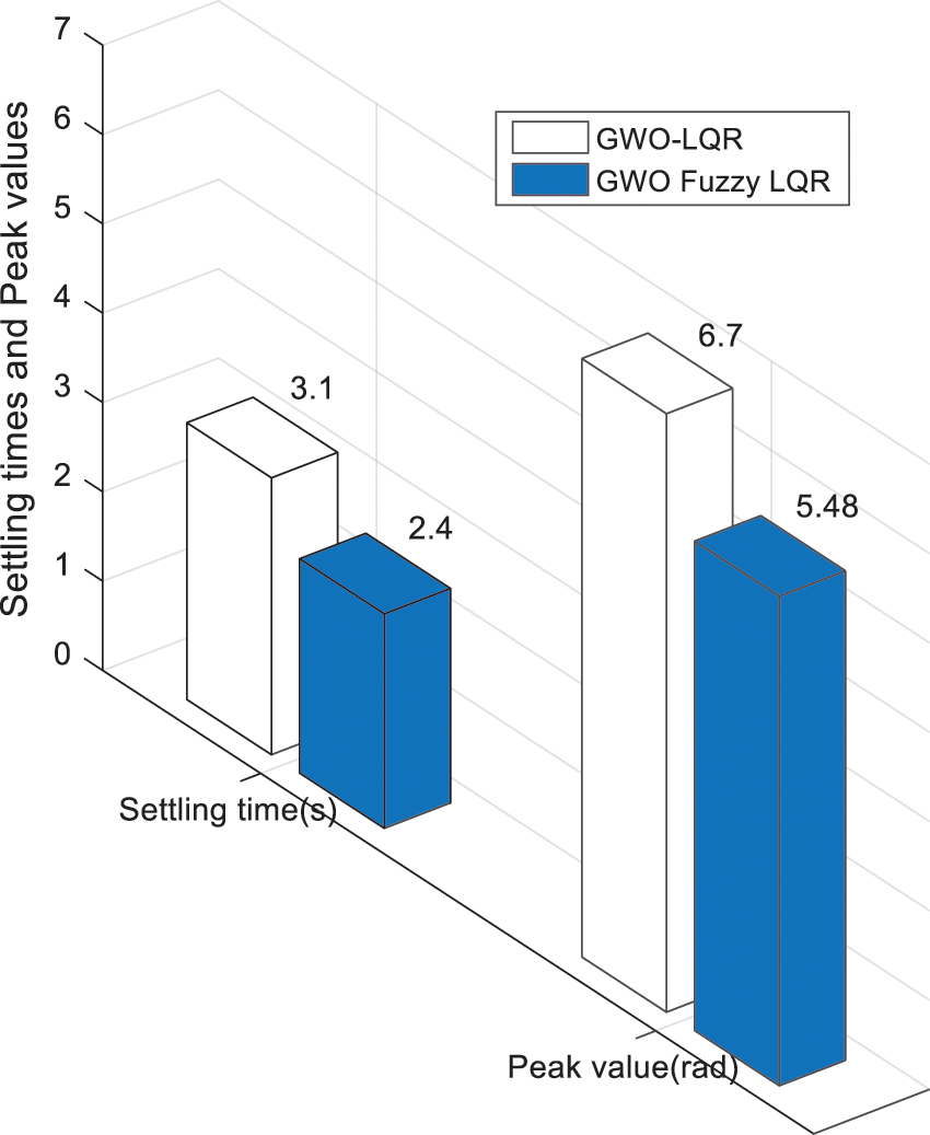
Figure 14: The comparison of the settling time and peak value of the angle value of the pendulum when the LQR and the FLQR are applied
When the comparative pendulum arm angle graphs given in Figs. 12 and 14 are analyzed, it is seen that there is an improvement compared to the LQR control method by decreasing the settling time by 22.58% and the peak value by 18.2% when the FLQR method is used. When the position graph of the cart given in Fig. 13 is analyzed, it is seen that the targeted value of the arms of the pendulum is obtained with shorter position movements from the starting point of the cart when the FLQR method is used. The robustness analysis of the suggested method (GWO-based FLQR) was tested by considering ±10% variations in the mass parameter of the car and the pendulum, and the graph is given in Fig. 15. The suggested control methods’ settling time performance comparison graph with the methods from the literature is indicated in Fig. 16.
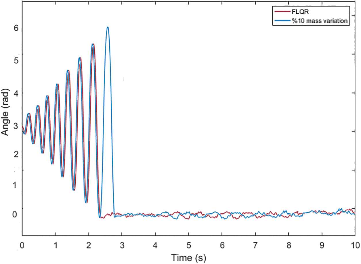
Figure 15: System performance under variation in cart and pendulum mass
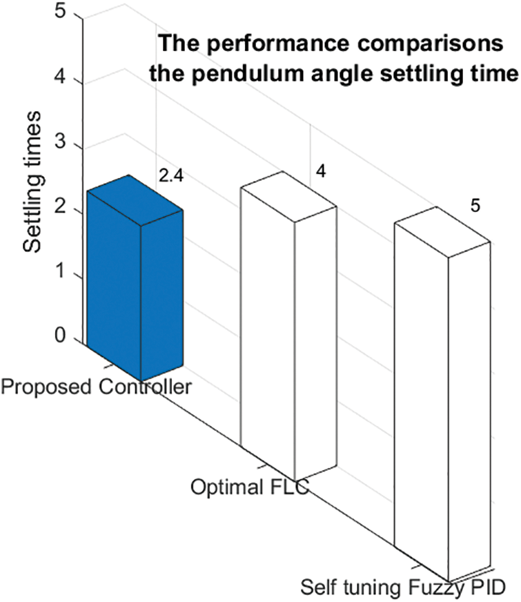
Figure 16: The settling time performance contrasted with the suggested control method with the methods in the literature
The performance of the GWO-based Fuzzy-LQR controller under these conditions (±10% variations in the mass parameter of the trolley and the pendulum) is investigated. The results obtained show that the controller maintains the overall system stability and regulation capability despite being affected to a certain extent, contrasted to the nominal conditions. When the settling time performance of the suggested control method, given in Fig. 16, is analyzed with the methods in the literature, the FLQR control method shows the lowest error arm angle settling time, and its value is 2.4 s. In the real-time control studies enforced in the literature, the arm angle settling time performance was carried out with Self-tuning Fuzzy PID [4] and Optimal Fuzzy Logic [36] methods, and the times were shown as 5 and 4 s, respectively. In light of the aforementioned findings, it is evident that the proposed FLQR control approach performs better in terms of arm angle settling time than previous research in the literature. The following is an expression of this work’s limitations: The GWO’s performance can change, particularly if the system becomes more complex or the parameters are nonlinear. Under specific circumstances, the FLQR approach employed in the study is optimized. Its capacity to continuously adjust to shifting system conditions (such as load or speed) might be constrained, though. In real-time operation, delays caused by sensors, processors, and actuators may adversely influence the stability of the system. The large number of membership functions used in the fuzzy LQR method can also increase the decision time and cause control delay.
In this study, a mathematical model of the IPS was improved, and two control strategies, GWO-optimized LQR and GWO-based FLQR, were designed and implemented to stabilize the system. The controllers were applied in real-time to maintain the pendulum arms in vertical equilibrium while positioning the cart at its reference point. The GWO algorithm was utilized to optimize the LQR’s Q and R parameters, and to tune the membership function boundaries in the FLQR method. Experimental results demonstrated that the FLQR controller outperformed the LQR, achieving a 22.58% reduction in settling time and an 18.2% decrease in peak overshoot. Furthermore, the FLQR method achieved a settling time of 2.4 s, showing superior performance compared to similar studies in the literature. For future work, the suggested FLQR method could be extended to systems with multiple degrees of freedom. Additionally, exploring various optimization techniques, objective functions, membership function types, and rule structures may further enhance control performance.
Acknowledgement: This study was carried out in the Mechanical Theory and Dynamics Laboratory of the Department of Mechanical Engineering, Faculty of Engineering, Fırat University.
Funding Statement: The author received no financial support for the research, authorship, and/or publication of this article.
Availability of Data and Materials: Data available within the article. The author confirms that the data supporting the findings of this study are available within the article.
Ethics Approval: This article does not contain any studies with human participants or animals performed by any of the authors.
Conflicts of Interest: The author declares no conflicts of interest to report regarding the present study.
References
1. Li Y, Jiang Y, Hosoda K. Design and sequential jumping experimental validation of a musculoskeletal bipedal robot based on the spring-loaded inverted pendulum model. Front Rob AI. 2024;11:1296706. doi:10.3389/frobt.2024.1296706. [Google Scholar] [PubMed] [CrossRef]
2. Yang W, Reis J, Yu G, Silvestre C. Output feedback control of an underactuated flying inverted pendulum. Control Eng Pract. 2025;164(8):106474. doi:10.1016/j.conengprac.2025.106474. [Google Scholar] [CrossRef]
3. Shreedharan S, Ravikumar V, Mahadevan SK. Design and control of real-time inverted pendulum system with force-voltage parameter correlation. Int J Dyn Control. 2021;9(4):1672–80. doi:10.1007/s40435-020-00753-5. [Google Scholar] [CrossRef]
4. Abut T, Soyguder S. Real-time control and application with self-tuning PID-type fuzzy adaptive controller of an inverted pendulum. Ind Robot. 2019;46(1):159–70. doi:10.1108/ir-10-2018-0206. [Google Scholar] [CrossRef]
5. Hazem ZB, Bingül Z. Comprehensive review of different pendulum structures in engineering applications. IEEE Access. 2023;11:42862–42880. doi:10.1109/access.2023.3269580. [Google Scholar] [CrossRef]
6. Pal AK, Oveisi A, Nestorović T. The effect of model uncertainties in the reinforcement learning based regulation problem: an experimental case study with inverted pendulum. PAMM. 2023;23(4):e202300130. doi:10.1002/pamm.202300130. [Google Scholar] [CrossRef]
7. Zadeh LA. Fuzzy logic. Computer. 1988;21(4):83–93. [Google Scholar]
8. Hung CC, Fernandez RB. Comparative analysis of control design techniques for a cart-inverted pendulum in real-time implementation. In: 1993 American Control Conference. San Francisco, CA, USA: IEEE; 1993. p. 1870–4. [Google Scholar]
9. Sáez D, Cipriano A. Fuzzy linear quadratic regulator applied to the real-time control of an inverted pendulum. IFAC Proc Vol. 1998;31(4):155–60. doi:10.1016/s1474-6670(17)42150-1. [Google Scholar] [CrossRef]
10. Chen CS, Chen WL. Robust adaptive sliding-mode control using fuzzy modeling for an inverted-pendulum system. IEEE Trans Ind Electron. 1998;45(2):297–306. doi:10.1109/41.681229. [Google Scholar] [CrossRef]
11. Magana ME, Holzapfel F. Fuzzy-logic control of an inverted pendulum with vision feedback. IEEE Trans Educ. 1998;41(2):165–70. doi:10.1109/13.669727. [Google Scholar] [CrossRef]
12. Teng FC. Real-time control using Matlab Simulink. In: SMC 2000 Conference Proceedings. 2000 IEEE International Conference on Systems, Man, and Cybernetics. Cybernetics Evolving to Systems, Humans, Organizations, and Their Complex Interactions. Nashville, TN, USA: IEEE; 2000. Vol. 4, p. 2697–702. [Google Scholar]
13. Nundrakwang S, Benjanarasuth T, Ngamwiwit J, Komine N. Hybrid controller for swinging up inverted pendulum system. In: 2005 5th International Conference on Information Communications & Signal Processing. Bangkok, Thailand: IEEE; 2005. p. 488–92. [Google Scholar]
14. Muskinja N, Tovornik B. Swinging up and stabilization of a real inverted pendulum. IEEE Trans Ind Electron. 2006;53(2):631–9. doi:10.1109/tie.2006.870667. [Google Scholar] [CrossRef]
15. Gawthrop PJ, Wang L. Intermittent predictive control of an inverted pendulum. Control Eng Pract. 2006;14(11):1347–56. doi:10.1016/j.conengprac.2005.09.002. [Google Scholar] [CrossRef]
16. Chen X, Zhou H, Ma R, Zuo F, Zhai G, Gong M. Linear motor-driven inverted pendulum and LQR controller design. In: 2007 IEEE International Conference on Automation and Logistics. Jinan, China: IEEE; 2007. p. 1750–4. [Google Scholar]
17. Lee GH, Jung S. Control of inverted pendulum system using a neuro-fuzzy controller for intelligent control education. In: 2008 IEEE International Conference on Mechatronics and Automation. Takamatsu, Japan: IEEE; 2008. p. 965–70. [Google Scholar]
18. Hu LY, Liu GP, Liu XP, Zhang H. The computer simulation and real-time stabilization control for the inverted pendulum system based on LQR. In: 2009 Fifth International Conference on Natural Computation. Tianjian, China: IEEE; 2009. Vol. 6. p. 438–42. [Google Scholar]
19. Liu Y, Chen Z, Xue D, Xu X. Real-time controlling of inverted pendulum by fuzzy logic. In: 2009 IEEE International Conference on Automation and Logistics. Shenyang, China: IEEE; 2009. p. 1180–3. [Google Scholar]
20. Kizir S, Bingul Z, Oysu C. Fuzzy control of a real-time inverted pendulum system. J Intell Fuzzy Syst. 2010;21(1,2):121–33. [Google Scholar]
21. Hamza M, Zahid Q, Tahir F, Khalid Z. Real-time control of an inverted pendulum: a comparative study. In: 2011 Frontiers of Information Technology. Islamabad, Pakistan: IEEE; 2011. p. 183–8. [Google Scholar]
22. Xin Y, Xu B, Xin H, Xu J, Hu L. The computer simulation and real-time control for the inverted pendulum system based on PID. In: 2011 International Conference on Electric and Electronics (EEIC 2011); 2011 Jun 20–22; Nanchang, China;2011. Vol. 4, p. 729–36. [Google Scholar]
23. Kumar EV, Jerome J. Robust LQR controller design for stabilizing and trajectory tracking of inverted pendulum. Procedia Eng. 2013;64:169–78. doi:10.1016/j.proeng.2013.09.088. [Google Scholar] [CrossRef]
24. Durand S, Castellanos FG, Marchand N, Sánchez WFG. Event-based control of the inverted pendulum: swing up and stabilization. J Control Eng Appl Inf. 2013;15(3):96–104. [Google Scholar]
25. Urniezius R, Geguzis E. Hybrid fuzzy logic and adaptive LQR controller for swing-up, positioning and stabilization of inverted pendulum. Elektron Elektrotech. 2014;20(3):11–5. doi:10.5755/j01.eee.20.3.6675. [Google Scholar] [CrossRef]
26. Bettayeb M, Boussalem C, Mansouri R, Al-Saggaf UM. Stabilization of an inverted pendulum-cart system by fractional PI-state feedback. ISA Trans. 2014;53(2):508–16. doi:10.1016/j.isatra.2013.11.014. [Google Scholar] [PubMed] [CrossRef]
27. Singla A, Singh G. Real-time swing-up and stabilization control of a cart-pendulum system with constrained cart movement. Int J Nonlinear Sci Numer Simul. 2017;18(6):525–39. doi:10.1515/ijnsns-2017-0040. [Google Scholar] [CrossRef]
28. Su X, Xia F, Liu J, Wu L. Event-triggered fuzzy control of nonlinear systems with its application to inverted pendulum systems. Automatica. 2018;94(6):236–48. doi:10.1016/j.automatica.2018.04.025. [Google Scholar] [CrossRef]
29. Du D, Zhang C, Song Y, Zhou H, Li X, Fei M, et al. Real-time H∞ control of networked inverted pendulum visual servo systems. IEEE Trans Cybern. 2019;50(12):5113–26. doi:10.1109/tcyb.2019.2921821. [Google Scholar] [PubMed] [CrossRef]
30. Tiga A, Ghorbel C, Benhadj Braiek N. Nonlinear/linear switched control of inverted pendulum system: stability analysis and real-time implementation. Math Probl Eng. 2019;2019(1):391587. doi:10.1155/2019/2391587. [Google Scholar] [CrossRef]
31. Kennedy E, King E, Tran H. Real-time implementation and analysis of a modified energy-based controller for the swing-up of an inverted pendulum on a cart. Eur J Control. 2019;50(6):176–87. doi:10.1016/j.ejcon.2019.05.002. [Google Scholar] [CrossRef]
32. Blondin MJ, Pardalos PM. A holistic optimization approach for inverted cart-pendulum control tuning. Soft Comput. 2020;24(6):4343–59. doi:10.1007/s00500-019-04198-7. [Google Scholar] [CrossRef]
33. Susanto E, Wibowo AS, Rachman EG. Fuzzy swing up control and optimal state feedback stabilization for self-erecting inverted pendulum. IEEE Access. 2020;8:6496–6504. doi:10.1109/access.2019.2963399. [Google Scholar] [CrossRef]
34. Waszak M, Łangowski R. An automatic self-tuning control system design for an inverted pendulum. IEEE Access. 2020;8:26726–26738. doi:10.1109/access.2020.2971788. [Google Scholar] [CrossRef]
35. Llama M, Flores A, Garcia-Hernandez R, Santibañez V. Heuristic global optimization of an adaptive fuzzy controller for the inverted pendulum system: experimental comparison. Appl Sci. 2020;10(18):6158. doi:10.3390/app10186158. [Google Scholar] [CrossRef]
36. Jain A, Sharma A, Jately V, Azzopardi B, Choudhury S. Real-time swing-up control of non-linear inverted pendulum using Lyapunov based optimized fuzzy logic control. IEEE Access. 2021;9:50715–50726. doi:10.1109/access.2021.3058645. [Google Scholar] [CrossRef]
37. Ping Z, Zhou M, Liu C, Huang Y, Yu M, Lu JG. An improved neural network tracking control strategy for linear motor-driven inverted pendulum on a cart and experimental study. Neural Comput Appl. 2022;34(7):5161–8. doi:10.1007/s00521-021-05986-9. [Google Scholar] [CrossRef]
38. Mondal R, Dey J. A novel design methodology on cascaded fractional order (FO) PI-PD control and its real time implementation to cart-inverted pendulum system. ISA Trans. 2022;130(17):565–81. doi:10.1016/j.isatra.2022.04.015. [Google Scholar] [PubMed] [CrossRef]
39. Israilov S, Fu L, Sánchez-Rodríguez J, Fusco F, Allibert G, Raufaste C, et al. Reinforcement learning approach to control an inverted pendulum: a general framework for educational purposes. PLoS One. 2023;18(2):e0280071. doi:10.1371/journal.pone.0280071. [Google Scholar] [PubMed] [CrossRef]
40. Liu X, Wang S, Li X, Cui Z. Balance controller design for inverted pendulum considering detail reward function and two-phase learning protocol. Symmetry. 2024;16(9):1227. doi:10.3390/sym16091227. [Google Scholar] [CrossRef]
41. Tian B, Peng H, Kang T. RBF-ARX model-based predictive control approach to an inverted pendulum with self-triggered mechanism. Chaos Soliton Fract. 2024;186(1):115291. doi:10.1016/j.chaos.2024.115291. [Google Scholar] [CrossRef]
42. Bajrami X, Kaçiu F, Shala E, Likaj R. Real-time swing-up of a linear inverted pendulum using reinforcement learning. Mech. 2025;31(2):123–35. doi:10.5755/j02.mech.39202. [Google Scholar] [CrossRef]
43. Anderson BD, Moore JB. Optimal control: linear quadratic methods. Chelmsford, MA, USA: Courier Corporation; 2007. [Google Scholar]
44. Sun Y, Xian N, Duan H. Linear-quadratic regulator controller design for quadrotor based on pigeon-inspired optimization. Aircr Eng Aerosp Technol. 2016;88(6):761–70. doi:10.1108/aeat-03-2015-0088. [Google Scholar] [CrossRef]
45. Abut T, Salkim E. Control of quarter-car active suspension system based on optimized fuzzy linear quadratic regulator control method. Appl Sci. 2023;13(15):8802. doi:10.3390/app13158802. [Google Scholar] [CrossRef]
46. Abut T. Optimal LQR controller methods for double inverted pendulum system on a cart. Dicle Üniversitesi Müh Fakültesi Müh Derg. 2023;14(2):247–55. [Google Scholar]
47. Begum B, Jena NK, Sahu BK, Bajaj M, Blazek V, Prokop L. Frequency stability improvement in EV-integrated power systems using optimized fuzzy-sliding mode control and real-time validation. Sci Rep. 2025;15(1):5782. doi:10.1038/s41598-025-89025-w. [Google Scholar] [PubMed] [CrossRef]
48. de la Cruz-Alejo J, Beatriz-Cuellar H, Guillermo IA, Ortega AM. A decision-making approach on control techniques for an inverted pendulum based on, neuro-fuzzy, indirect adaptive and PID controllers. Discov Appl Sci. 2024;6(5):251. doi:10.1007/s42452-024-05921-2. [Google Scholar] [CrossRef]
49. Mirjalili S, Mirjalili SM, Lewis A. Grey wolf optimizer. Adv Eng Softw. 2014;69:46–61. doi:10.1016/j.advengsoft.2013.12.007. [Google Scholar] [CrossRef]
50. Dhiman G, Kumar V. A novel and comprehensive review of the GWO algorithm. Artif Intell Rev. 2017;53(6):4111–53. [Google Scholar]
51. Abut T, Salkım E, Demosthenous A. Performance improvement in a vehicle suspension system with FLQG and LQG control methods. Actuators. 2025;14(3):1–16. [Google Scholar]
52. Saremi S, Mirjalili S, Lewis A. How a grey wolf thinks: tracking the leadership hierarchy. Appl Soft Comput. 2017;60:245–54. [Google Scholar]
Cite This Article
 Copyright © 2025 The Author(s). Published by Tech Science Press.
This work is licensed under a Creative Commons Attribution 4.0 International License , which permits unrestricted use, distribution, and reproduction in any medium, provided the original work is properly cited.
 Downloads
 Citation Tools