
 Submit a Paper
 Propose a Special lssue
 Open Access
ARTICLE

Flatness Control with Cascaded Filtered High-Gain and Disturbance Observers for Rehabilitation Exoskeletons
1 Department of Computer and Network Engineering, College of Computer Science and Engineering, University of Jeddah, Jeddah, 21959, Saudi Arabia
2 King Salman Center for Disability Research, Riyadh, 11614, Saudi Arabia
3 National Engineers School of Monastir, University of Monastir, Monastir, 5000, Tunisia
* Corresponding Author: Sahbi Boubaker. Email:
Computers, Materials & Continua 2025, 85(3), 5703-5721. https://doi.org/10.32604/cmc.2025.069047
Received 13 June 2025; Accepted 22 August 2025; Issue published 23 October 2025
 View Full Text
 Download PDF
Abstract
Accurate trajectory tracking in lower-limb exoskeletons is challenged by the nonlinear, time-varying dynamics of human-robot interaction, limited sensor availability, and unknown external disturbances. This study proposes a novel control strategy that combines flatness-based control with two cascaded observers: a high-gain observer to estimate unmeasured joint velocities, and a nonlinear disturbance observer to reconstruct external torque disturbances in real time. These estimates are integrated into the control law to enable robust, state-feedback-based trajectory tracking. The approach is validated through simulation scenarios involving partial state measurements and abrupt external torque perturbations, reflecting realistic rehabilitation conditions. Results confirm that the proposed method significantly enhances tracking accuracy and disturbance rejection capability, demonstrating its strong potential for reliable and adaptive rehabilitation assistance.Keywords
Exoskeletons are wearable mechanical structures designed to support, enhance, or restore human movement. They typically consist of rigid frames and joints aligned with the body of the wearing individual, along with sensors, actuators, and control systems that assist or replicate natural human motion. Robotic exoskeleton systems, particularly those designed to help stroke or spinal cord injury patients regain mobility during rehabilitation exercises, are subject to highly nonlinear dynamics and strong interaction between the patient and the exoskeleton [1,2]. In this context, they play a crucial role in supporting physiotherapists and enabling the precise implementation of special movement trajectories tailored to individual patient rehabilitation needs, depending on the subject and the rehabilitation stage. Therefore, the problem of trajectory tracking remains a challenge in the design and control of exoskeletons. It constitutes a hot topic for several research efforts aimed at obtaining accurate regulation of wearable exoskeleton devices, specifically in environments where user participation and uncertainties are significant [3].
This topic has attracted increasing interest over the last two decades. For example, studies conducted in [4,5] concern an upper limb orthosis with two links that perform shoulder and elbow articulations, joined by a hinge joint. Recent work has focused on the development of exoskeletons designed to support upper and lower extremity rehabilitation for people with disabilities [6]. These devices can be applied in various contexts, such as post-injury rehabilitation [7]. Rapid restoration of independence for patients with upper limb impairments is essential, given their crucial involvement in a variety of daily activities [8].
The modeling of an exoskeleton composed of multiple joints involves geometric, kinematic, and time-varying parameters to describe its motion in detail [9]. Moreover, robotic exoskeleton systems are subject to unpredictable exogenous disturbances (contact with the environment, friction, muscle irregularities) [2]. The state model includes a lumped disturbance that includes unknown dynamics and interaction torques applied by the wearer [10,11]. The lumped uncertainty of the brace may depend on the position and velocity of the joints and even on the acceleration signal in the case when it is involved in the control input [12].
In this context, disturbances can seriously degrade the quality of trajectory tracking if they are not taken into account [13]. Effectively managing these non-linear and uncertain aspects in the design and accurate control of the exoskeleton represents a major challenge [7,11,14]. Friction, for example, can have various origins and contribute to energy loss and performance degradation, affecting movement precision and user comfort [14]. Uncompensated friction can cause significant errors that affect the accuracy and performance of robotic systems [9]. Modeling the variation of dry friction as a function of load is often neglected, which can cause problems when robots encounter significant variations in load [15]. In [16], the impact of load on friction forces has been highlighted, which requires consideration for a more accurate model. Moreover, human-robot interaction generally introduces significant unpredictable dynamic uncertainties [17].
Real-time estimation of disturbances may help compensate for their effects through the control law [13]. It also helps to improve controller robustness without having to resort to very high gains, to guarantee better safety of human-robot interaction, and to ensure accurate tracking even in the presence of variable external forces [13,18].
The estimation and detection of anomalies, including external forces, are active areas of research that require the design of observers [19]. Disturbance observers offer a computationally efficient solution for robotic exoskeletons, enabling rapid and precise estimation of unknown forces and/or torques [20]. Among the approaches for observation schemes adopted for exoskeleton systems, the Extended State Observer (ESO) has mainly been used to estimate specific disturbances and compensate for them using a feed-forward cancellation mechanism [21–25]. In [26], the authors showed that ESO-based controllers have significant disturbance rejection capabilities. In addition, the sliding mode control (SMC) technique, known for its robustness to parameter variations and external disturbances, is combined with a disturbance observer to compensate disturbance effects [1,22,27]. The integration of the disturbance observer allows for lower switching gains in the SMC law, thereby significantly reducing chattering. Disturbance observers employing a Kalman filter are exploited to estimate in real-time the disturbance torques affecting the joints, allowing additional terms to be included in the differential flatness-based controller to eliminate the impact of disturbances and ensure accurate tracking [28]. ESO-based robust non-singular adaptive terminal sliding mode control (ATSMC) is proposed for two-link upper limb exoskeletons, incorporating a boundary layer control law [5]. The ATSMC employs an adaptive control strategy to estimate specific types of uncertainties in real time and modify the control input accordingly [11]. This enables the control system to adjust to varying dynamics, guaranteeing rapid finite-time convergence and enhancing tracking accuracy.
From the above literature review, prior studies were often found to be constrained by key assumptions such as full-state availability, limited capacity to manage several types of external disturbances, and reduced robustness in dynamic rehabilitation environments. These challenges have led to the development of our observer-enhanced flatness-based control approach, designed to deliver accurate trajectory tracking under partial measurements and a wide range of external disturbances.
This study aims to ensure accurate trajectory tracking for a 2 DoFs lower limb exoskeleton, which is an essential aspect of rehabilitation, while handling the system’s nonlinear characteristics, uncertainties, and external disturbances. To address this, a novel control structure is proposed, combining a flatness control law with both cascade observers for state and disturbance estimation. The first observer provides an estimation of unmeasured states, while the second downstream observer reconstructs torque disturbances. Simulation results highlight the scheme’s capability to handle abrupt disturbance torques using only available real-time state information. The main contributions of this study are summarized as follows:
• Design of a flatness-based control scheme tailored for a 2-DoF lower-limb exoskeleton, which addresses the nonlinear and time-varying dynamics typically encountered in rehabilitation applications.
• Development of a cascaded observer structure composed of an HGO for estimating unmeasured joint velocities, and a nonlinear DO to reconstruct external torque disturbances in real time.
• Integration of the estimated states and disturbances into the flatness control law, enabling real-time compensation of model uncertainties and human-exoskeleton interaction effects.
• Proof of robust tracking performance through simulations, even under sudden and significant external perturbations, using only partially measured state information.
The remaining structure of this paper is organized as follows: Section 2 presents the nonlinear dynamic model of the 2-DOF exoskeleton system, along with its state-space representation and the main control objective. Section 3 introduces the concept of a disturbance observer and provides a convergence proof based on a Lyapunov function. Section 4 focuses on the design of a flatness-based feedback control law incorporating disturbance compensation. The steps for generating the control law and theoretical analysis of the dynamic tracking error are detailed in Section 5. Section 6 is dedicated to simulation results, including different scenarios, and discusses the tracking performances and disturbance rejection capability of several control schemes. Finally, the conclusion summarizes the contributions and highlights the key features of the proposed control strategy.
2 Exoskeleton Dynamical Modeling
The motion of an
with:
where
For analytical convenience, it is assumed that the derivative of
The matrix
We consider the two DoFs lower limb robotic exoskelelton
where
2.1 State Space Modeling of 2-
The schematic of the
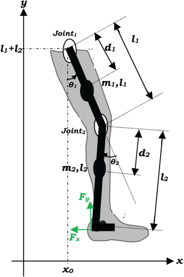
Figure 1: Schematic of the
Let
By referring to (1), one can extract
By differentiating the vector
where
2.2 Torque Transfer at the Robotic Exoskeleton Joint
The reference trajectories of the exoskeleton mechanical structure illustrated in Fig. 1 are given in the Cartesian coordinates as follows:
where
with:
Using a Taylor series expansion, the time delay in the contact forces is approximated as:
The torques transmitted to the joint of the robotic exoskeleton are obtained by:
Achieving robust tracking control in the exoskeleton system under study necessitates estimating unmeasured states, such as angular velocities, and reconstructing unknown disturbances. This is essential to ensure real-time hardware implementation. As is well known, the exoskeleton dynamics are nonlinear and coupled, with the presence of unknown external torques. Since only joint angles are available for feedback, the controller must operate under partial state feedback while ensuring robust performance against unknown disturbances, including external load torques. Conventional observers, such as Luenberger or Kalman filters, along with PID controllers, often fall short in providing finite-time convergence and sufficient robustness in the presence of such disturbances.
To tackle these challenges, we propose a control architecture that combines both cascaded observers with a flatness controller. First, a High Gain Observer (HGO) is developed to estimate unmeasured angular velocity states using only joint angle measurements. Next, a Disturbance Observer (DO) is designed to estimate external load torques, which are modeled as unknown disturbances, based on the angular velocity estimates provided by the HGO. This observer is chosen for its ability to achieve finite-time convergence under bounded disturbances without requiring signal derivatives. Additionally, its simplicity and numerical implementability make it well-suited for embedded real-time applications. Finally, a flatness-based Controller utilizes the estimated states and disturbances to compute the control law. The estimated disturbances are employed to compensate for unknown inputs, including external load torques. This control strategy is selected for its strong robustness and seamless integration with the proposed cascade of observers. Importantly, it avoids complex high-order or backstepping designs, which are more difficult to implement in embedded systems. Fig. 2 illustrates the proposed cascaded observer-based flatness control scheme for the 2-DOF lower-limb exoskeleton, accounting for perturbations from external load torques.
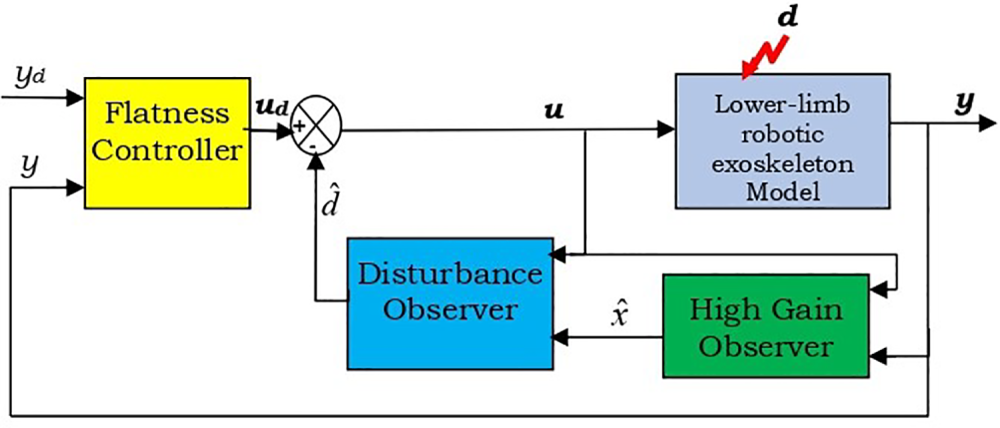
Figure 2: Block diagram of the proposed control architecture
Robust control performance relies heavily on the accurate estimation of the lumped disturbance. This section presents the design procedure of the disturbance observer along with a detailed convergence analysis.
3.1 Disturbance Observer Equations
Accurate estimation of the lumped disturbance is critical for achieving precise control performance. A disturbance observer is used to estimate the disturbance torque vector
where
Note that, similar to the
At this stage, we are interested in designing a disturbance observer capable to estimate unknown torque disturbances
Referring to Eq. (10), the expressions for these torque disturbances can be derived as follows:
Recall that
where
Theorem 1: Consider the system (10) and the observer (12), the estimation error converges to a bounded limit, which can be arbitrarily minimized by the choice of design parameters
The analysis of the convergence of disturbance estimation error is detailed in the next subsection.
3.2 Convergence Proof of the Disturbance Observation Error
Proof of Theorem 1: Let:
After a time derivation and referring to (12), one obtains:
with the same approach, you can have:
Let’s generalize:
The solution of (13) is given as follows:
It arises the following inequality:
It is shown that for large values of design parameters
where
Note that for reconstruction of the original disturbance vector
4 Flatness Feedback Control Law with Disturbance Compensation
In this section, the design procedure of the state feedback controller is presented. Let new state variables
In [30], it is demonstrated that the robotic system is differentially flat, allowing for the design of a stabilizing feedback controller as follows:
when substituting (19) in (2), one obtains:
by referring to (15) and (16), it arrives that:
As detailed in the above section and by referring to (16), after a brief transient time, we have:
with
Then, it suffices to select
5 Cascade Observers Based Flatness Control
In the previous section, it was assumed that all state variables were fully measurable. However, in practical applications, certain states may be inaccessible or require prohibitively expensive sensors for measurement. This motivates the development of a more realistic control architecture, which incorporates not only a disturbance observer but also a state observer to provide an estimation of unmeasured states.
The state model (10) can be rewritten as:
where
In a condensed form, Eq. (24) can be rewritten as follows:
where
A high gain observer (HGO) corresponding to (25) is given by [31]:
where
Note that when all eigenvalues are assigned the value
Accordingly, Eq. (26) can be rewritten in its expanded form as:
Accordingly, the flatness control output feedback law is reformulated as the following expression:
with:
and
6.1 Tracking without Considering Torque Disturbances
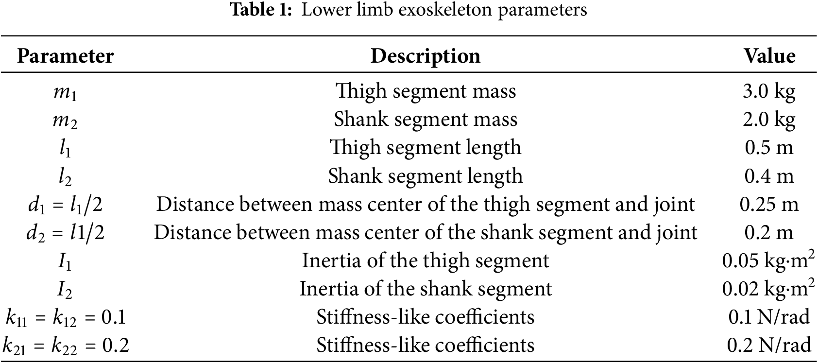
We applied the control law (18) and (19) to the dynamic model of the 2-DoFs exoskeleton described by Eq. (10) with nominal parameters given in Table 1.
In the first simulation scenario, full access to all state variables is assumed. The reference gait trajectories are defined as:
The initial conditions for the two-link human–exoskeleton system are set as:
To reduce the number of parameters
For this first scenario, the prediction horizon is set to:
To evaluate the tracking performance in the presence of disturbances, two load torques were introduced at time
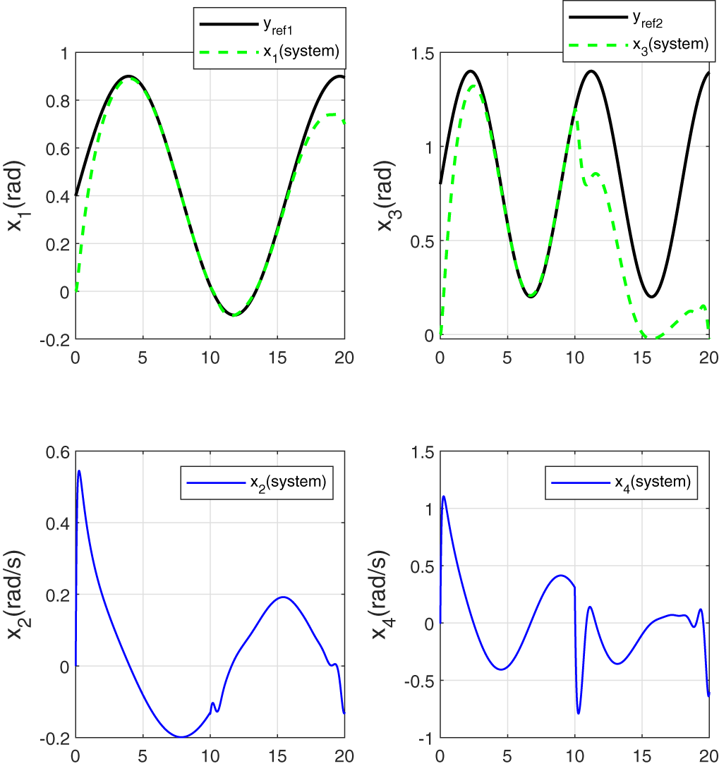
Figure 3: Tracking performance for joint angles without taking into account the disturbance variation in the control law
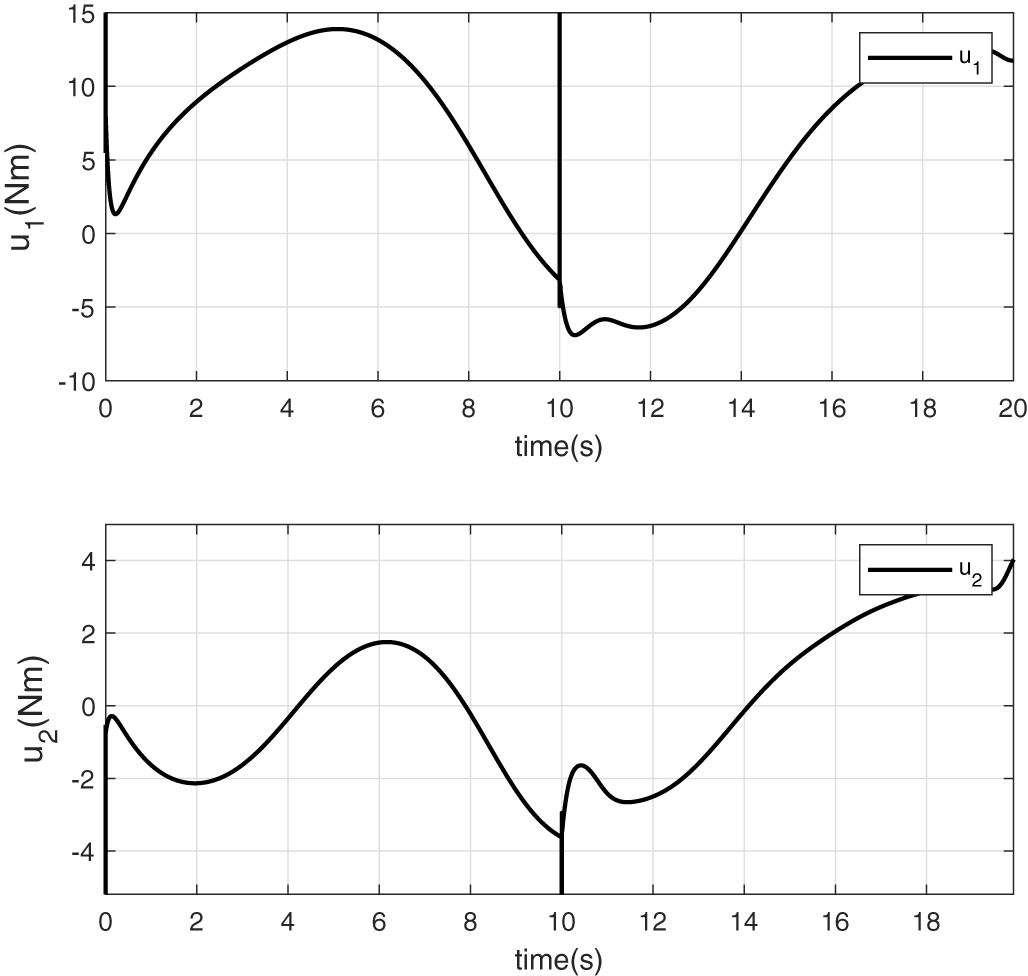
Figure 4: Control torques generated by the control law
It is noteworthy that from the moment the disturbance torques are applied, the tracking objective is no longer achieved. Indeed, the control law generated by the controller is based on the nominal model (without accounting for disturbances).
6.2 Reference Tracking with Consideration of the Disturbance Estimation
The disturbance estimate
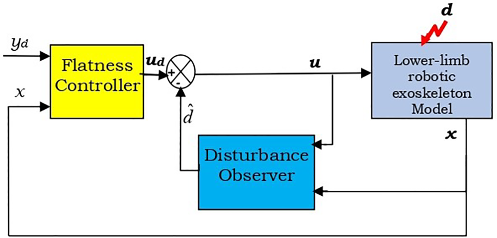
Figure 5: Flatness control structure based on disturbance observer
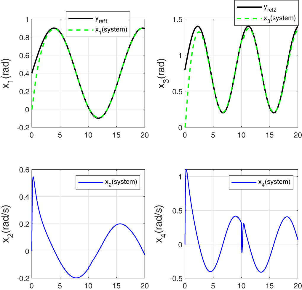
Figure 6: Tracking performance for joint angles with incorporation of the disturbance estimation in the control law
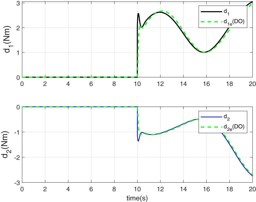
Figure 7: Disturbance torques estimation
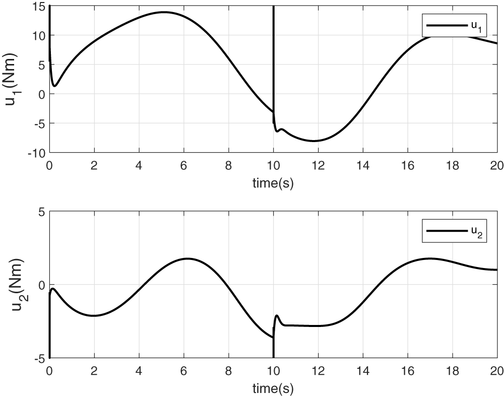
Figure 8: Torque control signals updated with the disturbance estimation
Fig. 6 highlights excellent reference tracking performance, even in the presence of sudden and unknown disturbances. This is primarily due to the observer’s ability to accurately estimate the disturbances (see Fig. 7), allowing their effects to be effectively compensated and thus improving the tracking accuracy. Corresponding control torques, shown in Fig. 8, exhibit greater adaptability to disturbance variations. These inputs are now better regulated to eliminate the steady-state bias between the reference and the system output, an issue which is typically observed when the control law neglects the influence of external disturbances (see Section 6.1).
6.3 Reference Tracking with Consideration of State and Disturbance Observers
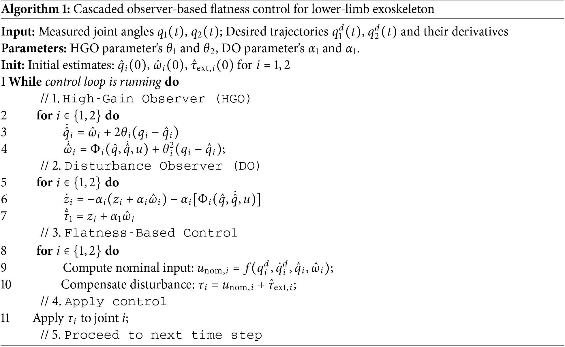
In this section, only partial state measurements,specifically, angular positions, are assumed to be available. The following pseudo-code (Algorithm 1) outlines the control architecture depicted in Fig. 2.
The simulation results obtained from the application of the control law (28) and (29), with the choice of the high gain design parameter
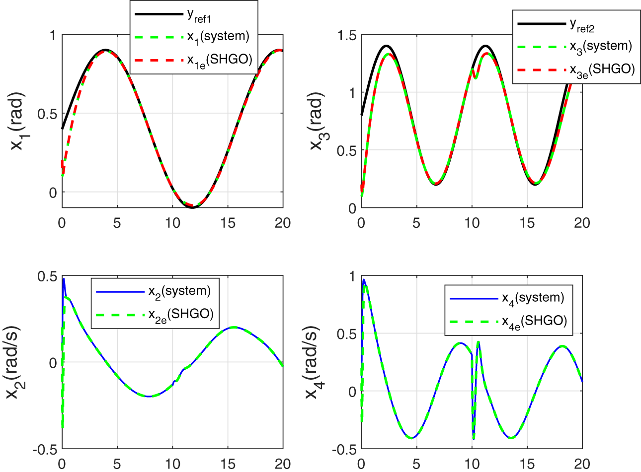
Figure 9: Tracking of joint angles
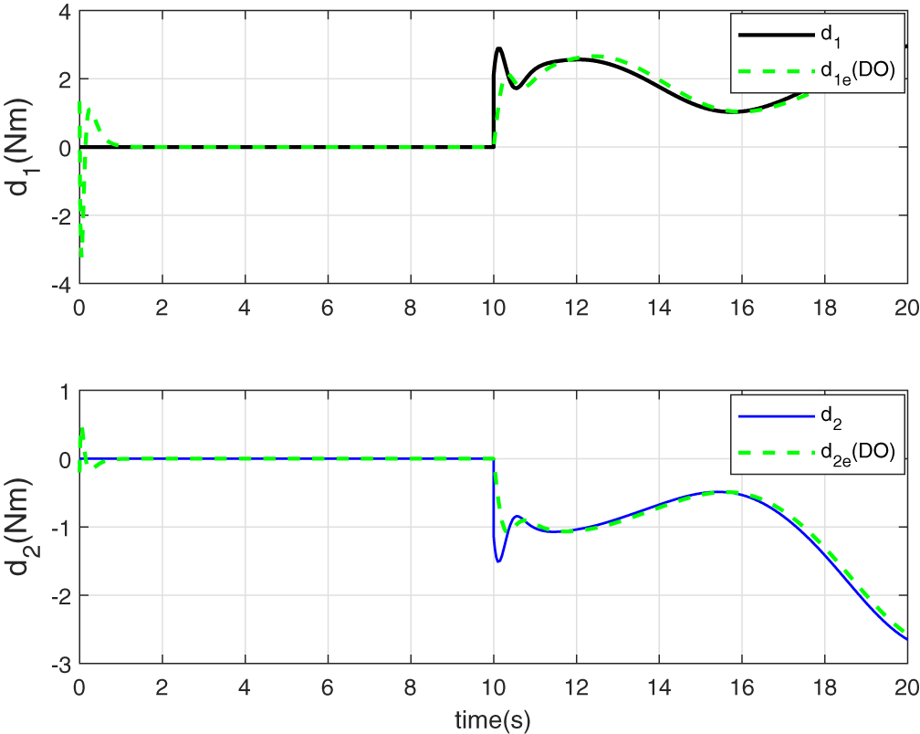
Figure 10: Estimation of unknown disturbance signals
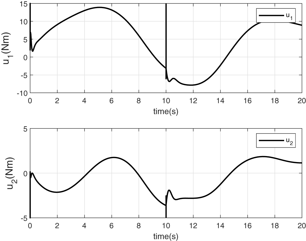
Figure 11: Applied control torques arising from cascade observers based flatness controller
As illustrated in the upper plots of Fig. 9, the system outputs accurately track the reference trajectories, demonstrating good tracking performance. The lower plots show a rapid and precise reconstruction of the unmeasured states
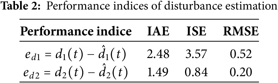
Remark 1: To evaluate the quality of disturbance estimation, the following performance indices have been selected: the Integral of Absolute Error (IAE), the Integral of Squared Error (ISE), and the Root Mean Square Error (RMSE). Each of these performance indices can be defined as follows:
We can now explicitly emphasize that:
• The significance of the tracking performance, showing that the tracking error remains very low even in the presence of abrupt disturbances and partial state measurements.
• The effectiveness of the proposed observers, as confirmed by low RMSE, IAE, and ISE values (Table 2) demonstrating accurate and rapid estimation of both state and disturbance variables.
• The superiority of the integrated control strategy, which combines estimation and compensation in real time, leading to a control law that remains smooth and bounded under challenging dynamic conditions. These improvements support the robustness, accuracy, and practical relevance of the proposed approach.
Remark 2: For all three proposed scenarios, a disturbance is introduced at time
• In the first case (nominal controller only), the system fails to preserve good tracking performance after the disturbance is introduced, as there is no mechanism to counteract its effects.
• In the second case, the disturbance is compensated using the signal estimated by the DO. This allows the controller to significantly reduce the effect of the disturbance and maintain satisfactory performance.
• In the third case, the same DO-based compensation is applied, but a HGO is added upstream to estimate unmeasured state variables (in particular, the velocities). The results remain as good as the second case in terms of performance, but the configuration is more realistic and applicable to real-world systems, where full state measurement is typically not available.
In this paper, a state feedback flatness based control strategy incorporating cascade observers was proposed for a lower-limb exoskeleton robot. A nonlinear disturbance observer was designed to estimate unknown interaction torques and compensate for model uncertainties, while a high-gain observer was employed to reconstruct unmeasured state variables. The estimated states and disturbances were integrated into the flatness-based control law, which is parameterized solely by a predictive horizon. The simulation results demonstrated the robustness and effectiveness of the proposed control approach under external perturbations and partial state measurements. The low values of performance indices confirm the high precision of the disturbance observer and its contribution to effective compensation within the controller, leading to significantly improved trajectory tracking.
Future work will focus on validating the control scheme on physiologically realistic motion trajectories, representative of actual rehabilitation exercises, to ensure clinical relevance. Moreover, the integration of wearer intention detection and motor capability adaptation will be explored to make the exoskeleton more intelligent and cooperative. Finally, in preparation for real-time implementation, it will be essential to consider the impact of sensor noise by incorporating dedicated filtering mechanisms into the observer structure.
Acknowledgement: The authors extend their appreciation to the King Salman Center for Disability Research for funding this work through Research Group No. KSRG-2024-468.
Funding Statement: This research was funded by the King Salman Center for Disability Research, through Research Group No. KSRG-2024-468.
Author Contributions: Conceptualization, Salim Hadj Said, Sahbi Boubaker, Souad Kamel and Habib Dimassi; methodology, Salim Hadj Said and Sahbi Boubaker; software, Salim Hadj Said; validation, Salim Hadj Said, Souad Kamel and Habib Dimassi; formal analysis, Salim Hadj Said, Souad Kamel and Sahbi Boubaker; investigation, Salim Hadj Said, Souad Kamel and Habib Dimassi; resources, Sahbi Boubaker; data curation, Salim Hadj Said, Souad Kamel and Habib Dimassi; writing—original draft preparation, Salim Hadj Said and Sahbi Boubaker; writing—review and editing, Sahbi Boubaker, Habib Dimassi and Souad Kamel; visualization, Salim Hadj Said; supervision, Sahbi Boubaker; project administration, Sahbi Boubaker; funding acquisition, Sahbi Boubaker. All authors reviewed the results and approved the final version of the manuscript.
Availability of Data and Materials: The datasets generated or analyzed during the current study are available from the corresponding author on reasonable request.
Ethics Approval: This study did not involve human participants or animal experiments. Therefore, ethics approval was not required.
Conflicts of Interest: The authors declare no conflicts of interest to report regarding the present study.
Abbreviations
| DO | Disturbance Observer |
| HGO | High Gain Observer |
| ESO | Extended State Observer |
| SMC | Sliding Mode Control |
| ATSMC | Adaptive Terminal Sliding Mode Control |
References
1. Abdallah C, Dawson D, Dorato P, Jamshidi M. Survey of robust control for rigid robots. IEEE Control Syst Mag. 1991;11(2):24–30. doi:10.23919/acc.1990.4790827. [Google Scholar] [CrossRef]
2. Akdoǧan E, Adli M. The design and control of a therapeutic exercise robot for lower limb rehabilitation: physiotherabot. Mechatronics. 2011;21(3):509–22. doi:10.1016/j.mechatronics.2011.01.005. [Google Scholar] [CrossRef]
3. Andrikopoulos G, Nikolakopoulos G, Manesis S. Advanced nonlinear PID-based antagonistic control for pneumatic muscle actuators. IEEE Trans Ind Electron. 2014;61(12):6926–37. doi:10.1109/tie.2014.2316255. [Google Scholar] [CrossRef]
4. Aole S, Elamvazuthi I, Waghmare L, Patre B, Meriaudeau F. Improved active disturbance rejection control for trajectory tracking control of lower limb robotic rehabilitation exoskeleton. Sensors. 2020;20:3681. doi:10.3390/s20133681. [Google Scholar] [PubMed] [CrossRef]
5. Aole S, Elamvazuthi I, Waghmare L, Patre B, Meriaudeau F. Non-linear active disturbance rejection control for upper limb rehabilitation exoskeleton. Proc Inst Mech Eng I J Syst Control Eng. 2021;235(13):606–32. doi:10.3390/s20133681. [Google Scholar] [CrossRef]
6. Aole S, Elamvazuthi I, Waghmare L, Patre B, Bhaskarwar T, Meriaudeau F, et al. Active disturbance rejection control based sinusoidal trajectory tracking for an upper limb robotic rehabilitation exoskeleton. Appl Sci. 2022;12(3):1287. doi:10.3390/s20133681. [Google Scholar] [CrossRef]
7. Baud R, Manzoori A, Ijspeert R, Bouri M. Review of control strategies for lower-limb exoskeletons to assist gait. J NeuroEng Rehabil. 2021;18(1):119. doi:10.1186/s12984-021-00906-3. [Google Scholar] [PubMed] [CrossRef]
8. Balasubramanian K, Rattan KS. Feedforward control of a non-linear pneumatic muscle system using fuzzy logic. In: The 12th IEEE International Conference on Fuzzy Systems; 2003 May 25–28; St. Louis, MO, USA. p. 272–7. doi:10.1109/fuzz.2003.1209374. [Google Scholar] [CrossRef]
9. Dorf RC, Bishop RH. Modern control systems. London, UK: Pearson; 2011. [Google Scholar]
10. Chen Z, Li Z, Chen CLP. Disturbance observer-based fuzzy control of uncertain MIMO mechanical systems with input nonlinearities and its application to robotic exoskeleton. IEEE Trans Cybern. 2017;47(4):984–94. doi:10.1109/tcyb.2016.2536149. [Google Scholar] [PubMed] [CrossRef]
11. Chen CF, Du ZJ, He L, Long H, Jia QW, Dong MW, et al. Active disturbance rejection with fast terminal sliding mode control for a lower limb exoskeleton in swing phase. IEEE Access. 2019;7:72343–57. doi:10.1109/access.2019.2918721. [Google Scholar] [CrossRef]
12. Choi TY, Lee JJ. Control of manipulator using pneumatic muscles for enhanced safety. IEEE Trans Ind Electron. 2010;57(8):2815–25. doi:10.1109/tie.2009.2036632. [Google Scholar] [CrossRef]
13. Estrada A, Plestan F. Second order sliding mode output feedback control with switching gains—application to the control of a pneumatic actuator. J Frankl Inst. 2014;351(4):2335–55. doi:10.1016/j.jfranklin.2013.07.011. [Google Scholar] [CrossRef]
14. Frisoli A, Procopio C, Chisari C, Creatini I, Bonfiglio L, Bergamasco M, et al. Positive effects of robotic exoskeleton training of upper limb reaching movements after stroke. J Neuroeng Rehabil. 2012;9(1):36 doi:10.1109/biorob.2012.6290843. [Google Scholar] [CrossRef]
15. Dulf EH, Both R, Muresan CI. Active disturbance rejection controller for a separation column. In: 2014 IEEE International Conference on Automation, Quality and Testing, Robotics; 2014 May 22–24; Cluj-Napoca, Romania. p. 1–6. doi:10.1109/aqtr.2014.6857906. [Google Scholar] [CrossRef]
16. Delp SL, Anderson FC, Arnold AS, Loan P, Habib A, John CT, et al. OpenSim: open-source software to create and analyze dynamic simulations of movement. IEEE Trans Biomed Eng. 2007;54:1940–50. doi:10.1109/tbme.2007.901024. [Google Scholar] [PubMed] [CrossRef]
17. Ghorbel F, Srinivasan B, Spong MW. On the uniform boundedness of the inertia matrix of serial robot manipulators. J Robot Syst. 1998;15(1):17–28. doi:10.1002/(sici)1097-4563(199812)15:1<17::aid-rob2>3.0.co;2-v. [Google Scholar] [CrossRef]
18. Guo Z, Yu H, Yin YH. Developing a mobile lower limb robotic exoskeleton for gait rehabilitation. J Med Devices. 2014;8:044503. doi:10.1115/1.4026900. [Google Scholar] [CrossRef]
19. Han SI, Lee JM. Output-tracking-error-constrained robust positioning control for a nonsmooth nonlinear dynamic system. IEEE Trans Ind Electron. 2014;61:6882–91. doi:10.1109/tie.2014.2316263. [Google Scholar] [CrossRef]
20. Huang CE, Li D, Xue Y. Active disturbance rejection control for the ALSTOM gasifier benchmark problem. Control Eng Pract. 2013;21:556–64 doi:10.1016/j.conengprac.2012.11.014. [Google Scholar] [CrossRef]
21. Hussain S, Xie SQ, Jamwal PK. Adaptive impedance control of a robotic orthosis for gait rehabilitation. IEEE Trans Cybern. 2013;43(3):1025–34. doi:10.1109/tsmcb.2012.2222374. [Google Scholar] [PubMed] [CrossRef]
22. Al-Awad NA, Humaidi AJ, Alaraji AS. Observer sliding mode control design for lower exoskeleton system: rehabilitation case. J Robot Control. 2022;3(4):476–84. doi:10.18196/jrc.v3i4.15239. [Google Scholar] [CrossRef]
23. Al-Awad NA, Humaidi AJ, Al-Araji AS. Fractional multi-loop active disturbance rejection control for a lower knee exoskeleton system. Acta Polytech. 2023;63(3):158–70. doi:10.14311/ap.2023.63.0158. [Google Scholar] [CrossRef]
24. Al-Awad NA, Humaidi AJ, Alaraji AS. A novel approach of multi-loop control based-ADRC for improving lower knee position exoskeleton system. Int Rev Appl Sci Eng. 2023;14(3):316–24. doi:10.1556/1848.2023.00546. [Google Scholar] [CrossRef]
25. Al-Awad NA, Humaidi AJ, Alaraji AS. Sliding mode-based active disturbance rejection control of assistive exoskeleton device for rehabilitation of disabled lower limbs. An Acad Bras Ciênc. 2023;95(2):e20220680. doi:10.1590/0001-3765202320220680. [Google Scholar] [PubMed] [CrossRef]
26. Jakob I, Kollreider A, Germanotta M, Benetti F, Cruciani A, Padua L, et al. Robotic and sensor technology for upper limb rehabilitation. PM&R. 2018;10:S189–97. doi:10.1016/j.pmrj.2018.07.011. [Google Scholar] [PubMed] [CrossRef]
27. Dali Hassen M, Laamiri I, Bouguila N. A robust adaptive non-singular terminal sliding mode control: application to an upper-limb exoskeleton with disturbances and uncertain dynamics. Inf Technol Control. 2024;53(1):171–86. doi:10.5755/j01.itc.53.1.33752. [Google Scholar] [CrossRef]
28. Lee BK, Lee HD, Lee JY, Shin K, Han JS, Han CS. Development of dynamic model-based controller for upper limb exoskeleton robot. In: 2012 IEEE International Conference on Robotics and Automation; 2012 May 14–18; Saint Paul, MN, USA. p. 3173–8. doi:10.1109/icra.2012.6224675. [Google Scholar] [CrossRef]
29. Wang Y, Wang H, Tian Y. Nonlinear disturbance observer based flexible-boundary prescribed performance control for a lower limb exoskeleton. Int J Syst Sci. 2021;52(5):1001–17. doi:10.1080/00207721.2021.1922952. [Google Scholar] [CrossRef]
30. Rigatos G, Abbaszadeh M, Pomares J. Flatness-based disturbance observer for exoskeleton robots under time-delayed contact forces. Adv Control Appl. 2022;4(2):e100. doi:10.1002/adc2.100. [Google Scholar] [CrossRef]
31. Bouraoui I, Farza M, Ménard T, Ben Abdennour R, M’Saad M, Mosrati H. Observer design for a class of uncertain nonlinear systems with sampled outputs—application to the estimation of kinetic rates in bioreactors. Automatica. 2015;55(3):78–87. doi:10.1016/j.automatica.2015.02.036. [Google Scholar] [CrossRef]
32. Miladi N, Dimassi H, Hadj Said S, M’Sahli F. Explicit nonlinear model predictive control tracking control based on a sliding mode observer for a quadrotor subject to disturbances. Trans Inst Meas Control. 2019;42(2):214–27. doi:10.1177/0142331219865816. [Google Scholar] [CrossRef]
Cite This Article
 Copyright © 2025 The Author(s). Published by Tech Science Press.
This work is licensed under a Creative Commons Attribution 4.0 International License , which permits unrestricted use, distribution, and reproduction in any medium, provided the original work is properly cited.
 Downloads
 Citation Tools