
 Submit a Paper
 Propose a Special lssue
 Open Access
ARTICLE

Enhanced Capacity Reversible Data Hiding Based on Pixel Value Ordering in Triple Stego Images
Faculty of Information Technology, University of Transport and Communications, Hanoi, 100000, Vietnam
* Corresponding Author: Ngoc Dung Bui. Email:
(This article belongs to the Special Issue: New Trends in Image Processing)
Computers, Materials & Continua 2026, 86(1), 1-16. https://doi.org/10.32604/cmc.2025.069355
Received 21 June 2025; Accepted 01 October 2025; Issue published 10 November 2025
 View Full Text
 Download PDF
Abstract
Reversible data hiding (RDH) enables secret data embedding while preserving complete cover image recovery, making it crucial for applications requiring image integrity. The pixel value ordering (PVO) technique used in multi-stego images provides good image quality but often results in low embedding capability. To address these challenges, this paper proposes a high-capacity RDH scheme based on PVO that generates three stego images from a single cover image. The cover image is partitioned into non-overlapping blocks with pixels sorted in ascending order. Four secret bits are embedded into each block’s maximum pixel value, while three additional bits are embedded into the second-largest value when the pixel difference exceeds a predefined threshold. A similar embedding strategy is also applied to the minimum side of the block, including the second-smallest pixel value. This design enables each block to embed up to 14 bits of secret data. Experimental results demonstrate that the proposed method achieves significantly higher embedding capacity and improved visual quality compared to existing triple-stego RDH approaches, advancing the field of reversible steganography.Keywords
Data hiding is a field of information security. Data hiding is a technique of embedding secret information into a digital product to protect the information or the integrity of the product. Reversible data hiding is a major form of Data hiding. Besides extracting the message, it also restores the cover image. There are many approaches used in RDH, such as difference expansion (DE), histogram shifting (HS), difference error expansion, pixel values ordering, embedding on encrypted images, etc.
This paper presents an RDH method based on the PVO technique. The first RDH-based PVO is proposed by Li et al. [1]. After that, this approach has attracted considerable attention from researchers [2–8]. According to [1], the original image is first divided into discrete blocks. Within each block, the pixel values are sorted in ascending order. Subsequently, the algorithm calculates two types of errors: the difference between the largest and the second-largest pixel values (the maximum error) and the difference between the smallest and the second-smallest pixel values (the minimum error). If the maximum error equals 1, it will embed a bit (a similar process is performed at the smallest side when the smallest error is equal to −1). So, the order of a pixel sequence remains unchanged to serve the information recovery process. Scheme [2] improves [1] by using blocks with the maximum error equal to zero to improve embedding capacity. Ou et al. [3] proposed PVO-k, an improved version of the original PVO method. In this approach, a bit is embedded into k largest pixels if the error between the largest and the second-largest pixel values is zero. Zhang et al. [7] exploit bit-plane segmentation and PVO to embed in rough image regions. Wahed and Nyeem [8] employ a recursive embedding scheme that alternates between horizontal and vertical pixel correlations, enabling dynamic adaptation to different capacity demands.
The technique of reversible data hiding using dual images has recently gained increased attention and development due to its remarkable advantage in embedding capacity [5,9–13]. The dual-image technique was first introduced by Chang et al. [9], based on the Exploiting Modification Direction (EMD) method. In their approach, a
Subsequently, Niu and Shen [5] proposed an embedding method based on the prediction errors between the second-largest and the largest pixel values, as well as between the second-smallest and the smallest. For each of these error values, they designed embedding rules that allow 1 to 3 bits to be embedded per largest (or smallest) pixel, resulting in two stego images carrying the hidden information. Sao et al. [12] improved image quality by selecting the most frequently occurring 5-bit secret element to embed into pixel pairs with a difference of zero. The hidden data is first divided into 5-bit elements, which are then sorted in descending order of frequency. Higher-frequency elements are associated with lower variation in pixel values, thsereby significantly enhancing the quality of the stego images while also improving embedding capacity. Nguyen and Dao [13] also proposed a dual-image PVO-based method. The authors utilized two variables, the indices of the secret bits and a location map. Based on these two variables, they embedded one bit into each pair of pixels. The method proposed by Weng et al. [15] exemplifies the application of PVO in this context, highlighting that PVO continues to attract significant research interest, even in emerging application domains.
RDH using three stego images offers several advantages. The most notable is its large embedding capacity. With three shadow images, the embedding capacity can reach up to one million bits while maintaining high stego image quality. Another advantage lies in its applicability to multi-party scenarios. For instance, if a message is intended to be disclosed only when all three recipients are present, the message can be embedded using RDH based on three stego images. Each individual receives one stego image, and the secret message can only be extracted when all three images are combined. This property makes the method particularly suitable for applications requiring objectivity and mutual consent. RDH based on three stego images is an emerging research direction, with notable contributions such as [16,17]. In [16], the authors divide the algorithm into three phases. In the first phase, each 3-bit element of the secret message is embedded into individual pixels of the cover image, resulting in three initial stego images. In the second phase, additional secret bits are embedded into these initial stego images using a prediction error-based PVO technique, producing three intermediate stego images. Finally, in the third phase, more secret bits are embedded by modifying prediction errors in the intermediate stego images to obtain the final stego images. Although this method achieves a high embedding capacity, it suffers from relatively low stego image quality and high computational complexity. Chen and Chang [17] also proposed a three-phase embedding scheme. In the first phase, the secret bits are converted into base-5 numbers and embedded into pairs of pixels. In the second phase, additional secret bits are transformed into base-6 numbers and embedded into the stego pixels generated from the first phase. In the final phase, more base-5 secret numbers are embedded into the stego pixels obtained from the previous phase. This method achieves both high embedding capacity and good stego image quality.
Building upon the advantages of reversible data hiding based on three stego images, this paper proposes a novel RDH scheme that also utilizes three stego images. The proposed method is based on the PVO technique, where the cover image is divided into blocks. For each block, 4 to 7 secret bits are embedded into the largest pixel (as well as the smallest pixel), with a maximum modification of 2 units. Additionally, the second-largest and second-smallest pixels may be altered by at most 1 unit. In total, each block is capable of embedding 8 to 14 bits. Experimental results and analysis demonstrate that the proposed method achieves high embedding capacity while maintaining low computational complexity.
The remainder of this paper is organized as follows: Section 2 presents the related works. Section 3 describes the proposed method in detail. Section 4 provides experimental results and analysis. Finally, the conclusion is given in the Section 5.
Li et al. [1] is regarded as the first work to introduce the PVO method. In this approach, the original image is divided into non-overlapping blocks. The pixel values within each block are sorted in ascending order. For a block containing n pixels
Then, a secret data
Finally, the sequence of stego pixels
An important characteristic of PVO-based methods is that the order of pixel values remains unchanged after embedding. This characteristic ensures the correctness of both data extraction and original image recovery. Since then, many methods have adopted this idea, opening a new research direction in the field of data hiding. The method proposed by Li et al. [1] achieves high stego image quality because each pixel used for embedding is modified by at most 1 unit; however, its embedding capacity remains limited, as each block can carry at most 2 bits.
This method, proposed by Niu and Shen [5], is based on the PVO method for stego dual images, hereinafter referred to as the NS method. Same as the PVO method, NS method also divides the original image into blocks, and after that, with each block, sorts pixel values in the block in ascending order

As shown in Table 1, each block can embed up to 3 bits on each side, with a maximum pixel modification of 2 units. However, this maximum embedding case occurs with a probability of only 0.5. On average, the expected number of embedded bits per side is
The method proposed by Sao et al. [6], which is an improvement of the NS method, will hereinafter be referred to as the SLL method. In this approach, the original image is divided into blocks, and the pixel values within each block are sorted in ascending order. Four secret bits are embedded into the maximum pixel, and another four bits are embedded into the minimum pixel. The recovery of the original block and the extraction of the embedded secret bits are then performed based on the correlation among the three stego maximum pixels (and similarly, the three stego minimum pixels).
This method fully utilizes all possible
In the NS method, pixel values are modified by at most one unit, which helps maintain high image quality. However, each image block can embed at most 6 bits, with an average of 4 bits, resulting in an embedding ratio of only 2 bits per block, a relatively low rate. In contrast, SLL method embeds data into the largest and smallest pixels of each block, achieving up to 8 bits per block with an embedding ratio of approximately 2.7 bits per block. Both methods employ the PVO technique but utilize only the largest and smallest value pixels, leaving the second-largest and second-smallest value pixels unused.
The proposed method improves upon both NS and SLL methods by additionally exploiting the second-largest and second-smallest pixels in each block. As a result, it can embed up to 14 bits per block, with an average embedding ratio of 4.7 bits per block, at least equal to that of the SLL method. To ensure accurate data extraction and image reconstruction, two thresholds is employed, along with an optimal threshold selection strategy to further enhance embedding capacity.
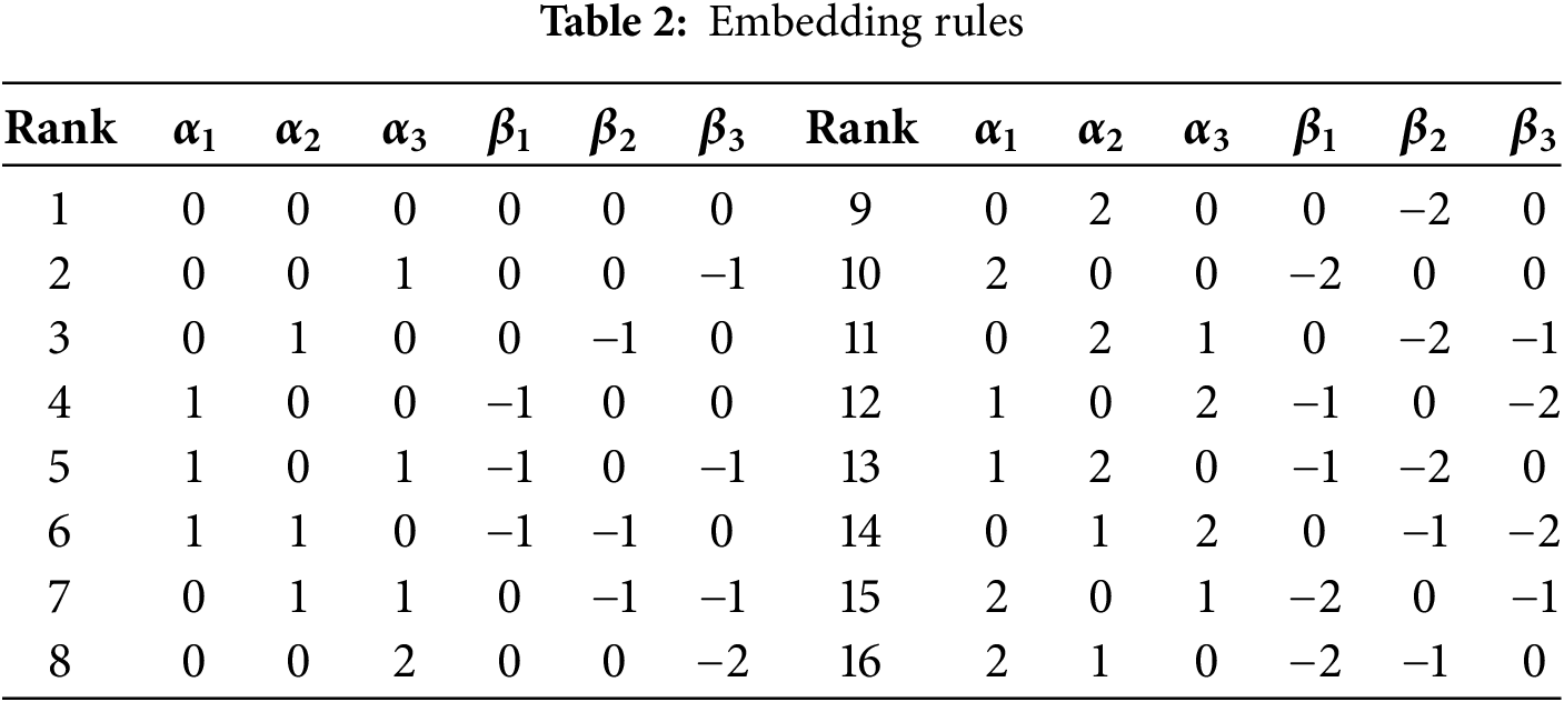
Since pixel values can be altered by up to 2 units during embedding, this may potentially degrade image quality. The proposed method incorporates a transformation selection mechanism inspired by the technique in [12]. Specifically, it uses a rank table to determine embedding parameters, allowing frequently occurring 4-bit groups to be embedded with minimal pixel modification.
Moreover, the proposed method adopts a two-phase embedding process as shown in the Fig. 1. In the first phase, data is embedded into the largest and smallest pixels of each block. In the second phase, additional data is embedded into the second-largest and second-smallest pixels, thereby maximizing the embedding potential of each block.
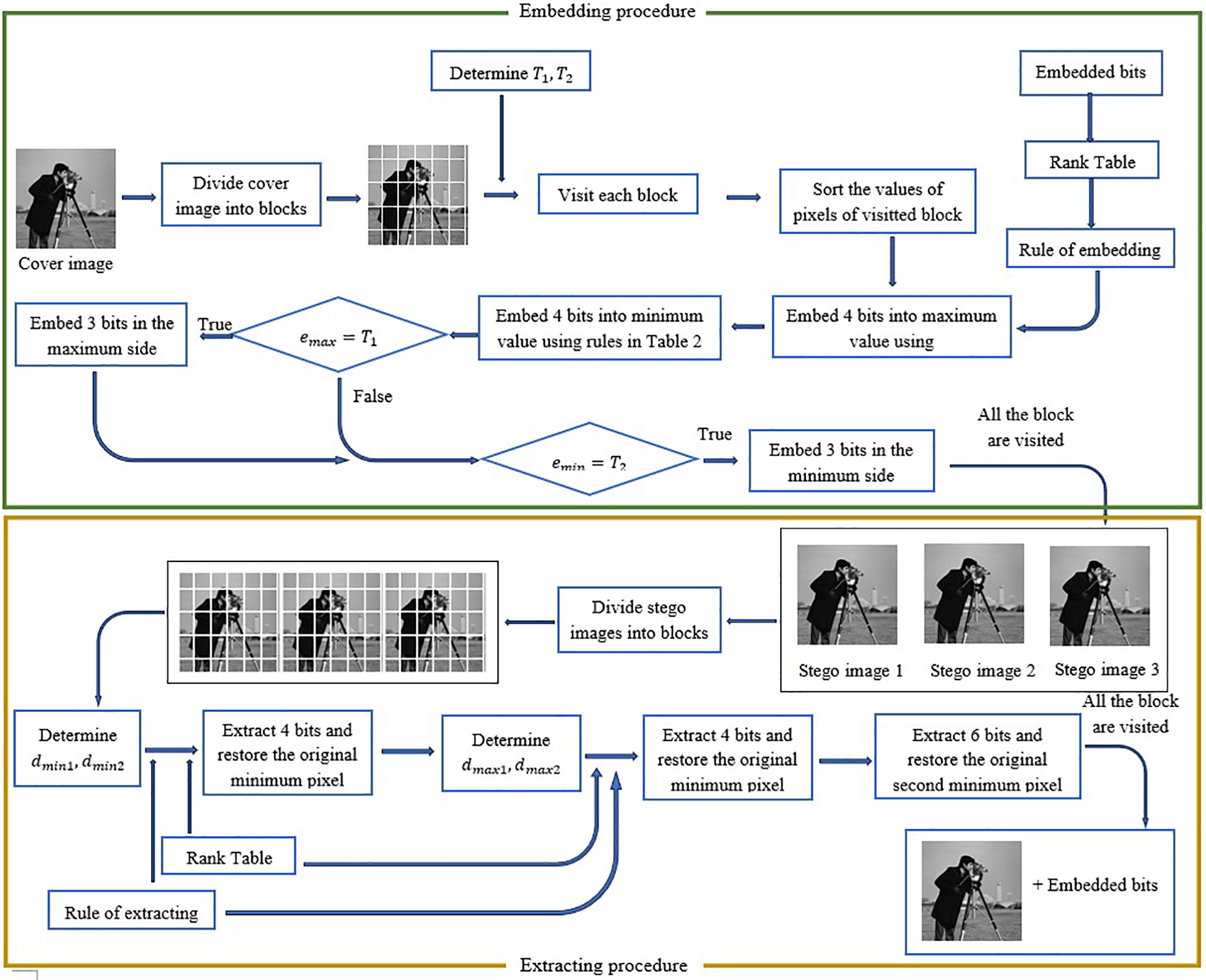
Figure 1: Schema of embedding and extracting procedures
The secret message is divided into a sequence X of 4-bit elements, and a histogram of X is constructed. The 4-bit element with the highest frequency is assigned rank 1, continuing similarly until all 16 possible 4-bit groups are ranked. Let
Table 2 shows the correspondence between each rank and the parameters
In the extraction procedure, the rank of the 4-bit element embedded into the cover image is determined based on the Extracting Rule Table. Table 3 defines the rank of 4-bit elements and the corresponding


3.2 Embedding Algorithm in a Block
3.2.1 Embedding Algorithm in a Block in First Phase
This section presents the algorithm for embedding a bit array B (8 bits) into a block
The embedding algorithm for a block is outlined below:
Embedding in the maximum side
Step 1: Sort the pixel values in the block
Step 2: Embedding the array of secret bits
Take 4 bits from the array B then refer to Section 3.1 to obtain
After embedding on the maximum side, we proceed to embed on the minimum side as follows:
Embedding in the minimum side
Embed the array of secret bits.
Let
3.2.2 Embedding Algorithm in a Block in Second Phase
This section presents the algorithm for embedding 6 bits from B into the second maximum and second minimum pixel, derived from the original block and three embedding parameters obtained during the first phase. Two thresholds,
The detailed embedding algorithm for a single block is outlined below:
Embedding in the maximum side
Using the three parameters
Step 2: If any of the values
Otherwise (
where
Embedding in the minimum side
Similar to the maximum side, using
3.3 Extracting Algorithm in a Block
3.3.1 Extracting Algorithm in a Block in First Phase
Given three stego blocks
Step 1: Sorting Sort the pixel values in each of the three stego blocks
Step 2: Extracting secret bits and restoring the original pixel on the minimum side
Calculate the differences among the three stego blocks as follows:
Step 3: Based on the values of
Step 4: Extract the secret bits and restore the original pixel on the maximum side:
Compute the differences among the three stego blocks as follows:
Step 5: Extract the secret bits and restore the original maximum pixel.
Based on the values of
3.3.2 Extracting Algorithm in a Block in Second Phase
The extraction process uses thresholds
Step 1: Extract the secret bits and restore the original second minimum pixel.
First, estimate the supposed original second minimum pixel and compute the corresponding three prediction errors for the three stego blocks, as outlined below:
If any of the three values
Otherwise, no bit is extracted, and the second minimum pixel is restored as
Step 2: Extracting the secret bits and restoring the original second maximum pixel:
First, compute the expected second maximum pixel and calculate the three corresponding errors from the three stego blocks as follows:
If any of the three values
Otherwise, no bits are extracted, and the second maximum pixel is restored as
The remaining pixels in the block are identical to those in the original block.
3.4 Procedure of Embedding in an Image
To determine the optimal thresholds
First, we calculate all the prediction errors
Here,
Given an original image I and an array of secret bits B, the goal is to embed B into I to produce three stego images.
Step 1: Divide the original image into non-overlapping blocks of size
Step 2: Determine or calculate the thresholds
Step 3: Determine the extra information: To support the extraction process, additional information must be embedded:
32 bits to store the thresholds
Take the last 32 least significant bits (LSBs) from the first stego image, the last 64 LSBs from the second stego image, and the last 32 LSBs from the third stego image. Prepend these 128 bits to the beginning of the secret bitstream B to obtain the extended bitstream B′.
Step 4: Embed the secret bit array B′ into the image blocks using the algorithm described in Section 3.2.1. Mark the last block that is used for embedding during the first phase.
Step 5: Continue embedding the remaining bits of B′ into the blocks using the algorithm in Section 3.2.2. Mark the last block used in the second phase.
Step 6: Embed the thresholds
Given the three stego images
Step 1: Extract Extra Information:
Extract the last 32 LSBs from
Step 2: Divide the stego images into blocks of size
Step 3: The extraction and restoration process follows a two-phase order: first, the secret bits are extracted and the original image is restored from all blocks using the algorithm defined for the first extraction phase; then, the process continues with the remaining blocks according to the second phase extraction algorithm.
Begin by traversing each block in the three stego images to extract the first 128 bits and restore the original block using the algorithm described in Section 3.3. After extraction, reinsert these 128 bits into the last 32 LSBs of the first stego image, the last 64 LSBs of the second stego image, and the last 32 LSBs of the third stego image using the LSB embedding method.
Step 4: Continue scanning each block in the three stego images to extract the remaining bits of the secret message B and restore the original image using the algorithm described in Section 3.3.
Finally, the complete secret bitstream B is recovered, and the original image is successfully reconstructed.
To analyze the computational complexity of the proposed algorithm, we examine each processing step: The image is divided into non-overlapping blocks of size
We perform experiments on 15 standard grayscale images of size
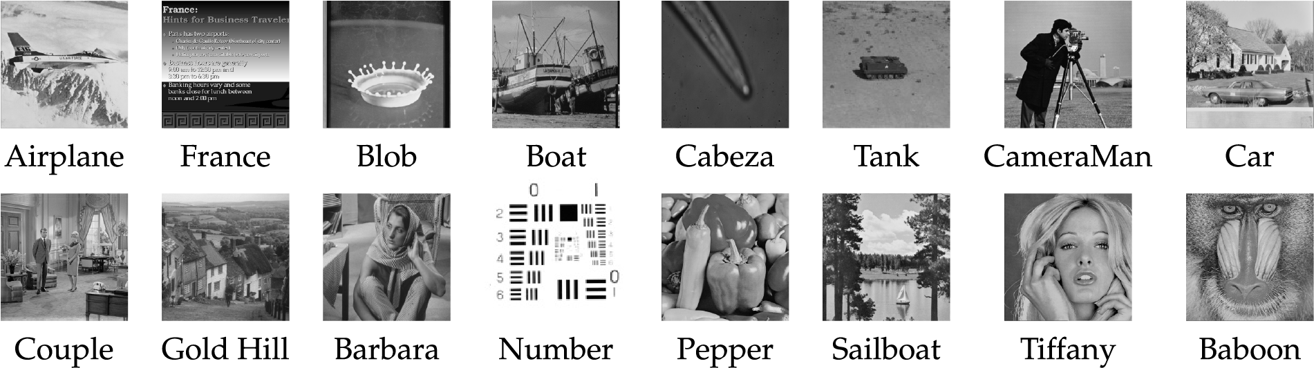
Figure 2: Experimental images and the data image are embedded in the experimental images
We employ two key metrics to evaluate the efficiency of each method: embedding capacity, measured by the total number of embedded bits and the bits per pixel (bpp), and peak signal-to-noise ratio (PSNR), measured in decibels (dB). The PSNR metric assesses image quality by quantifying the distortion between the cover image and the stego images. A higher PSNR indicates better image quality. The embedding capacity can be calculated using the following ratio:
When the image is divided into blocks of size
In the proposed method, data embedding is carried out in two phases. In the first phase, each image block can embed 4 bits into the maximum pixel and 4 bits into the minimum pixel. In the second phase, if specific conditions are satisfied, an additional 6 bits may be embedded (3 bits into the second-largest pixel and 3 bits into the second-smallest pixel).
Therefore, the theoretical embedding capacity (EC) and embedding rate (ER) for an original image of size
The number of non-overlapping blocks is
The embedding capacity in the first phase is
The number of cases in the second phase that satisfy the embedding condition is defined as
Thus, the total embedding capacity is:
Table 5 compares the embedding capacity, in terms of the total number of bits and bits per pixel (bpp), for different methods. The comparison is conducted by dividing the cover image into blocks of size
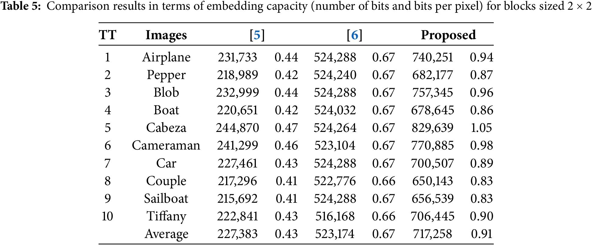
In [5], capacity is estimated based on probability and may slightly exceed the actual capacity when using a random bit array. Each block in [5] can embed from 1 up to 3 bits across two stego images. In contrast, [6] consistently embeds up to 8 bits per block across three stego images. Our proposed method improves on this by embedding from 8 to 14 bits per block, providing a higher overall capacity.
Table 6 presents a comparison of embedding capacities when the cover image is divided into blocks of size

On average, the embedding capacity of [5] is 1.12 bits per pixel (bpp), the Ref. [17] achieves 1.23 bpp, while both the Ref. [6] and the proposed methods reach 1.33 bpp. Notably, although the capacity of the proposed method is on par with [6], the proposed method offers superior stego image quality. Moreover, the proposed method outperforms [17] by a significant margin an increase of 78,116 bits, highlighting the effectiveness of the proposed embedding strategy.
We conducted a comparison using the UCID database, which contains 1338 images. Fig. 3 illustrates the embedding capacity of three methods [5,6], and the proposed method—when the original images are divided into blocks of size
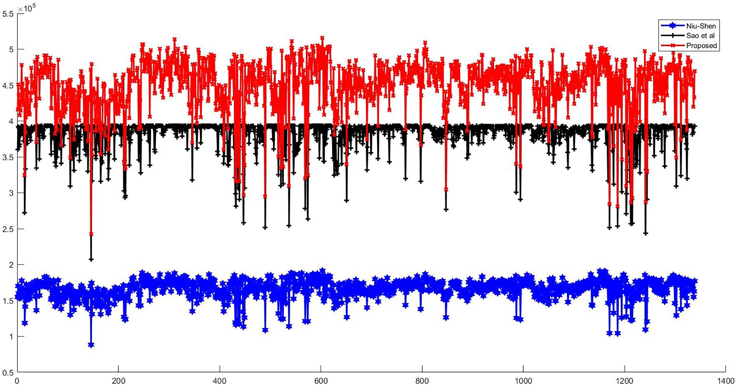
Figure 3: Comparison of embedding capacity with dividing the cover image into a block

Figure 4: Comparison of embedding capacity with dividing the cover image into blocks
In terms of PSNR comparison, we evaluate the performance using 15 data images of varying sizes, includes Barbara sized
Fig. 5 presents a chart displaying the average PSNR values across the 8 experimental images when embedding the 15 data images. This chart illustrates that the proposed method consistently achieves the highest average PSNR, indicating superior stego image quality. In this figure, we also observe that when the embedded data is the image Number (sized

Figure 5: Comparisons of the proposed method with existing works in PSNR under different payloads [5,6,17]

In this paper, we propose a novel reversible data hiding method based on PVO that generates three stego images. The proposed approach is capable of embedding up to 14 bits per block by utilizing both the maximum and second maximum, as well as the minimum and second minimum pixel values within each block. To enhance the quality of the stego images, the method incorporates bit correlation analysis and image transformation techniques. Experimental results on standard test images and a dataset of 1338 images from the UCID database demonstrate that the proposed method achieves high embedding capacity while maintaining excellent visual quality in the stego images.
Acknowledgement: The authors extend their appreciation to the University of Transport and Communications (UTC).
Funding Statement: This research is funded by University of Transport and Communications (UTC) under grant number T2025-CN-004.
Author Contributions: The authors confirm contribution to the paper as follows: study conception and design: Kim Sao Nguyen; analysis and interpretation of results: Kim Sao Nguyen, Ngoc Dung Bui; draft manuscript preparation: Kim Sao Nguyen, Ngoc Dung Bui. All authors reviewed the results and approved the final version of the manuscript.
Availability of Data and Materials: Not applicable.
Ethics Approval: Not applicable.
Conflicts of Interest: The authors declare no conflicts of interest to report regarding the present study.
References
1. Li X, Li J, Li B, Yang B. High-fidelity reversible data hiding scheme based on pixel-value-ordering and prediction-error expansion. Signal Process. 2013;93(1):198–205. doi:10.1016/j.sigpro.2012.07.025. [Google Scholar] [CrossRef]
2. Peng F, Li X, Yang B. Improved PVO-based reversible data hiding. Digit Signal Process. 2014;25(2):255–65. doi:10.1016/j.dsp.2013.11.002. [Google Scholar] [CrossRef]
3. Ou B, Li X, Zhao Y, Ni R. Reversible data hiding using invariant pixel-value-ordering and prediction-error expansion. Signal Process Image Commun. 2014;29(7):760–72. doi:10.1016/j.image.2014.05.003. [Google Scholar] [CrossRef]
4. Pan Z, Gao E. Reversible data hiding based on novel embedding structure PVO and adaptive block-merging strategy. Multimed Tools Appl. 2019;78(18):26047–71. doi:10.1007/s11042-019-7692-3. [Google Scholar] [CrossRef]
5. Niu Y, Shen S. A novel pixel value ordering reversible data hiding based on dual-image. Multimed Tools Appl. 2022;81(10):13751–71. doi:10.1007/s11042-022-12149-y. [Google Scholar] [CrossRef]
6. Sao NK, Luyen CT, Linh MV. An efficient pixel value ordering data hiding method based on three stego images. TNU J Sci Technol. 2022;227(16):233–40. doi: 10.34238/tnu-jst.6869. [Google Scholar] [CrossRef]
7. Zhang Z, Wang W, Zhao Z, Wang E. PVO-based reversible data hiding using bit plane segmentation and pixel expansion. J Inf Secur Appl. 2023;79:103649 doi: 10.1016/j.jisa.2023.103649. [Google Scholar] [CrossRef]
8. Wahed MA, Nyeem H. High-capacity reversible data hiding with iterative dual pixel value ordering. Alexandria Eng J. 2025;121:580–91 doi: 10.1016/j.aej.2025.02.088. [Google Scholar] [CrossRef]
9. Chang CC, Kieu TD, Chou YC. Reversible data hiding scheme using two steganographic images. In: TENCON 2007-2007 IEEE Region 10 Conference; 2007 Oct 30–Nov 2; Taipei, Taiwan. p. 1–4. doi:10.1109/tencon.2007.4483783. [Google Scholar] [CrossRef]
10. Chang CC, Lu TC, Horng G, Huang YH, Hsu YM. A high payload data embedding scheme using dual stego-images with reversibility. In: 2013 9th International Conference on Information, Communications & Signal Processing; 2013 Dec 10–13; Tainan, Taiwan. p. 1–5. [Google Scholar]
11. Lu TC, Chi LP, Wu CH, Chang HP. Reversible data hiding in dual stego-images using frequency-based encoding strategy. Multimed Tools Appl. 2017;76:23903–29. doi:10.1007/s11042-016-4135-2. [Google Scholar] [CrossRef]
12. Sao NK, Thanh TX, Hong MT. Reversible data hiding based on dual images adapts to the secret message. J Inf Hiding Multim Signal Process. 2023;14(1):20–30. [Google Scholar]
13. Nguyen TD, Dao TT. A novel PVO-based RDH scheme utilizes an interleaved data embedding technique using dual-pixels. J Inf Secur Appl. 2025;89(1):103939. doi:10.1016/j.jisa.2024.103939. [Google Scholar] [CrossRef]
14. Lu TC, Wu JH, Huang CC. Dual-image-based reversible data hiding method using center folding strategy. Signal Process. 2015;115(4):195–213. doi:10.1016/j.sigpro.2015.03.017. [Google Scholar] [CrossRef]
15. Weng CY, Lin TW, Weng HY, Huang CT. Enhanced reversible data hiding in encrypted images via median preserving pixel value ordering and block-wise difference preservation. Signal Image Video Process. 2025;19(6):1–13. doi:10.1007/s11760-025-04054-2. [Google Scholar] [CrossRef]
16. Xie XZ, Chang CC, Lin CC. A hybrid reversible data hiding for multiple images with high embedding capacity. IEEE Access. 2019;8:37–52. doi:10.1109/access.2019.2961764. [Google Scholar] [CrossRef]
17. Chen S, Chang CC. Reversible data hiding based on three shadow images using rhombus magic matrix. J Vis Commun Image Represent. 2021;76(3):103064. doi:10.1016/j.jvcir.2021.103064. [Google Scholar] [CrossRef]
Cite This Article
 Copyright © 2026 The Author(s). Published by Tech Science Press.
This work is licensed under a Creative Commons Attribution 4.0 International License , which permits unrestricted use, distribution, and reproduction in any medium, provided the original work is properly cited.
 Downloads
 Citation Tools