
 Submit a Paper
 Propose a Special lssue
 Open Access
ARTICLE

Energy Efficiency and Total Mission Completion Time Tradeoff in Multiple UAVs-Mounted IRS-Assisted Data Collection System
School of Information and Communication, Guilin University of Electronic Technology, Guilin, 541004, China
* Corresponding Author: Hongbin Chen. Email:
(This article belongs to the Special Issue: Advancements in Mobile Computing for the Internet of Things: Architectures, Applications, and Challenges)
Computers, Materials & Continua 2026, 86(2), 1-25. https://doi.org/10.32604/cmc.2025.072776
Received 03 September 2025; Accepted 15 October 2025; Issue published 09 December 2025
 View Full Text
 Download PDF
Abstract
UAV-mounted intelligent reflecting surface (IRS) helps address the line-of-sight (LoS) blockage between sensor nodes (SNs) and the fusion center (FC) in Internet of Things (IoT). This paper considers an IoT assisted by multiple UAVs-mounted IRS (U-IRS), where the data from ground SNs are transmitted to the FC. In practice, energy efficiency (EE) and mission completion time are crucial metrics for evaluating system performance and operational costs. Recognizing their importance during data collection, we formulate a multi-objective optimization problem to maximize EE and minimize total mission completion time simultaneously. To characterize this tradeoff while considering optimization objective consistency, we construct an optimization problem that minimizes the weighted sum of the total mission completion time and the reciprocal of EE. Due to the non-convex nature of the formulated problem, obtaining optimal solutions is generally challenging. To tackle this issue, we decompose it into three sub-problems: UAV-SN association, number of reflecting elements allocation, and UAV trajectory optimization. An iterative algorithm combining genetic algorithm, CS-BJ algorithm, and successive convex approximation technique is proposed to solve these sub-problems. Simulation results demonstrate that when the transmitted data amount is 10 and 30 Mbits, compared to the static collection benchmark (the UAV hovers directly above each SN), the EE of the proposed method improves by more than 10.4% and 5.2%, while the total mission completion time is reduced by more than 5.4% and 3.3%, respectively.Keywords
Sensors can be deployed in farmlands to collect environmental data such as soil moisture, air temperature, and wind speed, laying the foundation for Internet of Things (IoT) in precision agriculture [1]. However, limited energy storage restricts their operational lifespan. If sensor-collected data cannot be transmitted to the fusion center (FC) promptly, the finite memory capacity of sensors may lead to data overwriting. Furthermore, obstacles between sensors and the FC can result in incomplete data transmission due to the lack of a direct line-of-sight (LoS) path.
To address these issues, unmanned aerial vehicles (UAVs) have been leveraged as mobile base stations (BSs), relays, or data collectors [2]. Their high mobility and flexible deployment enable them to establish effective communication links, effectively mitigating non-line-of-sight (NLoS) problems. Nevertheless, UAVs are constrained by battery power, limiting their flight range and operational duration. This makes optimizing UAV trajectories crucial for energy-efficient data collection, especially when sensor nodes (SNs) are widely dispersed [3]. For tasks beyond the capability of a single UAV, collaborative multi-UAV systems are deployed [4], often by partitioning SNs among UAVs for full coverage [5]. Research in multi-UAV systems has focused on various objectives, including minimizing energy consumption [6], reducing the maximum task completion time [7], lowering costs [8], and enhancing data collection rates [9]. Further studies explore tradeoffs between performance metrics, such as balancing computation capacity and energy consumption [10] or optimizing energy usage vs. task completion time [11].
As another way to improve channel quality, intelligent reflecting surface (IRS) manipulates incident signal propagation [12], enabling communication between SNs and FC without deploying costly mobile base stations (BSs) or relays, thereby enhancing energy and spectral efficiency (EE and SE) for reliable system performance. Conventional IRS is installed on building surfaces [13], offering ease of installation but limited coverage and mobility. To address this, researchers propose integrating IRS with UAVs. UAV-mounted IRS (U-IRS) [14] delivers superior flexibility, link quality, and coverage for SNs. In such U-IRS-assisted IoT, SNs transmit signals to the FC via U-IRS, effectively bypassing NLoS channel limitations.
As a transformative technology, U-IRS significantly enhances the performance of IoT. Existing studies broadly fall into single-U-IRS and multi-U-IRS-assisted IoT, as summarized below.
1.1.1 Single-U-IRS-Assisted IoT
Researchers primarily focus on enhancing capacity/achievable rate, reducing energy consumption, and improving EE. Notably, Ref. [14] pioneered the concept of U-IRS and demonstrated its advantage over terrestrial IRS in terms of average data rate and LoS probability, laying the foundation for subsequent studies. Subsequent studies typically involve the joint optimization of parameters such as SN transmit power, UAV trajectory, IRS phase shifts, and the number of reflecting elements (NoRE) to maximize the sum rate [15–17] or the minimum data rate [18]. Other works have extended these optimizations to maximize secrecy rate [19–21] or to design energy-aware trajectories [22–24]. Metrics like EE, defined as the total information bits per propulsion energy, have been quantified to explore rate-energy tradeoff [25], with further investigations into solar-powered U-IRS for EE maximization [26] and applications in maritime communications [27]. A max-min optimization framework for covert throughput and propulsion efficiency was proposed in [28].
However, a common shortcoming of these single-U-IRS studies is their inherent limitation in coverage and task capacity. The performance of a single U-IRS is bounded by the UAV’s limited flight endurance and range. Consequently, they are unsuitable for large-scale IoT deployments where SNs are widely dispersed, creating a clear motivation for employing multiple collaborative U-IRSs.
1.1.2 Multi-UAV IRS-Assisted IoT
For complex tasks exceeding single-UAV capabilities, multi-U-IRS collaboration is essential. However, research in this area remains sparse. Existing works have jointly optimized UAV placement, BS beamforming, and IRS passive beamforming to maximize the weighted sum rate [29], minimized UAV energy consumption in mobile-edge computing networks [30], derived outage probability for non-orthogonal multiple access (NOMA) systems [31], and minimized the maximum task offloading time by optimizing UAV positions [32].
1.1.3 Challenges in Existing Studies
Based on the above review, we identify the following specific gaps in the current literature on multi-U-IRS-assisted IoT:
i) Impact of NoRE: While parameters like trajectory and phase shifts are extensively optimized, with less consideration given to the impact of NoRE in the IRS. Although studies like [22,23] that analyze NoRE assume identical channel characteristics for all reflecting elements, resulting in low accuracy in the optimal NoRE.
ii) Optimization of total task completion time: In practical scenarios like smart agriculture, where frequent data collection is needed, minimizing the total mission completion time is vital for long-term cost efficiency. The number of UAVs, the energy provided to UAVs, and the flight trajectories of UAVs all affect the total mission completion time, which is related to costs. While prior multi-UAV research has focused on minimizing the maximum completion time (critical for time-sensitive applications like disaster relief or emergency communications), e.g., [7]. This metric does not guarantee a minimal total completion time. For instance, optimizing two UAVs’ completion times from (7, 2 s) to (6, 4 s) reduces the maximum time but increases the total time from 9 to 10 s. The optimization of total completion time in multi-U-IRS systems is rarely addressed.
iii) Tradeoff between EE and total time: EE and total task completion time are interdependent metrics crucial for system performance and cost. However, the tradeoff between these two key performance indicators remains significantly under-explored in the context of multi-U-IRS-assisted IoT.
1.2 Motivation and Contributions
The aforementioned gaps motivate our work. Specifically, we investigate the fundamental tradeoff between EE and the total task completion time in a multi-U-IRS-assisted IoT data collection system. The main contributions of this paper are fourfold:
• We establish a data collection model for multi-U-IRS-assisted IoT. The expressions for the achievable rate, energy consumption, and system EE are formulated. On this basis, the total task completion time is mathematically characterized. Then, the impacts of UAV-SN association, NoRE, and UAVs trajectories on EE and total mission completion time are analyzed.
• We propose a novel balanced objective function formulated as a weighted sum of the total task completion time and the reciprocal of EE. This formulation allows us to concurrently maximize EE and minimize the total time under practical constraints.
• To solve the resulting non-convex and complex optimization problem, we develop an efficient alternating optimization algorithm. The algorithm decomposes the problem into three subproblems: (i) the UAV-SN association, reformulated as a multi-traveling salesman problem (mTSP) and solved via a genetic algorithm; (ii) the NoRE allocation, solved optimally using a conditional judgment-binary search (CJ-BS) algorithm by leveraging the proved unimodality of the objective function; and (iii) the UAVs trajectories, non-convex constraints are relaxed via slack variables and SCA is utilized to iteratively solve the convexified subproblems.
• Simulation results illustrate the tradeoff between EE and total mission completion time, validating the effectiveness of the proposed scheme. The results demonstrate that the proposed scheme outperforms the static collection benchmark (the UAV hovers above SNs) [8] in terms of mission completion time, highlighting its practical value given the limited endurance and cost of UAVs.
The remainder of this paper is organized as follows: Section 2 presents the system model and problem formulation for multi-U-IRS-assisted data collection in IoT. Section 3 details the iterative algorithm for the joint optimization of UAV-SN association, the optimal NoRE, and UAVs trajectories. Section 4 presents the numerical results to verify the efficient performance of the proposed algorithm. Finally, Section 5 concludes this paper.
Notations: Scalars are denoted by italic letters, vectors by bold lowercase letters, and matrices by bold uppercase letters.
2 Sytem Model and Problem Formulation
In this paper, the system model for multi-U-IRS-assisted IoT data collection is illustrated in Fig. 1. The FC is located at coordinates
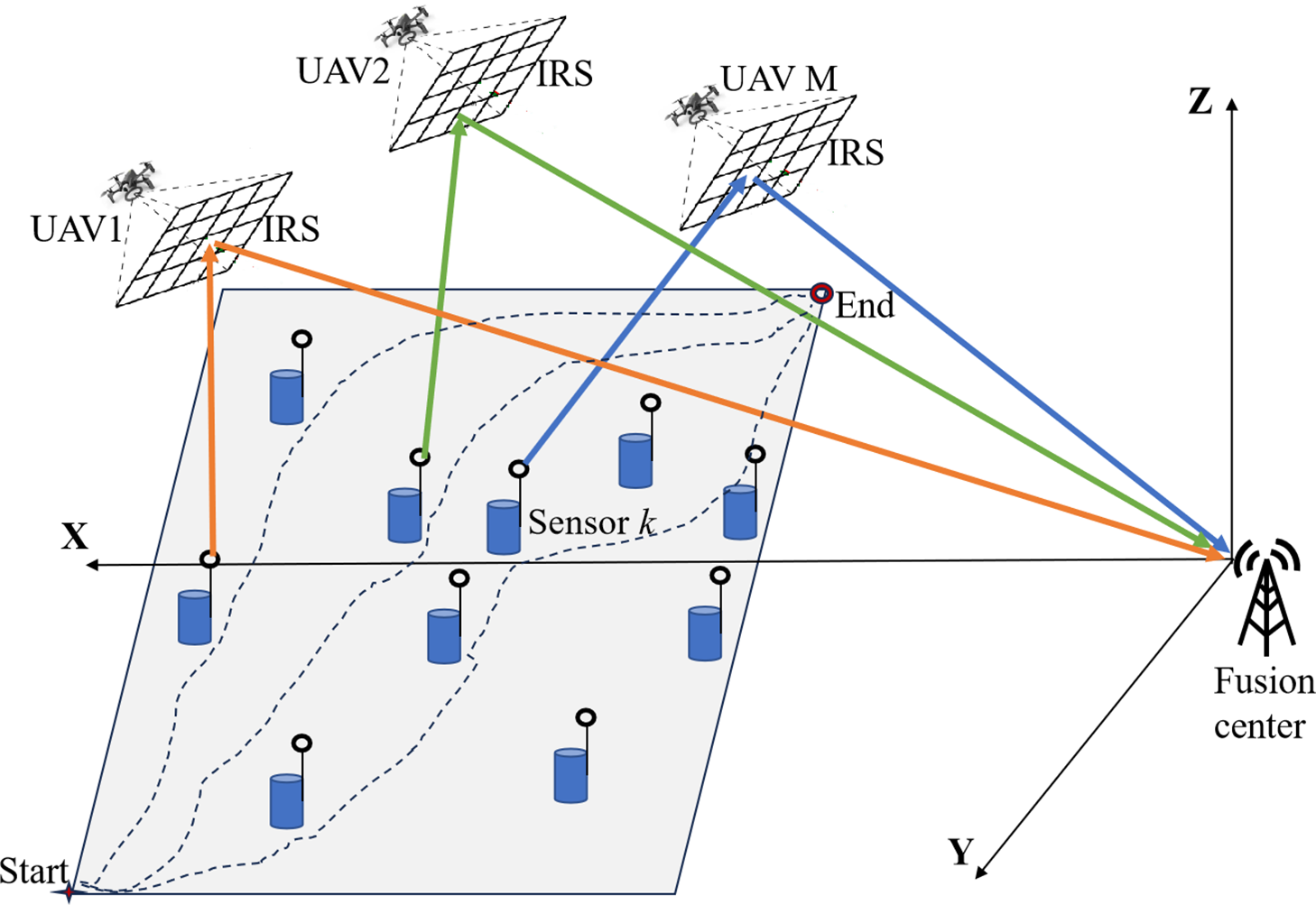
Figure 1: The multi-U-IRS-assisted IoT data collection model
This paper adopts the fly-hover-communicate protocol (FHCP) [33]: where UAVs utilize onboard IRS to assist in SN data collection only during hovering phases, while non-active SNs can enter a sleep mode [34], thereby extending the lifetime of IoT. Each U-IRS serves one sensor group, and each SN corresponds to a unique hovering point. After completing data collection at one hovering point, the UAV proceeds to the next one, e.g., the UAV
We define
For the SN
where
The instantaneous achievable rate corresponding to the SN
where B is the bandwidth allocated to the UAV
The SE is defined as
The total energy consumption of the system during UAVs-assisted service comprises the following components: the energy consumption for traveling of the UAVs, the total UAVs hovering energy consumption, the energy consumption of reflecting element in IRS for phase shifting, the energy consumption of SNs (including signal transmission and intrinsic circuit power), the intrinsic energy consumption of FC. The total energy consumption can be formulated as
The calculation methods for
The total energy consumption and EE of the system can be expressed as (5) and (6), respectively, where
In multi-U-IRS-assisted IoT data collection, the total mission completion time comprises two components: (1) The flight time of UAVs: The time required for UAVs to fly from the starting point, traverse all hovering points in sequence, and finally reach the endpoint. (2) The hovering time of UAVs: The time spent at each hovering point, during which the IRS in UAVs assists in transmitting SN signals to the FC. After completing data transmission from the associated SNs, UAVs terminates hovering and proceeds to the next hovering point immediately. Set
where
Let
Thus, the total task completion time can be expressed as [35]
As shown in (9), both
Unlike single-U-IRS-assisted IoT data collection, in multi-U-IRS-assisted IoT data collection, we must consider both maximizing EE and minimizing the total mission completion time to fully demonstrate the advantages of multi-UAV systems. Eqs. (6) and (9) reveal that EE and mission completion time are closely related to three optimization parameters: the SN-UAV association
Thus the problem of EE maximization is transformed into the minimization problem of
According to the above analysis, the problem can be formulated as a multi-objective optimization problem (P1).
Eq. (11c)–(11e) indicates the association between the UAV and SN. Eq. (11f) represents the constraint on the NoRE. It is the upper bound of the NoRE, which means that the number of allocated elements can not exceed the most NoRE that the UAV carried. Eq. (11g) defines the UAV trajectory’s start and end point constraints. Eq. (11h) indicates the energy budget constraint of the SN, where
Lemma 1: At the optimal solution to problem (P1), we have
Proof: Lemma 1 can be shown by contradiction. If there is an optimal solution
As revealed by Lemma 1, for (P1), the optimal hovering time in (P1) exactly matches the time required to complete data transmission from the SNs. Upon completing data collection, the UAV ceases hovering and proceeds to the next hovering point along a straight trajectory. We assume that all SNs have identical data upload requirements and the number of information bits that need to be collected from every SN is
As shown in the expression for EE in (6), the EE depends on the UAV-SN association
where
According to (P2) and (12),
(P2) is a constrained combinatorial optimization problem, where the objective function
To facilitate subsequent analysis, we expand and reorganize the mathematical expression of
Eq. (16) intuitively illustrates the correlation among UAV-SN association
The alternating optimization process proceeds as follows.
When the NoRE
The objective function of (P3) can be expanded as
As shown in (18), the minimization of the objective function in optimization problem (P3) corresponds to minimizing the flight distances of UAVs serving different SN groups, which constitutes a multiple Traveling Salesman Problem (m-TSP) with predetermined initial and final locations. Specifically, this involves multi-salesmen starting from predefined origins, each visiting a distinct subset of cities (where each city is visited exactly once by one salesman), and all salesmen ultimately arriving at predetermined destinations. The goal is to find the solution that minimizes the total travel distance. Since the m-TSP is NP-hard, optimization problem (P3) also falls into the NP-hard category. Consequently, genetic algorithm can obtain an efficient approximate solution for (P3).
When given the UAV-SN association
By expanding the objective function in (P4), we can get (20), which is shown at the bottom of page 9. Where
First, we select part (m, l) in (20) for analysis, subsequently extending the methodology to the aggregate sum of all parts. According to our prior work [38], when
Proof: See Appendix A.□
According to proposition 1, it can be seen that

From (21), it is evident that as a unimodal function, the peak of the unimodal function
Given UAV-SN association
Set
Eq. (23) reveals that
We consider using a convex optimization method to solve the hovering point
Then (24) can then be written as
To obtain the optimal solution of UAV hovering position
Based on the above analysis, we can formulate the minimization optimization problem of
After transformation,
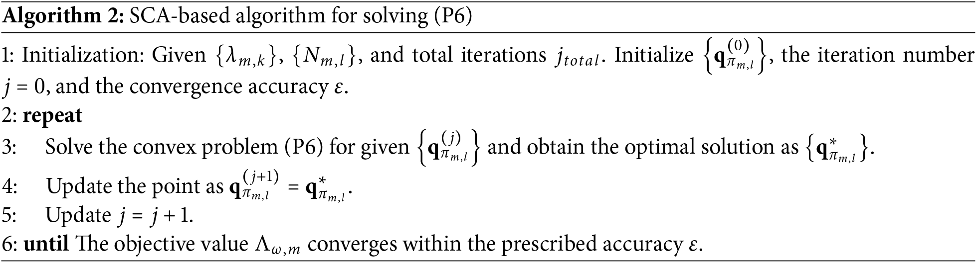
In Algorithm 2, we typically initialize the hovering points at positions directly above the SNs, then iteratively solve for their optimal locations. Once the hovering points are determined, the UAV departs from its starting point, sequentially visits the hovering points within its associated SN group, and finally proceeds to the endpoint, thereby generating its flight trajectory. Although (P6) specifically analyzes the portion associated with the UAV
According to (P6), the minimum value of
Based on the comprehensive analysis above, we propose an alternating optimization algorithm to solve (P2). The detailed procedure is outlined in Algorithm 3.
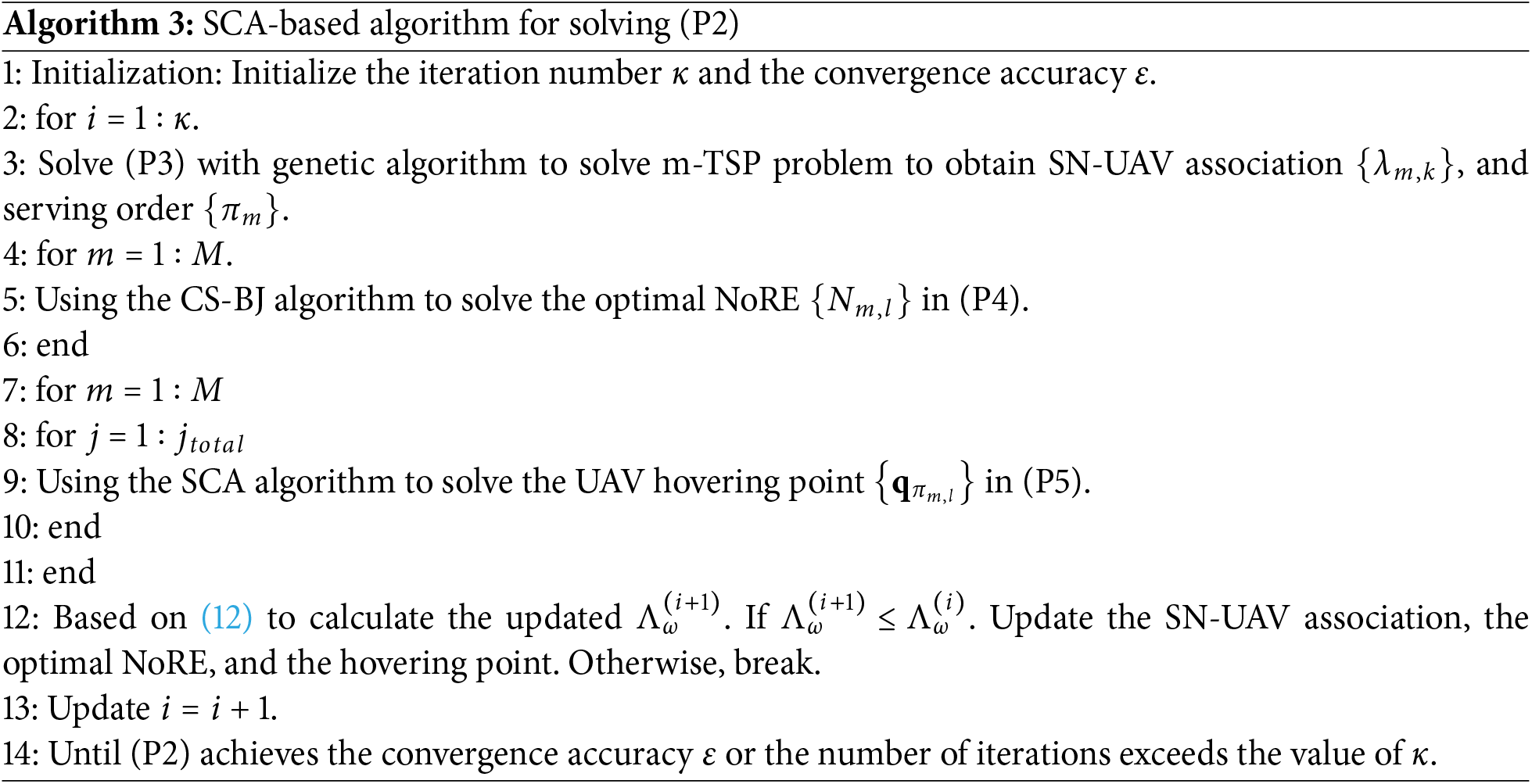
In Algorithm 3, the genetic algorithm, CS-BJ algorithm, and SCA algorithm all converge to a certain extent. Additionally, a break condition is implemented: once the optimized
The overall complexity of Algorithm 3 is determined by the complexities of sub-problems (P3)–(P5). For (P3), genetic algorithm is used to solve the m-TSP problem, with its complexity roughly
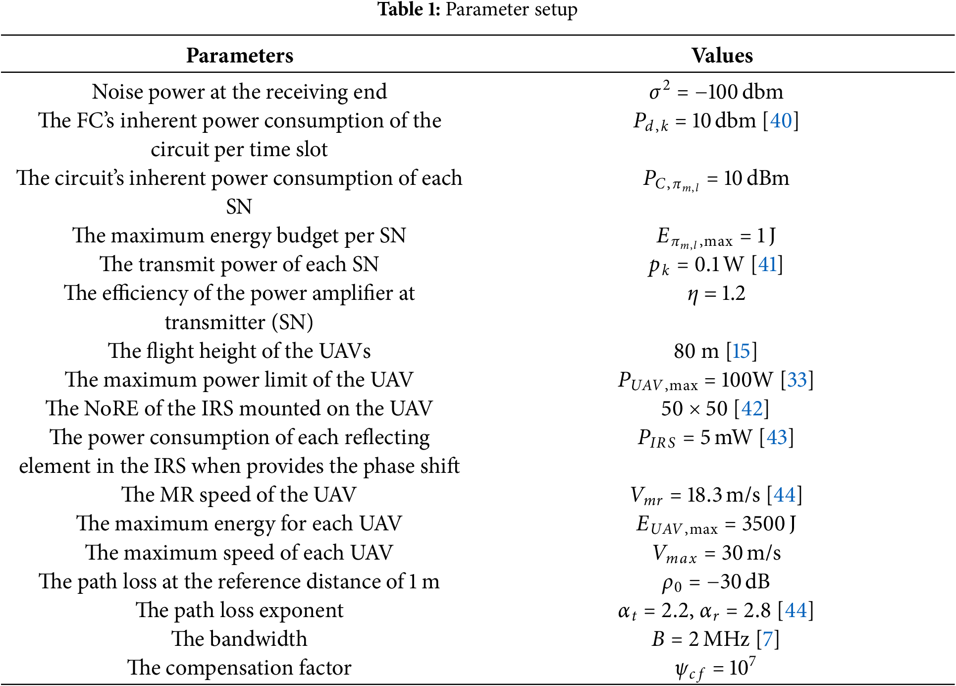
In this section, the proposed optimization strategy is compared with the static collection benchmark, where the wake-up time allocation and NoRE are optimized using the genetic algorithm and Algorithm 1, respectively. We assume there are
Four UAVs (
In this subsection, we first investigate the impact of varying transmission data amounts and weighting factors on the optimized trajectories and the required NoRE allocations. Subsequently, we evaluate how the weighting factor
Figs. 2 and 3 illustrate the optimized UAVs trajectories under varying transmission data amounts
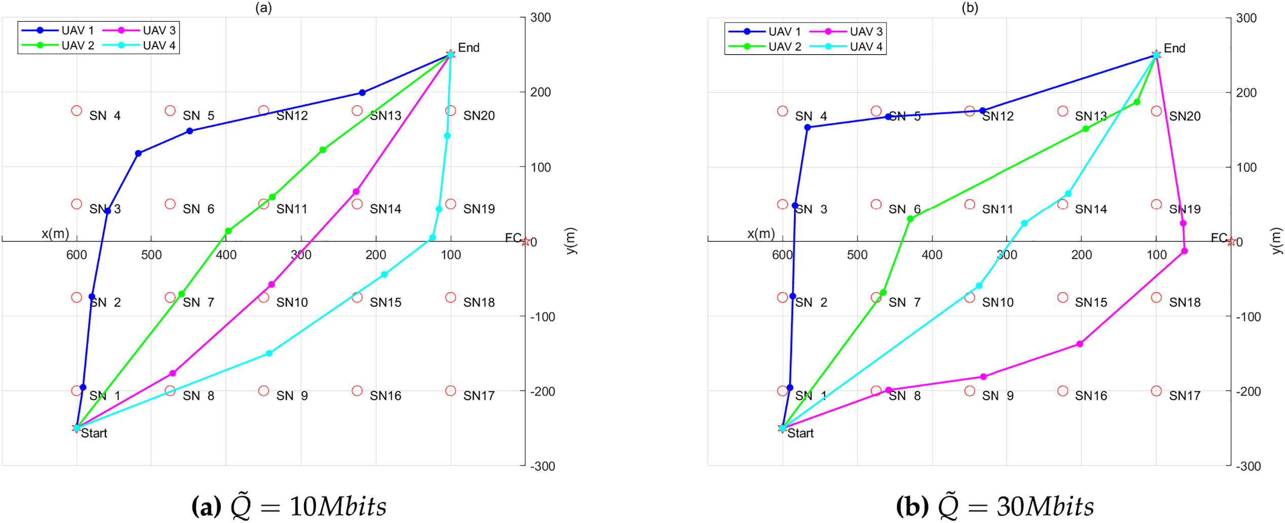
Figure 2: The optimized UAV trajectories with different data amounts
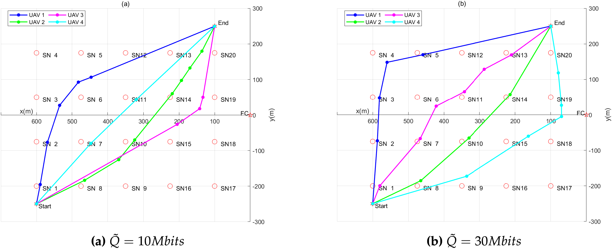
Figure 3: The optimized UAV trajectories with different data amounts
For the same
Fig. 4 illustrates the optimized NoREs under varying data transmission amounts
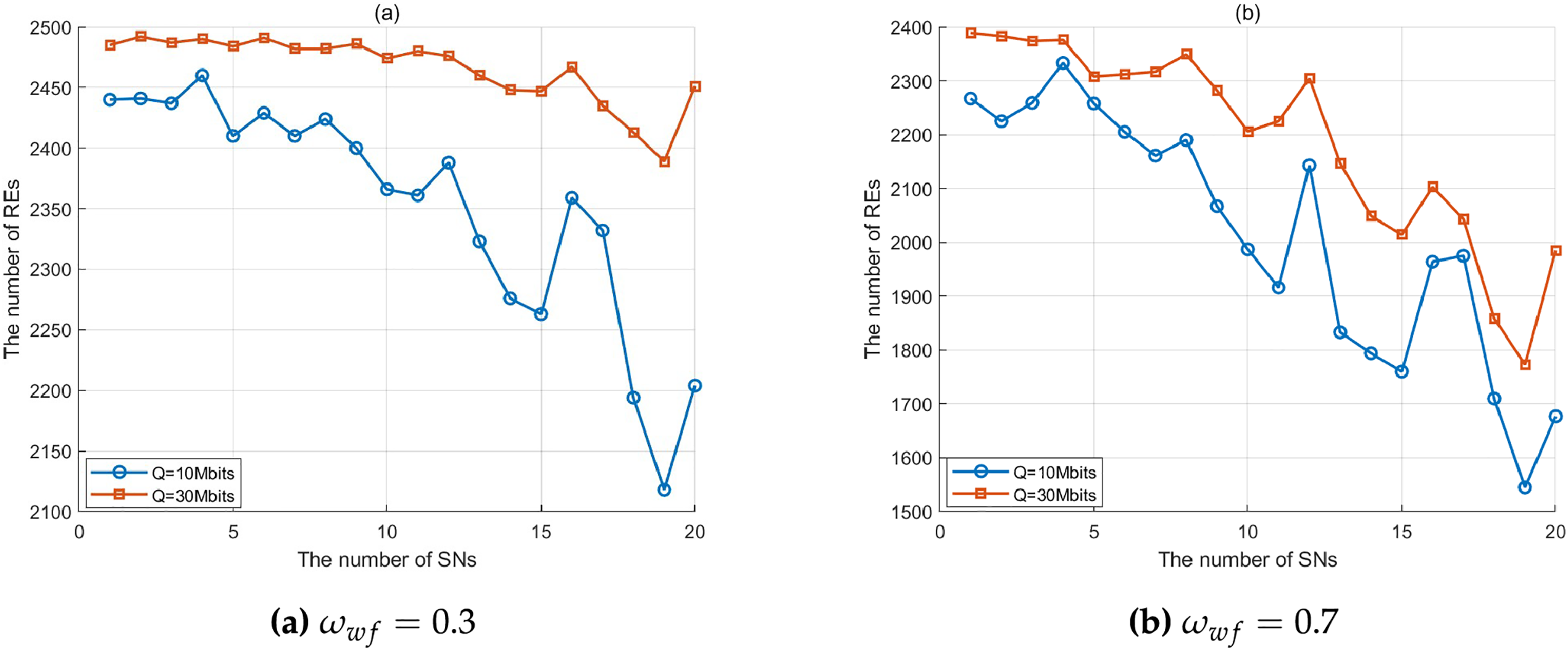
Figure 4: Optimized NoRE with different data amounts
Figs. 5 and 6 compare the EE and total mission completion time of the proposed scheme against the static collection benchmark under varying data transmission volumes
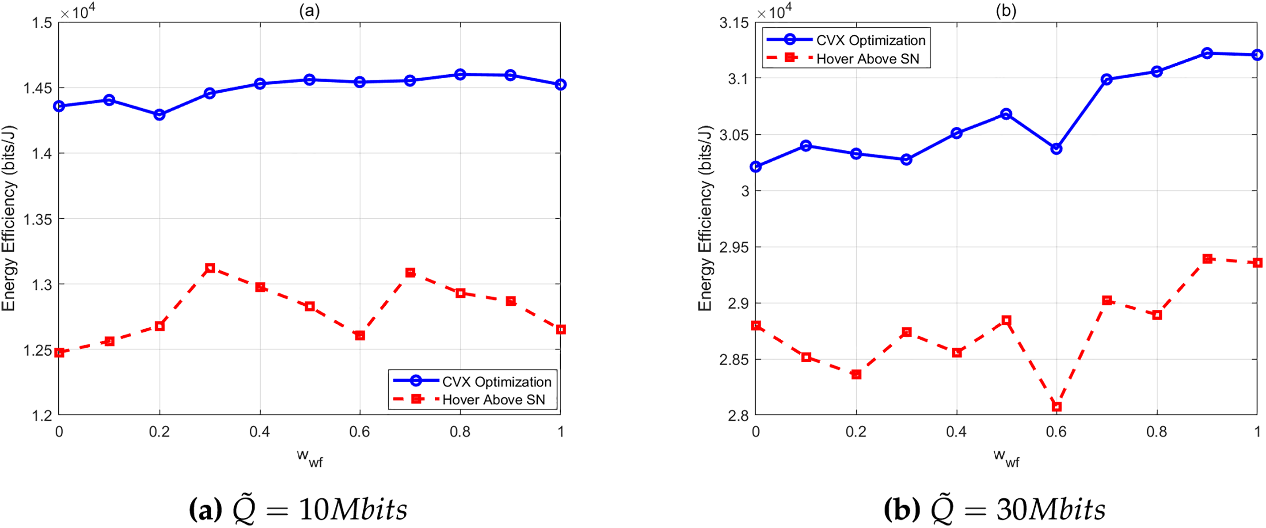
Figure 5: EE comparison of the two schemes with different
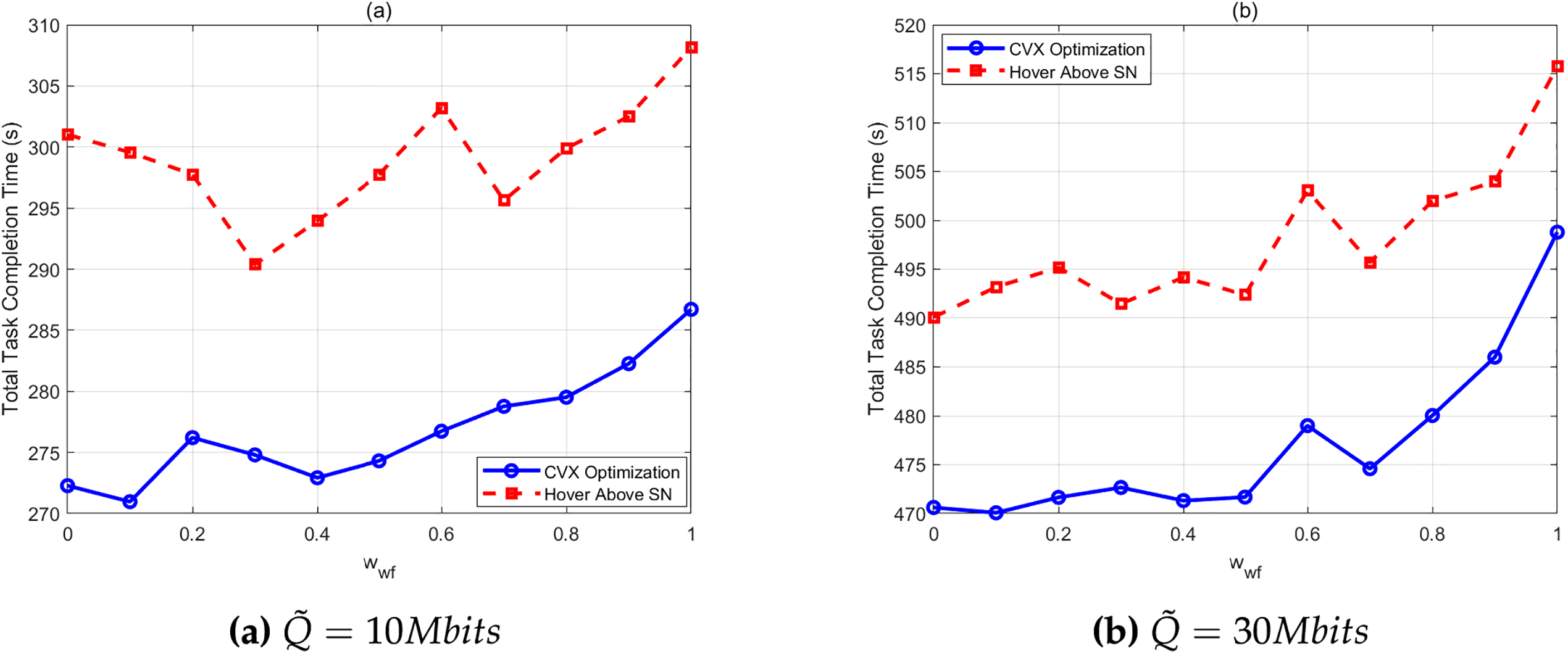
Figure 6: Total mission completion time comparison of the two schemes with different
A larger
Fig. 7 compares the weighted objective function
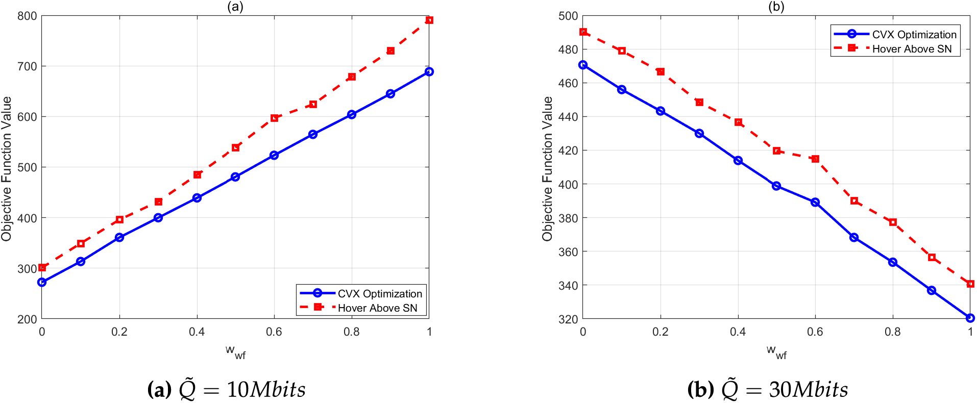
Figure 7: Comparison of
This paper investigates the fundamental tradeoff between EE and the total mission completion time for data collection in multi-U-IRS-assisted IoT. We analyze the expressions of EE and total mission completion time. To ensure consistency in optimization objectives, we first formulate an optimization problem that minimizes the reciprocal of EE and the total mission completion time. Subsequently, we propose minimizing the weighted sum of the reciprocal of EE and the total mission completion time. Due to the intractability of directly solving the original problem, we decompose it into three subproblems and develop an alternating algorithm for optimization. Specifically, a genetic algorithm is employed to optimize UAV-SN association, the CS-BJ algorithm is used to optimize the NoRE, and the SCA is applied to optimize UAVs trajectories. Simulation results demonstrate that, compared to the static collection benchmark, the proposed solution achieves higher EE, shorter total mission completion time, and smaller objective function values under varying data amounts, highlighting its superiority and effectiveness. This work provides practical implications for UAV deployment in real IoT scenarios. For instance, in cost-sensitive, periodic agricultural monitoring, an operator can set a high
For future research, it would be valuable to incorporate adaptive power control for the SNs, which could further enhance the EE and data rate of the system. In heterogeneous IoT applications, different SNs may exhibit significant variations in data generation rates due to their diverse monitoring task. Handling scenarios with heterogeneous data amounts represents a highly valuable research direction for the future, which will further enhance the universality of the proposed framework. A comprehensive empirical comparison between the proposed algorithm and a wider range of heuristic methods, including clustering and meta-heuristics, constitutes an important direction.
Acknowledgement: The authors would like to thank the Opening Project of Guangxi Wireless Broadband Communication and Signal Processing Key Laboratory, Key Laboratory of Cognitive Radio and Information Processing, Ministry of Education of China.
Funding Statement: This work was supported in part by the Opening Project of Guangxi Wireless Broadband Communication and Signal Processing Key Laboratory under Grant AD25069102; in part by the Basic Ability Improvement Project of Young and Middle Aged Teachers in Guangxi Universities, under Grant 2023KY0226; in part by Key Laboratory of Cognitive Radio and Information Processing, Ministry of Education of China, under Grant CRKL220108; in part by the Innovation Project of Guangxi Graduate Education, under Grant YCBZ2023131; in part by the Doctoral Research Foundation of Guilin University of Electronic Technology, under Grant UF23038Y; in part by the Bagui Youth Top Talent Project; in part by the Guangxi Key Research and Development Program under Grant AB25069510; in part by Open Fund of IPOC (BUPT), No. IPOC2024B07; in part by Guangxi Key Laboratory of Precision Navigation Technology and Application, under Grant DH202309.
Author Contributions: Hong Zhao: study conception and design, draft manuscript preparation; Hongbin Chen, Zhihui Guo: simulation setting, agricultural application scenario; Ling Zhan: analysis and interpretation of results; Shichao Li: paper discussion. All authors reviewed the results and approved the final version of the manuscript.
Availability of Data and Materials: No data and materials were used for the research described in the article.
Ethics Approval: Not applicable.
Conflicts of Interest: The authors declare no conflicts of interest to report regarding the present study.
We first analyze the variation of
1)
2) There always exists an optimized NoRE
When
Expanding both sides of inequality (A1) yields:
Since
Based on inequality (A3), we further obtain
The above analysis proves that
References
1. Nguyen K-V, Nguyen C-H, Do TV, Rotter C. Efficient multi-UAV assisted data gathering schemes for maximizing the operation time of wireless sensor networks in precision farming. IEEE Trans Ind Informat. 2023;19(12):11664–74. doi:10.1109/tii.2023.3248616. [Google Scholar] [CrossRef]
2. Jiao L, Gao L, Zheng J, Yang P, Xue W. Resource allocation in RISs-assisted UAV-enabled MEC network with computation capacity improvement. Comput Commun. 2024;228:107953. doi:10.1016/j.comcom.2024.107953. [Google Scholar] [CrossRef]
3. Huo X, Zhang H, Wang Z, Huang C, Yan H. Energy minimization for UAV-enabled data collection with guaranteed performance. IEEE Trans Veh Technol. 2024;73(12):19613–24. doi:10.1109/tvt.2024.3449639. [Google Scholar] [CrossRef]
4. Bakirci M. A novel swarm unmanned aerial vehicle system: incorporating autonomous flight, real-time object detection, and coordinated intelligence for enhanced performance. Trait Signal. 2023;40(5):2063–78. doi:10.18280/ts.400524. [Google Scholar] [CrossRef]
5. Kim C, Choi HH, Lee K. Joint optimization of trajectory and resource allocation for multi-UAV-enabled wireless-powered communication networks. IEEE Trans Commun. 2024;72(9):5752–64. doi:10.1109/tcomm.2024.3383113. [Google Scholar] [CrossRef]
6. Kang M, Jeon S-W. Energy-efficient data aggregation and collection for multi-UAV-enabled IoT networks. IEEE Wireless Commun Lett. 2024;13(4):1004–8. doi:10.1109/lwc.2024.3355934. [Google Scholar] [CrossRef]
7. Li M, He S, Li H. Minimizing mission completion time of UAVs by jointly optimizing the flight and data collection trajectory in UAV-enabled WSNs. IEEE Internet Things J. 2022;9(15):13498–510. doi:10.1109/jiot.2022.3142764. [Google Scholar] [CrossRef]
8. Zhan C, Zeng Y. Aerial-ground cost tradeoff for multi-UAV-enabled data collection in wireless sensor networks. IEEE Trans Commun. 2020;68(3):1937–50. doi:10.1109/tcomm.2019.2962479. [Google Scholar] [CrossRef]
9. Zhang H, Tao Y, Lv X, Liu Y. Leader follower UAV-assisted WSNs for improving data collection rate and shortening flight time. IEEE Sens J. 2023;23:26597–607. doi:10.1109/jsen.2023.3312733. [Google Scholar] [CrossRef]
10. Xu Y, Zhang T, Liu Y, Yang D, Xiao L, Tao M. 3D multi-UAV computing networks: computation capacity and energy consumption tradeoff. IEEE Trans Veh Technol. 2024;73:10627–41. doi:10.1109/tvt.2024.3372292. [Google Scholar] [CrossRef]
11. Jia R, Fu Q, Zheng Z, Zhang G, Li M. Energy and time trade-off optimization for multi-UAV enabled data collection of IoT devices. IEEE/ACM Trans Netw. 2024;32(6):5172–87. doi:10.1109/tnet.2024.3450489. [Google Scholar] [CrossRef]
12. Yuan X, Hu S, Ni W, Wang X, Jamalipour A. Deep reinforcement learning-driven reconfigurable intelligent surface-assisted radio surveillance with a fixed-wing UAV. IEEE Trans Inf Forensics Secur. 2023;18:4546–60. doi:10.1109/tifs.2023.3297021. [Google Scholar] [CrossRef]
13. Chen L, Wang Z. Multi-UAV trajectory planning for RIS-assisted SWIPT system under connectivity preservation. Comput Netw. 2024;255:110906. doi:10.1016/j.comnet.2024.110906. [Google Scholar] [CrossRef]
14. Zhang Q, Saad W, Bennis M. Reflections in the sky: millimeter wave communication with UAV-carried intelligent reflectors. In: 2019 IEEE Global Communications Conference (GLOBECOM); 2019 Dec 9–13; Waikoloa, HI, USA. p. 1–6. [Google Scholar]
15. Nguyen-Kha H, Nguyen HV, Le MTP, Shin OS. Joint UAV placement and IRS phase shift optimization in downlink networks. IEEE Access. 2022;10:111221–31. doi:10.1109/access.2022.3214663. [Google Scholar] [CrossRef]
16. You C, Kang Z, Zeng Y, Zhang R. Enabling smart reflection in integrated air-ground wireless network: IRS meets UAV. IEEE Wireless Commun. 2021;28(6):138–44. doi:10.1109/mwc.001.2100148. [Google Scholar] [CrossRef]
17. Peng Y, Tang J, Yang Q, Han Z, Ma J. Joint power allocation algorithm for UAV-borne simultaneous transmitting and reflecting reconfigurable intelligent surface-assisted non-orthogonal multiple access system. IEEE Access. 2023;11:140506–18. doi:10.1109/access.2023.3342049. [Google Scholar] [CrossRef]
18. Liu Y, Han F, Zhao S. Flexible and reliable multiuser SWIPT IoT network enhanced by UAV-mounted intelligent reflecting surface. IEEE Trans Rel. 2022;71(2):1092–103. doi:10.1109/tr.2022.3161336. [Google Scholar] [CrossRef]
19. Adam ABM, Ouamri MA, Wan X, Muthanna MSA, Alkanhel R, Muthanna A, et al. Secure communication in UAV–RIS-empowered multiuser networks: joint beamforming, phase shift, and UAV trajectory optimization. IEEE Syst J. 2024;18(2):1009–19. doi:10.1109/jsyst.2024.3379456. [Google Scholar] [CrossRef]
20. Dang X-T, Nguyen HV, Shin O-S. Physical layer security for IRS-UAV-assisted cell-free massive MIMO systems. IEEE Access. 2024;12:89520–37. doi:10.1109/access.2024.3419888. [Google Scholar] [CrossRef]
21. Nnamani CO, Khandaker MR, Sellathurai M. Secure data collection via UAV-carried IRS. ICT Express. 2023;9(4):706–13. doi:10.1016/j.icte.2022.09.003. [Google Scholar] [CrossRef]
22. Tyrovolas D, Mitsiou NA, Boufikos TG, Mekikis P-V, Tegos SA, Diamantoulakis PD, et al. Energy-aware trajectory optimization for UAV-mounted RIS and full-duplex relay. IEEE Internet Things J. 2024;11(13):24259–72. doi:10.1109/jiot.2024.3390767. [Google Scholar] [CrossRef]
23. Tyrovolas D, Mekikis P-V, Tegos SA, Diamantoulakis PD, Liaskos CK, Karagiannidis GK. Energy-aware design of UAV-mounted RIS networks for IoT data collection. IEEE Trans Commun. 2023;71(2):1168–78. doi:10.1109/tcomm.2022.3229672. [Google Scholar] [CrossRef]
24. Mohamed EM, Hashima S, Hatano K. Energy aware multi-armed bandit for millimeter wave-based UAV mounted RIS networks. IEEE Wireless Commun Lett. 2022;11(6):1293–7. doi:10.1109/lwc.2022.3164939. [Google Scholar] [CrossRef]
25. Zeng Y, Zhang R. Energy-efficient UAV communication with trajectory optimization. IEEE Trans Wireless Commun. 2017;16(6):3747–60. doi:10.1109/twc.2017.2688328. [Google Scholar] [CrossRef]
26. Xiao Y, Tyrovolas D, Tegos SA, Diamantoulakis PD, Ma Z, Hao L, et al. Solar powered UAV-mounted RIS networks. IEEE Commun Lett. 2023;27(6):1565–9. doi:10.1109/lcomm.2023.3264493. [Google Scholar] [CrossRef]
27. Yang H, Lin K, Xiao L, Zhao Y, Xiong Z, Han Z. Energy harvesting UAV-RIS-assisted maritime communications based on deep reinforcement learning against jamming. IEEE Trans Wireless Commun. 2024;23(8):9854–68. doi:10.1109/twc.2024.3367034. [Google Scholar] [CrossRef]
28. Mamaghani MT, Hong Y. Aerial intelligent reflecting surface-enabled Terahertz covert communications in beyond-5G Internet of Things. IEEE Internet Things J. 2022;9(19):19012–33. doi:10.1109/jiot.2022.3163396. [Google Scholar] [CrossRef]
29. Ge L, Zhang H, Wang J-B, Li GY. Reconfigurable wireless relaying with multi-UAV-carried intelligent reflecting surfaces. IEEE Trans Veh Technol. 2023;72(4):4932–47. doi:10.1109/tvt.2022.3227623. [Google Scholar] [CrossRef]
30. Liao Y, Song Y, Xia S, Han Y, Xu N, Zhai X. Energy minimization of RIS-assisted cooperative UAV-USV MEC network. IEEE Internet Things J. 2024;11(20):32490–502. doi:10.1109/jiot.2024.3432151. [Google Scholar] [CrossRef]
31. Van Vinh N. Performance enhancement of nonorthogonal multiple access systems by multiple UAVs and RISs. Digit Signal Process. 2023;140:104136. doi:10.1016/j.dsp.2023.104136. [Google Scholar] [CrossRef]
32. Sun S, Zhang G, Mei H, Wang K, Yang K. Optimizing multi-UAV deployment in 3-D space to minimize task completion time in UAV-enabled mobile edge computing systems. IEEE Commun Lett. 2020;25(2):579–83. doi:10.1109/lcomm.2020.3029144. [Google Scholar] [CrossRef]
33. Zeng Y, Xu J, Zhang R. Energy minimization for wireless communication with rotary-wing UAV. IEEE Trans Wireless Commun. 2019;18(4):2329–45. doi:10.1109/twc.2019.2902559. [Google Scholar] [CrossRef]
34. Shen S, Yang K, Wang K, Zhang G, Mei H. Number and operation time minimization for multi-UAV-enabled data collection system with time windows. IEEE Internet Things J. 2022;9(12):10149–61. doi:10.1109/jiot.2021.3121511. [Google Scholar] [CrossRef]
35. Zhan C, Zeng Y. Completion time minimization for multi-UAV-enabled data collection. IEEE Trans Wireless Commun. 2019;18(10):4859–72. doi:10.1109/twc.2019.2930190. [Google Scholar] [CrossRef]
36. Shang B, Shafin R, Liu L. UAV swarm-enabled aerial reconfigurable intelligent surface: modeling, analysis, and optimization. IEEE Trans Commun. 2023;71(6):3621–36. doi:10.1109/tcomm.2022.3173369. [Google Scholar] [CrossRef]
37. Mustaghfirin M, Singh K, Biswas S, Huang W-J. Performance analysis of intelligent reflecting surface-assisted multi-users communication networks. Electronics. 2021;10(17):2084. doi:10.3390/electronics10172084. [Google Scholar] [CrossRef]
38. Zhao H, Chen H, Tan F, Zhan L. Optimum number of reflecting elements for UAV mounted intelligent reflecting surface-assisted data collection in wireless sensor network. IEEE Sens J. 2024;24(14):23062–74. doi:10.1109/jsen.2024.3407771. [Google Scholar] [CrossRef]
39. Zhao H, Chen H, Li S, Zhan L. Joint Optimization of UAV trajectory and number of reflecting elements for UAV-mounted intelligent reflecting surface-assisted data collection in wireless sensor networks under transmission prioritized scheme. IEEE Trans Green Commun Netw. 2021;10:276–80. doi:10.1109/lwc.2020.3027969. [Google Scholar] [CrossRef]
40. Li D. How many reflecting elements are needed for energy- and spectral-efficient intelligent reflecting surface-assisted communication. IEEE Trans Commun. 2022;70(2):1320–31. doi:10.1109/tcomm.2021.3128544. [Google Scholar] [CrossRef]
41. Zhan C, Zeng Y, Zhang R. Energy-efficient data collection in UAV enabled wireless sensor network. IEEE Wirel Commun Lett. 2018;7(3):328–31. doi:10.1109/lwc.2017.2776922. [Google Scholar] [CrossRef]
42. Tang W, Li X, Dai JY, Jin S, Zeng Y, Cheng Q, et al. Wireless communications with programmable metasurface: transceiver design and experimental results. China Commun. 2019;16(5):46–61. doi:10.23919/j.cc.2019.05.004. [Google Scholar] [CrossRef]
43. Nguyen NT, Vu Q-D, Lee K, Juntti M. Hybrid relay-reflecting intelligent surface-assisted wireless communications. IEEE Trans Veh Technol. 2022;71(6):6228–44. doi:10.1109/tvt.2022.3158686. [Google Scholar] [CrossRef]
44. Ren H, Zhang Z, Peng Z, Li L, Pan C. Energy minimization in RIS-assisted UAV-enabled wireless power transfer systems. IEEE Internet Things J. 2023;10(7):5794–809. doi:10.1109/jiot.2022.3150178. [Google Scholar] [CrossRef]
Cite This Article
 Copyright © 2026 The Author(s). Published by Tech Science Press.
This work is licensed under a Creative Commons Attribution 4.0 International License , which permits unrestricted use, distribution, and reproduction in any medium, provided the original work is properly cited.
 Downloads
 Citation Tools