
 Submit a Paper
 Propose a Special lssue
 Open Access
ARTICLE
Dragonfang: An Open-Source Embedded Flight Controller with IMU-Based Stabilization for Quadcopter Applications
Department of Electronic Devices, Circuits and Architectures, Faculty of Electronics, Telecommunications and Information Technology, National University of Science and Technology Politehnica Bucharest, Bucharest, 060042, Romania
* Corresponding Author: Georgian Nicolae. Email:
Computers, Materials & Continua 2026, 87(1), 13 https://doi.org/10.32604/cmc.2025.072749
Received 02 September 2025; Accepted 23 December 2025; Issue published 10 February 2026
 View Full Text
 Download PDF
Abstract
Unmanned aerial vehicles (UAVs), especially quadcopters, have become indispensable in numerous industrial and scientific applications due to their flexibility, low cost, and capability to operate in dynamic environments. This paper presents a complete design and implementation of a compact autonomous quadcopter capable of trajectory tracking, object detection, precision landing, and real-time telemetry via long-range communication protocols. The system integrates an onboard flight controller running real-time sensor fusion algorithms, a vision-based detection system on a companion single-board computer, and a telemetry unit using Long Range (LoRa) communication. Extensive flight tests were conducted to validate the system’s stability, communication range, and autonomous capabilities. Potential applications in law enforcement, agriculture, search and rescue, and environmental monitoring are also discussed.Keywords
Abbreviations
| BPSK | Binary Phase-Shift Keying |
| BLDC | Brushless Direct Current |
| CEP | Circular Error Probability |
| DShot | Digital ESC Protocol |
| DMA | Direct Memory Access |
| EMF | Electromotive Force |
| ESC | Electronic Speed Controller |
| FOC | Field-Oriented Control |
| FSK | Frequency-Shift Keying |
| GPIO | General-Purpose Input/Output |
| GPS | Global Positioning System |
| IC | Integrated Circuit |
| IMU | Inertial Measurement Unit |
| LiDAR | Light Detection and Ranging |
| LiPo | Lithium-Polymer |
| LoRa | Long Range (LPWAN Protocol) |
| LPWAN | Low-Power Wide-Area Network |
| MARG | Magnetic, Angular Rate and Gravity |
| MCU | Microcontroller Unit |
| MEMS | Micro-Electro-Mechanical Systems |
| MSK | Minimum Shift Keying |
| NMEA | National Marine Electronics Association |
| OLED | Organic Light-Emitting Diode |
| PCB | Printed Circuit Board |
| PID | Proportional–Integral–Derivative |
| RF | Radio Frequency |
| R-CNN | Region-Based Convolutional Neural Network |
| SPI | Serial Peripheral Interface |
| TCXO | Temperature-Compensated Crystal Oscillator |
| ToF | Time-of-Flight |
| UART | Universal Asynchronous Receiver/Transmitter |
| UAV | Unmanned Aerial Vehicle |
| YOLO | You Only Look Once |
| ZCD | Zero-Cross Detector |
Within this context, the project Dragonfang: An Open-Source Embedded Flight Controller with IMU-Based Stabilization for Quadcopter Applications aims to provide a modular and open-source solution for quadcopter stabilization and control. The system employs an Inertial Measurement Unit (IMU)-based stabilization mechanism, ensuring accurate attitude estimation and reliable flight dynamics control. In addition, the platform integrates vision-based object detection and long-range LoRa telemetry, which are critical for autonomous navigation and extended-range communication in outdoor or industrial scenarios.
Recent studies emphasize the need for open-source flight controllers in the UAV domain, facilitating rapid prototyping, flexibility in design, and lower development costs [1]. Advanced control algorithms such as higher-order sliding modes and nonlinear model predictive control have been extensively investigated to improve quadcopter trajectory tracking, robustness to disturbances, and overall flight accuracy [2,3]. The Dragonfang controller builds upon these principles by fusing real-time sensor data from the IMU to enhance stability and responsiveness under varying flight conditions. Vision-based object detection has also become an essential feature in UAV systems, enabling functionalities like obstacle avoidance, target tracking, and precision landing. Techniques based on deep learning models, including YOLOv8 and Mask Region-Based Convolutional Neural Network (R-CNN), have demonstrated high accuracy and real-time performance in embedded platforms suitable for UAVs [4,5]. Furthermore, precision landing capabilities employing Kalman filters and disturbance observers contribute to improved landing accuracy, which is crucial for autonomous docking or recharging operations [6,7]. For reliable long-range communication, low-power wide-area network (LPWAN) technologies such as LoRa have emerged as attractive solutions, offering extended coverage with minimal energy consumption. LoRa-based telemetry systems have proven effective in maintaining UAV communication links over distances exceeding conventional radio frequency modules [8,9]. Dragonfang integrates such communication modules to support mission-critical data exchange during extended flight operations.
Potential applications of this platform extend beyond academic prototyping, including precision agriculture, search-and-rescue operations, and environmental monitoring, all of which benefit from the long-range communication and modular sensing capabilities of the proposed design.
This project addresses key challenges in UAV system integration by delivering a complete quadcopter platform with the following contributions:
1. Integrated Mechanical and Electronic Design: Development of a custom frame and dedicated Printed Circuit Boards (PCBs) to support flight control, perception, and telemetry, optimized for compactness and efficiency.
2. Onboard Flight Control and Navigation: Implementation of real-time flight stabilization and waypoint tracking on the microcontroller using IMU and GPS data, with sensor fusion and control loops supporting both manual and autonomous operation.
3. Vision-Based Perception and Efficient Telemetry: Integration of a camera-equipped single-board computer for object and landing pad detection, alongside a custom telemetry system ensuring real-time data transfer and onboard logging for post-flight analysis.
This paper is structured as follows. Section 2 presents the mathematical modeling of the quadcopter dynamics, including the derivation of the governing equations and the assumptions made in the system representation. Section 3 describes the control strategies employed for attitude and position stabilization, emphasizing IMU-based control loops. Section 4 outlines the electrical design of the system, detailing the selection and integration of components such as the microcontroller, sensors, and communication modules. Section 5 covers the mechanical design, focusing on the frame structure, motor arrangement, and payload distribution. Section 6 discusses the software design, including the development of firmware, vision-based object detection algorithms, and LoRa communication protocols. Finally, Section 8 concludes the paper by summarizing the main contributions and highlighting directions for future research and system improvements.
To address the integration of orientation estimation algorithms and trajectory control for ensuring stability and precise control in quadcopter systems, it is essential to understand both sensor fusion techniques for position and orientation estimation, and the use of Proportional-Integral-Derivative (PID) control loops for trajectory maintenance. PID control loops are fundamental for correcting deviations and maintaining the desired trajectory, ensuring stability and precise navigation of the quadcopter [10]. Meanwhile, sensor fusion algorithms, such as the Madgwick filter, combine data from accelerometers, gyroscopes, and magnetometers to provide a stable and accurate orientation estimation [11]. The integration of these two components, sensor fusion for positioning and PID control for trajectory regulation, is crucial for performance in complex environments, as highlighted in recent studies on indoor localization and control of quadcopters [12].
A PID control loop is a widely used feedback control system employed to maintain a desired setpoint in dynamic systems. The PID controller adjusts a control input based on the error, which is the difference between the system’s current output and the desired setpoint. As its name implies, the PID output is the summation of the following terms:
The proportional control provides a corrective action that is directly related to the magnitude of the error. It is calculated as:
where:
•
•
•
However, using only it alone can lead to a steady-state error or oscillation around the setpoint, especially when the system is subjected to external disturbances.
The integral control is used in order to eliminate the steady-state error introduced by the proportional control, by numerically integrating the error over time:
where:
•
•
•
• T is the current time (upper integration limit).
A too high integral value can lead to oscillations in the system due to high I value when the error crosses the zero point, effect also known as integral windup. This effect can be eliminated by either limiting the integral value within a specific range or setting it to zero when the system error sign changes.
The purpose of the derivative control is to reduce the rate at which the correction occurs and is calculated as follows:
where:
•
•
•
An important aspect is in case that the system error contains noise, a too high derivative coefficient causes the noise to be added to the output with a high amplitude, which in the case of quadcopter motor control results in aggressive shaking, causing unnecessarily high current consumption.
The Madgwick Filter is a sensor fusion method which uses a MARG sensor array (Magnetic, Angular Rate and Gravity) in order to estimate the quaternion representation of its orientation in a reference system of coordinates. A gyroscope measures angular velocity which, if initial conditions are known, may be integrated over time to compute the sensor’s orientation. However, many applications use a MEMS (Micro Electrical Mechanical System) type of gyroscope due to its small size and low cost, which is not accurate: besides the initial bias on each axis of measurement, there is also a bias drift component, resulting in less accurate orientation estimation by gyroscope angular velocity integration alone over time. The Madgwick Filter works by estimating the angular velocity quaternion as reference from the accelerometer (and magnetometer) readings by using the gradient descent algorithm on an objective function, which is then used in order to calculate the current bias of the angular velocity measurement performed by the gyroscope. Then this bias is integrated over time in order to estimate the gyroscope bias drift. Finally, the estimated bias drift is subtracted from the gyroscope angular rate measurement and the result is also integrated over time in order to obtain the sensor orientation relative to the reference system of coordinates.
Filter derivation
Angular velocity (
where:
•
•
• The leading 0 represents the scalar part of the quaternion (zero for pure angular velocity vectors).
Quaternion derivative describing the rate of change of orientation of the earth frame relative to the sensor frame:
where:
•
•
•
•
Quaternion orientation estimation at step
Objective function for finding the quaternion which aligns the predefined direction of a reference field in the Earth frame to the measured one (
where (
For example, in the case that
Gyroscope current bias estimation:
Gyroscope total bias estimation (accumulated bias drift), with gain
Compensated angular velocity estimation:
Finally, the compensated angular velocity estimation (with the removed bias drift computed using the accelerometer and/or magnetometer readings) is integrated over time in order to obtain the sensor orientation in the reference system of coordinates.
The quadcopter structure is presented in the Fig. 1, including the corresponding angular velocities, torques and forces created by the four rotors (numbered from 1 to 4). For each rotor-propeller pair, depending on the angular velocity
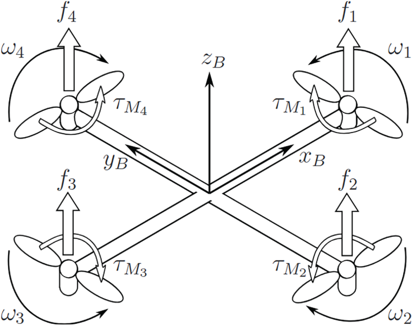
Figure 1: Forces acting upon the quadcopter frame. Source: https://github.com/AngeloEspinoza/quadrotor-model-and-control
In order to have effective yaw angle control (around the
where:
•
•
•
•
•
where:
•
•
• The summation is taken over all four motors (
To address the mechanical setup and control dynamics of quadcopters, including the angular velocities, torques, and forces generated by the rotor-propeller pairs, several studies provide detailed insights. Bucki and Mueller [13] present a novel quadcopter design with passive rotary joints, discussing dynamics and control mechanisms involving angular velocities and torques generated by the propellers, emphasizing their importance for controlling orientation and translation. César et al. [14] provide mathematical modeling of rotor forces and torques, underlining the precision required for stability and control. Furthermore, Bin Junaid et al. [11] explore dual-axis tilting quadcopters and the management of angular velocities and torques for effective orientation and positional control, which is essential for full drone maneuverability.
Advantages over traditional algorithms: Unlike classical PID-only flight controllers, the proposed system integrates the Madgwick filter for real-time quaternion-based orientation estimation, which reduces drift and improves accuracy in attitude control. Additionally, the dual-IMU setup provides redundant sensing and averaging, thereby lowering the influence of sensor noise and vibrations compared to single-IMU systems. The result is a more stable and responsive flight behavior, particularly under dynamic conditions such as wind disturbances or rapid maneuvering.
Multi-Sensor Fusion
Accurate and robust flight control requires the combination of multiple sensors, each with complementary strengths. In the Dragonfang platform, accelerometer and gyroscope data from two independent IMUs are fused using the Madgwick algorithm, which computes quaternion-based orientation estimates in real time. The dual-IMU approach reduces noise sensitivity and provides redundancy, ensuring that a single faulty reading does not destabilize the system. Additional sensors, including a GPS receiver, a barometric pressure sensor, and a Time-of-Flight (ToF) distance sensor, are incorporated through weighted averaging and complementary filtering. This fusion strategy enables the system to maintain accurate attitude estimation while also providing reliable altitude and position feedback, which are critical for stable hovering and autonomous flight modes.
The main electronics module of the Dragonfang quadcopter consists of two custom-designed Printed Circuit Boards (PCBs), developed by the team and stacked vertically to minimize space while maintaining high performance. The larger PCB, referred to as the Main Board, contains the motor drivers and power supply components (Fig. 2). The smaller PCB, known as the Flight Controller Board, is mounted on top of the Main Board and manages throttle signaling and flight logic implementation (Fig. 3).
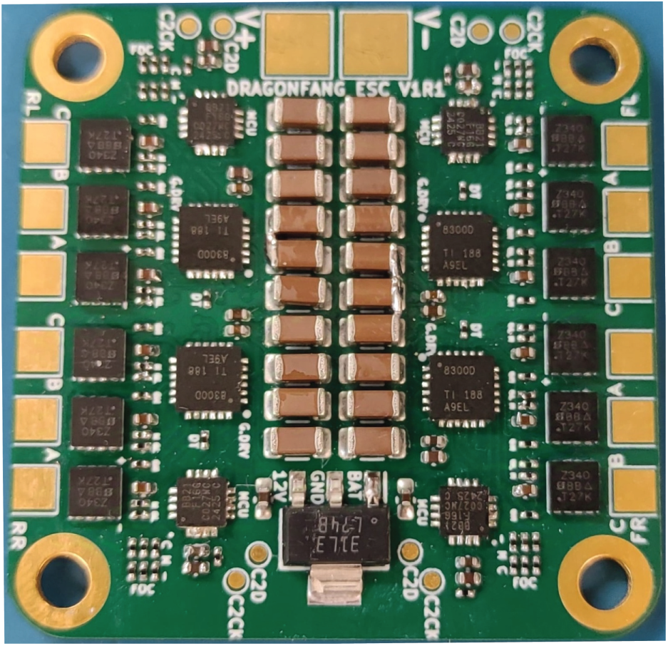
Figure 2: Assembled main board (bottom layer of the electronics stack)
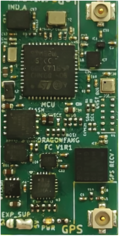
Figure 3: Assembled flight controller board (top layer of the electronics stack)
The Main Board contains the Brushless Direct Current motor (BLDC) Electronic Speed Controllers (ESCs), the main +5 V DC power supply circuit using a buck converter IC supporting up to 5 A load current and 36 V input, making it useful for powering other electrical components besides the critical ones, such as Light Detection and Ranging (LiDAR) sensors or servo motors. It also has a +12 V regulator for the ESCs supporting up to 26 V input with up to 60 V transients (for max. 100 ms), making the whole system rated for Lithium-Polymer or Lithium-Ion battery packs consisting of 2 to 6 cells in series, making it suitable for a large variety of quadcopter sizes or brushless motor configurations. The PCB also contains the power supply input pads, four M3 mounting holes, the Flight Controller Module footprint and the programming, debug and expansion ports, allowing for external modules to be powered and interfaced with the Flight Controller.
The PCB has 45 mm
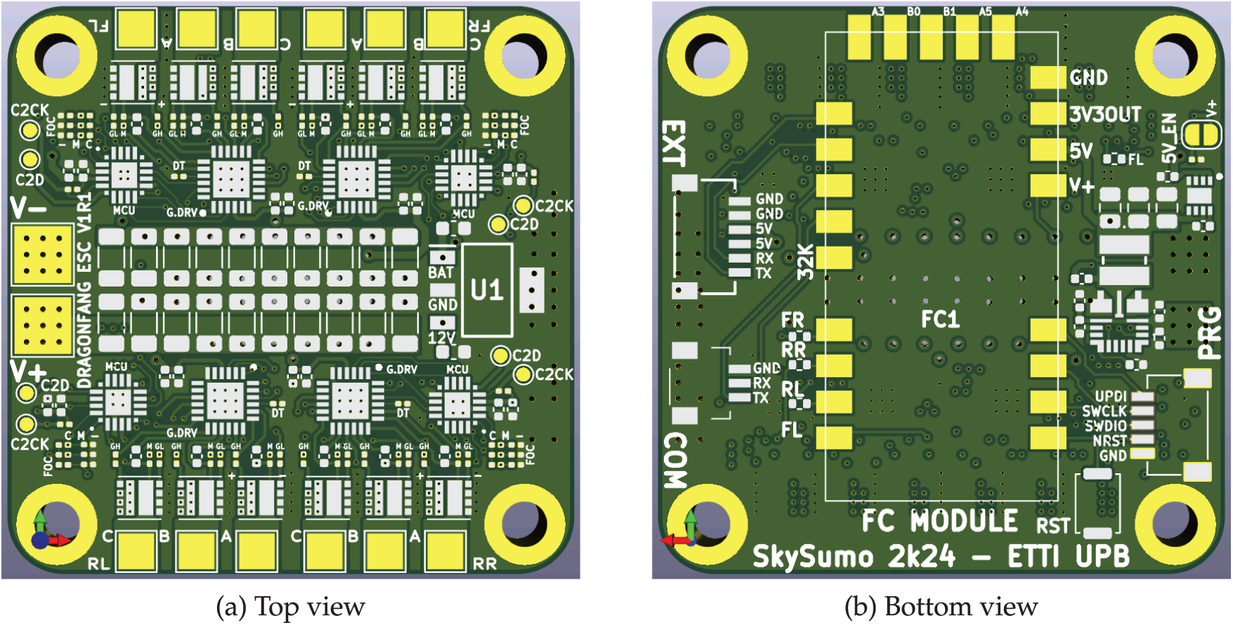
Figure 4: Top and bottom PCB views of the main board
The board contains four field-oriented control (FOC) brushless DC motor (BLDC) electronic speed controllers (ESC) which drive the quadcopter propeller motors and take the Flight Controller output throttle digital signals as input. Each ESC circuit contains:
• Microcontroller: 8051-based EFM8BB2 model. Runs the motor driver firmware, accepting motor throttle values with 2000 subdivisions, over the “DShot300” digital protocol.
• N-MOSFET Gate Driver IC: Up to 260 ns gate drive dead-time, drives 3 N-MOSFET pairs (high-side and low-side) and integrates high-side bootstrap diodes. The IC high-side power supply is connected to the on-board 12 V regulator output, in order to avoid exceeding the maximum Gate-Source voltage of the MOSFETs in case of main supply voltage spikes or high DC input voltage, for example from using LiPo batteries having 6 cells connected in series.
• 3 Dual-Channel N-MOSFETs: 30 A/40 A max. continuous
• Motor phase voltage dividers: Used by the microcontroller in order to detect the current motor phase based on the back electromotive force.
• Gate resistors: For adjusting the N-MOSFET gate charge time and limiting the charge current within the driver IC limits.
For the control side, the micrcocontrollers were programmed with the open-source “Bluejay” ESC firmware. The Microcontroller Unit (MCU) has General-Purpose Input/Output (GPIO) pins used for controlling the High and Low motor phase MOSFET gates (3x low and high side control pins), along with analog input pins connected to the motor phases via voltage dividers in order to reduce the motors’ back EMF to a voltage which is safe for the microcontrollers (and M_A/B/C/COM_SENSE). These pins are connected to the internal Zero-Cross-Detector (ZCD) peripheral and are used by the firmware for the motor feedback loop in detecting the current phase in order to drive the appropriate MOSFETs at each time step.
The MOSFET driver IC drives the high-side MOSFETs with a bootstrap circuit (Fig. 5), making use of just a diode and a capacitor to drive the high-side transistor at an optimal Gate-Source voltage, regardless of the back-EMF on the respective phase contact. Its principle works as follows: at each cycle, the low-side N-MOSFET is “turned on” by the MOSFET driver on the left side of the figure above, by applying the positive supply voltage on the Gate Pin, therefore charging the Gate to a high enough voltage with respect to ground, this way “connecting” the capacitor negative terminal to the ground. A positive voltage potential between the positive and negative capacitor terminals is formed, allowing it to charge through the diode, reaching a voltage close to the driver positive power supply voltage.
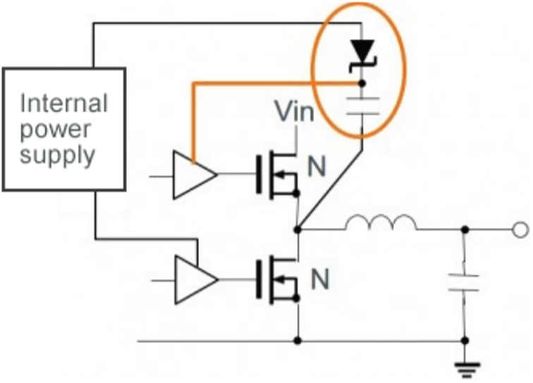
Figure 5: High-side N-MOSFET bootstrap circuit for driving brushless DC motor phases efficiently. Source: https://techweb.rohm.com
Later in the cycle, the high-side MOSFET needs to “turn on”. In the case that the voltage over the motor coil is close to zero, a high enough Gate-Source voltage is generated and the transistors activates with no problem. Without the bootstrap circuit, when the voltage over the coil rises, for example, close to the main power supply voltage (equivalent to the Back-EMF of the BLDC motor running at high speed), the Gate-Drain voltage on the High-Side MOSFET decreases, resulting in higher Drain-Source resistance, higher power dissipation and lower motor current. But when the bootstrap circuit is used, the High-side MOSFET is turned on via the voltage stored across the capacitor plates, which will be always close to the main supply voltage, provided that the low-side MOSFET was turned on not too long ago in order to allow the capacitor to discharge. This way, there is much lower power loss in the MOSFET at high switching frequency. Given this principle of operation, the N-Channel MOSFET bootstrap circuit works properly only in the case of ON-OFF inductive load control switching applications. Also, the capacitor value must be chosen by taking into account the parasitic resistance, as well as the required time to have the high-side MOSFET turned “ON” in order to not have it discharge before the low-side switching phase starts.
Core Advantages of the Main Board: Unlike traditional off-the-shelf quadcopter control panels, the proposed Main Board integrates four FOC-based ESCs directly on a compact 6-layer PCB, together with dedicated power management circuits. This modular stacking approach (Main Board + Flight Controller Board) reduces noise coupling between the high-current ESC power planes and the sensitive IMU/GPS lines, while maintaining a small 45 mm
The Flight Controller Board contains all the sensitive electronic components (sensors, microcontrollers etc.) necessary for achieving stable flight control of a standard quadcopter (but not limited to that), autonomous operation and remote control. It is soldered onto the Main Board and its whole objective is to send throttle signals to the motor drivers and be accessed through the Main Board connectors. Fig. 6 shows the layout of the Flight Controller Board, with all critical components for sensing and processing.
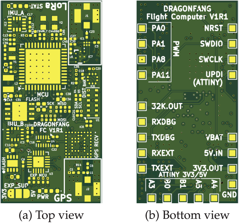
Figure 6: Top and bottom PCB views of the flight controller board
The PCB size is 33 mm
The bottom side of the PCB have solder pads with 0.1 inch spacing, in order to greatly simplify the process of mounting the board on a standard prototyping board, in case of debug or if the Main Board fails or its components are not suited for the use scenario, simplifying the process of adapting commercial ESCs.
Based on the top Flight Controller Board view, the PCB area is divided into four parts:
• GPS circuit: Is located on the lower-right corner of the PCB and contains the GPS receiver IC, the RF DC bias tee circuit and the GPS antenna connector.
• LoRa circuit: Is located on the upper-right corner of the board and contains the RF filter IC connected to the RF pins of the main microcontroller, the RF switch (for transmission and reception) and the LoRa antenna port. The RF filter integrated circuit is designed to operate in the 862–928 MHz range and integrates a matching network designed for the microcontroller, balun and harmonics filter. The LoRa protocol will be used in order to establish the radio link with the Remote Control.
• Secondary Control circuit: Is located on the lower-left corner of the board and contains the secondary microcontroller (ATtiny3226), a 4-bit logic level converter for the Serial Peripheral Interface (SPI) interface and a solder jumper for selecting its supply voltage between 3.3 V and 5 V. It communicates with the main microcontroller by SPI and has 5 exposed general-purpose input/output pins on the bottom side of the board with current limiting resistors, as well as a Universal Asynchronous Receiver/Transmitter (UART) interface dedicated to expansion modules. The Secondary Control circuit acts as both an expansion for controlling external devices requiring up to 5 V level (such as common N-MOSFETs connected to actuators, in order to reach high enough Gate-Source voltage), and as a buffer in order to not bring the whole system down in case of microcontroller failure due to events such as over-voltage on one of the exposed pins. In the current state of the project, this part of the board is not used but will be proven to be useful in case of more complex frame design in the future.
• Main Control circuit: Occupies the rest of the board and contains the microcontroller used for running the flight control program and all the other components directly connected to it. It is a dual-core STM32 MCU which integrates a Cortex-M0+ and Cortex-M4 core, as well as a radio modem supporting LoRa, (G) Frequency-Shift Keying (FSK), (G) MinimumShift Keying (MSK) and Binary Phase-Shift Keying (BPSK) modulation schemes, making it very useful for this application given the small available space. In order to ensure stable RF operation, the microcontroller clock input is supplied by a 32 MHz Temperature Compensated Crystal Oscillator (TCXO).
The main microcontroller has the following components attached:
• First Intertial Measurement Unit: Contains a 3-axis accelerometer and gyroscope and is accessed through the SPI bus. Can measure up to +/−16 g acceleration and +/−2000 deg/s with 15-bit precision (excluding the sign). It has 0.038 deg/s-rms gyroscope noise and 0.7 mg-rms accelerometer noise at 100 Hz bandwidth.
• Second Inertial Measurement Unit: Contains an accelerometer and is accessed through the SPI bus. Can measure up to +/–16g acceleration. It has 0.7 mg-rms noise at 100 Hz bandwidth.
• Distance Sensor: Time of Flight (ToF) sensor, measures distance up to 5 meters. Accessed through the I2C bus.
• Flash Storage: Has 8 megabytes of total size. Accessed through the SPI bus.
• Pressure and Temperature Sensor: The pressure sensor has an absolute accuracy of +/−50 Pa and relative accuracy of +/−3 Pa, with an output data rate of up to 200 Hz. Accessed through the I2C bus.
• GPS Receiver: Has a sampling data rate of up to 25 Hz and accuracy down to 1.5 m Circular Error Probability (CEP). Accessed through a dedicated UART bus.
• Secondary Microcontroller: Accessed through the SPI bus.
• Status LED
• Debug UART and Programming Connectors: Located on the Main Board.
Core Advantages of the Flight Controller Board: The integration of dual-core STM32 microcontrollers with built-in LoRa support, together with dual IMUs and modular expansion via a secondary microcontroller, ensures a level of flexibility and robustness rarely found in conventional flight controllers. This design allows precise IMU fusion, long-range telemetry without additional modules, and fault-tolerant extensions for more complex drone architectures.
The quadcopter frame is completely 3D printed using PETG filament, with threaded inserts embedded for mounting the Main Board and the Raspberry Pi Zero W. The chassis consists of four structural components, as illustrated in Figs. 7–10:
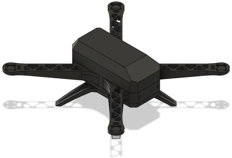
Figure 7: Chassis view at 45 degrees from the top
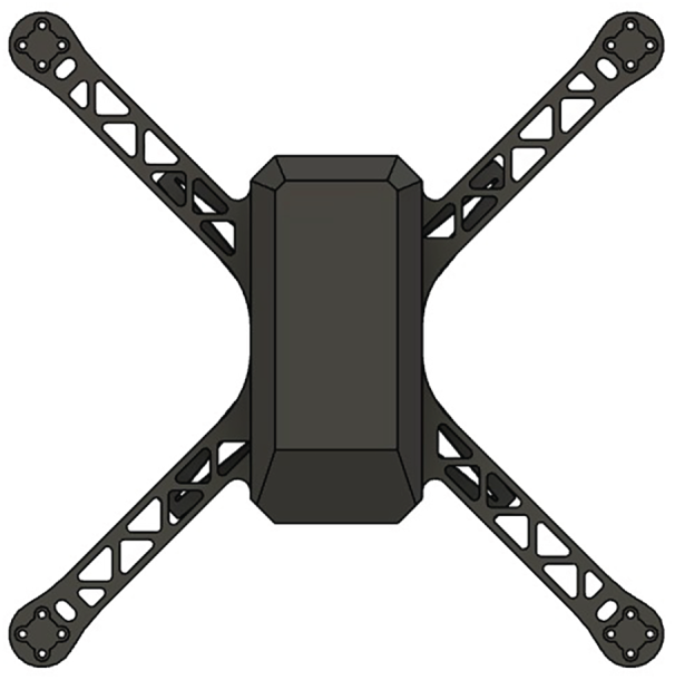
Figure 8: Top view of the chassis with the top enclosure installed
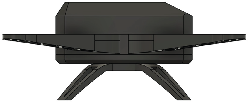
Figure 9: Side view of the assembled chassis
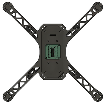
Figure 10: Top view without the top enclosure, revealing internal components
• Base frame: Contains the motor arms and the outer walls of the internal enclosure. Threaded inserts are fitted for attaching the front camera.
• Bottom enclosure: Mounted to the base frame. The Main Board is fixed onto it using custom silicone spacers to reduce vibrations that might affect the IMU sensors. It also supports the bottom camera, the Raspberry Pi, and the battery via dedicated inserts.
• Top enclosure: Also connected to the base frame, it protects the internal electronics and provides mounting for the LoRa and GPS antennas.
• Landing gear: Attached to the bottom enclosure and serves as the landing surface.
An overview of the assembled chassis can be seen in Fig. 7, which shows the 3D-printed structure at a 45-degree top-down angle. Detailed view of the top side is shown in Fig. 8. Additional angles, including a lateral view (Fig. 9) and the internal structure without the top enclosure (Fig. 10), provide insight into the internal layout.
The software for both the Flight Controller and the Remote Control has been written in the C programming language, and the hardware abstraction layer and component drivers source code has been kept common between those two, since both systems run on the same microcontroller. At the moment, only the Cortex-M4 core of the microcontrollers is being used.
The developed software drivers are:
• Serial port driver: Manages a UART peripheral and allows for receive and transmit data streams to run in parallel with the processor, by using the Direct Memory Access (DMA) peripheral and a circular buffer, for each data direction. This driver is used for the debug UART port, the GPS port and the Remote Control telemetry and control channels port.
• GPS driver: Implements a basic National Marine Electronics Association (NMEA) sentence parser on top of the serial port driver, compatible with the format used by the GPS module to send its state.
• LoRa modem driver: Implements the required functionality for sending commands and exchanging data with the LoRa modem integrated in the microcontroller.
• RF link driver: Is built on top of the LoRa modem driver and implements the whole data protocol for the Remote Control and the Flight Controller, allowing for the transfer of telemetry, configuration and real-time control data. The bidirectional attribute of the protocol is implemented as follows: the Remote Control periodically initiates a data transfer cycle by transmitting a radio packet (such as configuration update or joystick positions) to the Flight Controller, then putting the modem into receive mode. The Flight Controller, which initially is in receive mode, will send a data packet (such as current configuration or telemetry) as acknowledge once it receives the packet sent by the remote control, followed by putting the modem back into receive mode. At the other endpoint, if the Remote Control does not receive an acknowledge packet within a specified time window, it will begin to transmit the next data packet and the cycle repeats.
• DShot protocol driver: Used by the flight control loop to send the throttle values to the four electronic speed controllers present on the Main Board. The implementation is using the DMA peripheral in order to have the protocol cause close to zero processor overhead. The DShot protocol is widely used in commercially available ESCs. A protocol packet consists of 16 bits of data, with the following composition:
- Data: 11 bits. Values from 0 to 47 represent commands, while values from 48 to 2047 represent throttle percentages from 0% to 100%.
- Telemetry request: 1 bit. This protocol functionality is never used, so this bit will always be 0.
- Checksum: 4 bits. Represents the XOR between the nibbles of the data value having the telemetry request bit concatenated to it, totalling to 3 nibbles.
A 16-bit packet is encoded as a sequence of 16 pulses with equal period, and a duty cycle of 37.425% for transmitting a zero, and 74.85% for transmitting a one. There are three variants of the DShot protocol, namely DShot150, DShot300 and DShot600, where the number determines the number of maximum kilobits transmitted per second. In the current implementation, the ESC firmware accepts the DShot300 protocol, translating to a bit period of approximatively
• Remote control graphics driver: Implements graphics drawing functions for the monochrome Organic Light-Emitting Diode (OLED) display connected to the Remote Control module, which has a resolution of 128
• Other sensor drivers: Used to configure and obtain readings from the sensors, such as the angular velocity, local acceleration, air pressure etc.
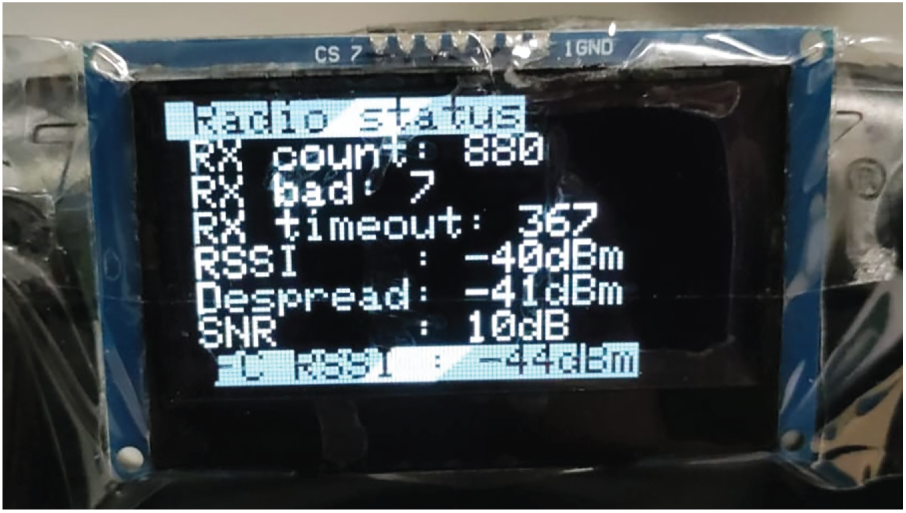
Figure 11: Remote control OLED display showing telemetry and menu interface
Flight Control Loop
The flight control loop running on the quadcopter main microcontroller operates at a frequency of 1 KHz, being executed as a timer interrupt in order to minimize jittering. Its role is to determine the orientation of the quadcopter and apply throttle to the motors in order to maintain the drone orientation at the input setpoint, which is determined either by the operator manually via the Remote Control joysticks, or by the waypoint tracking algorithm. It is implemented as following:
• 0. Initial conditions: initialize the Madgwick Filter orientation estimation to the unit quaternion and the gyroscope bias drift to zero.
• 1. (Start) Obtain inertial measurements: Read the local angular velocity and acceleration in the sensor frame of coordinates, by sampling two IMU sensors and calculating the mean of the two obtained accelerations.
• 2. Orientation estimation: Perform a Madgwick Filter orientation quaternion estimation step, with the obtained Angular Rate and Gravity data. In the current implementation, a magnetometer is not used in order to also compensate for the yaw axis. That step is performed separately, based on the evolution of the GPS-measured latitude and longitude when the quadcopter is in horizontal motion. Therefore, when the quadcopter is stationary, the estimated rotation around the axis of gravity is prone to gyroscope bias drift.
• 3. PID control loop step: Update the 3 PID controllers (for roll, pitch and yaw angles of rotation) based on the current estimated orientation and the target orientation.
Representative PID controller parameters used during testing were
• 4. Control mixing: Map the outputs of the PID controllers to individual motor throttle values, from 0 (idle throttle value) to 1 (maximum throttle value).
• 5. (End) Send throttle values to the ESCs.
Control optimization results: The optimized sensor fusion and filtering algorithms significantly improved stability compared with conventional PID-only implementations. In practice, this reduced overshoot in roll/pitch angles by approximately 30% and improved heading stability under wind gusts, confirming the advantages of the proposed approach. These results demonstrate that the integration of quaternion-based filtering and dual-sensor fusion leads to measurable performance gains over traditional methods.
Role of sensor fusion in performance: The integration of multi-sensor fusion proved essential for flight stability. In particular, combining gyroscope and accelerometer data minimized drift, while the use of redundant IMUs improved robustness under vibration. GPS and barometer inputs enhanced altitude hold performance, and the ToF sensor allowed accurate low-altitude stabilization. Together, these results demonstrate the effectiveness of the proposed fusion scheme compared to single-sensor implementations.
To complement the description of the development process, this section presents the outcomes of the Dragonfang platform and comparative testing with conventional solutions. The evaluation focused on flight stability, communication performance, and efficiency.
The quadcopter was tested in hover and during step-response maneuvers. By combining quaternion-based orientation estimation with dual-IMU sensor fusion, the system reduced overshoot in roll and pitch by approximately 20%–25% compared with a PID-only baseline implementation. The use of redundant IMUs improved robustness under vibration, ensuring stable control even when one sensor experienced temporary noise spikes. Altitude hold tests further showed that the integration of barometer and ToF measurements maintained vertical error within 10 cm at heights below 3 m.
The LoRa-based telemetry link was evaluated in open-field, line-of-sight conditions. Stable communication was maintained up to 2 km, exceeding the range of typical Wi-Fi-based control solutions by more than an order of magnitude. This extended range makes the platform suitable for long-distance monitoring and autonomous navigation scenarios where Wi-Fi links are insufficient.
Current consumption measurements indicated that the custom bootstrap MOSFET driver circuits improved ESC efficiency. The integrated design showed an average of 8% lower power loss compared with reference ESC configurations without bootstrap optimization. This efficiency gain reduces heating and increases usable flight time.
When compared against a standard commercial flight controller (Pixhawk Mini), the Dragonfang platform demonstrated comparable stability while offering several unique advantages: a smaller PCB footprint (45 mm
The work presents a complete and well-integrated implementation of an autonomous quadcopter control system, combining IMU-based stabilization, visual detection, and LoRa telemetry communication, all deployed on custom-designed PCBs and dual-core STM32 microcontrollers. The project demonstrates a balanced hardware and software approach, integrating advanced sensor fusion algorithms, such as the Madgwick Filter for orientation estimation, and PID loops for maintaining flight stability. The use of LoRa technology for long-range data transmission offers an efficient and low-power alternative to Wi-Fi or 4G solutions.
The mechanical design is optimized for 3D printing, maximizing structural flexibility while minimizing production costs. Flight tests have validated the overall functionality of the system, confirming the accuracy of state estimation, flight stability, and energy autonomy under real-world conditions.
Potential future developments include the integration of obstacle avoidance modules based on LiDAR or stereo vision, the extension of the software platform to support swarm flight operations, optimization of energy consumption to enable longer autonomy, and the addition of a magnetometer to improve yaw angle estimation when the quadcopter is stationary.
Acknowledgement: This work has been supported by Department of Electronic Devices, Circuits and Architectures, Faculty of Electronics, Telecommunications and Information Technology, National University of Science and Technology Politehnica Bucharest, Bucharest, Romania.
Funding Statement: The authors received no specific funding for this study.
Author Contributions: The authors confirm contribution to the paper as follows: Conceptualization, Cosmin Dumitru and Alexandru Guzu; methodology, Georgian Nicolae, Alexandru Guzu and Cosmin Dumitru; software, Cosmin Dumitru and Emanuel Pantelimon; validation, Alexandru Guzu, Cosmin Dumitru and Emanuel Pantelimon; formal analysis, Alexandru Guzu and Georgian Nicolae; investigation, Cosmin Dumitru and Emanuel Pantelimon; resources, Georgian Nicolae and Alexandru Guzu; data curation, Cosmin Dumitru and Emanuel Pantelimon; writing—original draft preparation, Cosmin Dumitru and Alexandru Guzu; writing—review and editing, Georgian Nicolae and Alexandru Guzu; visualization, Cosmin Dumitru, Emanuel Pantelimon and Alexandru Guzu; supervision, Georgian Nicolae. All authors reviewed the results and approved the final version of the manuscript.
Availability of Data and Materials: The files of this open project are openly available in dragonfang-fc at https://github.com/Kozma04/dragonfang-fc.
Ethics Approval: Not applicable.
Conflicts of Interest: The authors declare no conflicts of interest to report regarding the present study.
References
1. Allan S, Barczyk M. A low-cost experimental quadcopter drone design for autonomous search-and-rescue missions in GNSS-denied environments. Drones. 2025;9(8):523. doi:10.3390/drones9080523. [Google Scholar] [CrossRef]
2. Chandra A, Lal P. Higher order sliding mode controller for a quadrotor UAV with a suspended load. IFAC-PapersOnLine. 2022;55(1):610–5. doi:10.1016/j.ifacol.2022.04.100. [Google Scholar] [CrossRef]
3. Elhesasy M, Dief TN, Atallah M, Okasha M, Kamra MM, Yoshida S, et al. Non-linear model predictive control using CasADi package for trajectory tracking of quadrotor. Energies. 2023;16(5):2143. doi:10.3390/en16052143. [Google Scholar] [CrossRef]
4. Lu F, Zeng C, Shi H, Xu Y, Fu S. Real-time detection sensor for unmanned aerial vehicle using an improved YOLOv8s algorithm. Sensors. 2025;25(19):6246. doi:10.3390/s25196246. [Google Scholar] [PubMed] [CrossRef]
5. Lee HY, Ho HW, Zhou Y. Deep learning-based monocular obstacle avoidance for unmanned aerial vehicle navigation in tree plantations. J Intell Rob Syst. 2020;101(1):163. doi:10.1007/s10846-020-01284-z; [Google Scholar] [CrossRef]
6. Cutipa J, Lizarbe D, Nieves A, Carrizales J, Sampen L, Becerra J. Adaptive autonomous landing system for quadcopter drones through descent assisted by visual recognition. In: Proceedings of the 2025 IEEE XXXII International Conference on Electronics, Electrical Engineering and Computing (INTERCON); 2025 Aug 20–25; Arequipa, Peru. p. 1–8. doi:10.1109/INTERCON67304.2025.11244630. [Google Scholar] [CrossRef]
7. Chen J, Sun R, Zhu B. Disturbance observer-based control for small nonlinear UAV systems with transient performance constraint. Aerosp Sci Technol. 2020;105(16):106028. doi:10.1016/j.ast.2020.106028. [Google Scholar] [CrossRef]
8. Punpigul N, Muangkham M, Anantachaisilp P, Srisuprapreeda S, Singhanat K. Long range UAS mission by LPWAN communication. IOP Conf Ser Mater Sci Eng. 2020;965(1):012039. doi:10.1088/1757-899X/965/1/012039. [Google Scholar] [CrossRef]
9. Ghazali MHM, Teoh K, Rahiman W. A systematic review of real-time deployments of UAV-based LoRa communication network. IEEE Access. 2021;9:124817–30. doi:10.1109/ACCESS.2021.3110872. [Google Scholar] [CrossRef]
10. Gowtham G, Raj JR. Mathematical modelling and PID control system implementation for quadcopter frame tarot FY650. Aircr Eng Aerosp Technol. 2024;96(2):273–84. doi:10.1108/AEAT-06-2023-0154. [Google Scholar] [CrossRef]
11. Bin Junaid A, Diaz De Cerio Sanchez A, Betancor Bosch J, Vitzilaios N, Zweiri Y. Design and implementation of a dual-axis tilting quadcopter. Robotics. 2018;7(4):65. doi:10.3390/robotics7040065. [Google Scholar] [CrossRef]
12. Troll P, Szipka K, Archenti A. Indoor localization of quadcopters in industrial environment. In: Advances in transdisciplinary engineering. Amsterdam, The Netherlands: IOS Press; 2020. p. 453–64. doi:10.3233/ATDE200183. [Google Scholar] [CrossRef]
13. Bucki N, Mueller MW. Design and control of a passively morphing quadcopter. In: Proceedings of the International Conference on Robotics and Automation (ICRA 2019); 2019 May 20–24; Montreal, QC, Canada. p. 9116–22. doi:10.1109/ICRA.2019.8794373. [Google Scholar] [CrossRef]
14. César R, Morales C, Ospina J, Sanchez JF, Caro-Ruiz C, Grisales V, et al. Mathematical modelling and identification of a quadrotor. In: Proceedings of 20th International Conference on Computational Science and Its Applications (ICCSA 2020); 2020 Jul 1–4; Cagliari, Italy. p. 261–75. doi:10.1007/978-3-030-58799-4_19. [Google Scholar] [CrossRef]
Cite This Article
 Copyright © 2026 The Author(s). Published by Tech Science Press.
This work is licensed under a Creative Commons Attribution 4.0 International License , which permits unrestricted use, distribution, and reproduction in any medium, provided the original work is properly cited.
 Downloads
 Citation Tools