
 Submit a Paper
 Propose a Special lssue
 Open Access
ARTICLE
Simulation Analysis of the Extrusion Process for Complex Cross-Sectional Profiles of Ultra-High Strength Aluminum Alloy
1 School of Mechanical Engineering, Shanghai Jiao Tong University, Shanghai, 200240, China
2 Institute of Metal Materials Technology, AVIC Manufacturing Technology Institute, Beijing, 100024, China
* Corresponding Author: Tianxia Zou. Email:
Computers, Materials & Continua 2026, 87(1), 14 https://doi.org/10.32604/cmc.2025.074121
Received 02 October 2025; Accepted 28 November 2025; Issue published 10 February 2026
 View Full Text
 Download PDF
Abstract
Ultra-high-strength aluminum alloy profile is an ideal choice for aerospace structural materials due to its excellent specific strength and corrosion resistance. However, issues such as uneven metal flow, stress concentration, and forming defects are prone to occur during their extrusion. This study focuses on an Al-Zn-Mg-Cu ultra-high-strength aluminum alloy profile with a double-U, multi-cavity thin-walled structure. Firstly, hot compression experiments were conducted at temperatures of 350°C, 400°C, and 450°C, with strain rates of 0.01 and 1.0 s−1, to investigate the plastic deformation behavior of the material. Subsequently, a 3D coupled thermo-mechanical extrusion simulation model was established using Deform-3D to systematically analyze the influence of die structure and process parameters on metal flow velocity, effective stress/strain, and temperature distribution. The simulation revealed significant velocity differences, stress concentration, and uneven temperature distribution. Key parameters, including mesh density, extrusion ratio, die fillet, and bearing length, were optimized through full-factorial experiments. This optimization, combined with a stepped flow-guiding die design, effectively improved the metal flow pattern during extrusion. Trial production based on both the initial and optimized parameters were carried out. A comparative analysis demonstrates that the optimized scheme results in a final profile whose cross-section matches the target design closely, with complete filling of complex features and no obvious forming defects. This research provides a valuable reference for the extrusion process optimization and die design of complex-section profiles made from ultra-high-strength aluminum alloys.Keywords
The demands for materials in the aviation industry have been increasingly stringent. Due to their exceptional mechanical and chemical properties, ultra-high-strength aluminum alloys have become an ideal choice for aerospace structural materials. By optimizing alloy composition and processing techniques, the mechanical properties of aluminum alloy structures can be significantly enhanced, thereby achieving weight reduction and improved safety [1,2]. Owing to its flexible cross-sectional design, dense structure, and high material utilization rate, extrusion has become one of the primary forming processes for aviation aluminum alloy components [3,4]. Al-Zn-Mg-Cu alloy extrusions have been extensively utilized in aircraft structural components, including fuselage frames, stringers, ribs, floor beams, and seat rails [5]. However, current applications primarily focus on profiles with simple cross-sections, with the representative ones being “Z” and “T” cross-sections [6,7]. The forming of large-width thin-walled profiles with complex cross-sections remains challenging. With the continuous improvement in the strength of aluminum alloys, there is a pressing need to study the extrusion process of ultra-high-strength aluminum alloy profiles with complex cross-sections.
Aluminum alloy extrusion process is often accompanied by inherent challenges, including non-uniform metal flow, insufficient filling of the cross-section, surface cracks, and variations in microstructure and properties [8]. Particularly in the extruded profiles possessing fine features, significant flow lag could be induced in micro-feature regions due to the “size effect of structural features,” which severely limits forming completeness [9]. These defects are not only detrimental to the dimensional accuracy and surface quality of the profiles but may also lead to a substantial degradation in their mechanical performance and service stability. Systematic studies have been conducted to reveal the underlying mechanisms and optimize the process window with the aid of finite element simulation. Results showed that both die geometry [10–13] and process parameters [14–16] have great influences on metal flow stability, dimensional accuracy of the cross-section, microstructural evolution, and final properties.
In the field of die design, research has shifted from experience-dependent approaches to active optimization based on flow control. Chen et al. [17] addressed the issue of flow inhomogeneity in complex multi-cavity aluminum profiles for high-speed trains by systematically optimizing the porthole and bearing lengths using the Arbitrary Lagrangian–Eulerian (ALE) method, which significantly improved the velocity uniformity at the exit cross-section. Similarly, based on the ALE method, Liu et al. [18] improved material flow and die strength by redesigning the welding chamber and baffle plates, effectively suppressing core rod deflection during the extrusion of high-aspect-ratio profiles, and successfully produced qualified profiles validated by experiments.
Systematic regulation of process parameters is equally central to achieving high-quality extrusion forming. By combining experiments with QForm simulations on AA6063 aluminum alloy profiles featuring multi-cavity thin-walled complex sections, the influence mechanisms of temperature and speed on microstructure and mechanical properties were revealed by Wang et al. [19]. Through experimental investigation into the effects of hot extrusion parameters and aging treatment on the microstructure and mechanical properties of 2219 aluminum alloy, the optimal process parameters and associated mechanisms were identified by Wan et al. [20]. Furthermore, multi-objective optimization using the Taguchi method was applied by Prabhu et al. [21], where the dominant influences of punch angle and core rod length on extrusion load and tensile strength were quantitatively determined.
In summary, systematic methodologies have been established through advanced simulation techniques for die structure innovation and process parameter optimization, providing a solid theoretical foundation and practical guidance for the extrusion forming of conventional aluminum alloy profiles. However, significant uncertainties remain when applied to the frontier combination of “new high-strength aluminum alloy” and “complex thin-walled sections”. These materials exhibit higher deformation resistance and poorer plastic flowability at elevated temperatures. When flowing through the aforementioned complex sections, these characteristics substantially exacerbate flow path obstruction and velocity fluctuations, thereby significantly increasing the risk of defects such as insufficient sectional filling, stress concentration, and surface cracks. Therefore, it is imperative to develop an integrated methodology for extrusion forming and quality control specifically tailored to this particular material-structure system.
To address the aforementioned challenges, the present study takes the double-U multi-cavity thin-walled profile made of a novel spray-formed Al-Zn-Mg-Cu ultra-high strength aluminum alloy as the specific research object. The hot deformation behavior of this alloy is characterized through hot compression experiments. A three-dimensional thermally coupled extrusion simulation model is constructed to systematically analyze the distribution characteristics and root causes of issues related to metal flow, stress/strain fields, and temperature fields in the initial design. Finally, through a full factorial experimental design, extrusion process parameters and die structure (including mesh density, extrusion ratio, die corner radius, and bearing length) are systematically optimized. The effectiveness of the optimized solution is validated through actual trial extrusion and quantitative measurements, providing both theoretical guidance and practical references for the extrusion forming of similar difficult-to-form profiles.
2.1 Material Hot Compression Experiment
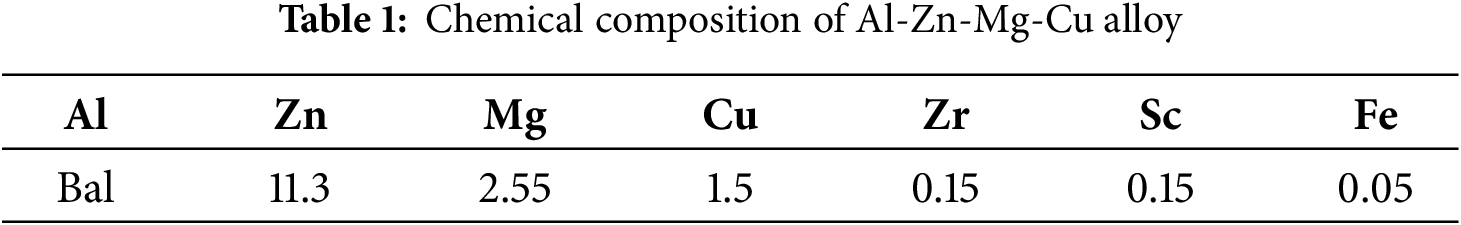
To obtain flow stress data for the highly alloyed Al-Zn-Mg-Cu ultra-high strength aluminum alloy during hot deformation, hot compression experiment was conducted. The Al-Zn-Mg-Cu billet was prepared through spray forming technology. The detailed chemical composition of the material is presented in Table 1. All tests were performed using a Gleeble-3500 thermal simulation testing system. Temperature and strain rate represent the two key process parameters that influence hot deformation behavior. Three temperature levels were selected: 350°C, 400°C, and 450°C. This selection covers the continuous temperature range from dynamic recovery at low temperatures to significant softening at high temperatures. Two strain rates were applied, 0.01 and 1.0 s−1, which represent different deformation rate conditions affecting the plastic deformation behavior of the alloy.
Cylindrical specimens were prepared and subjected to axial compression loading using the thermal simulation apparatus. During the experiment, the deformation amount started from 0 and gradually reached 1 in an incremental manner. Through this continuously changing deformation amount setting, the plastic deformation characteristics of the alloy under different deformation degrees were comprehensively captured, providing data support for the subsequent analysis of the behavior of this ultra-high-strength aluminum alloy during the extrusion process.
This study focused on an aluminum alloy profile with a cross-sectional size of 410 mm × 76 mm. The cross-sectional configuration is a typical symmetric double-U multi-cavity structure. This profile has complex geometric features, including multiple open and closed cavities, slender grooves, stepped structures, and small rotation. The local wall thickness varies significantly (from 2.8 to 5.8 mm), and the extrusion is quite difficult. The specific geometric parameters are shown in Fig. 1. Affected by its structural complexity, this profile is subject to several challenges during extrusion: firstly, the large wall-thickness gradient is likely to cause problems such as non-uniform metal flow, insufficient filling, or local over-filling, which affect the forming accuracy and stability. Secondly, the multi-cavity layout demands higher requirements for the design of the die shunt system, which needs to reasonably guide the metal flow to avoid defects caused by uneven flow velocity. Thirdly, the edge-closed and semi-closed small fillet regions pose higher requirements for flow control, die accuracy, and lubrication and cooling systems. To improve the initial flow state, reduce the risk of stress concentration, and enhance the forming quality of the profile, a 15° chamfered structure was introduced at the end of the profile. This design modification aims to optimize the metal inflow path and increase forming stability.
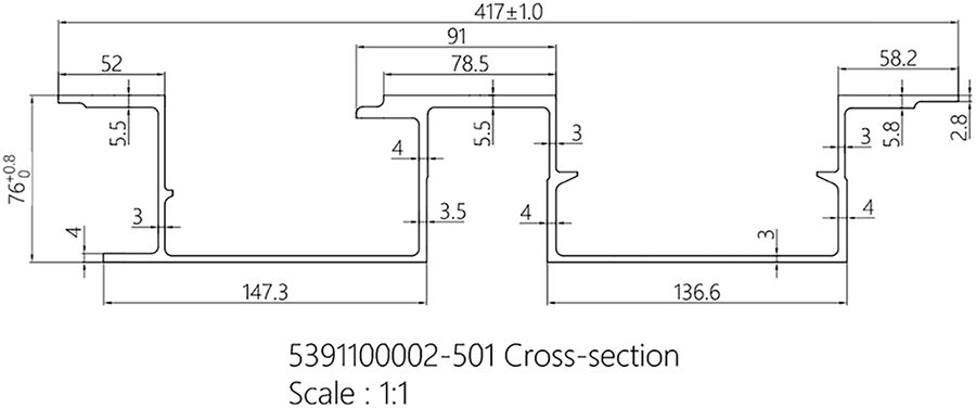
Figure 1: Cross-sectional view of the profile
Focusing on the double-U multi-cavity thin-walled aluminum alloy profile, a three-dimensional thermo-mechanical coupling extrusion simulation model was established based on Deform-3D, and the die was designed according to the optimal parameters determined by the simulation. Trial extrusion was subsequently carried out on a Taiyuan Heavy Industry 7200-t direct-acting extrusion press. Air cooling was adopted for cooling, and the direction and air volume were adjusted according to the on-site conditions.
This study investigates the extrusion process of ultra-high-strength aluminum alloy profiles with double-U multi-cavity thin-walled structures. The research commenced with the characterization of the material through hot compression experiment to elucidate its plastic deformation behavior under thermo-mechanical conditions, thereby establishing a foundational basis for subsequent investigations. A three-dimensional coupled thermo-mechanical finite element model was then developed using Deform-3D to simulate the initial extrusion scheme. The simulation results were analyzed in terms of metal flow velocity, stress-strain, temperature field, and forming defects. Subsequently, optimization schemes were designed from two aspects: process parameters and die structure. The optimal mesh density, extrusion ratio, die chamfer, and bearing length were determined through full factorial experiments, and the optimization scheme was verified through simulation. A die was then manufactured based on the optimized parameters, and actual extrusion trials were conducted using an extrusion press. The validity of the optimized approach was verified from the perspectives of metal flow uniformity and defect suppression. Finally, a comparison between simulation and experimental results was conducted, confirming the effectiveness of the optimization method for the extrusion of complex cross-sectional profiles. The overall technical roadmap is illustrated in Fig. 2.
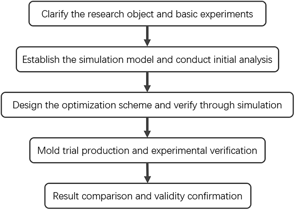
Figure 2: Technical roadmap
Focusing on the double-U multi-cavity thin-walled structure with the core objective of optimizing metal flow uniformity, a single-hole one-step extrusion die design was adopted in this study. The die structure and assembly are illustrated in Fig. 3. The overall design consists of an upper die and a lower die. The die structure dimensions are Φ470 mm × 800 mm, matching a billet size of Φ446 mm × 113 mm. High-pressure deformation is achieved through a stepped flow guide in the single-hole die cavity. Simultaneously, a 15° chamfer is applied at the bearing entry to reduce stress concentration, and a gradually tapered bearing is utilized at the die orifice edge to prevent tearing defects. These design features collectively enable effective control of the metal flow path, mitigation of stress concentration, and reduction of forming defect risks in complex cross-sections.
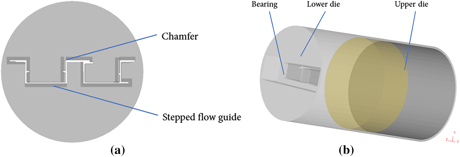
Figure 3: Cross-section and assembly drawing of the die. (a) Die cross-section and extrudate outlet profile; (b) Assembly drawing of the extrusion model
3.3 Extrusion Simulation Model
3.3.1 Deform Extrusion Simulation Model
A three-dimensional thermo-mechanical coupled extrusion simulation model was established using Deform-3D software. Billet was meshed with non-uniform grids, with element sizes ranging from 3.6 to 7.2 mm, resulting in approximately 130,000 elements in total. Regarding the thermal boundary conditions, the initial temperature of the billet was set at 350°C (below the softening threshold of 560°C to avoid excessive plastic flow of the metal at high temperatures), while the die temperature was maintained within a range of 420°C to 500°C. The die material was regarded as a rigid body. A shear friction model with a friction factor of 0.01 was applied at the contact interfaces to represent actual lubricated conditions. The loading condition was defined by a ram speed of 2 mm/s. The bearing length was set to 200 mm, and the extrusion ratio was 35.
3.3.2 Deform Extrusion Simulation Model
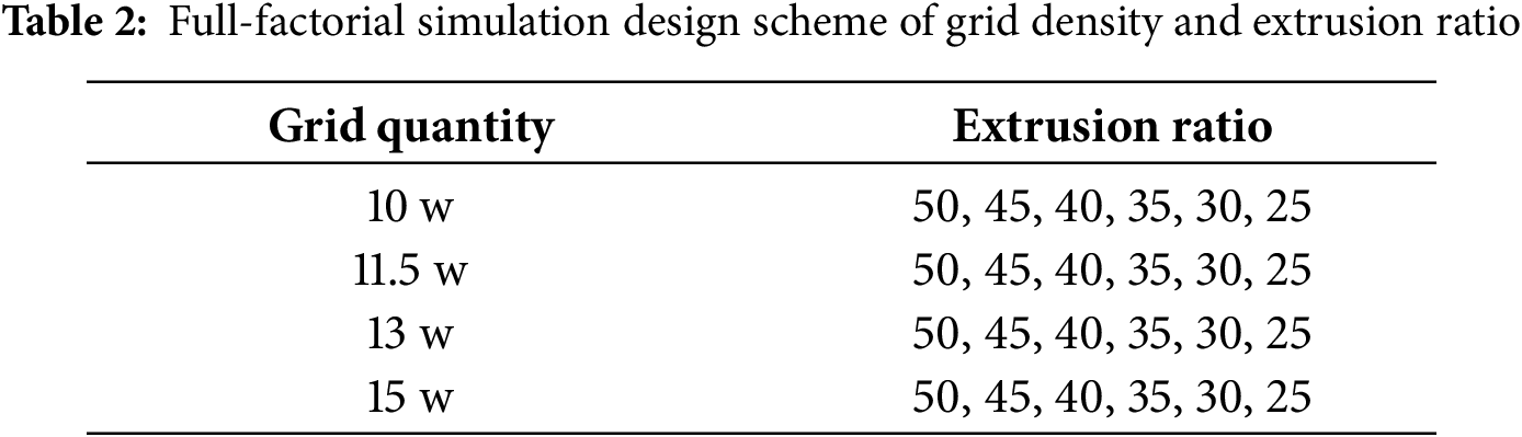
In the finite element simulation of hot extrusion, an excessively low mesh density will lead to insufficient description of complex cross-section details, affecting the accuracy of flow path and defect prediction. On the other hand, an excessively high density will increase the computational burden and easily cause convergence difficulties and remeshing errors. Meanwhile, although a large extrusion ratio can improve the material utilization rate, it will significantly increase the flow resistance and die load, easily resulting in problems such as stress concentration and flow non-uniformity. Conversely, a small extrusion ratio may reduce the forming driving force, which is not conducive to complete filling of the complex cross-sections. Based on this, this study adopted the full-factorial experimental design method to systematically construct 24 groups of simulation test schemes composed of 4 groups of mesh densities (100,000, 115,000, 130,000, 150,000) and 6 groups of extrusion ratios (50, 45, 40, 35, 30, 25). The specific test combinations and parameter configurations are shown in Table 2.
3.3.3 Research on Mold Optimization
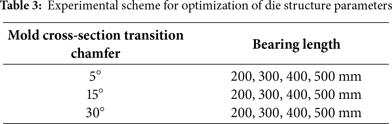
During the hot extrusion process, the die structural parameters have a significant impact on the metal flow behavior, stress distribution, and forming quality. Among them, the chamfer radius and bearing length are the key control factors. If the chamfer is too small, stress concentration and flow dead zones are likely to form in the corner area, leading to local wrinkles and die fatigue; if it is too large, the flow path will be extended, causing uneven flow velocity. If the bearing is too short, it is easy to cause unstable flow and dimensional deviation; if it is too long, the deformation resistance and die wear will be intensified. Therefore, the reasonable design of the above parameters is crucial for improving the forming stability and accuracy. To systematically investigate the influence of these two factors on extrusion behavior, a full-factorial numerical experimental design was implemented in this study. A combined analysis was carried out across different chamfer angles (5°, 15°, 30°) and bearing lengths (200, 300, 400, 500 mm), resulting in a total of 12 simulation cases. The specific test combinations and parameter configurations are shown in Table 3.
4.1 Results of Hot Compression Experiments
Experimental results revealed that the stress-strain behavior of the spray-formed Al-Zn-Mg-Cu ultra-high strength aluminum alloy varied significantly with strain rate and temperature during hot compression testing, as presented in Fig. 4.
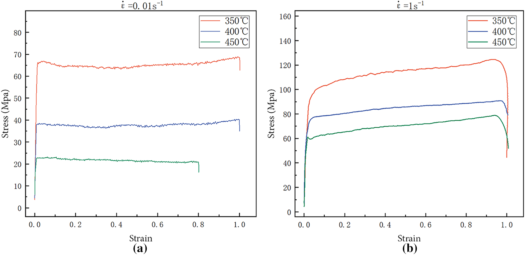
Figure 4: Thermal compression stress-strain curve. (a)
At a strain rate of 0.01 s−1, similar characteristics were exhibited in the stress-strain curves of the alloy at different temperatures. Specifically, the stress was observed to increase rapidly until a strain of approximately 0.1 was reached, followed by entry into a relatively stable stage until the strain approached 1.0, where a slight decrease occurred. The peak stresses corresponding to the three temperatures were recorded as 68.87 MPa (350°C), 40.36 MPa (400°C), and 23.18 MPa (450°C). This behavior indicates that dynamic recovery serves as the dominant softening mechanism under low strain rate conditions, resulting in the maintenance of stable flow stress throughout most of the deformation process.
At a strain rate of 1 s−1, significantly different stress behavior was observed. The stress showed a sharp initial increase, followed by continuous growth throughout the deformation process. A rapid decrease only occurred as the strain approached 1.0. The recorded peak stresses were 124.58 MPa at 350°C, 90.82 MPa at 400°C, and 78.86 MPa at 450°C. This continuous rising trend indicates pronounced work hardening effects. The behavior demonstrates that at high strain rates, the dislocation multiplication rate exceeds the dynamic softening rate, resulting in continuous flow stress enhancement.
Both strain rate and temperature have significant influences on the hot deformation behavior of the alloy. At low strain rates, the deformation process is dominated by dynamic recovery, resulting in lower and relatively stable flow stress. Under high strain rates, work hardening becomes predominant, leading to significantly elevated flow stress levels. These findings provide an important basis for optimizing hot working parameters of this novel alloy. Furthermore, they supply critical rheological stress data for subsequent numerical simulations.
4.2 Analysis of the Initial Scheme Results
4.2.1 Analysis of Extrusion Flow Velocity of Aluminum Alloy Profiles
Under specific extrusion conditions, the finite element simulation results showed that flow velocity was significantly uneven flow velocity phenomenon on the end-face of the die exit of the aluminum alloy profile during the stable extrusion stage. As shown in Fig. 5, in the cross-section, the metal flow velocity in Area A with thinner wall thickness or geometric protrusions was relatively high (10–20.5 mm/s), while that in Area B with larger wall thickness or gentle geometry was significantly lower (0–7 mm/s), forming obvious “fast-flow zones” and “slow-flow zones”. The distribution of node flow velocities in Fig. 6 further shows that the velocity distribution range is wide, with a standard deviation of 9.91 mm/s and an average value of 7.41 mm/s, indicating that flow is highly non-uniform.
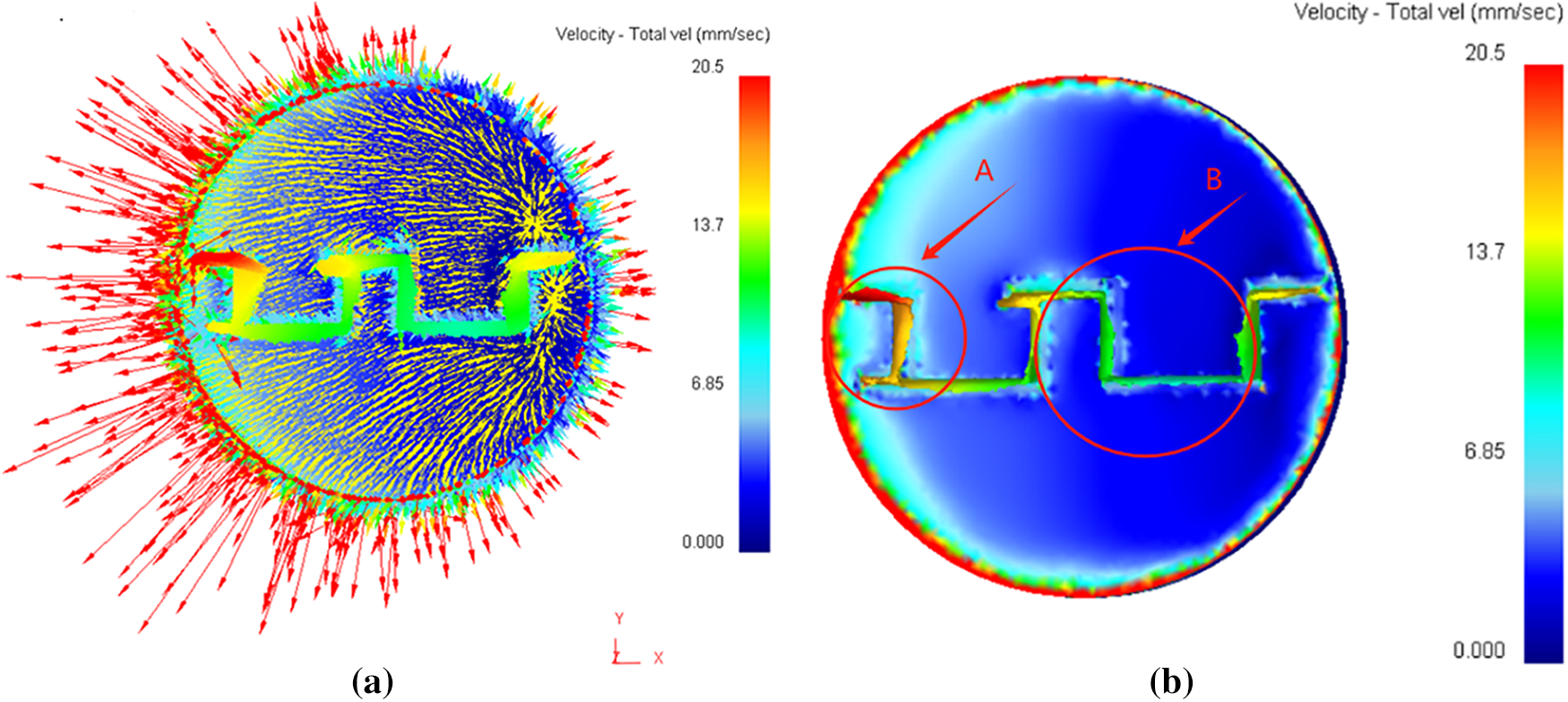
Figure 5: Flow velocity diagram of the initial extrusion stage of extruded aluminum profiles. (a) Vector diagram; (b) Contour plot
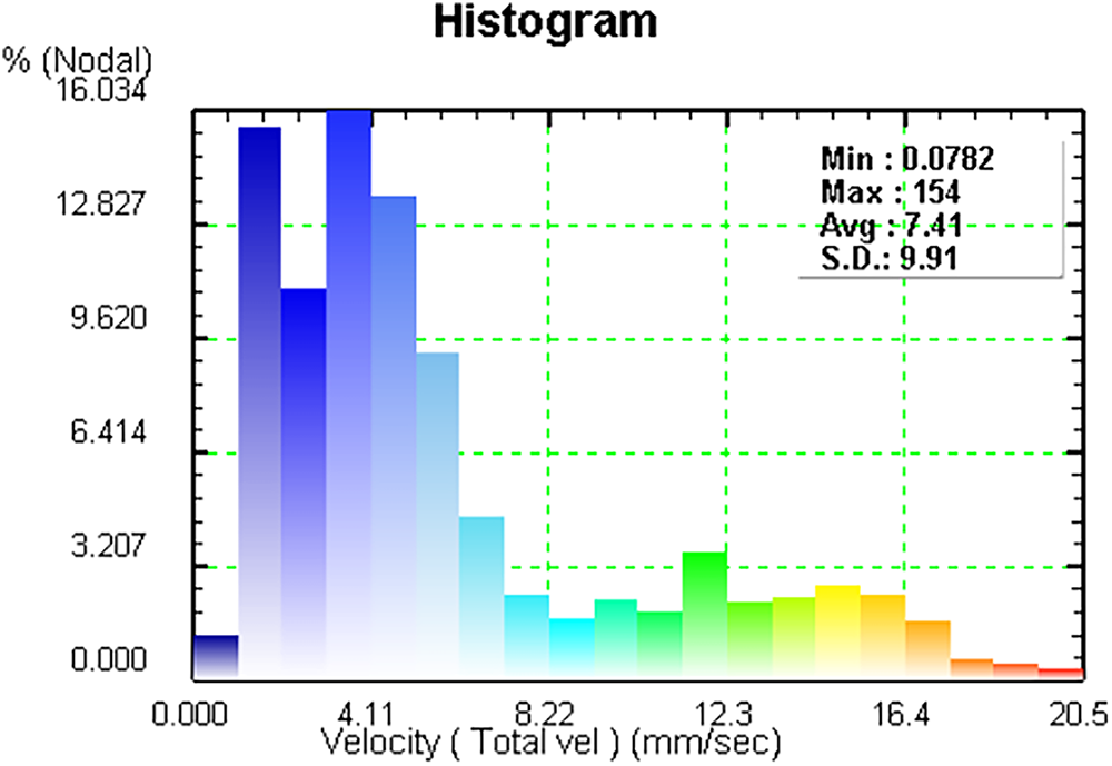
Figure 6: Flow velocity histogram
The flow velocity uniformity of low-strength aluminum alloy was selected for comparison with that of the high-strength aluminum alloy in this paper. The standard deviation (S.D.) of the flow velocity is used as the measurement index, and its expression is as follows:
where,
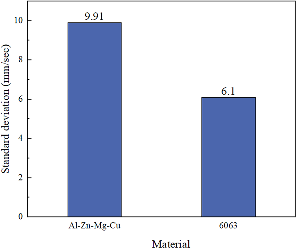
Figure 7: Comparison chart of flow velocity standard deviations of different materials
4.2.2 Analysis of Effective Stress in Extrusion
During the steady extrusion stage, the distributions of both effective stress and equivalent plastic strain on the cross-section at the die orifice exit of the aluminum profile exhibited significant spatial non-uniformity, as shown in Figs. 8 and 9. The effective stress contour plot indicates that the stress in most areas is at a relatively low level (0–400 MPa). However, stress concentration in thin-walled parts and regions of geometric discontinuity leads to a local stress of up to 809 MPa, indicating significant deformation resistance in these areas. The stress concentration mainly results from the non-uniform metal flow induced by the complex cross-sectional structure and the difficulty in local plastic deformation compatibility caused by the geometric discontinuity of the cross-section, which may lead to the generation of micro-cracks and aggravated die wear. The effective strain contour plot further reveals that although the strain distribution in the main area of the profile is relatively uniform (0–5.12 mm/mm), there are obvious high-strain areas in specific areas, such as the right-hand edge, where the local strain reaches over 10.2 mm/mm. Analysis indicates that this phenomenon is related to the relatively fast metal flow velocity in the edge area, severe local shear deformation, and geometric discontinuity. The consistency between the stress and strain fields verifies the problem of uneven local metal flow and highlights its potential impact on forming quality, microstructure uniformity, and die life.
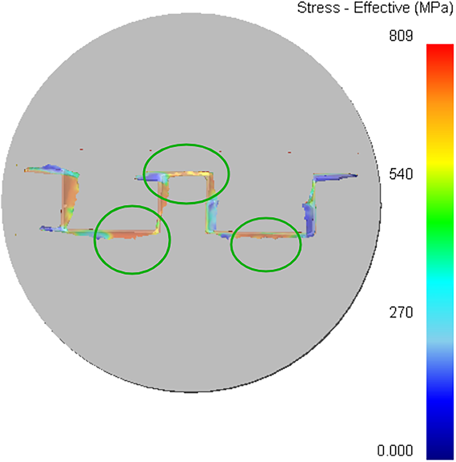
Figure 8: Effective stress contour of the profile
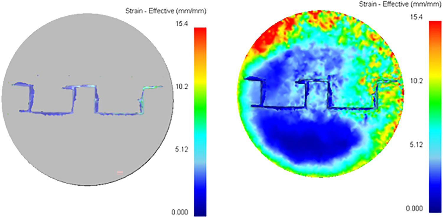
Figure 9: Effective strain contour plot of the profile
4.2.3 Analysis of Temperature Field in Extrusion Molding
Fig. 10 shows a temperature contour plot. Under the initial process conditions, there is obvious temperature non-uniformity in the profile exit cross-section: the temperature in the thick-walled area is significantly lower (about 130°C–200°C), while the temperature in the thin-walled and corner areas is higher (up to 240°C–300°C). This phenomenon is mainly caused by the coupling effect of multiple physical mechanisms: although the deformation heat per unit volume in each area is similar, the temperature rise in the thick-walled area is limited due to its large heat capacity. Additionally, the slower metal flow velocity in this area leads to a decrease in relative sliding with the die and a reduction in frictional heat generation. In addition, the slow flow velocity results in a longer contact time with the die, intensifying heat conduction loss and further suppressing the temperature rise. On the contrary, in the thin-walled area, due to the fast flow velocity, strong friction, short contact time, and severe local deformation, significant heat accumulation occurs. In summary, the non-uniformity of the cross-sectional temperature field is the result of the combined action of factors such as plastic deformation heat, frictional heat generation, heat capacity difference, and heat dissipation efficiency.
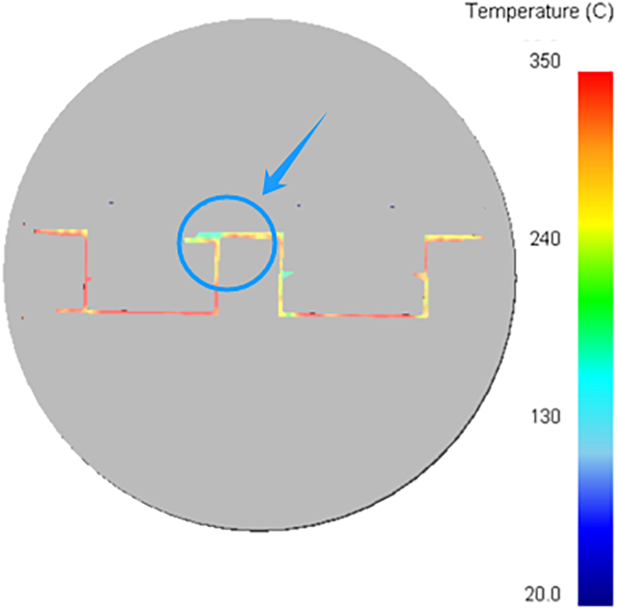
Figure 10: Distribution diagram of profile extrusion temperature
4.2.4 Analysis of Extrusion Effect
Fig. 11 shows the evolution of equivalent stress in the aluminum alloy during the whole process from the start of compression to stable extrusion under the initial process conditions. In the initial stage (Step −1), the billet is in a stress-free state. As the deformation progresses (Step 30, 60, 100), the stress is gradually established and expands inward. The high-stress regions are concentrated at the die shoulder and the area where the metal first enters the die hole. After entering the stable extrusion stage (Step 304), although the profile contour has basically taken shape, the internal stress distribution is still uneven. The residual stress in local areas is significantly high, especially at the die contact area and the geometric mutation area (marked by the red circle in Fig. 12), where obvious forming defects appear, manifested as local discontinuity, indentation or tearing signs of the material, accompanied by extremely high local effective stress. The root causes of the above-mentioned phenomena are as follows: on the one hand, non-uniform metal flow leads to excessive local tension or shear, which easily forms defects in the confluence area or the area with restricted flow; on the other hand, the differences in deformation paths and constraint conditions caused by the complex cross-section geometry induce incongruent deformation; at the same time, if the stress concentration at the geometric mutation area exceeds the bearing limit of the material in the thermal state, it will directly trigger the initiation and propagation of micro-cracks.
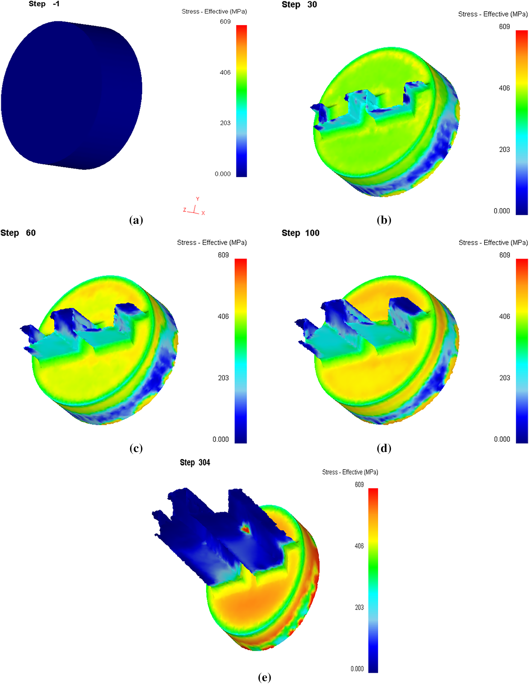
Figure 11: Extrusion result. (a) Step −1; (b) Step 30; (c) Step 60; (d) Step 100; (e) Step 304
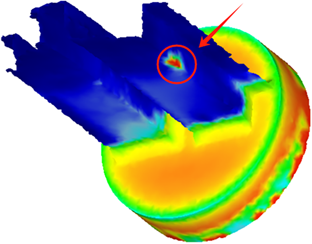
Figure 12: Defects of extruded profiles
4.3 Optimization of Extrusion Parameters and Dies
4.3.1 Determination of the Optimal Extrusion Process Parameters and Die Structure
Based on the results of the aforementioned full-factorial simulation tests, a comprehensive analysis was conducted on key factors influencing the quality of extrusion. In terms of mesh discretization, the initial simulation employing 100,000 elements revealed difficulties in achieving convergence within certain forming channels due to excessively large element sizes. Frequent remeshing resulted in local element deficiency, which affected the simulation stability and calculation accuracy. By gradually increasing the number of elements to 115,000, 130,000, and 150,000, it was found that the model with 130,000 elements exhibited improved compatibility between element size and geometric features, along with enhanced contact algorithm stability. This configuration also significantly reduced volume loss while maintaining manageable computational resource requirements. Consequently, the mesh density of 130,000 elements was ultimately identified as optimal.
Regarding the optimization of the extrusion ratio, simulation results indicate that although a higher extrusion ratio (e.g., 45, 50) promotes the degree of plastic deformation in the metal, thereby improving the microstructural densification and mechanical properties, it also induces more violent metal flow. This leads to significant stress concentration within the die, elevating the risk of fatigue failure, along with potential defects such as non-uniform flow velocity and metal delamination. When the extrusion ratio is reduced to 35, the load distribution on the die becomes more uniform, and metal flow homogeneity improves markedly. Consequently, the defect occurrence rate decreases significantly, synchronously optimizing extrusion efficiency and forming quality. When the extrusion ratio is reduced to 30, although lowering the die load and deformation resistance, due to an insufficient degree of plastic deformation of the metal, it is difficult to effectively break the original as-cast structure, which easily leads to coarse grains and inadequate densification, thus affecting the mechanical properties of the material. Therefore, an extrusion ratio of 35 is identified as optimal for achieving comprehensive performance.
Among die structural parameters, the entrance chamfer is a critical feature for controlling metal flow. This study specifically addresses the transitional chamfer designed at the bearing entrance to avoid sharp corners. Simulation results indicate that a small 5° chamfer causes a relatively abrupt change in metal flow direction. Significant local stress concentration is observed in areas with sudden thickness changes. The stress level in this configuration is higher than in the 15° design, indicating greater risks of surface tearing and die fatigue. A large 30° chamfer provides an excessively gradual transition. Although flow resistance is reduced, the metal flow path is prolonged. This shows limited improvement in filling coordination for certain narrow cavities in complex sections. Substantial increases in machining difficulty and manufacturing cost are also recorded. The 15° chamfer is proven to achieve the optimal balance between flow guidance and manufacturing economy. This angle effectively guides the smooth directional transition of the metal flow and sufficiently reduces stress concentration at geometric transitions. Structural interference and machining burden are also avoided. Therefore, the 15° chamfer is selected as the optimal solution, with its die cross-section shown in Fig. 13.
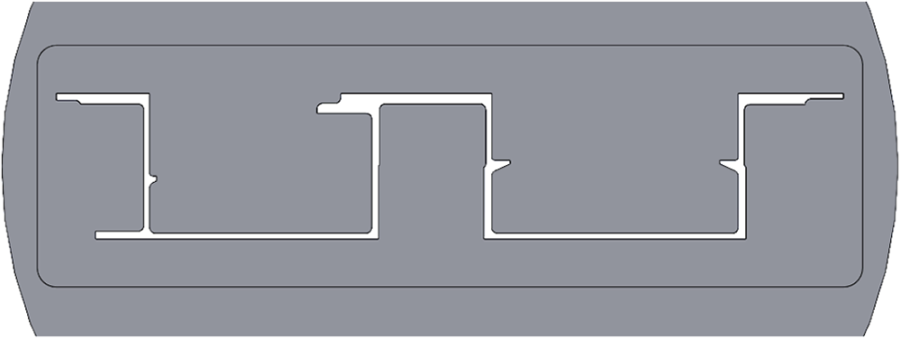
Figure 13: Cross-sectional view of the optimized die
In terms of the bearing length, a shorter length of 200 mm leads to increased dimensional fluctuations and surface defects. Although a length of 500 mm improves the flow, it significantly increases the friction and extrusion force, accompanied by a risk of die sticking. Comparative results indicated that a bearing length of 400 mm achieved the best balance in controlling extrusion force, enhancing flow stability, and suppressing defect formation, and was therefore identified as the recommended value.
In summary, through the full-factorial simulation experiment, this study has optimized and determined the following optimal set of extrusion process and die design parameters: a mesh density of 130,000 elements, an extrusion ratio of 35, a die transition angle of 15°, and a bearing length of 400 mm.
4.3.2 Simulation Verification and Result Analysis of the Optimal Scheme
During the extrusion simulation process, the flow velocity distribution became increasingly non-uniform as the simulation progressed, as shown in Fig. 14. By Step 800, a non-uniform flow trend appeared at the top of the extrusion cross-section; to Step 900, this non-uniform phenomenon had intensified; and at Step 1277, the cross-sectional flow velocity was unstable, and this state had deviated from actual working conditions. Considering simulation accuracy and physical credibility, the research focused on the results before Step 800.
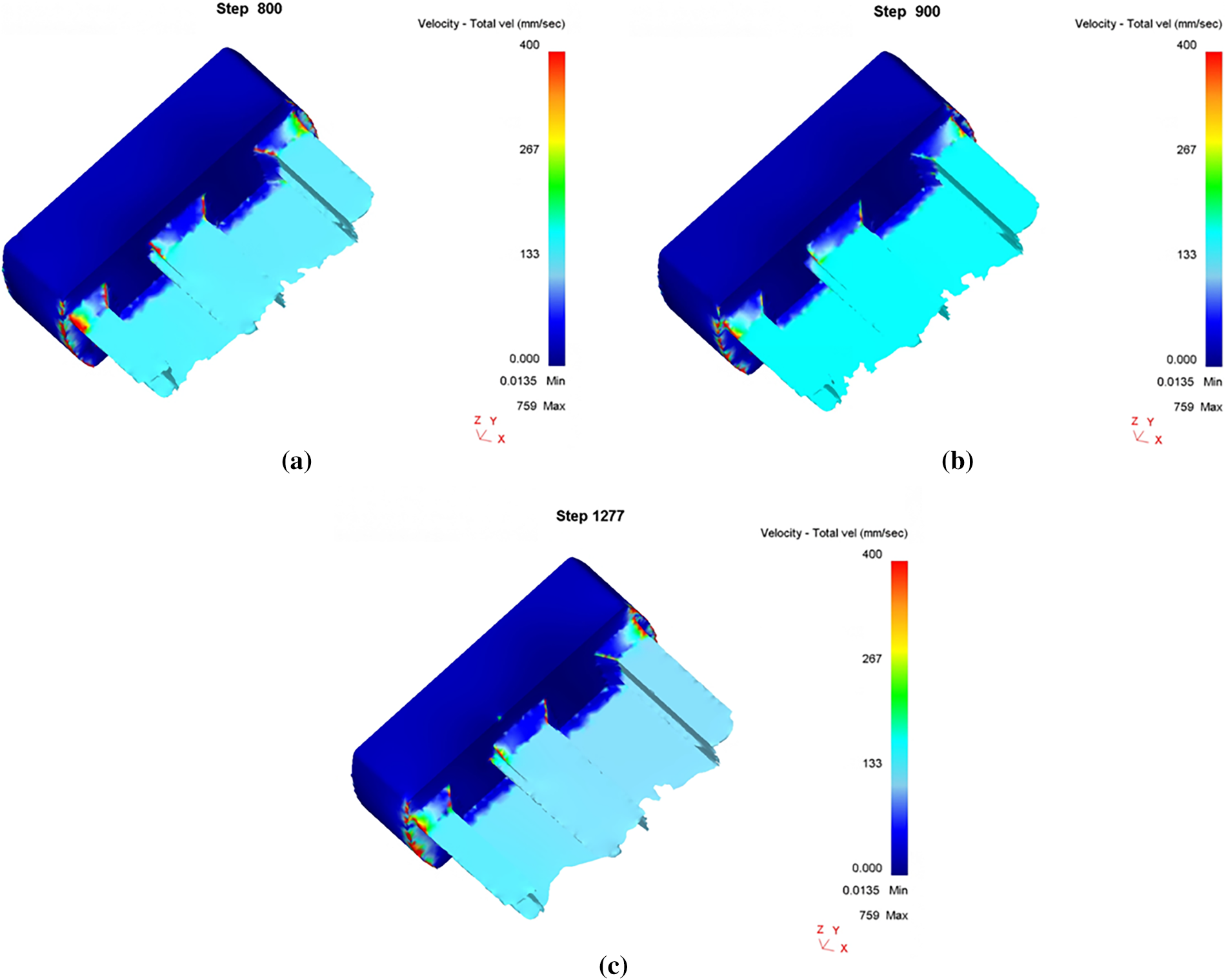
Figure 14: Simulation results after 800 steps. (a) Step 800; (b) Step 900; (c) Step 1277
Within this valid analysis interval, the optimized die structure and process parameters significantly improved the uniformity of the metal flow velocity. The flow distribution at the die orifice exit became more homogeneous, and the gradient decreased significantly. As shown in Fig. 15, the high-velocity differential of 13.5 mm/s across the previously profile section has been substantially reduced. The main flow velocities were concentrated in the range of 16.7–33.3 mm/s (green to yellow-green range), and the previously prominent “fast-flow zone” and “slow-flow zone” phenomena have been effectively alleviated. The statistical results of the node flow velocities showed that most of the node flow velocities are concentrated in the range of 10–25 mm/s, and the range of 15–20 mm/s has the highest proportion, reaching 18.19%, as shown in Fig. 16. Compared with the situation before optimization, where the original flow velocity distribution was broad and fluctuated severely (with a standard deviation of 9.91 mm/s and an average flow velocity of 7.41 mm/s), the flow velocity fluctuation after optimization was significantly weakened, which verified the effectiveness of the die optimization scheme.
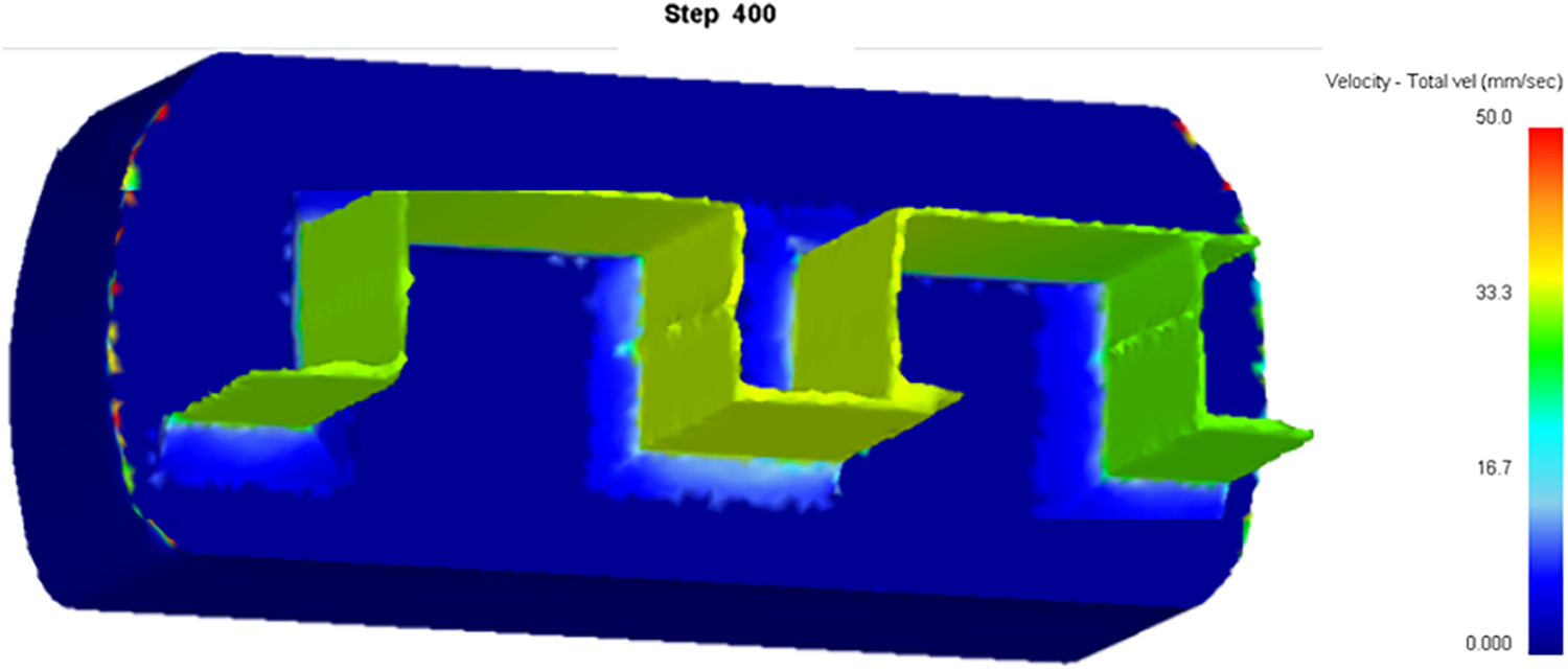
Figure 15: Flow velocity diagram of the initial extrusion stage of extruded aluminum profiles
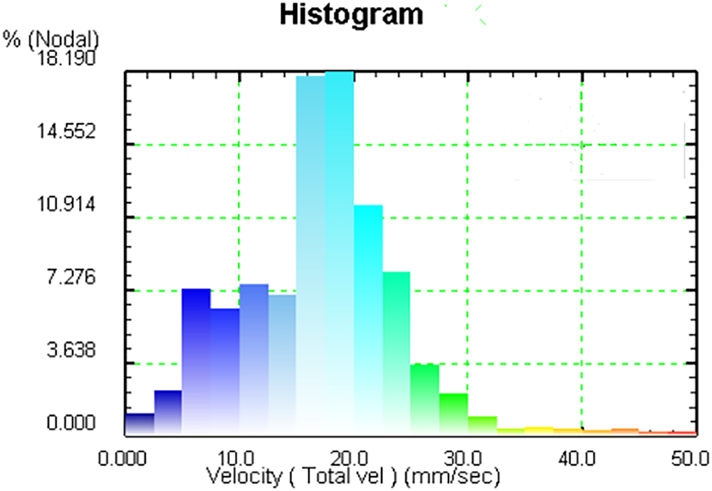
Figure 16: Histogram of the extrusion flow velocity of each part in the final forming process
By optimizing the die structure and process parameters, the metal flow state during the extrusion of high-strength aluminum alloy double-U profiles was significantly improved: the abnormal local flow velocity was effectively suppressed, and both the uniformity and concentration of the flow velocity distribution was enhanced (as shown in Fig. 17), reducing the risk of defects such as profile bending, twisting, uneven wall thickness, and microstructural and property instability.
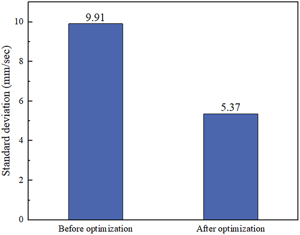
Figure 17: Comparison chart of flow velocity standard deviation before and after optimization
To quantitatively validate the extrusion accuracy of the optimized approach, a systematic geometric comparison was performed among the simulation cross-section at the stable extrusion stage (Step 800), the actual extruded profile cross-section, and the theoretical design cross-section (shown in Fig. 1). As illustrated in Fig. 18, close agreement was observed between the simulated and actual profile contours. Specifically, high consistency was achieved between the measured values and simulation predictions in key geometric features such as the outer contour, wall thickness distribution, rib positions, and internal cavity dimensions. All deviations were maintained within acceptable limits, which fully verified the accuracy of the simulation model and the reliability of the optimized process parameters.
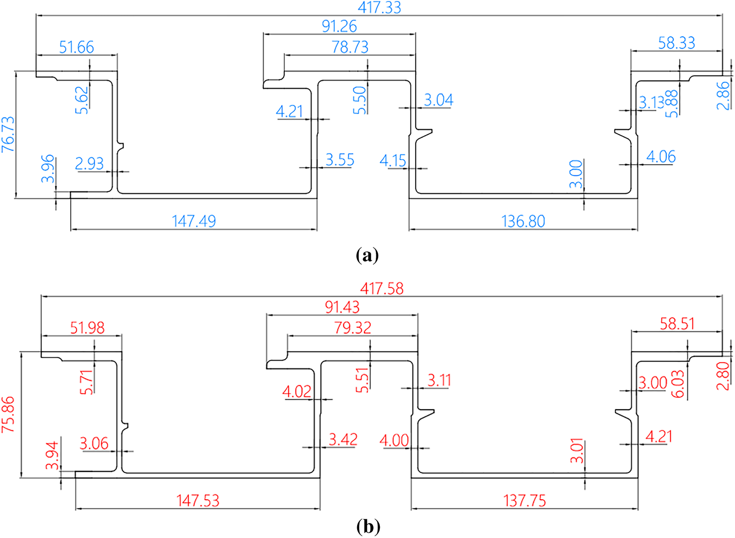
Figure 18: Comparison between simulated, experimental, and target cross-sectional profiles after optimization. (a) Simulated cross-sectional dimensions; (b) Experimental cross-sectional dimensions
In terms of cross-sectional filling completeness, both simulation and experimental results indicated sufficient material filling in all regions. Transition arcs and fine internal cavities were clearly formed without defects such as shrinkage or underfilling. It was demonstrated that the optimized die structure and process parameters effectively coordinated metal flow, leading to significant improvement in the forming quality of complex cross-sectional configurations.
Trial production was carried out using a 7200-t forward double-acting extruder from Taiyuan Heavy Industry. The effectiveness of the optimization scheme was validated from multiple dimensions. In terms of metal flow, the optimized die structure resulted in a more rational metal distribution. Fig. 19 shows the die used for trial production. A comparison of the profiles produced before and after optimization (Fig. 20) demonstrated that the actual extruded profile after optimization had a clear cross-sectional contour. Compared to the pre-optimization profile, complex features such as small corners and slender grooves were completely formed without defects like shrinkage or underfilling. Regarding dimensional accuracy, the key geometric parameters of the actual profile matched closely with those of the simulation model, and the cross-sectional contour fitted the target design. In terms of defect control, no issues such as cracks or wrinkles occurred, and the stress concentration phenomenon was effectively alleviated.
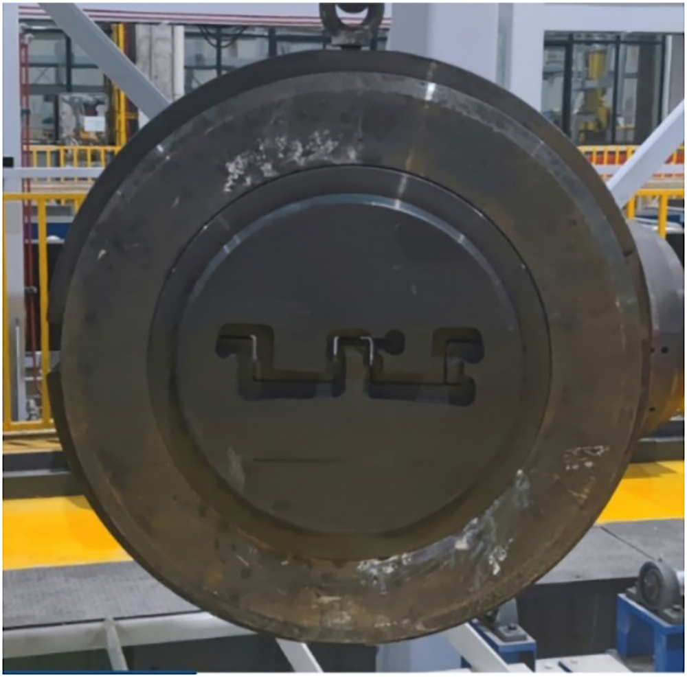
Figure 19: Physical diagram of the trial-manufactured die
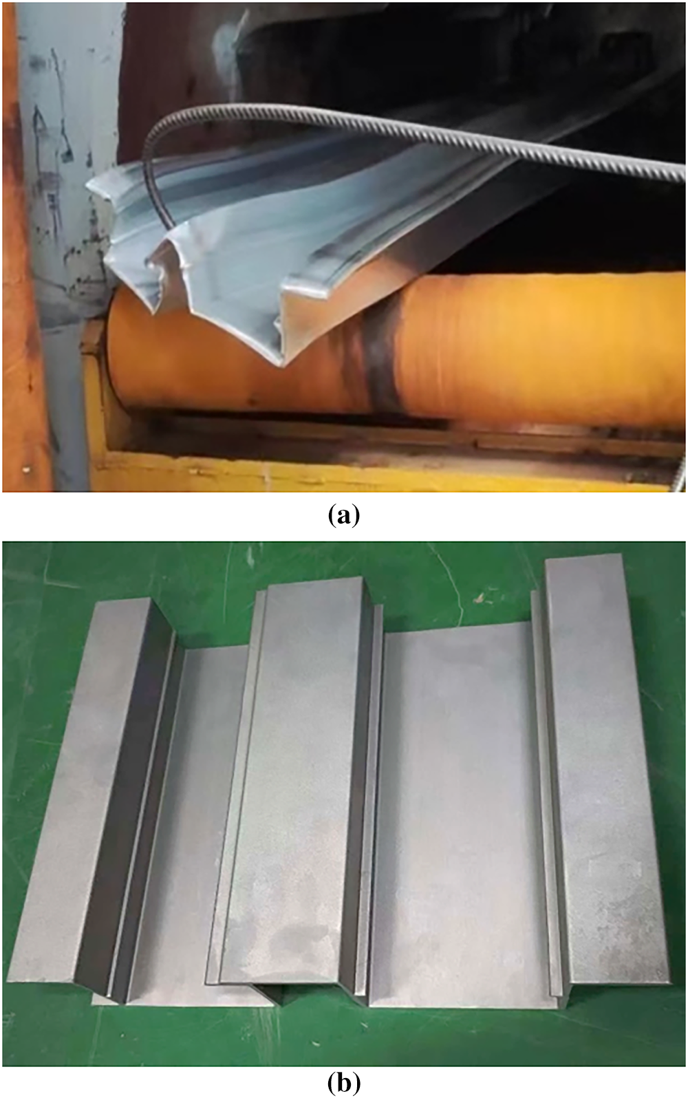
Figure 20: Comparison diagram of the physical objects of trial-produced profiles before and after optimization. (a) Physical picture of the trial-produced profile before optimization; (b) Physical picture of the trial-produced profile after optimization
Employing an integrated approach of hot compression testing, numerical simulation, and experimental trials, this study provides a comprehensive investigation into the extrusion forming challenges of spray-formed Al-Zn-Mg-Cu ultra-high strength aluminum alloy double-U multi-cavity thin-walled profiles. The main conclusions are as follows:
(1) Hot compression experiment demonstrate that the flow stress of this novel alloy significantly decreases within the 350°C–450°C temperature range, indicating the dominant role of thermally activated softening. More importantly, the prevailing deformation mechanism transitions with strain rate. At a low strain rate of 0.01 s−1, the flow stress remains relatively low and stable, a behavior dominated by dynamic recovery. In contrast, at a high strain rate of 1 s−1, continuous flow stress increase is observed, demonstrating the dominance of work hardening. This finding clearly reveals the intrinsic reason for the high susceptibility to metal flow instability during extrusion, which is attributed to the uneven distribution of strain rates in the deformation zone.
(2) Full factorial simulation results based on Deform-3D indicate that mesh density must balance accuracy and computational efficiency: excessively large element sizes lead to contact non-convergence and volume loss, while excessively dense meshes significantly increase computational cost. Extrusion ratio must reconcile forming stability and microstructural properties; excessively high ratios intensify flow resistance, stress concentration, and energy consumption, whereas overly low ratios result in inadequate densification due to insufficient plastic deformation. In die design, the transition angle and bearing length are particularly critical: an appropriate transition angle effectively guides metal flow and mitigates stress concentration, while a suitable bearing length stabilizes flow velocity at the exit and avoids dimensional fluctuations or frictional damage.
(3) Based on the optimal parameter set, trial production demonstrated that the cross-sectional contour of the formed profile closely aligns with the target design. Complex features were completely filled, with no defects such as cracks, shrinkage voids, or twisting observed. When compared to the pre-optimization condition which exhibited contour deviation, incomplete feature formation, and surface defects, the optimized process shows substantial improvement in product quality. These results confirm both the effectiveness and the reliability of the proposed optimization scheme in engineering practice.
Acknowledgement: Not applicable.
Funding Statement: This work was supported by the National Key Research and Development Program of China (Grant No. 2023YFB3710805).
Author Contributions: The authors confirm contribution to the paper as follows: Methodology: Tianxia Zou, Yilin Sun, Fuhao Fan; Data collection: Tianxia Zou, Fuhao Fan; Simulation: Tianxia Zou, Zhen Zheng; Experiment: Tianxia Zou, Yilin Sun; Writing—original draft preparation: Tianxia Zou, Fuhao Fan, Yanjin Xu, Baoshuai Han; Writing—review and editing: Tianxia Zou, Yilin Sun, Fuhao Fan, Zhen Zheng, Yanjin Xu. All authors reviewed the results and approved the final version of the manuscript.
Availability of Data and Materials: Not applicable.
Ethics Approval: Not applicable.
Conflicts of Interest: The authors declare no conflicts of interest to report regarding the present study.
References
1. Paulisch-Rinke MC, Manzoni AM, Agudo Jácome L, Vogel F, Reimers W. Influence of chemical composition on microstructure and mechanical properties in the extruded aluminum alloys 7021B and 7175. Mater Des. 2025;258(3):114649. doi:10.1016/j.matdes.2025.114649. [Google Scholar] [CrossRef]
2. Stemper L, Tunes MA, Dumitraschkewitz P, Mendez-Martin F, Tosone R, Marchand D, et al. Giant hardening response in AlMgZn(Cu) alloys. Acta Mater. 2021;206:116617. doi:10.1016/j.actamat.2020.116617. [Google Scholar] [CrossRef]
3. Shaeri MH, Shaeri M, Salehi MT, Seyyedein SH, Djavanroodi F. Microstructure and texture evolution of Al-7075 alloy processed by equal channel angular pressing. Trans Nonferrous Met Soc China. 2015;25(5):1367–75. doi:10.1016/S1003-6326(15)63735-9. [Google Scholar] [CrossRef]
4. Fang G, Zhou J, Duszczyk J. Extrusion of 7075 aluminium alloy through double-pocket dies to manufacture a complex profile. J Mater Process Technol. 2009;209(6):3050–9. doi:10.1016/j.jmatprotec.2008.07.009. [Google Scholar] [CrossRef]
5. Zhang L, Li H, Bian T, Wu C, Gao Y, Lei C. Advances and challenges on springback control for creep age forming of aluminum alloy. Chin J Aeronaut. 2022;35(10):8–34. doi:10.1016/j.cja.2021.10.019. [Google Scholar] [CrossRef]
6. Liu Y, Zhang T, Gong H, Wu Y. Effect of cold pressing and aging on reduction and evolution of quenched residual stress for Al-Zn-Mg-Cu T-type rib. Appl Sci. 2021;11(12):5439. doi:10.3390/app11125439. [Google Scholar] [CrossRef]
7. Pan R, Shi Z, Davies CM, Li C, Kaye M, Lin J. An integrated model to predict residual stress reduction by multiple cold forging operations in extra-large AA7050 T-section panels. Proc Inst Mech Eng Part B J Eng Manuf. 2018;232(8):1319–30. doi:10.1177/0954405416673097. [Google Scholar] [CrossRef]
8. Remsak K, Boczkal S, Limanówka K, Płonka B, Żyłka K, Węgrzyn M, et al. Effects of Zn, Mg, and Cu content on the properties and microstructure of extrusion-welded Al-Zn-Mg-Cu alloys. Materials. 2023;16(19):6429. doi:10.3390/ma16196429. [Google Scholar] [PubMed] [CrossRef]
9. Liu Y, Xu J, Wang X, Shan D, Guo B. Metal flow hysteresis behavior and shape control strategy during porthole die extrusion of micro heat pipe. Chin J Aeronaut. 2023;36(7):268–81. doi:10.1016/j.cja.2023.01.009. [Google Scholar] [CrossRef]
10. Hu H, Zhang D, Pan F, Yang M. Analysis of the cracks formation on surface of extruded magnesium rod based on numerical modeling and experimental verification. Acta Metall Sin Engl Lett. 2009;22(5):353–64. doi:10.1016/S1006-7191(08)60109-X. [Google Scholar] [CrossRef]
11. Wu X, Zhao G, Luan Y, Ma X. Numerical simulation and die structure optimization of an aluminum rectangular hollow pipe extrusion process. Mater Sci Eng A. 2006;435:266–74. doi:10.1016/j.msea.2006.06.114. [Google Scholar] [CrossRef]
12. Liu P, Xie S, Cheng L. Die structure optimization for a large, multi-cavity aluminum profile using numerical simulation and experiments. Mater Des. 2012;36:152–60. doi:10.1016/j.matdes.2011.11.013. [Google Scholar] [CrossRef]
13. Oda S, Tanaka SI. Structure optimization of die for 6000-series aluminum alloy extrusion from numerical analysis, stress measurement, and microstructure observation perspective. Metall Mater Trans A. 2022;53(12):4509–18. doi:10.1007/s11661-022-06851-7. [Google Scholar] [CrossRef]
14. Zhang C, Yang G, Xiao L, Kan Z, Guo J, Li Q, et al. Effects of the extrusion parameters on microstructure, texture and room temperature mechanical properties of extruded Mg-2.49Nd-1.82Gd-0.2Zn-0.2Zr alloy. Int J Miner Metall Mater. 2025;32(1):136–46. doi:10.1007/s12613-024-2918-4. [Google Scholar] [CrossRef]
15. Zhang W, Zhang H, Wang L, Fan J, Li X, Zhu L, et al. Microstructure evolution and mechanical properties of AZ31 magnesium alloy sheets prepared by low-speed extrusion with different temperature. Crystals. 2020;10(8):644. doi:10.3390/cryst10080644. [Google Scholar] [CrossRef]
16. Cha JW, Park SH. Variations in dynamic recrystallization behavior and mechanical properties of AZ31 alloy with extrusion temperature. J Magnes Alloys. 2023;11(7):2351–65. doi:10.1016/j.jma.2022.10.003. [Google Scholar] [CrossRef]
17. Chen H, Zhao G, Zhang C, Guan Y, Liu H, Kou F. Numerical simulation of extrusion process and die structure optimization for a complex aluminum multicavity wallboard of high-speed train. Mater Manuf Process. 2011;26(12):1530–8. doi:10.1080/10426914.2011.551950. [Google Scholar] [CrossRef]
18. Liu Z, Li L, Li S, Yi J, Wang G. Simulation analysis of porthole die extrusion process and die structure modifications for an aluminum profile with high length-width ratio and small cavity. Materials. 2018;11(9):1517. doi:10.3390/ma11091517. [Google Scholar] [PubMed] [CrossRef]
19. Wang Y, Zhao G, Sun L, Wang X, Lv Z, Sun Y. Effects of billet heating temperature and extrusion speed on the microstructures and mechanical properties of the longitudinal welds in aluminum alloy profiles with complex cross-section. Vacuum. 2023;207(12):111578. doi:10.1016/j.vacuum.2022.111578. [Google Scholar] [CrossRef]
20. Wan S, Su H, Shao B, Zong Y, Shan D, Guo B. Changes in microstructure and mechanical properties of 2219 Al alloy during hot extrusion and post-extrusion aging. J Mater Res Technol. 2023;24:3453–63. doi:10.1016/j.jmrt.2023.04.010. [Google Scholar] [CrossRef]
21. Prabhu R, Ganapathy T, Venkatachalapathy VSK. Process optimisation of hot extrusion of aluminium 6061 alloy using bridge-die. Aust J Mech Eng. 2011;8(1):37–45. doi:10.1080/14484846.2011.11464593. [Google Scholar] [CrossRef]
Cite This Article
 Copyright © 2026 The Author(s). Published by Tech Science Press.
This work is licensed under a Creative Commons Attribution 4.0 International License , which permits unrestricted use, distribution, and reproduction in any medium, provided the original work is properly cited.
 Downloads
 Citation Tools