
 Submit a Paper
 Propose a Special lssue
 Open Access
ARTICLE
SSA*-PDWA: A Hierarchical Path Planning Framework with Enhanced A* Algorithm and Dynamic Window Approach for Mobile Robots
School of Mechanical Engineering, Dalian University, Dalian, 116622, China
* Corresponding Author: Lishu Qin. Email:
Computers, Materials & Continua 2026, 87(1), 86 https://doi.org/10.32604/cmc.2025.074739
Received 16 October 2025; Accepted 19 December 2025; Issue published 10 February 2026
 View Full Text
 Download PDF
Abstract
With the rapid development of intelligent navigation technology, efficient and safe path planning for mobile robots has become a core requirement. To address the challenges of complex dynamic environments, this paper proposes an intelligent path planning framework based on grid map modeling. First, an improved Safe and Smooth A* (SSA*) algorithm is employed for global path planning. By incorporating obstacle expansion and corner-point optimization, the proposed SSA* enhances the safety and smoothness of the planned path. Then, a Partitioned Dynamic Window Approach (PDWA) is integrated for local planning, which is triggered when dynamic or sudden static obstacles appear, enabling real-time obstacle avoidance and path adjustment. A unified objective function is constructed, considering path length, safety, and smoothness comprehensively. Multiple simulation experiments are conducted on typical port grid maps. The results demonstrate that the improved SSA* significantly reduces the number of expanded nodes and computation time in static environments while generating smoother and safer paths. Meanwhile, the PDWA exhibits strong real-time performance and robustness in dynamic scenarios, achieving shorter paths and lower planning times compared to other graph search algorithms. The proposed method maintains stable performance across maps of different scales and various port scenarios, verifying its practicality and potential for wider application.Keywords
With the development of intelligent manufacturing and smart logistics, mobile robots have become key equipment for performing autonomous transportation and scheduling tasks in complex operational systems [1–3]. Their core capability lies in reaching target locations rapidly, safely, and stably within complex and dynamic yard environments [4–6]. This imposes higher requirements on path planning systems in terms of global optimality, dynamic feasibility, real-time responsiveness, and safety margins.
In the field of mobile robot path planning, a common design approach is to combine a global path planner with a local obstacle avoidance module in order to balance planning quality and real-time responsiveness. The “A* + DWA hybrid scheme” proposed in this paper is a typical implementation of this concept [7–9]. The following section first discusses the characteristics of each algorithm individually, and then explains why their integration offers significant advantages in complex real-world environments.
Since its introduction, the A* algorithm has been widely adopted for its intuitive structure and ease of implementation [10–12]. In a known static environment map, A* can quickly converge and generate a path with low cost and minimal redundancy, which is why it remains the preferred choice for global path planning modules in modern path planning literature. Recent studies have continued to employ A* as a global reference path generator within hybrid planning frameworks, upon which local optimization or refinement is performed.
However, relying solely on A* or its variants as the only path generator also has several limitations: (1) Neglect of dynamic constraints. (2) Slow response to sudden obstacles. (3) Poor path smoothness. Therefore, many modern studies go beyond using A* alone, introducing local planning modules on top of the global path to enhance real-time obstacle avoidance capabilities.
The Dynamic Window Approach (DWA) is a typical local planning method [13–15]. It samples multiple candidate combinations of linear and angular velocities (v, ω) in the velocity space, simulates short-term predicted trajectories for each combination, and evaluates them using a cost function that accounts for obstacle avoidance, target proximity, and velocity preference. The combination with the lowest overall cost is then selected as the locally optimal velocity command. The primary advantage of DWA lies in its inherent consideration of dynamic constraints and its relatively low computational burden, making it well-suited for real-time execution within control cycles.
In recent years, the DWA and its variants have been widely used as local obstacle-avoidance modules in dynamic environments. Chen et al. [16] combined DWA with Model Predictive Control (MPC) to improve trajectory robustness, while Liao et al. [17] integrated an adaptive A* with an improved DWA to reduce path length, turning angles, and improve real-time performance. Dao et al. [18] proposed a hybrid MOPSO–DWA framework that optimizes global search and local obstacle avoidance, showing superior path quality and execution time in Automated Guided Vehicle (AGV) applications.
The integration of A* and DWA has become a key trend in mobile robot path planning. A* provides globally optimal reference paths, while DWA ensures local obstacle avoidance and real-time response. Zhang et al. [19] and Gu et al. [20] further enhanced this framework through improved heuristics and B-spline smoothing, achieving shorter paths and higher safety. Similarly, Park et al. [21] demonstrated that using improved A* with DWA enhances navigation stability and path smoothness. Xu and Liu [22] introduced fuzzy control into DWA for better robustness, and Lu and Da [23] combined ACO with DWA for improved path quality in dynamic environments. Dang [24] and Zhou et al. [25] refined heuristic and cost functions, further enhancing continuity and reducing path complexity.
In addition, in scenarios with higher complexity, quantum algorithms and heuristic optimization methods have also begun to be explored. For example, Li et al. [26] proposed a quantum algorithm with infeasible-solution constraints for collision-avoidance path planning, which helps improve planning speed and solution diversity; Fei et al. [27] proposed a UAV swarm trajectory planning method for urban target strike missions, which achieves efficient path allocation under multi-UAV cooperation through heuristic optimization. These studies provide new insights for global–local hybrid planning in dynamic and complex environments.
Overall, the hybrid A*–DWA framework has been extensively validated, proving its strong feasibility, robustness, and balance between global optimality and dynamic adaptability.
Although the framework of this work formally follows the common “improved A* + DWA” hybrid paradigm, its advantages do not lie in local parameter-level optimization, but rather stem from a systematic design at the mechanism level. Specifically, during the global planning stage, SSA* incorporates obstacle inflation and safety-cost modeling, embedding safety and smoothness directly into the search process. This ensures that the generated paths possess more reasonable safety margins and continuity, effectively reducing the frequency and complexity of subsequent local obstacle avoidance. Meanwhile, the partition-based PDWA triggering mechanism activates local planning only within potential conflict regions, avoiding the path oscillations and efficiency loss caused by traditional DWA frequently adjusting velocities in interference-free areas. Compared with other enhanced A*–DWA variants that improve only heuristic or cost functions, the proposed method achieves a synergistic optimization in both path-generation logic and response mechanism, demonstrating superior safety, stability, and real-time adaptability in complex dynamic environments, and thereby offering stronger engineering applicability and robustness.
The main contributions of this study are as follows:
(1) Improved Safe and Smooth A*: In the global planning stage, safety cost evaluation, redundant node elimination, and corner-point smoothing strategies are introduced to generate a high-quality reference path.
(2) Local DWA Trigger Mechanism: A dynamic triggering mechanism is designed to activate DWA-based local replanning when dynamic or unexpected obstacles are detected along segmented paths.
The structure of the remaining chapters is as follows: Section 2 introduces the environmental modeling; Section 3 presents the method framework; Section 4 shows the experimental and simulation results; and finally, Section 5 provides the conclusion and future work outlook. Fig. 1 illustrates the overall structure of the proposed mobile robot path planning scheme.
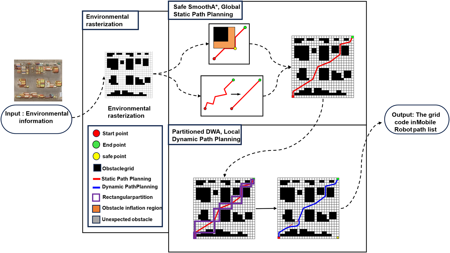
Figure 1: The overall schematic diagram of the mobile robot path planning scheme
For the path planning problem of mobile robots in complex environments, researchers have carried out extensive and systematic studies and have established relatively mature theoretical frameworks and engineering methodologies. Existing studies can generally be categorized into two main groups: those focusing on global path planning methods and those emphasizing local obstacle avoidance methods.
Global path planning is mainly based on fully or partially known environmental information to generate a globally optimal or near-optimal path from the start point to the target point. Classical graph-search algorithms such as Dijkstra and A* have been widely applied due to their completeness and heuristic optimality. Among them, the A* algorithm remains one of the most commonly used global planning methods in mobile robot path planning because of its high search efficiency and good engineering practicability. Recent survey studies indicate that A* and its improved variants are still the core technical approaches for global path searching in complex environments [28].
In recent years, to address the limitations of the A* algorithm in complex environments, researchers have proposed various improvement strategies, such as weighted heuristic functions, multi-heuristic information fusion, and safety cost modeling, in order to reduce redundant node expansions and enhance path safety and smoothness. For example, Han et al. [29] proposed an improved Theta* algorithm incorporating trajectory smoothing mechanisms to enhance path continuity; Yu et al. [30] systematically summarized various safety-aware global planning methods in recent years.
Meanwhile, a large number of studies have embedded safety margins directly into the search process by introducing risk maps and safety distance constraints. Sun et al. [31] integrated an improved A* into a multi-environment adaptive framework, improving the quality of global search in complex scenarios; Guo et al. [32] introduced adaptive weighted heuristic functions and dynamically constrained regions, significantly reducing the number of expanded nodes and enhancing path smoothness.
In addition, some works have further improved the search efficiency and path quality of traditional A* through node optimization and advanced evaluation function design [33]. Studies that integrate global–local planning concepts also indicate that the standalone adaptability of global planning in dynamic scenarios remains limited [34].
Although the above methods have improved the safety and feasibility of global paths to some extent, most of them are still developed under quasi-static environment assumptions and lack systematic safety modeling and path continuity optimization. When facing frequently occurring dynamic obstacles, traditional global planned paths often fail to simultaneously guarantee safety margins, redundant node elimination, and corner smoothing, which leads to frequent triggering of subsequent local obstacle avoidance, increased computational overhead, and degraded trajectory stability. This has become a key issue that urgently needs to be addressed in the field of global path planning.
To overcome these limitations, this paper proposes an improved SSA* algorithm. In the global planning stage, SSA* introduces redundant node elimination and corner smoothing strategies to generate high-quality reference paths. Compared with traditional methods, SSA* can significantly improve safety margins and path continuity during the planning stage, while effectively reducing the triggering frequency and computational complexity of subsequent local obstacle avoidance. Therefore, this design reflects mechanism-level innovation of this study, rather than merely parameter or weight optimization.
Local planning algorithms mainly rely on real-time perception from onboard sensors to generate feasible motion control commands within a limited time horizon. Typical methods include the Artificial Potential Field (APF), Vector Field Histogram (VFH), Timed Elastic Band (TEB), and the Dynamic Window Approach (DWA). Recent survey studies have indicated that these methods have formed a relatively mature technical system in terms of real-time performance and engineering practicality [35].
The DWA samples combinations of linear and angular velocities in the velocity space, performs short-term trajectory simulation, and evaluates candidate trajectories by comprehensively considering obstacle clearance, heading consistency with the target, and velocity constraints, finally outputting locally optimal control commands. A large number of studies have further verified the efficiency and stability of DWA in dynamic environments [36–38].
To enhance robustness, researchers have combined DWA with various intelligent control strategies. For example, Wang et al. [39] proposed a Fuzzy Dynamic Window Approach (FDWA), increasing the success rate of obstacle avoidance in complex environments; Cao and Mohamad Nor [38] designed an enhanced DWA to improve the obstacle avoidance capability of multi-robot formations in dynamic environments; Hahn [40] improved target reachability in dynamic obstacle scenarios by redefining the velocity evaluation terms of DWA. In addition, Li et al. [41] enhanced the robustness of local planners in complex dynamic environments through sliding window and kinematic constraint mechanisms.
Although the above methods have achieved significant progress in local obstacle avoidance performance, most existing studies still adopt fixed dynamic window sizes and uniform triggering mechanisms, and generally suffer from several limitations, including the lack of explicit spatially partitioned local triggering mechanisms. Therefore, how to design a partition-based, event-triggered mechanism according to environmental risk and path requirements to achieve efficient, continuous, and safe local planning has become a key issue that urgently needs to be addressed in DWA-based local path planning. The PDWA dynamic triggering mechanism proposed in this paper is specifically designed to address this problem: local planning is activated only in conflict regions, which effectively reduces redundant computation and improves obstacle avoidance reliability in dynamic environments.
In summary, although existing studies have achieved substantial progress in mobile robot path planning, several key issues still require further breakthroughs.
First, in the global planning stage, most studies still exhibit deficiencies in safety modeling and path generation. Current methods often consider safety margins only at heuristic or experience-based levels and lack systematic safety cost evaluation and redundant node optimization strategies. As a result, the generated paths in complex environments have difficulty simultaneously satisfying safety requirements and trajectory smoothness.
Second, in the local planning stage, traditional DWA and its improved variants mostly adopt uniform refresh or continuously triggered strategies and lack event-driven triggering mechanisms matched to environmental structures and conflict regions. This tends to cause unnecessary repeated computations, local oscillations, and control delays in dense or rapidly changing environments, thereby degrading planning efficiency and system stability.
To address the above limitations, this paper proposes an SSA*–PDWA framework:
(1) Safe and Smooth A* algorithm: At the global planning stage, high-quality reference paths are generated through redundant node elimination and corner smoothing strategies, enabling the paths to possess reasonable safety margins and geometric continuity during the planning stage.
(2) Segment-based dynamic triggering mechanism for DWA: Local replanning is triggered only when conflict regions or sudden obstacles are detected, thereby avoiding unnecessary repeated computation and trajectory oscillation.
Therefore, the innovation of this work does not lie merely in parameter-level improvements, but in the coordinated design of global safety modeling and local event-driven triggering mechanisms. This significantly enhances path safety, trajectory smoothness, and real-time adaptability, providing a more efficient and engineering-feasible solution for mobile robot path planning in complex dynamic environments.
Fig. 2a shows the input color remote sensing image of a port container yard with containers of different colors and shapes. To extract obstacle information for path planning, a threshold segmentation method in the Hue, Saturation, Value (HSV) color space is used. The input image
where
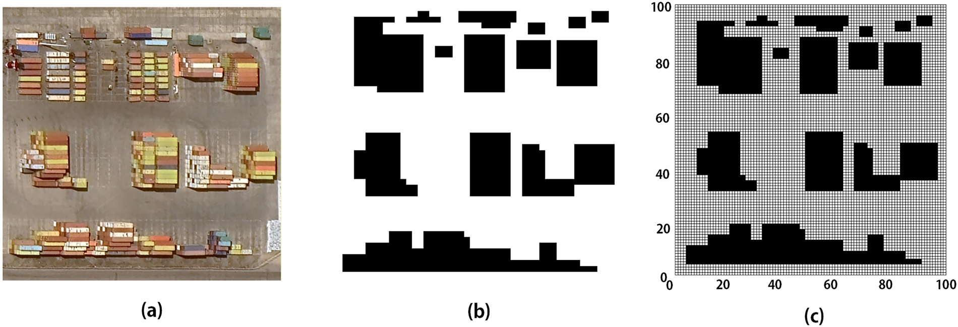
Figure 2: Simplified schematic of the port area: (a) satellite image; (b) binarized image; (c) rasterized grid map
The binary image is resized for path planning using nearest-neighbor interpolation, mapping the image to a 100 × 100 grid where each grid cell represents an occupancy value: 1 for obstacles and 0 for free space. The rescaled pixel
where
where
The resulting grid map, as shown in Fig. 2c, preserves the overall spatial distribution of obstacles while providing a discrete representation suitable for direct use in path planning algorithms.
It should be noted that the generation of the occupancy grid serves only as the basic input for the planning algorithm. In practical port applications, factors such as sensor noise, segmentation errors, shadows, specular reflections, and dynamic occlusions can indeed lead to false positives and false negatives in detecting containers, gantry cranes, pedestrians, and vehicles. To address this practical issue, this work does not attempt to fully model perception using complex sensing algorithms. Instead, an engineering-based compensation strategy is adopted: in practical deployment, manual intervention is allowed to correct the map and ensure that critical hazard areas are properly labeled; during the path planning stage, safety inflation is applied to obstacle regions to account for sensor uncertainty and increase the safety margin. Therefore, by combining “perception uncertainty compensation + planning robustness enhancement,” the proposed method effectively mitigates the impact of perception errors on path safety.
3.2 Objective Function for Path Planning
First, the Euclidean distance between any two adjacent grid cells
where
where
where a smaller
where larger angular variations correspond to sharper turns and hence higher smoothness cost, indicating reduced continuity in the robot’s motion. Based on the above considerations, the path planning problem is reformulated in a standard optimization form, including a clear objective function and explicit constraints:
subject to
where
As shown in Fig. 3, the flowchart illustrates the overall process of mobile robot path planning, integrating the SSA* global planner and the PDWA local planner. Initially, parameters are set, and the SSA* algorithm is employed to iteratively expand neighbor nodes and update the open list. Once the target node is reached, the global path is generated, and a safety-smoothing strategy is applied to enhance path quality. The path is then partitioned between turning points, with the PDWA module activated if dynamic or static obstacles are encountered. In such cases, the DWA is triggered to handle local replanning, ensuring that the optimal path is obtained. Finally, the path nodes are output, and the process ends.
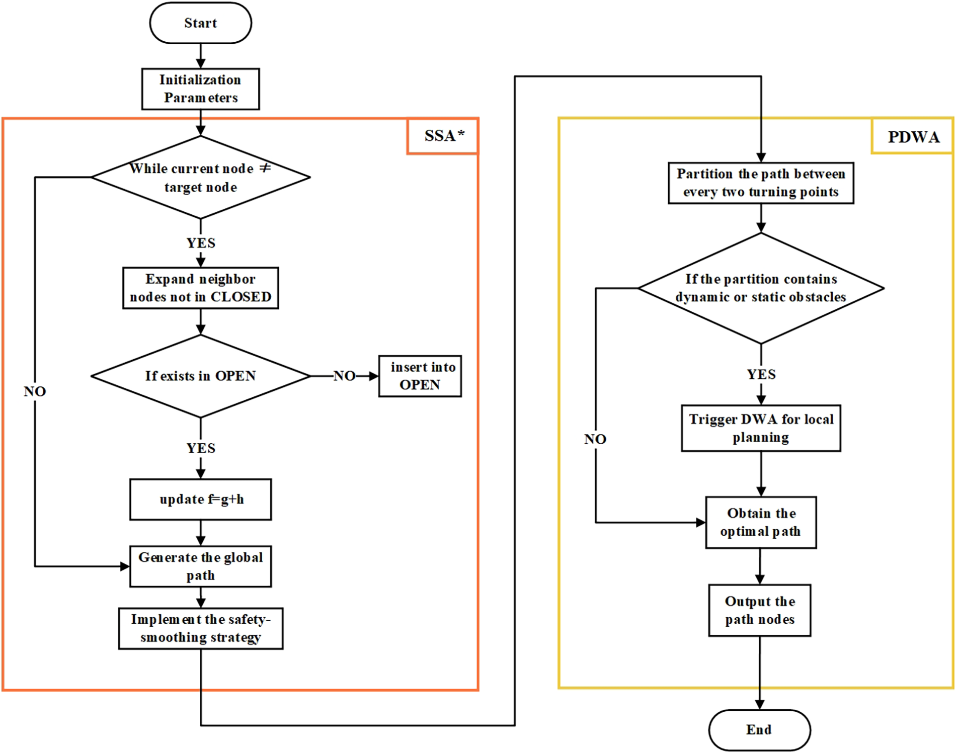
Figure 3: Flowchart of the SSA*–PDWA algorithm
4.2 Kinematic Model of the Differential Drive Robot
A differential drive robot is a commonly used mobile robot with a simple kinematic model. The robot’s motion is primarily concerned with its position, orientation, and velocity in a 2D plane. The robot’s state vector at time
where
where
In sampling-based motion planning, the velocity space
4.3 Velocity Space Constraint Analysis
To ensure the robot’s safe and controllable motion, constraints must be applied to its velocity space
First, the robot’s linear and angular velocities are limited by its hardware and motor characteristics. The feasible velocity range is defined as:
where
Second, the robot’s acceleration is limited by the motor’s performance. Since acceleration cannot change instantaneously, the variation in velocities within a time step
where
Third, in dynamic environments, the robot must avoid collisions by stopping within a safe distance. The feasible velocity set must satisfy:
where
The feasible velocity space, or Dynamic Window, is the intersection of all these constraint sets:
This dynamic window adjusts continuously based on the robot’s velocity and environmental factors. Within this window, a set of velocity samples is generated, forming candidate trajectories. An evaluation function considering goal proximity, velocity optimality, and safety is then used to select the optimal trajectory for real-time motion planning, as shown in Fig. 4.
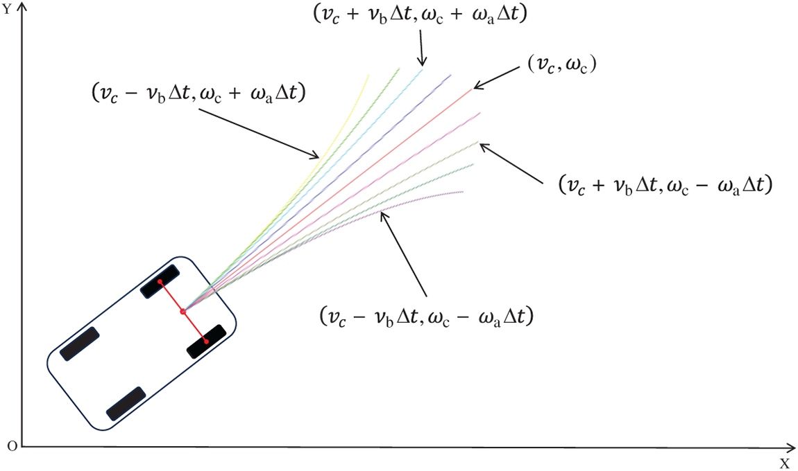
Figure 4: Schematic diagram of dynamic window sampling
After determining the robot’s feasible velocity range, candidate trajectories are generated from sampled velocity combinations. Some trajectories are feasible, while others fail due to poor obstacle avoidance or deviation from the target. A systematic evaluation is needed to select the best trajectory based on a scoring function that assesses multiple criteria. The optimal trajectory is then chosen, and its corresponding velocity command
where
where
The rationale for using candidate-set-based normalization is as follows:
(1) High adaptability: The set of feasible trajectories varies across control cycles due to changes in obstacle distribution, robot states, and sampling density. Normalization based on the current set automatically adapts to different environments.
(2) Ensures comparability: Fixed-range normalization may distort the scoring when trajectory values vary greatly between scenarios. Normalizing over the actual candidate set keeps all metrics within comparable scales.
(3) Improves robustness: This normalization prevents any metric with a large value range from dominating the total score, ensuring stability of the scoring structure.
To more appropriately determine the weight parameters α, β, and γ, this study develops a weight-setting strategy that integrates theoretical analysis with data-driven tuning. From a theoretical perspective, directional consistency ensures that the trajectory converges toward the target, avoiding unnecessary detours and local oscillations. Its importance is second only to velocity; therefore, α is assigned a medium-level weight. Since the system has already eliminated a large number of high-risk trajectories through the dynamic window filtering process, the distance term is mainly used to refine the safety margin rather than dominate the scoring stage in local obstacle avoidance planning; thus, β is set as the smallest. Maintaining sufficient forward velocity is crucial for improving navigation efficiency, reducing latency, and avoiding local oscillation behaviors; therefore, γ is set as the largest. Based on these considerations, the initial weight ranges are defined as:
Subsequently, a grid-search-based tuning method is applied in simulation environments with different obstacle densities. For each weight combination, performance indicators such as path length, travel time, and collision rate are recorded. The final optimal combination is chosen based on overall performance:
To further verify the role of each evaluation component, an ablation study is conducted by removing one term at a time. The experimental results show that:
(1) Removing the direction term leads to significant deviation from the target direction, increased path length, reduced convergence stability, and in some cases, failure to generate a valid path.
(2) Removing the distance term results in a sharp increase in collision rate, demonstrating its dominant role in ensuring safety.
(3) Removing the velocity term causes the robot to behave overly conservatively. Although safety is improved, navigation efficiency drops significantly.
In addition, sensitivity analysis of the weight parameters shows that an excessively large β results in overly cautious robot behavior, whereas an excessively small γ leads to a significant decrease in motion efficiency. This indicates that properly balancing the weight parameters is essential for achieving an optimal trade-off between safety and efficiency.
In summary, the proposed method evaluates and scores each trajectory using Eqs. (16) and (17), balancing directional accuracy, safety, and motion efficiency. The optimal trajectory, shown in Fig. 5, avoids obstacles, maintains high speed, and moves towards the goal, achieving locally optimal path planning and supporting autonomous navigation.
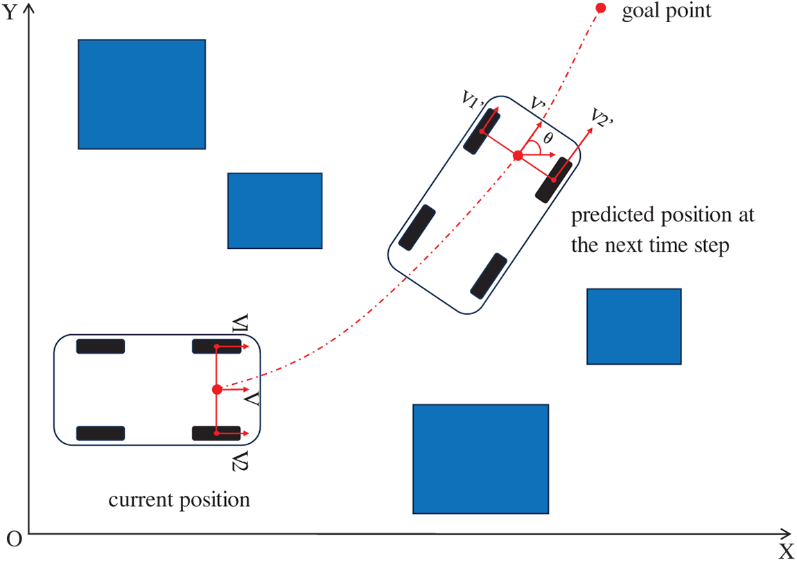
Figure 5: Schematic diagram of mobile robot operation
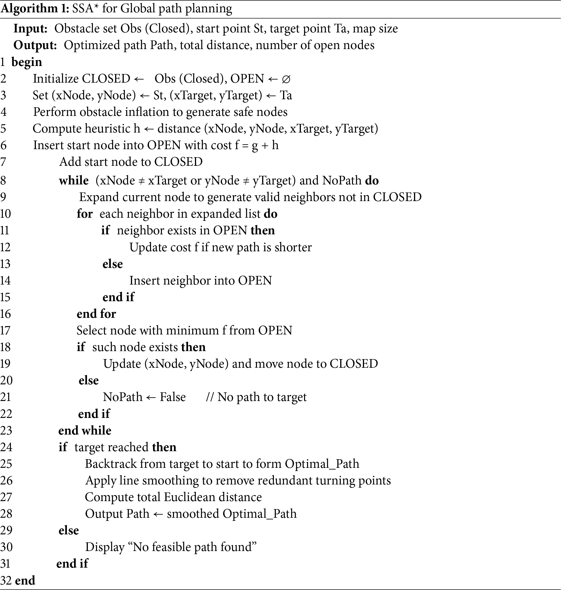
Algorithm 1 illustrates the overall process of the proposed SSA* global path planning method. Before the search phase, the algorithm introduces an Obstacle Inflation module to generate Safe Nodes around obstacles, ensuring a safe distance between the planned path and the obstacles. Subsequently, the algorithm performs environment initialization and obstacle mapping, and iteratively expands nodes based on the cost function f = g + h, dynamically removing redundant or suboptimal nodes during the search process. Once the target node is reached, the algorithm reconstructs the complete path through backtracking and refines it using a smoothing optimization procedure, thereby producing a continuous, smooth, and collision-free optimal trajectory.
To overcome the limitations of the traditional A* algorithm in practical applications, this paper proposes an improved method—the Safe and Smooth A* algorithm. On the basis of preserving the classical A* algorithm’s global optimal search capability, this approach focuses on addressing two major issues: (1) the lack of safety caused by paths being too close to obstacles, and (2) the lack of smoothness due to redundant turning points along the path.
First, during the map preprocessing stage, obstacle inflation is introduced. By expanding a certain safety margin around each obstacle, the algorithm effectively “adds safety nodes” to the search space. As a result, the generated path naturally maintains a safe distance from obstacles, significantly improving both path feasibility and execution safety, as shown in Fig. 6. In this study, to ensure simplicity and compatibility with standard grid maps, the inflation radius is set to half of a grid cell:
where
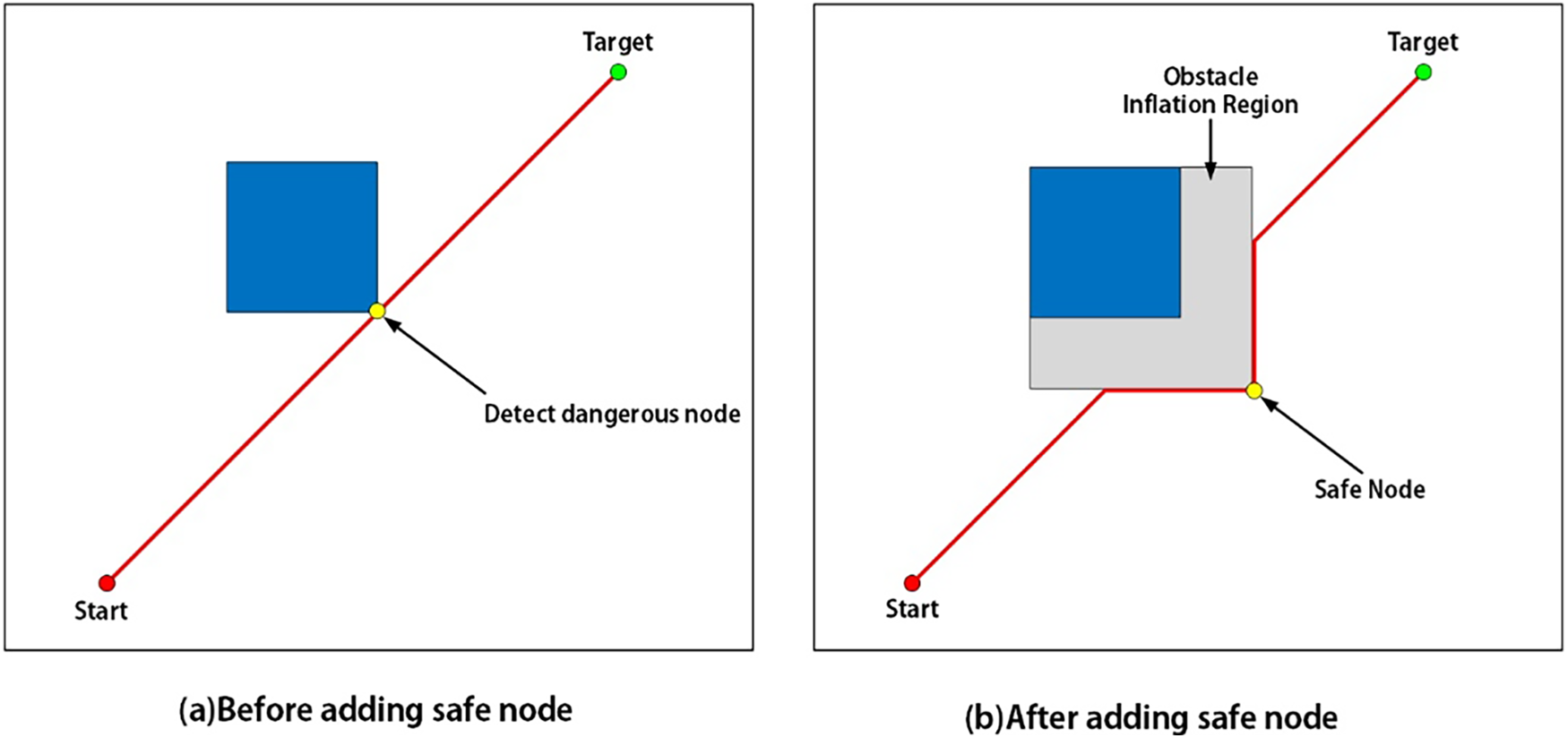
Figure 6: Schematic diagram of safe node inflation (a) Before adding safe node (b) After adding safe node
Secondly, after the initial path generation, the algorithm performs turn reduction and smoothing on the path. Specifically, it detects unnecessary corner nodes and removes them through a line-of-sight check, ensuring that the path is simplified as much as possible without colliding with obstacles. As a result, the final path not only eliminates redundant turning points and effectively shortens the total path length, but also exhibits improved smoothness and executability, as shown in Fig. 7.
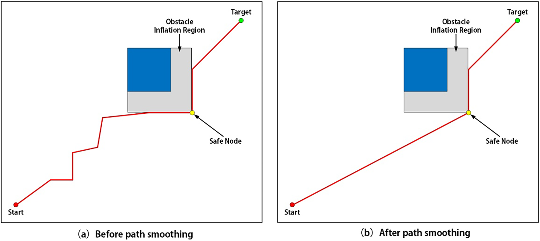
Figure 7: Schematic diagram of the smoothed path (a) Before path smoothing (b) After path smoothing
In summary, the Safe and Smooth A* algorithm achieves a dual improvement through enhanced safety and path smoothing. While maintaining its global optimality capability, it provides a safer, more concise, and highly efficient path planning solution for practical applications such as mobile robots and automated guided vehicles (AGVs).
4.6 Partitioned Dynamic Window Approach
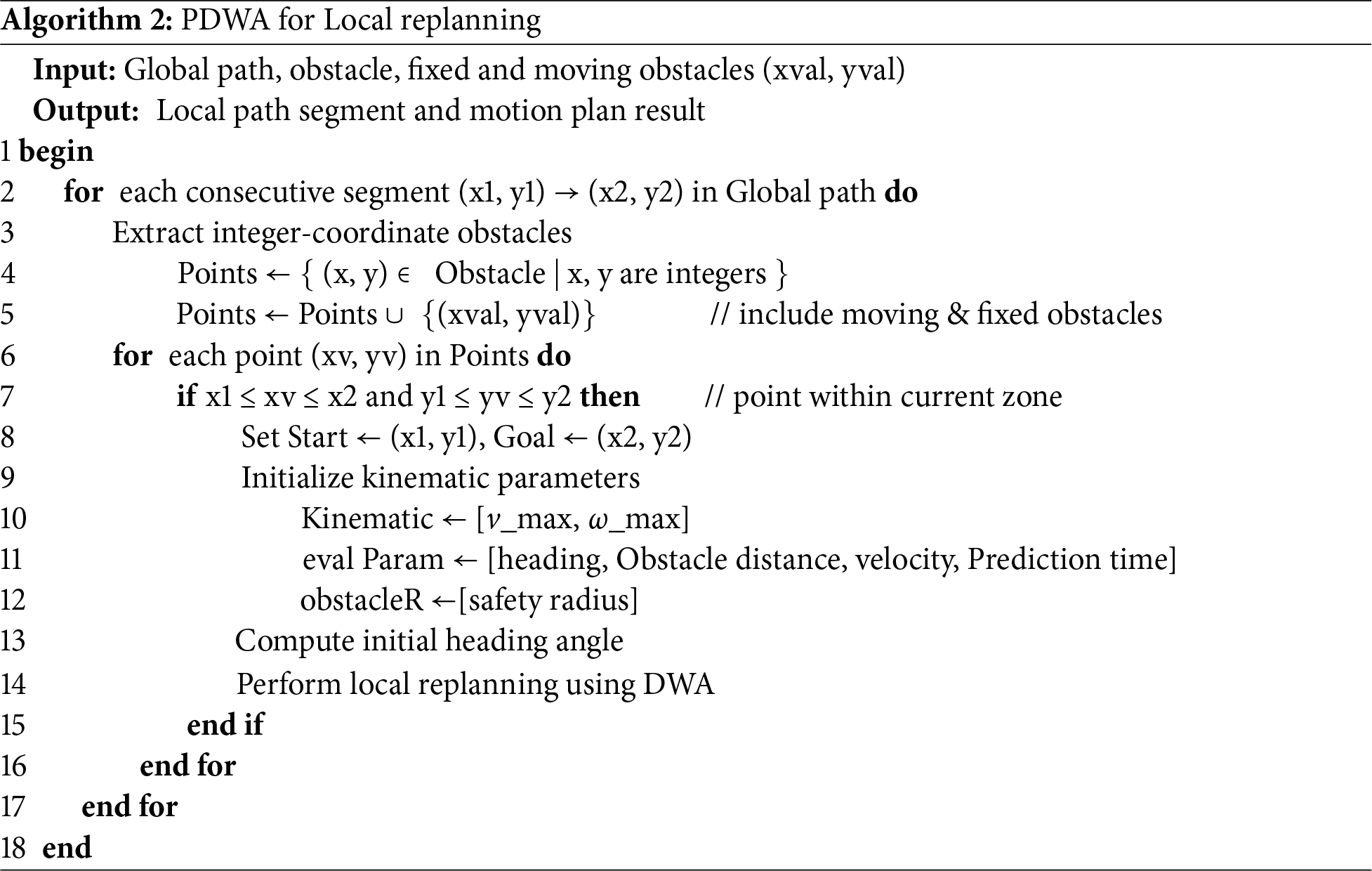
Standalone global path planning cannot handle dynamic or sudden static obstacles. To address this, the partitioned PDWA method is introduced. This approach divides the environment along the global path into consecutive local rectangular subregions (as illustrated by the purple boxes in Fig. 8), and the robot sequentially traverses these regions following the globally planned route. Algorithm 2 illustrates the process of obstacle detection and dynamic window replanning based on these partitions. The partition-based triggering strategy scans obstacles within each subregion to determine whether local replanning should be activated. When a dynamic or sudden static obstacle is detected and predicted to potentially collide with the robot within the planning time window, local DWA replanning is triggered to generate a feasible avoidance trajectory. During local planning, if no feasible velocity combination is found, the robot gradually retreats along the global path of the previous subregion while reassessing obstacle states, ensuring it does not come into contact with obstacles. To prevent deadlocks, the system sets a maximum number of replanning attempts for each subregion, and if multiple replanning attempts fail, the robot is moved to a safe location, after which the triggering conditions are re-evaluated once the dynamic obstacles have moved, ensuring that local path planning can continue.
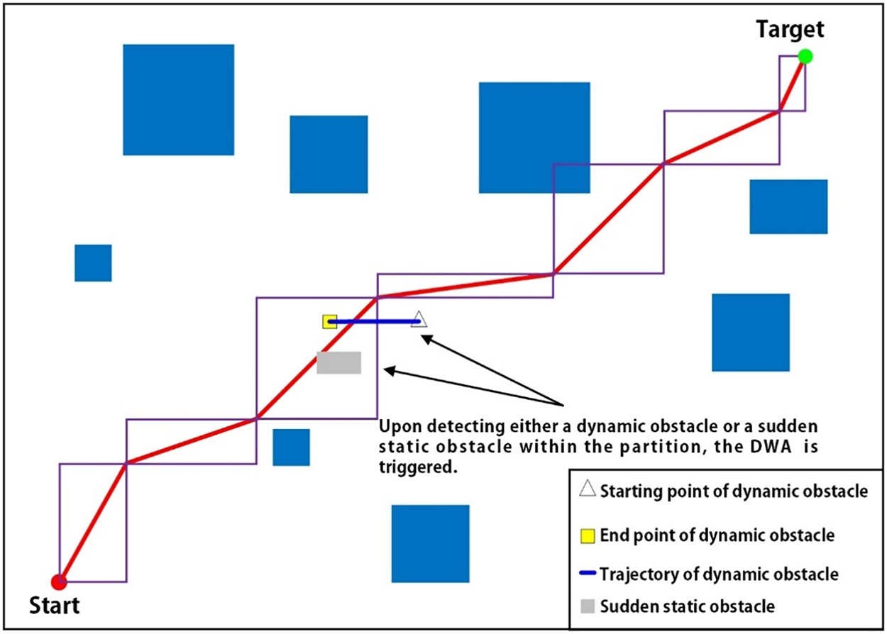
Figure 8: Schematic diagram of the partitioned DWA
To provide a clear formal definition of the partitioned detection process, the rectangular subregions constructed along the global path are parameterized as follows. Let the global path consist of a sequence of consecutive waypoints:
where each
Each rectangular subregion
where
The geometric dimensions of each rectangular subregion are determined by the distance between the corresponding consecutive global path waypoints, and the principal axis of the rectangle is aligned along the vector pointing from the start corner to the end corner.
When the robot enters a rectangular subregion
where
The size of the rectangular subregions, as illustrated in Fig. 8, directly affects system performance in two main aspects:
(1) Too large subregions: A single subregion may contain excessive obstacles, which increases the overall path planning time.
(2) Too small subregions: If a subregion is too short, the system will update subregions too frequently, leading to increased computational overhead.
This method provides theoretical guarantees: local replanning is completed within a finite time, and combined with the retreat mechanism, it prevents the robot from entering infinite loops. Furthermore, the SSA* global path provides an initial feasible route, and together with the DWA’s velocity constraints and safety buffers, ensures that the robot maintains a safe distance in dynamic environments. In this way, the partitioned PDWA enables real-time obstacle avoidance and trajectory optimization under the guidance of global planning, ensuring the safety, smoothness, and executability of path planning.
To ensure the accuracy and reliability of the results, all experiments were repeatedly performed under identical conditions. The data presented in this paper represent the averaged results from multiple repeated trials.
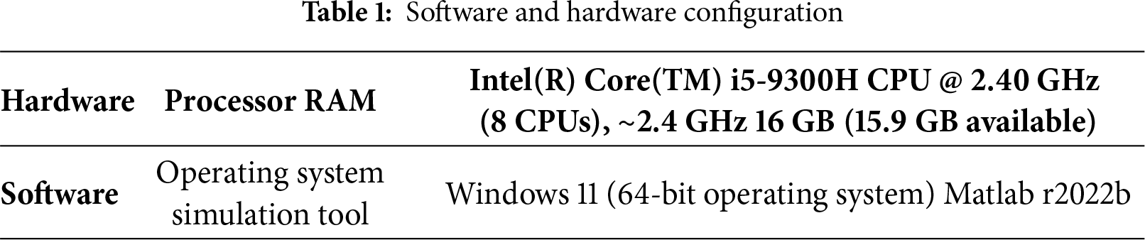
5.1 Experimental Hardware and Software Configuration
All experimental environments in this paper are shown in Table 1.
5.2 Static Path Planning Experiments
To evaluate the performance of the SSA* algorithm in static environments, satellite maps of real-world scenes were used (Fig. 9a), where black regions represent obstacles and white regions are free areas. Experiments were conducted on grid maps with different resolutions (25 × 25, 50 × 50, 100 × 100). The SSA* algorithm was compared to the conventional A* algorithm based on the following criteria: path length, number of expanded nodes, computation time, number of turning points, and number of risky nodes (near obstacles).
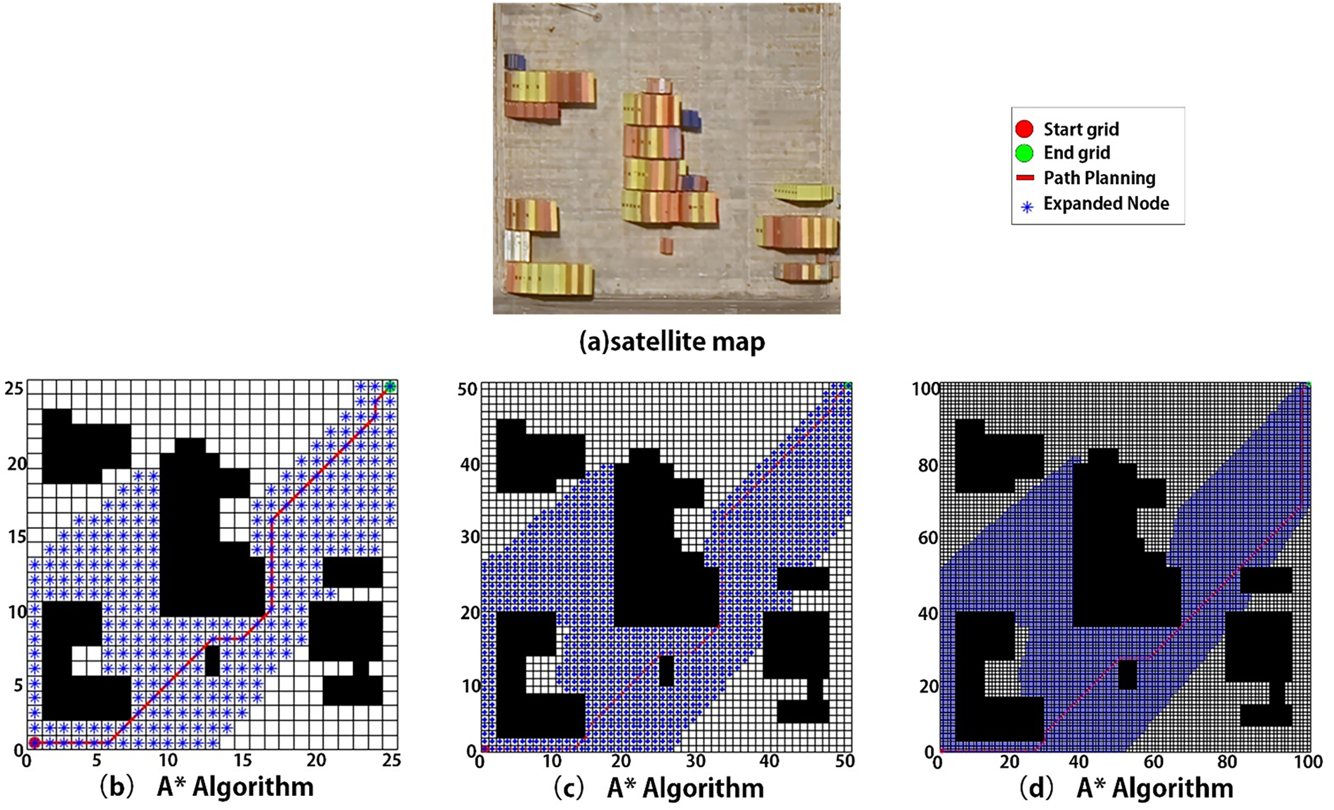
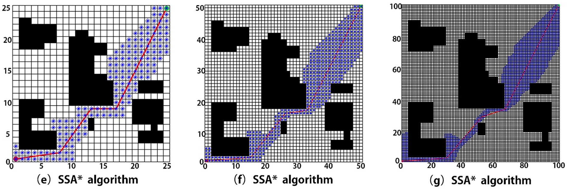
Figure 9: Comparison of path results between traditional A* Algorithm and SSA* Algorithm (a) satellite map (b) 25 × 25 grid map of A* Algorithm (c) 50 × 50 grid map of A* Algorithm (d) 100 × 100 grid map of A* Algorithm (e) 25 × 25 grid map of SSA* Algorithm (f) 50 × 50 grid map of SSA* Algorithm (g) 100 × 100 grid map of SSA* Algorithm
Fig. 9b–d shows the conventional A* results, and Fig. 9e–g shows the SSA* results. The comparison highlights several key points:
(1) The conventional A* algorithm expands many redundant nodes, reducing search efficiency.
(2) The SSA* algorithm, with an optimized heuristic function, significantly reduces node expansion and narrows the search range.
(3) The SSA* generates smoother paths with fewer turning points and better obstacle avoidance near boundaries.
Table 2 compares the performance of the two algorithms. Under identical environment and parameter settings, multiple repeated experiments were conducted. The results show that the SSA* algorithm expands fewer nodes, requires less computation time, and generates shorter, more efficient, and safer paths. In addition, it avoids risky nodes and produces smoother trajectories with fewer turns.
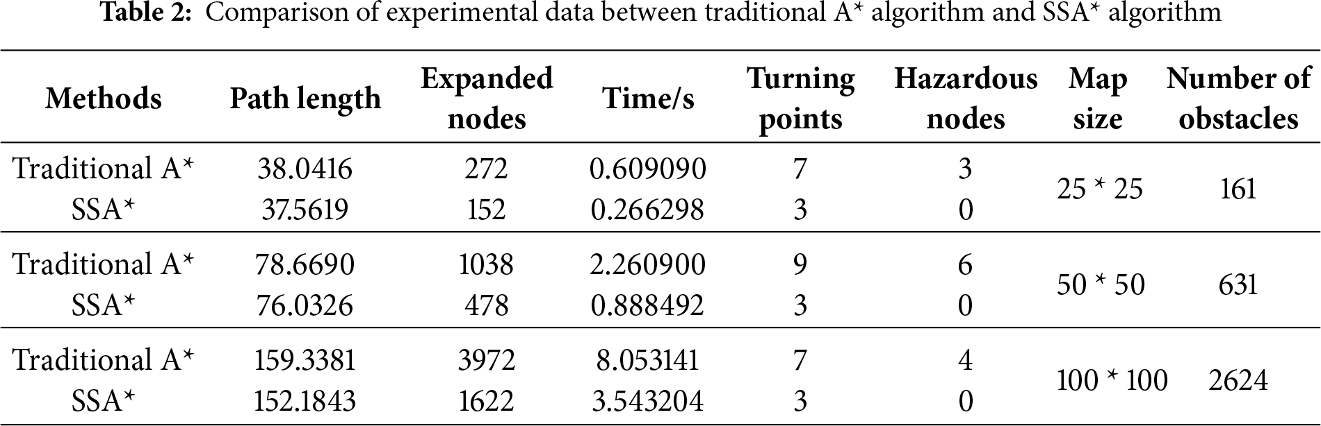
In conclusion, the results obtained from multiple independent repeated experiments demonstrate that the SSA* algorithm outperforms the conventional A* algorithm in both efficiency and path quality, providing a solid foundation for subsequent experiments in dynamic environments.
5.3 Dynamic Path Planning Comparison
In this experiment, Fig. 10a presents the satellite view of the port environment. Several graph-search-based algorithms combined with the DWA and independent dynamic planning algorithms were compared in dynamic environments. However, some recent algorithms are still experimental and depend on specific hardware or deep learning frameworks, with fluctuating performance across different simulation environments. In contrast, the classical graph search and DWA-based algorithms in this study offer stable implementations and controlled performance evaluation. Fig. 10b–h shows the results of the proposed SSA*–PDWA, Dijkstra–DWA, BFS–DWA, A*–DWA, DFS–DWA, D*, and standalone DWA algorithms, respectively.
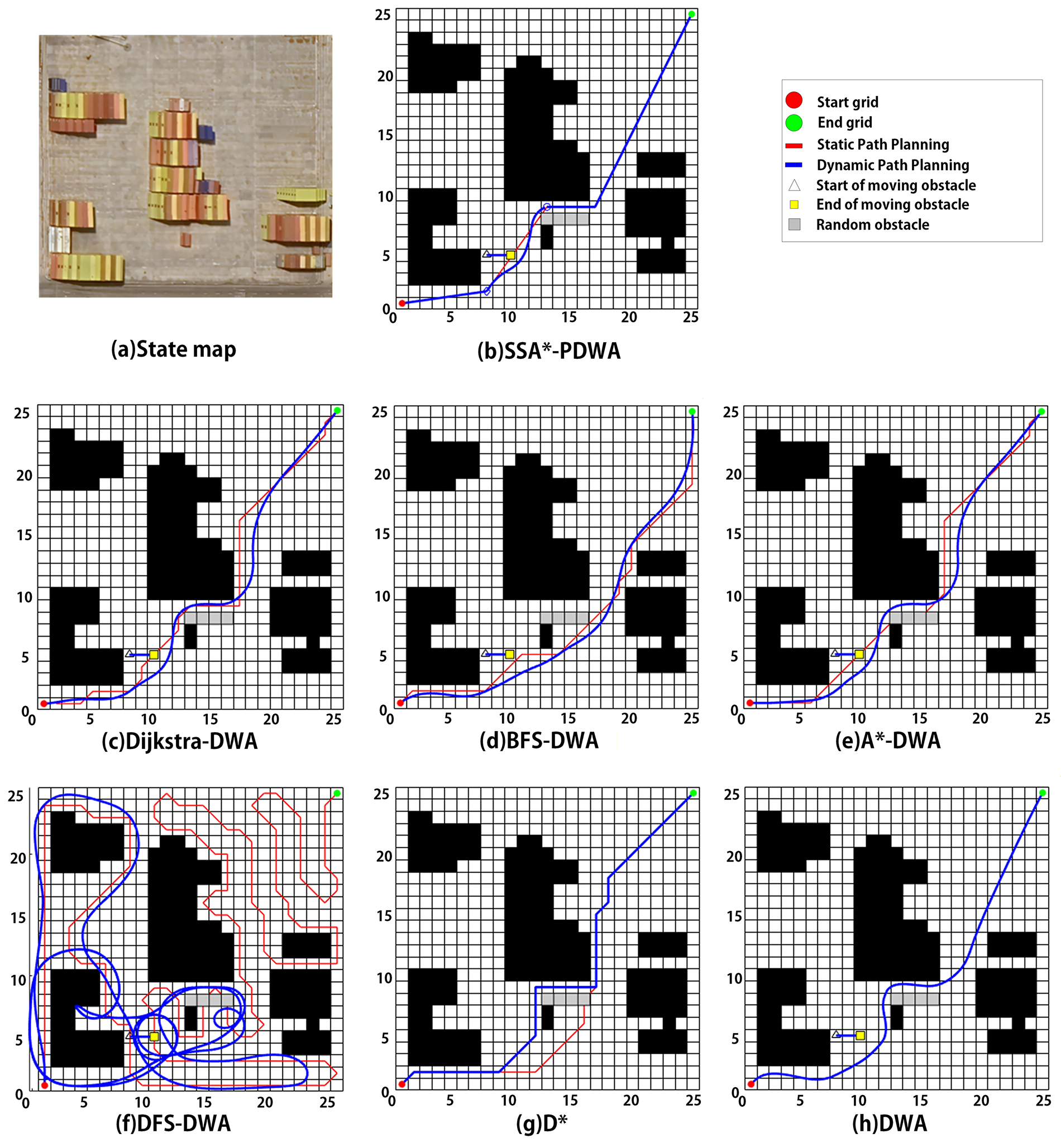
Figure 10: Comparison of path planning results among seven algorithms (a) State map (b) SSA*-PDWA (c) Dijkstra-DWA (d) BFS-DWA (e) A*-DWA (f) DFS-DWA (g) D* (h) DWA
To verify the statistical significance of the performance differences among the algorithms, this study conducted a Wilcoxon rank-sum test based on the results of 30 independent trials. This non-parametric test was used to compare the proposed method with the baseline algorithms in terms of the distributions of key performance metrics, with the significance level set to 0.05. The experimental results demonstrate that, with respect to core metrics such as path length, minimum safety distance, success rate, and collision rate, the proposed SSA-PDWA* algorithm exhibits statistically significant superior performance (p < 0.05) compared with the competing methods, thereby confirming its robustness and safety advantages in complex dynamic environments.
The results in Table 3 show that the SSA*–PDWA algorithm excels in path planning. It generates the shortest path of 37.9708, outperforming all other methods, and achieves the lowest computation time of 3.97 s, demonstrating superior real-time performance. The significantly lower computation time is primarily attributed to the partitioning strategy of PDWA. By dividing the environment into local subregions, dynamic path planning is performed only within a limited local area, effectively reducing both the path length and the computational load required for each replanning step. Since dynamic path planning itself is computationally expensive, traditional global or standalone DWA performs dynamic planning along the entire path, resulting in substantially longer computation times. SSA*–PDWA maintains stable path generation across various obstacles, offering a better balance between adaptability and path quality. Overall, it is more efficient with shorter paths and faster computation times.
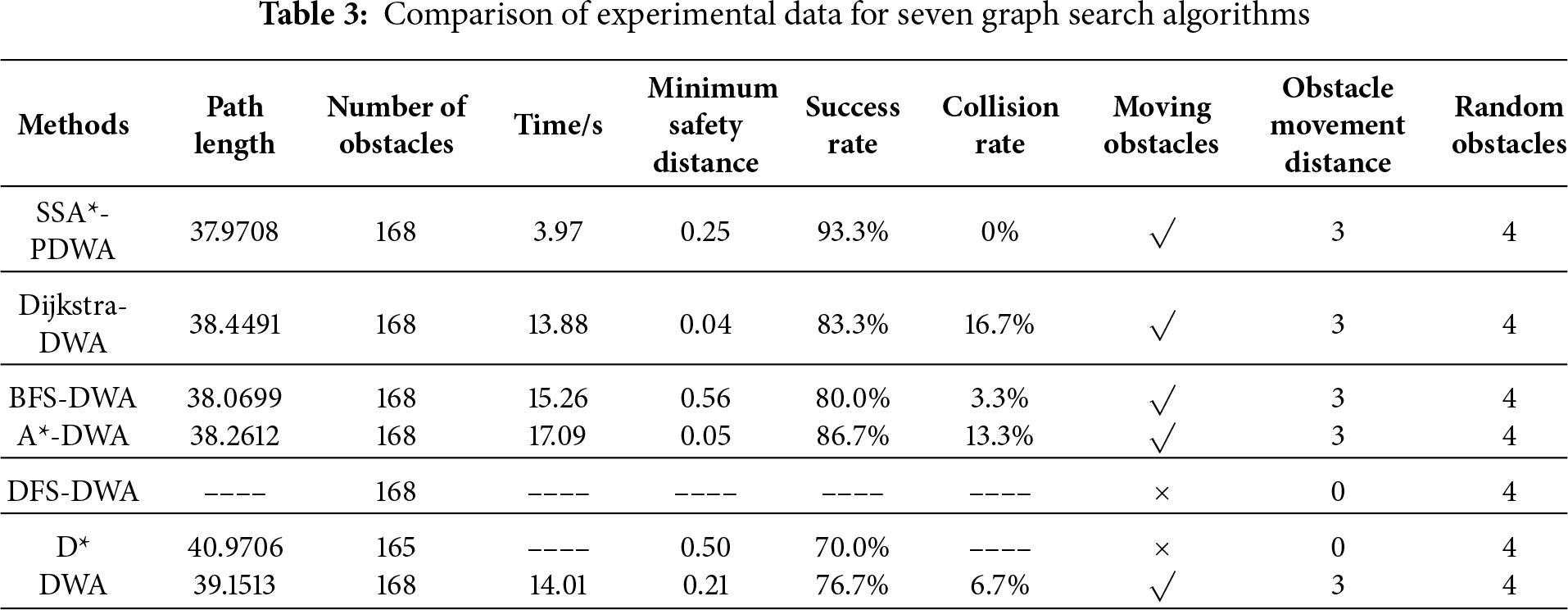
Notably, the D* algorithm fails to avoid dynamic obstacles, and DFS and DWA struggled with excessively long or irregular paths in this experiment, further highlighting DWA’s limitations in long-distance tasks, where it may lead to detours or collisions.
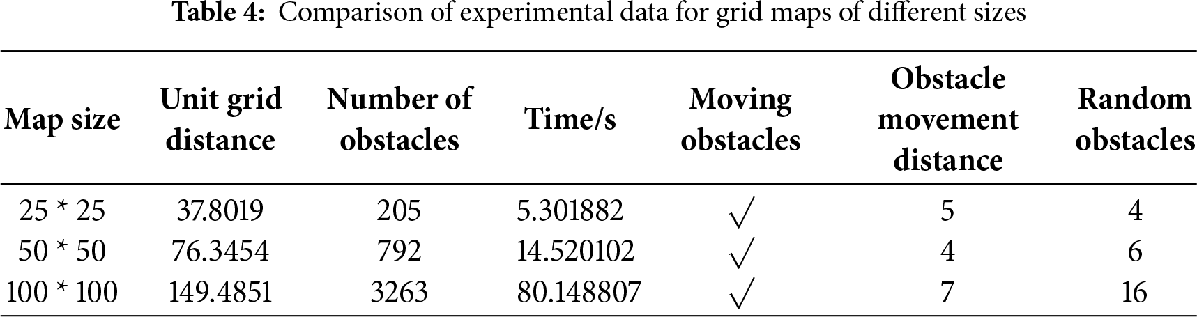
5.4 Comparison across Different Grid Map Sizes
To demonstrate the scalability of the proposed algorithm, the satellite map (as shown in Fig. 11) was converted into grid maps with three different resolutions, while maintaining the same dynamic elements and randomly distributed obstacles. The path planning results are shown in Fig. 12. In Table 4, planning time exhibits nonlinear growth with increasing resolution. For the A* algorithm, the number of node expansions increases sharply as the number of grid cells grows. Meanwhile, during execution, DWA incurs additional computational load due to the increased velocity sampling and collision detection, which scale with both the number of path steps and the density of local obstacles.
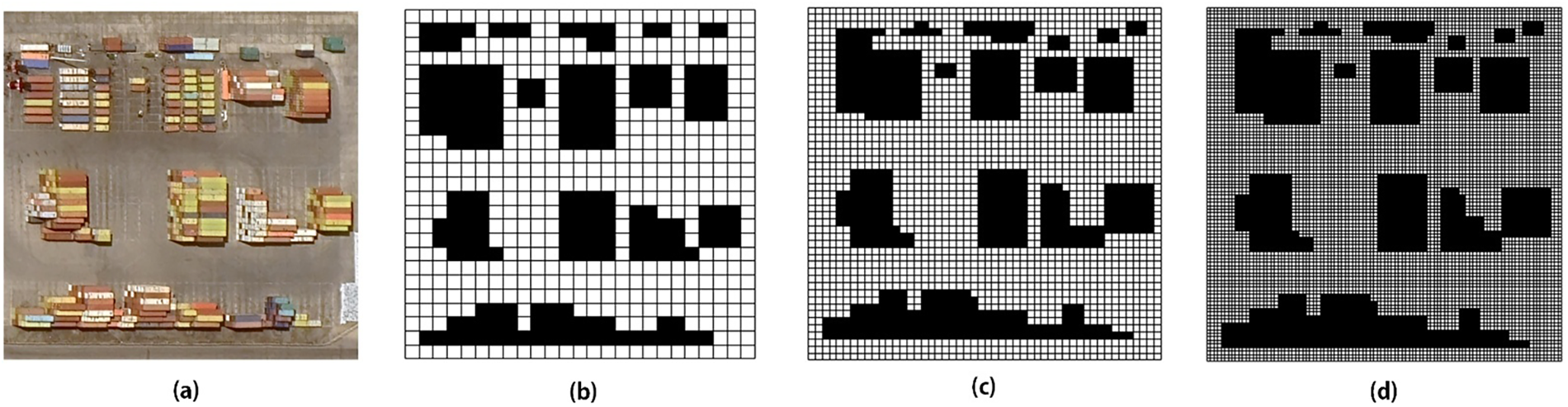
Figure 11: Three different sizes of grid maps (a) Satellite Map of Port (b) 25 × 25 grid map (c) 50 × 50 grid map (d) 100 × 100 grid map
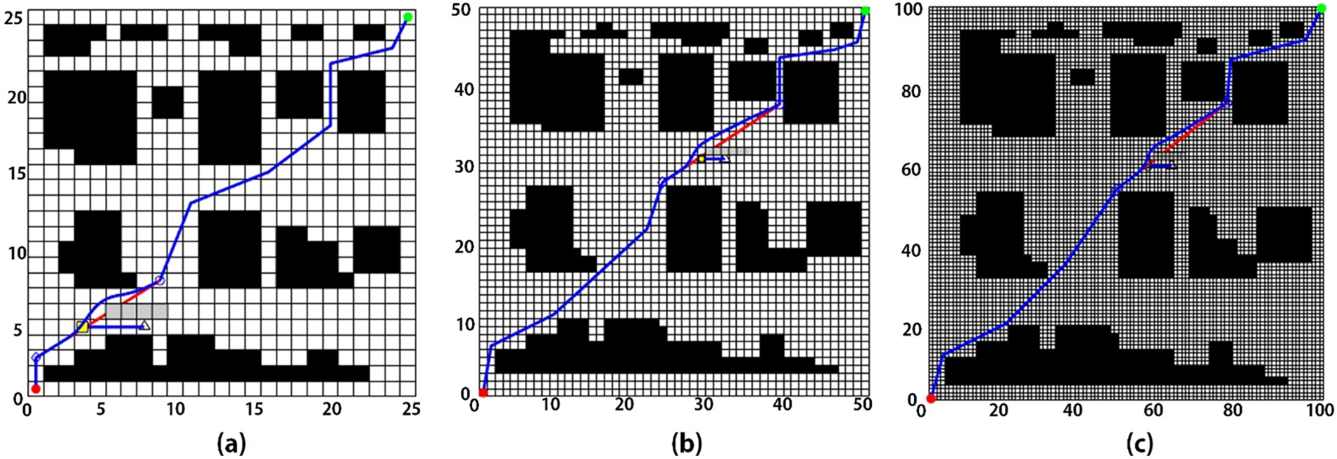
Figure 12: Comparison of paths in grid maps with three different sizes (a) 25 × 25 grid map path planning (b) 50 × 50 grid map path planning (c) 100 × 100 grid map path planning
5.5 Comparison across Different Scenarios
To further verify the adaptability and robustness of the proposed algorithm in various port scenarios, three representative cases were selected and converted into 100 × 100 grid maps, as illustrated in Fig. 13a–c correspond to the satellite maps (Map1–Map3) of three different ports and their corresponding grid maps Fig. 13d–f.
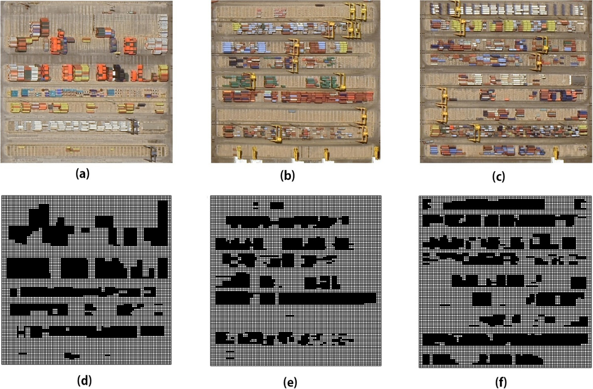
Figure 13: Satellite maps of ports in three different scenarios (a) Satellite Map1 (b) Satellite Map2 (c) Satellite Map3 (d) 100 × 100 grid Map1 (e) 100 × 100 grid Map2 (f) 100 × 100 grid Map3
To ensure that the planned routes maintain a consistent direction across all test environments, the starting point was uniformly set to the minimum coordinate of the grid map, (0, 0), and the goal point to the maximum coordinate, (100, 100). This configuration eliminates the influence of differing start–goal placements and ensures that the three experimental setups provide a fair and consistent basis for performance comparison, thereby offering a more objective assessment of path planning effectiveness across distinct port environments.
The path planning results are illustrated in the Fig. 14, while the corresponding experimental performance metrics are summarized in the Table 5. The tests on Map1–Map3 demonstrate that the proposed algorithm can generate reasonable and feasible paths across different port environments with varying levels of complexity, while exhibiting only minor fluctuations in path length. The planning time was found to be closely related to factors such as the number of obstacles, their spatial density, and the degree of local constraints.
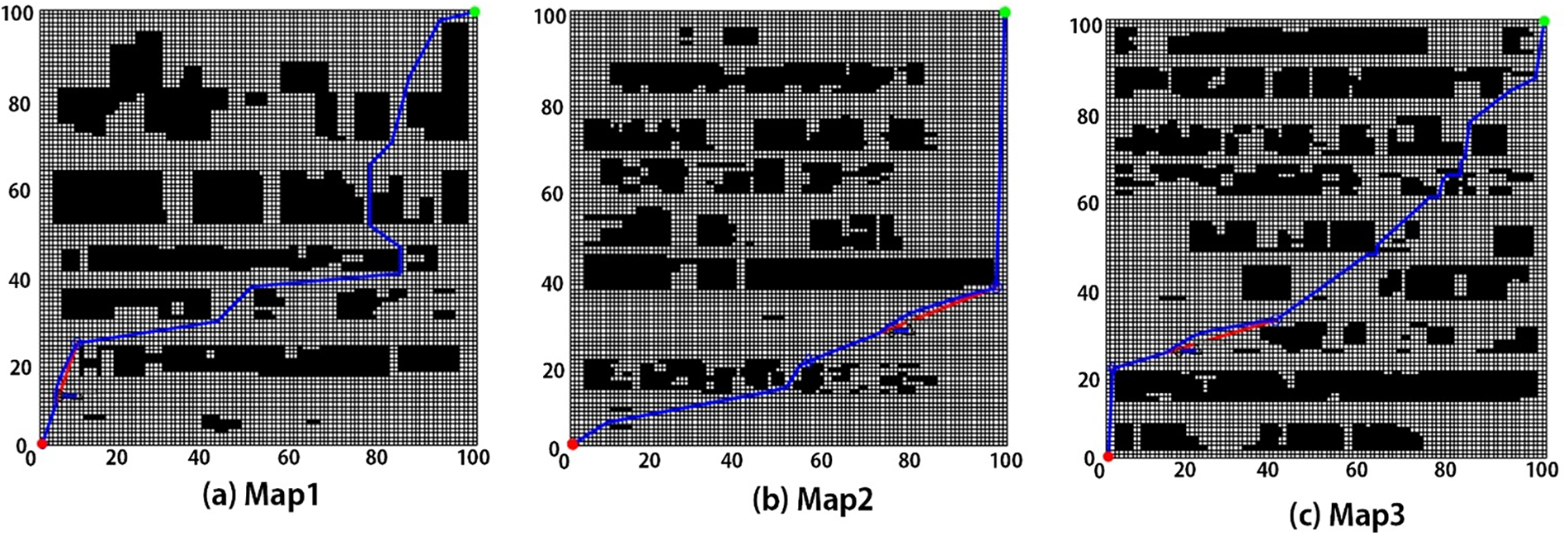
Figure 14: Comparison of paths in grid maps of three different scenarios (a) Map1 (b) Map2 (c) Map3
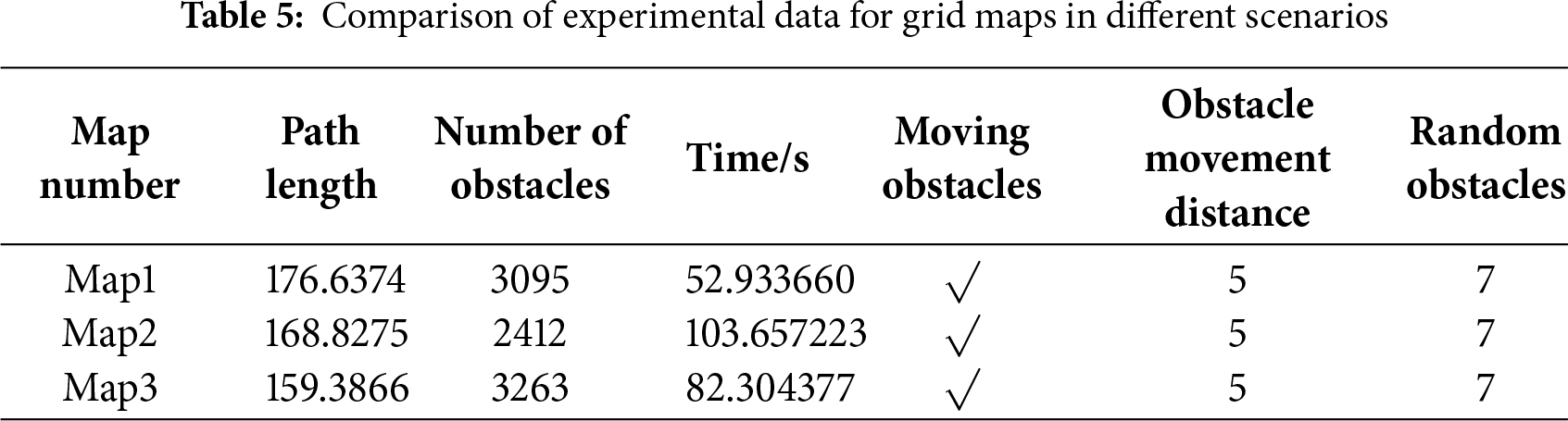
Moreover, when faced with dynamic and randomly moving obstacles, the algorithm consistently maintained path feasibility, further confirming its robustness and practicality. Therefore, the proposed method is not only effective in idealized environments but also maintains stable performance in complex real-world port scenarios, demonstrating strong potential for practical application and broader deployment.
This study proposes an intelligent path planning algorithm based on SSA* and PDWA to address the navigation challenges of mobile robots in complex dynamic environments. Its performance improvement lies in the synergistic optimization at the mechanism level: at the global level, SSA* incorporates obstacle inflation and safety-cost modeling, embedding safety margins and path smoothness directly into the search process. This ensures that the generated paths are structurally more continuous, stable, and distant from obstacle edges, effectively reducing the burden on local obstacle avoidance and the frequency of replanning. At the local level, the partition-based PDWA triggering mechanism activates dynamic obstacle avoidance only in potential conflict regions, effectively preventing path oscillations and efficiency loss caused by traditional DWA frequently adjusting velocities in interference-free areas. Experimental results demonstrate that the proposed method outperforms conventional algorithms in terms of path length, computation time, and safety, and maintains stable performance across different grid resolutions and port scenarios, verifying its scalability and practical applicability. Overall, the “SSA* + PDWA” hybrid framework, through a dual-layer mechanism of “global structural optimization + local intelligent response,” achieves an efficient balance between global optimality and real-time adaptability, providing a high-performance solution with enhanced robustness and practical value for autonomous navigation of AGVs in complex port environments.
Acknowledgement: Not applicable.
Funding Statement: The authors received no specific funding for this study.
Author Contributions: Lishu Qin contributed to algorithm design and global path planning. Yu Gao contributed to local path planning and experimental analysis. Xinyuan Lu contributed to simulation, visualization, and result validation. All authors reviewed the results and approved the final version of the manuscript.
Availability of Data and Materials: The data that support the findings of this study are available from the corresponding author upon reasonable request.
Ethics Approval: Not applicable.
Conflicts of Interest: The authors declare no conflicts of interest to report regarding the present study.
References
1. Qin L, Gao Y, Zheng Y. GO-GASA: grid optimization genetic A* algorithm for mobile robots path planning utilizing grid optimization. IEEE Access. 2025;13:126557–73. doi:10.1109/access.2025.3587069. [Google Scholar] [CrossRef]
2. Kumar A, Zhang L, Bilal H, Wang S, Shaikh AM, Bo L, et al. DSQN: robust path planning of mobile robot based on deep spiking Q-network. Neurocomputing. 2025;634:129916. doi:10.1016/j.neucom.2025.129916. [Google Scholar] [CrossRef]
3. Lackner T, Hermann J, Kuhn C, Palm D. Review of autonomous mobile robots in intralogistics: state-of-the-art, limitations and research gaps. Procedia CIRP. 2024;130:930–5. doi:10.1016/j.procir.2024.10.187. [Google Scholar] [CrossRef]
4. AbuJabal N, Baziyad M, Fareh R, Brahmi B, Rabie T, Bettayeb M. A comprehensive study of recent path-planning techniques in dynamic environments for autonomous robots. Sensors. 2024;24(24):8089. doi:10.3390/s24248089. [Google Scholar] [PubMed] [CrossRef]
5. Ambuj, Machavaram R. Intelligent path planning for autonomous ground vehicles in dynamic environments utilizing adaptive Neuro-Fuzzy control. Eng Appl Artif Intell. 2025;144:110119. doi:10.1016/j.engappai.2025.110119. [Google Scholar] [CrossRef]
6. Chen P, Pei J, Lu W, Li M. A deep reinforcement learning based method for real-time path planning and dynamic obstacle avoidance. Neurocomputing. 2022;497:64–75. doi:10.1016/j.neucom.2022.05.006. [Google Scholar] [CrossRef]
7. Luo Y, Lin S, Wang Y, Liang K. Optimized path planning for autonomous guided vehicle through fusion of improved A* and dynamic window approach. IEEE Access. 2025;13:68577–86. doi:10.1109/access.2025.3561005. [Google Scholar] [CrossRef]
8. Wang Z, Li G. Research on path planning algorithm of driverless ferry vehicles combining improved A* and DWA. Sensors. 2024;24(13):4041. doi:10.3390/s24134041. [Google Scholar] [PubMed] [CrossRef]
9. Shanmugaraja M, Thangamuthu M, Ganesan S. Hybrid path planning algorithm for autonomous mobile robots: a comprehensive review. J Sens Actuator Netw. 2025;14(5):87. doi:10.3390/jsan14050087. [Google Scholar] [CrossRef]
10. Ren X, Wang Z, Tang J. Mobile robot path planning based on improved A* algorithm fused with JPS. In: Proceedings of the 2024 3rd International Symposium on Control Engineering and Robotics; 2024 May 24–26; Changsha, China. New York, NY, USA: The Association for Computing Machinery (ACM); 2024. p. 478–85. doi:10.1145/3679409.3679499. [Google Scholar] [CrossRef]
11. Liu Z, Guo S, Yu F, Hao J, Zhang P. Improved A* algorithm for mobile robots under rough terrain based on ground trafficability model and ground ruggedness model. Sensors. 2024;24(15):4884. doi:10.3390/s24154884. [Google Scholar] [PubMed] [CrossRef]
12. Miyombo ME, Liu YK, Mulenga CM, Siamulonga A, Kabanda MC, Shaba P, et al. Optimal path planning in a real-world radioactive environment: a comparative study of A-star and Dijkstra algorithms. Nucl Eng Des. 2024;420:113039. doi:10.1016/j.nucengdes.2024.113039. [Google Scholar] [CrossRef]
13. Zhang J, Zhu Z, Xue Y, Deng Z, Qin H. Local path planning of under-actuated AUV based on VADWA considering dynamic model. Ocean Eng. 2024;310:118705. doi:10.1016/j.oceaneng.2024.118705. [Google Scholar] [CrossRef]
14. Tao B, Kim JH. Deep reinforcement learning-based local path planning in dynamic environments for mobile robot. J King Saud Univ Comput Inf Sci. 2024;36(10):102254. doi:10.1016/j.jksuci.2024.102254. [Google Scholar] [CrossRef]
15. Dobrevski M, Skočaj D. Dynamic adaptive dynamic window approach. IEEE Trans Robot. 2024;40:3068–81. doi:10.1109/tro.2024.3400932. [Google Scholar] [CrossRef]
16. Chen X, Yang C, Hu H, Gao Y, Zhu Q, Shao G. A hybrid DWA-MPC framework for coordinated path planning and collision avoidance in articulated steering vehicles. Machines. 2024;12(12):939. doi:10.3390/machines12120939. [Google Scholar] [CrossRef]
17. Liao T, Chen F, Wu Y, Zeng H, Ouyang S, Guan J. Research on path planning with the integration of adaptive A-star algorithm and improved dynamic window approach. Electronics. 2024;13(2):455. doi:10.3390/electronics13020455. [Google Scholar] [CrossRef]
18. Dao TK, Ngo TG, Pan JS, Nguyen TTT, Nguyen TT. Enhancing path planning capabilities of automated guided vehicles in dynamic environments: multi-objective PSO and dynamic-window approach. Biomimetics. 2024;9(1):35. doi:10.3390/biomimetics9010035. [Google Scholar] [PubMed] [CrossRef]
19. Zhang W, Li W, Zheng X, Sun B. Improved A* and DWA fusi on algorithm based path planning for intelligent substation inspection robot. Meas Control. 2025;20:00202940251316687. doi:10.1177/00202940251316687. [Google Scholar] [CrossRef]
20. Gu C, Liu S, Li H, Yuan K, Bao W. Research on hybrid path planning of underground degraded environment inspection robot based on improved A* algorithm and DWA algorithm. Robotica. 2025;43(3):887–908. doi:10.1017/s0263574725000037. [Google Scholar] [CrossRef]
21. Park HM, Cho SW, Seo KM. Hybrid path planning framework to integrate improved A*-DWA algorithms for enhancing path safety and efficiency. Appl Ocean Res. 2025;157:104497. doi:10.1016/j.apor.2025.104497. [Google Scholar] [CrossRef]
22. Xu Y, Liu W. Enhanced A*–fuzzy DWA hybrid algorithm for AGV path planning in confined spaces. World Electr Veh J. 2025;16(9):538. doi:10.3390/wevj16090538. [Google Scholar] [CrossRef]
23. Lu Y, Da C. Global and local path planning of robots combining ACO and dynamic window algorithm. Sci Rep. 2025;15(1):9452. doi:10.1038/s41598-025-93571-8. [Google Scholar] [PubMed] [CrossRef]
24. Dang TV. Optimization hybrid path planning based on a-star algorithm combining with dwa. MM Sci J. 2024;10:7551–5. doi:10.17973/mmsj.2024_10_2024077. [Google Scholar] [CrossRef]
25. Zhou Z, Chen M, Wang Y, Huang S, Lim EG. A hybrid algorithm for dynamic path planning of mobile robot using improved A* and DWA. In: Advances in mechanical design. Singapore: Springer Nature; 2024. p. 2483–503. doi:10.1007/978-981-97-0922-9_158. [Google Scholar] [CrossRef]
26. Li Q, Huang Z, Jiang W, Tang Z, Song M. Quantum algorithms using infeasible solution constraints for collision-avoidance route planning. IEEE Trans Consumer Electron. 2025;71(1):2186–201. doi:10.1109/tce.2024.3476156. [Google Scholar] [CrossRef]
27. Fei C, Lu Z, Jiang W. Heuristic optimization-based trajectory planning for UAV swarms in urban target strike operations. Drones. 2024;8(12):777. doi:10.3390/drones8120777. [Google Scholar] [CrossRef]
28. Shi Y, Huang S, Li M. An improved global and local fusion path-planning algorithm for mobile robots. Sensors. 2024;24(24):7950. doi:10.3390/s24247950. [Google Scholar] [PubMed] [CrossRef]
29. Han L, He L, Sun X, Li Z, Zhang Y. An enhanced adaptive 3D path planning algorithm for mobile robots with obstacle buffering and improved Theta* using minimum snap trajectory smoothing. J King Saud Univ Comput Inf Sci. 2023;35(10):101844. doi:10.1016/j.jksuci.2023.101844. [Google Scholar] [CrossRef]
30. Yu J, Nguyen TT, Dao TK, Nguyen TT. Global path planning algorithm for mobile robots: a review. Netw Intell. 2024;9:643–57. doi:10.3390/s21237898. [Google Scholar] [PubMed] [CrossRef]
31. Sun Y, Yuan Q, Gao Q, Xu L. A multiple environment available path planning based on an improved A* algorithm. Int J Comput Intell Syst. 2024;17(1):172. doi:10.1007/s44196-024-00571-z. [Google Scholar] [CrossRef]
32. Guo R, Quan X, Bao C. Research on mobile robot path planning based on an improved bidirectional jump point search algorithm. Electronics. 2025;14(8):1669. doi:10.3390/electronics14081669. [Google Scholar] [CrossRef]
33. Rahaman MF, Li X, Sunny MNM, Atayeva J, Islam MS. The improved A* algorithm for mobile robots: node optimization and advanced evaluation function. In: Proceedings of the 2024 10th International Conference on Mechanical and Electronics Engineering (ICMEE); 2024 Dec 27–29; Xi’an, China. p. 220–5. doi:10.1109/icmee63700.2024.11025311. [Google Scholar] [CrossRef]
34. Psotka M, Duchoň F, Roman M, Michal T, Michal D. Global path planning method based on a modification of the wavefront algorithm for ground mobile robots. Robotics. 2023;12(1):25. doi:10.3390/robotics12010025. [Google Scholar] [CrossRef]
35. Tang Y, Zakaria MA, Younas M. Path planning trends for autonomous mobile robot navigation: a review. Sensors. 2025;25(4):1206. doi:10.3390/s25041206. [Google Scholar] [PubMed] [CrossRef]
36. Lai X, Wu D, Wu D, Li JH, Yu H. Enhanced DWA algorithm for local path planning of mobile robot. Ind Robot Int J Robot Res Appl. 2023;50(1):186–94. doi:10.1108/ir-05-2022-0130. [Google Scholar] [CrossRef]
37. Liu Y, Wang C, Wu H, Wei Y. Mobile robot path planning based on kinematically constrained A-star algorithm and DWA fusion algorithm. Mathematics. 2023;11(21):4552. doi:10.3390/math11214552. [Google Scholar] [CrossRef]
38. Cao Y, Mohamad Nor N. An improved dynamic window approach algorithm for dynamic obstacle avoidance in mobile robot formation. Decis Anal J. 2024;11:100471. doi:10.1016/j.dajour.2024.100471. [Google Scholar] [CrossRef]
39. Wang Y, Fu C, Huang R, Tong K, He Y, Xu L. Path planning for mobile robots in greenhouse orchards based on improved A* and fuzzy DWA algorithms. Comput Electron Agric. 2024;227:109598. doi:10.1016/j.compag.2024.109598. [Google Scholar] [CrossRef]
40. Hahn B. Enhancing obstacle avoidance in dynamic window approach via dynamic obstacle behavior prediction. Actuators. 2025;14(5):207. doi:10.3390/act14050207. [Google Scholar] [CrossRef]
41. Li P, Hao L, Zhao Y, Lu J. Robot obstacle avoidance optimization by A* and DWA fusi on algorithm. PLoS One. 2024;19(4):e0302026. doi:10.1371/journal.pone.0302026. [Google Scholar] [PubMed] [CrossRef]
42. Badrloo S, Varshosaz M, Pirasteh S, Li J. Image-based obstacle detection methods for the safe navigation of unmanned vehicles: a review. Remote Sens. 2022;14(15):3824. doi:10.3390/rs14153824. [Google Scholar] [CrossRef]
Cite This Article
 Copyright © 2026 The Author(s). Published by Tech Science Press.
This work is licensed under a Creative Commons Attribution 4.0 International License , which permits unrestricted use, distribution, and reproduction in any medium, provided the original work is properly cited.
 Downloads
 Citation Tools