
 Submit a Paper
 Propose a Special lssue
 Open Access
ARTICLE

A Secure Task Offloading Scheme for UAV-Assisted MEC with Dynamic User Clustering and Cooperative Jamming: A Method Combining K-Means and SAC (K-SAC)
1 School of Computer Science and Information Security, Guilin University of Electronic Technology, Guilin, China
2 Faculty Development and Teaching Evaluation Center, Civil Aviation Flight University of China, Guanghan, China
3 College of Aviation Electronic and Electrical Engineering, Civil Aviation Flight University of China, Guanghan, China
* Corresponding Author: Huibing Zhang. Email:
(This article belongs to the Special Issue: Advanced Networking Technologies for Intelligent Transportation and Connected Vehicles)
Computers, Materials & Continua 2026, 87(3), 52 https://doi.org/10.32604/cmc.2026.077824
Received 17 December 2025; Accepted 03 February 2026; Issue published 09 April 2026
 View Full Text
 Download PDF
Abstract
In the unmanned aerial vehicle (UAV) assisted edge computing system, the broadcast characteristics of the UAV signal, the high mobility of the UAV, and the limited airborne energy make the task offloading strategy face challenges such as increased risk of information disclosure, limited computing resources, and the trade-off between energy consumption and flight time. To address these issues, we propose a K-means in-depth reinforcement learning algorithm based on Soft Actor-Critic (SAC). The proposed method first leverages the K-means clustering algorithm to determine the optimal deployment of ground jammers based on the final distribution of mobile users. Then, building upon the SAC framework, the Cross-Entropy Method (CEM) global sampling strategy is incorporated into the action output phase to form the K-SAC algorithm. This algorithm aims to maximize system rewards, which holistically balance task offloading delay, energy consumption, and secure offloading rate. Consequently, it jointly optimizes the optimal hovering positions of auxiliary UAVs and the task offloading ratio for each user, leading to an overall performance improvement in system security and efficiency. Finally, compared with current schemes, the system benefits achieved by the proposed scheme were 9.83% higher on average in different computing task sizes, 13.67% higher on average in different task complexities, and 14.63% higher on average in different interference powers.Keywords
The main difference between UAV edge computing [1,2] and ground edge computing is that ground edge computing [3,4] focuses on deploying computing resources on ground devices at the edge of the network to provide users with computing resources. UAV edge computing focuses on integrating computing power into UAV systems. Drone-based computing servers offer greater flexibility than ground deployment [5].
Compared with traditional ground equipment, due to the high altitude of drones, their air to ground or air-to-air communication links are more likely to be line of sight communication links [6]. On the one hand, compared to complex signal propagation methods such as diffraction and reflection, Line of Sight (LoS) transmission has lower channel attenuation, better signal quality, and lower latency [7]. On the other hand, because signals are not easily obstructed by other obstacles, UAVs can act as airborne base stations in line of sight transmission [8], directly communicating with ground users without the need for additional relay equipment, making deployment more flexible. Although line of sight transmission has many advantages, it also faces some challenges. Due to the broadcasting characteristics of wireless communication between drones and the ground, drones are easily vulnerable to malicious attacks or eavesdropping [9], leading to communication security issues such as data leakage. To solve this problem, traditional security mechanisms focus on encryption, authentication, and key management [10]. For example, Xiao et al. [11], Ghribi et al. [12] proposed communications schemes combined blockchain and encryption techniques to building mechanism to ensure the security of drone network communication. Gai et al. [13] and Usman et al. [14] proposed authentication mechanisms to guarantee the security of unmanned aerial vehicle communication. However, The above methods for upper-layer encryption and secure communication do bolster drone communication security, but at the cost of substantial consumption of the drone’s onboard computing and communication resources. With a growing number of communication nodes, securing sufficient resources to handle incoming data offloaded from other users becomes increasingly challenging.
Physical layer secure transmission, which exploits inherent channel properties like fading and noise without relying on complex encryption, offers an efficient solution to enhance security in dynamic UAV networks with limited resources [15,16]. Consequently, it has attracted growing research interest. For instance, Zhou et al. [17] and Lu et al. [18] designed secure communication schemes for UAV mobile edge computing using algorithms such as block coordinate descent and successive convex approximation. However, they did not fully account for the impact of UAV flight energy consumption and environmental obstacles. Similarly, works in [19–21] employed convex optimization and resource allocation techniques to jointly optimize trajectories, power, and task offloading, yet they also overlooked obstacle constraints. To address the vulnerabilities of Line-of-Sight links, researchers in [22,23] proposed iterative optimization and distributed design algorithms, but these often neglected flight energy costs. To address this issue, [24] applied deep reinforcement learning for trajectory and resource optimization, while [25] developed a two-tier robust algorithm to secure transmissions and reduce energy consumption. Nevertheless, these schemes fail to integrate obstacle considerations. Furthermore, Lei et al. [26] leveraged deep reinforcement learning in a NOMA-assisted UAV-MEC system to handle uncertain eavesdroppers and reduce latency and energy consumption. However, this approach relies on an idealized environment without incorporating practical constraints.
Although there has been considerable research on secure offloading in UAV-assisted MEC systems [4,20], effectively balancing security, latency, and energy efficiency in highly dynamic environments remains a challenging issue. These challenges provide research space for further joint optimization. For convenience, we summarize the differences between existing studies and our work in Table 1.
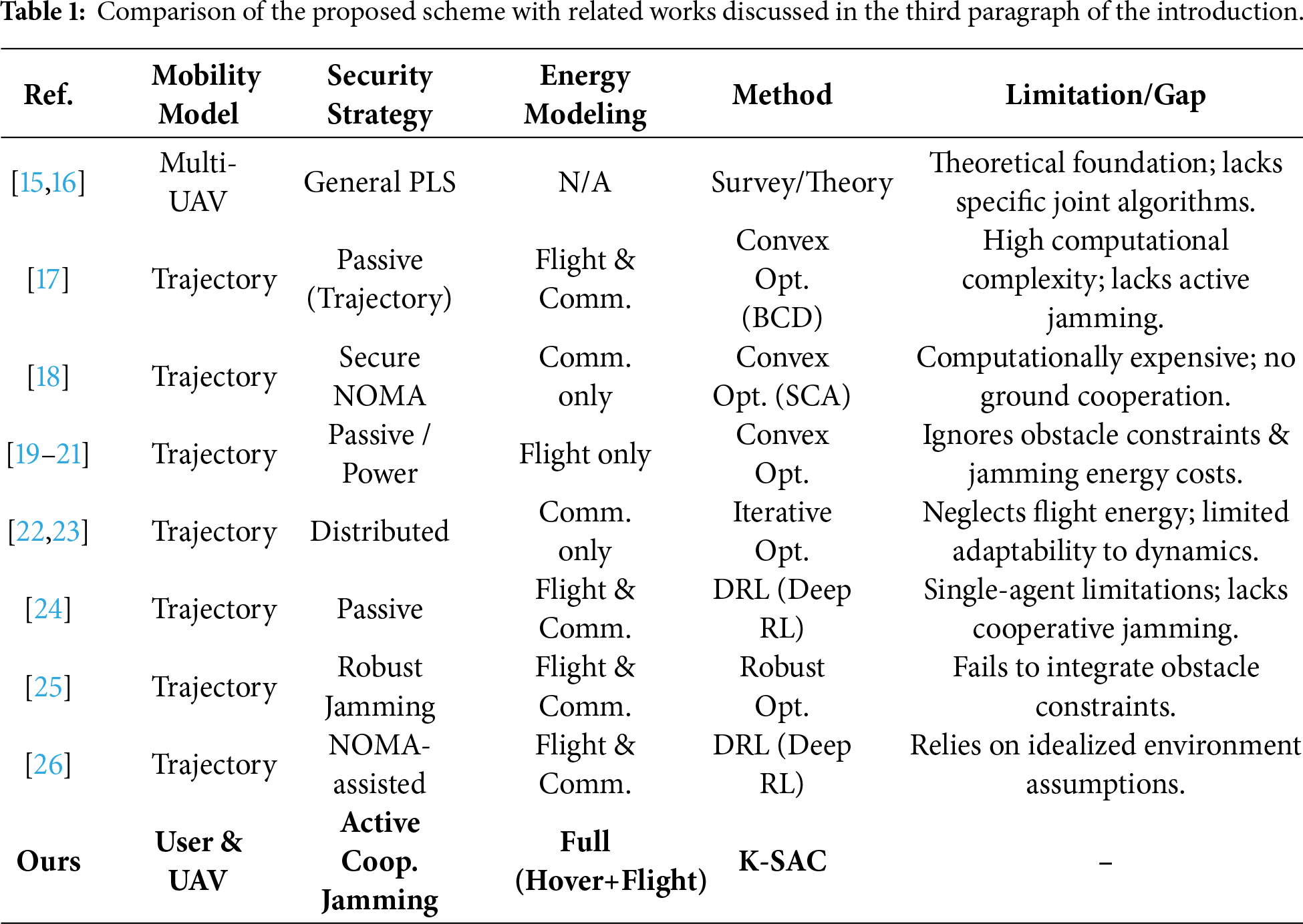
First, most existing risk-aware schemes typically focus on passive risk avoidance—such as selecting communication channels with higher signal-to-noise ratios or relying on fixed ground infrastructure—rather than employing active defense mechanisms. They often overlook the potential of cooperative jamming between auxiliary UAVs and ground jammers, failing to fully utilize interference to degrade the eavesdropper’s channel quality. Second, unlike traditional multi-server MEC environments where servers are static, UAV-assisted systems introduce high mobility. Existing methods often fail to address the dynamic risk variations caused by random user movement and UAV flight, leading to suboptimal offloading decisions when the network topology changes rapidly. Third, the tripartite coupling relationship among secure offloading rate, system delay, and complex energy consumption (including UAV hovering, flight, and jamming) has not been thoroughly analyzed in current multi-server risk models. The existing models often aggregate these energy costs rather than parsing their individual impact on security, compromising the fidelity of optimization results. To address these issues, we propose a K-means-enhanced reinforcement learning algorithm based on the SAC framework. Our method first deploys ground jammers optimally by applying K-means clustering to the final distribution of mobile users. Then, within the SAC framework, we integrate the CEM as a global sampling strategy during the action output phase, forming the so-called K-SAC algorithm.
The main contributions of this paper are as follows:
(1) We construct a novel multi-UAV MEC secure communication framework that integrates ground jammers for active cooperative jamming. Unlike existing models that often treat energy consumption components in isolation, our model establishes a rigorous tripartite coupling relationship among secure offloading rate, system delay, and comprehensive energy costs (including local computation, jamming, edge execution, and UAV hovering/flight). This holistic modeling enables more precise energy-efficiency optimization compared to traditional partial energy models.
(2) To address the challenge of dynamic topology changes caused by random user movement, we propose the K-SAC algorithm, a novel hybrid deep reinforcement learning method. This approach uniquely combines K-means clustering for optimal static jammer deployment with a SAC framework enhanced by CEM global sampling. This hybrid design effectively overcomes the local optima and convergence issues found in traditional DRL algorithms when handling high-dimensional continuous action spaces.
(3) Simulation results confirm the superior performance of the proposed scheme. Compared to existing baselines, it achieves significant and consistent improvements in system utility, with average gains of 9.83% across varying computational task sizes, 13.67% across different task complexities, and 14.63% under diverse interference power levels, demonstrating its comprehensive effectiveness and robustness.
The system model, as illustrated in Fig. 1, examines a secure multi-drone MEC communication network comprising neighboring base stations, auxiliary and intrusion drones, ground jammers, and multiple user devices. Servers outfitted on the adjacent base stations offer computational resources to all users within the system. Intrusion drones act as mobile eavesdroppers, attempting to intercept data during the auxiliary drones’ operation. To counteract this threat, the auxiliary UAV employs a full-duplex mode with a two-antenna setup: one antenna is dedicated to receiving the user’s offloaded signal, while the second simultaneously transmits interference signals toward the invading UAV. Both the user and the invading UAV are equipped with a single antenna for their respective transmission and eavesdropping tasks [22].
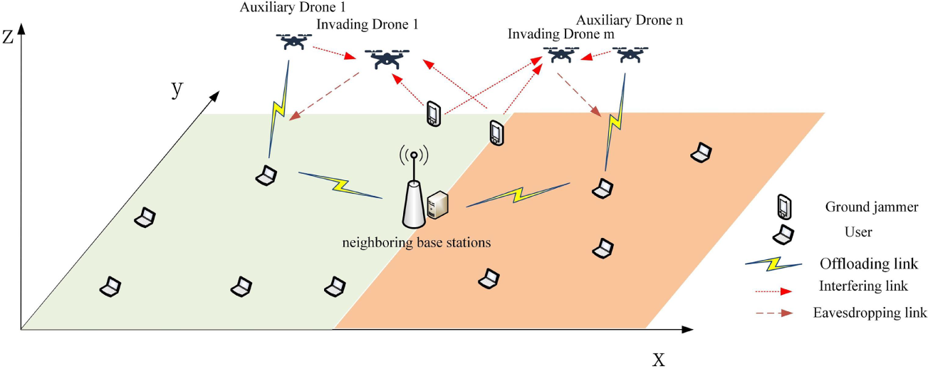
Figure 1: System model diagram.
To further improve security, ground jammers can send interference signals to interfere with invading drones. In addition, in this paper, we consider a multiple access channel where all users can use the same channel to transmit their signals. And assuming the user’s location is fixed, the auxiliary UAV can obtain the location information of eavesdropping nodes and user nodes through devices such as cameras or synthetic aperture radar (SAR) [23,27] installed on the auxiliary UAV.
Following the system model described, we define the collections of entities involved. The system comprises a total of
In this paper, the environment is modeled as dynamic: user equipment undergo random motion with velocity
The distance
The distance
The distance
For the analysis of the air-to-ground link, the connection between the UAV and the user is depicted using a Line of Sight (LoS) model [24]. The gain of the channel is therefore determined via the free space loss model. It is also assumed that the Doppler shift resulting from movement is fully compensated at the receiver. Considering these conditions, the uplink data rate from user ‘
where the index
The interference noise
where
The interference noise
where
The rate of uplink transmission from user device
where
For any user
where
Within the MEC framework, each user device
Accordingly, the local computing latency for user device
Among them,
The time delay caused by assisting UAV
The computational resources of an auxiliary UAV are distributed among users proportionally to the volume of data each user offloads. Consequently, we define
The transmission delay
The delay
where
Since the allocation of base station computing resources is directly proportional to the size of task data offloaded by users to the base station, when the task data size of each user device is the same, it satisfies:
where
Due to the fixed location of the nearby base station, its energy consumption is not considered as it is directly powered by the power supply. At the same time, in order to simplify the model, we consider that the mobile energy consumption of user equipment and ground jammers is provided by additional batteries, and their mobile energy consumption is not considered here. The system energy consumption only considers the user’s local computing energy consumption, ground jammer interference energy consumption, UAV edge computing task execution energy consumption and flight energy consumption. The calculation of flight energy primarily accounts for the power used during both hovering and low-speed, constant-velocity flight. As the energy consumption of low-speed constant speed flight is smaller than that of hovering flight, and the model in this paper finds the optimal hovering position, the drone is in a hovering service state. For the sake of model simplicity, our analysis exclusively accounts for the energy consumed during hovering. The energy
The hovering energy model accounts for several key parameters: the total quantity of rotors
In parallel, we model the computational power (
The energy consumption due to interference from auxiliary drone
The energy consumption of the interference generated by the electromagnetic waves emitted by the ground jammer
Here,
The transmission power consumption between neighboring base stations and user equipment
The computational power of the drone follows the model
The combined average energy expenditure for both user devices and auxiliary drones is given by the following expression:
The overall energy expended by ground jammer
In this paper, we designate
Constraints
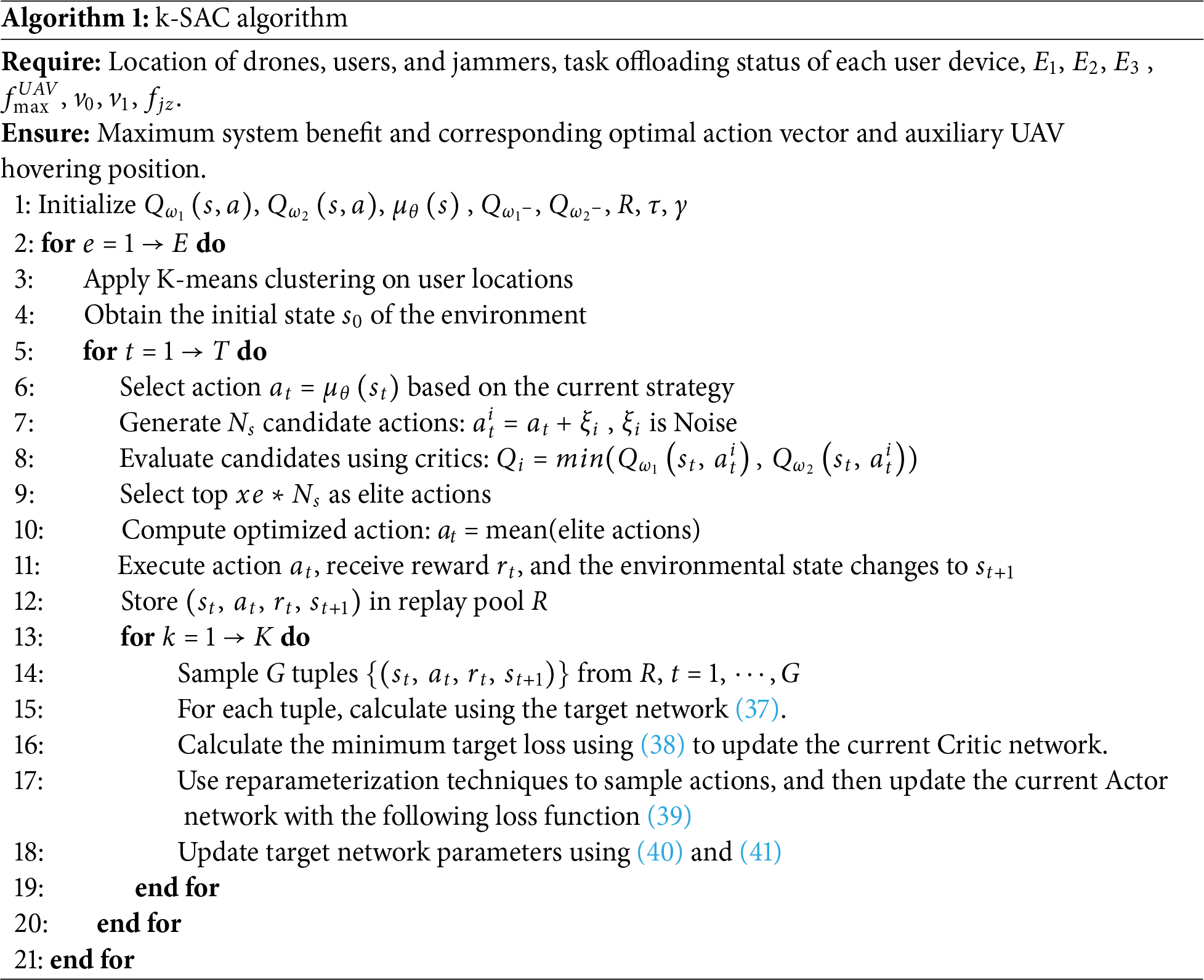
3 K-SAC Algorithm Based on K-Means and SAC
Due to the high-dimensional, dynamic, and non discrete nature of the state space and action space of the optimization objectives in this paper, deep reinforcement learning algorithms are not only more versatile and scalable compared to RL algorithms [31] and traditional objective optimization algorithms, but also perform better in handling complex dynamic systems, long-term planning, and high-dimensional perception tasks. Among numerous deep reinforcement learning algorithms, SAC algorithm not only introduces entropy regularization term to encourage policy exploration of more possibilities, but also allows the use of experience replay, which has stronger exploration ability and higher sample efficiency, making it a powerful tool for solving high-dimensional continuous control tasks. We choose to use the improved SAC algorithm to solve the objective function and obtain the optimal objective value. The global sampling optimization of CEM [32,33] was added to the action distribution generated by the policy network in the SAC algorithm framework. The user device in this paper is movable and its location changes over time, and the optimal placement of the ground jammer will also change accordingly. However, during the task calculation process, their positions remain unchanged. To obtain the optimal target value by solving the objective function, it is necessary to first determine the positions of the user equipment and ground jammers. To solve this problem and ensure the optimal target value within a certain period of time, we combine the K-means algorithm [34,35] with the SAC algorithm to construct the K-SAC algorithm.
Fig. 2 illustrates the structure of the K-SAC algorithm presented herein, which is composed of seven primary components: a proxy, CEM-based global sampling optimization, an experience buffer, a participant network, a criticism network, a target criticism network, and a K-means algorithm. The procedure commences with the K-means algorithm, which determines the ideal placement for the ground jammer by clustering user device locations, thereby establishing the initial interactive setting. Following this, the K-SAC agent inputs this initial environmental state into the participant network to generate a preliminary action,
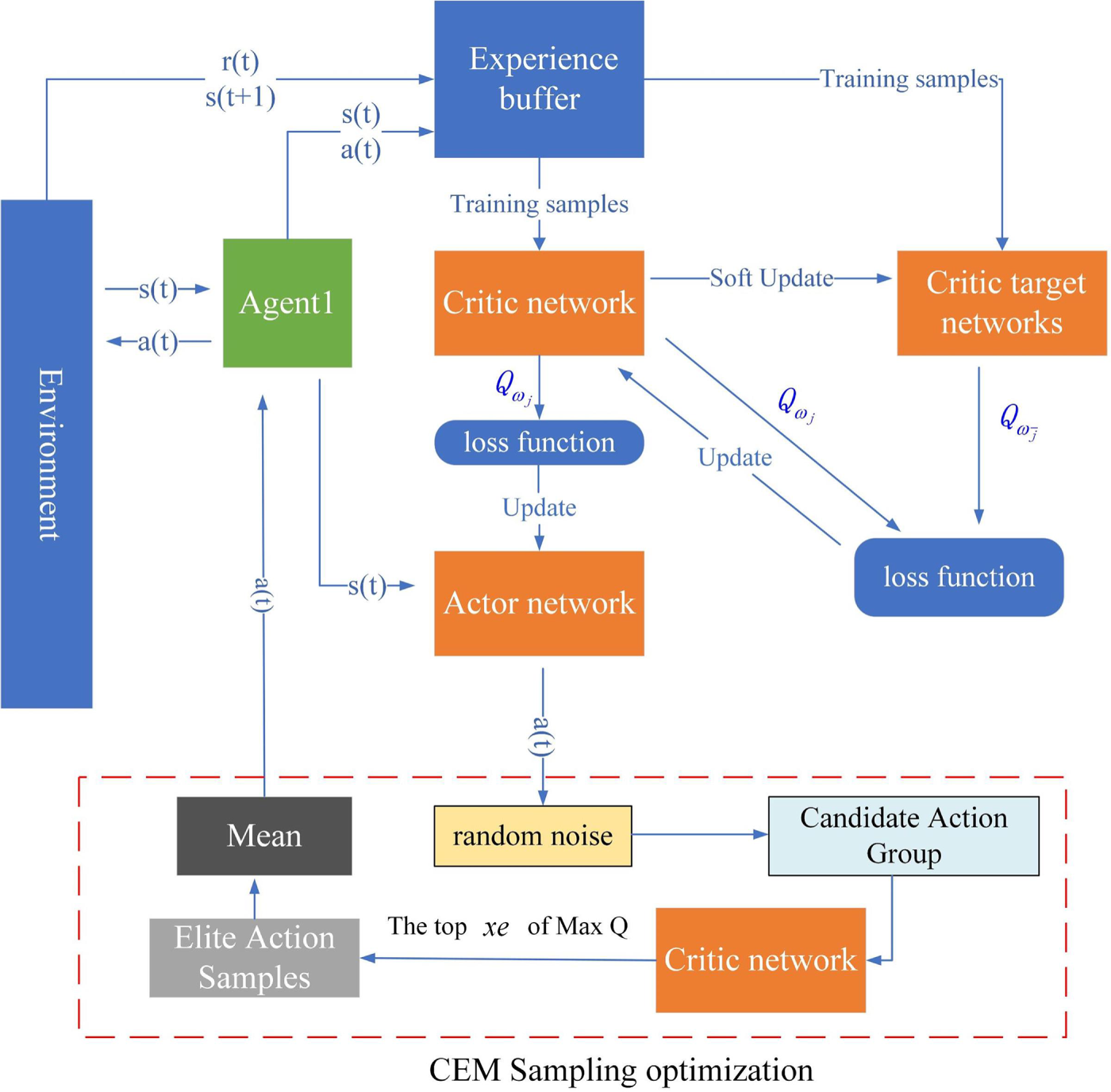
Figure 2: K-SAC algorithm framework.
Then calculate the loss function as follows:
The continuous nature of the algorithm’s action space requires the policy network to output the mean and standard deviation of a Gaussian distribution. A key issue is that action sampling based on this distribution is a non-differentiable operation. Thus, we employ a reparameterization trick to sample actions, which enables the use of the following loss function:
Update the current Actor network, finally update the target network as follows:
After updating all networks, the next action is obtained through the updated Actor network, and the above process is repeated until convergence or reaching the predetermined training steps to obtain the optimal target value and the current strategy.
The deep reinforcement learning algorithm is defined by the following fundamental elements: state, action, and reward. (1) State Space S: The environment state at time step
where
In this section, the performance of the proposed K-SAC algorithm is evaluated through comprehensive simulation and compared with different baseline schemes. To evaluate the efficiency of task offloading, we compare the performance of our proposed algorithm with DDPG [36], PPO [37], DDQN [38], and DQN [26] algorithms in terms of task volume and complexity.
The simulation experiments are conducted using Python 3.10. Following the parameters outlined in the reference literature [5,34], we establish a scenario in a
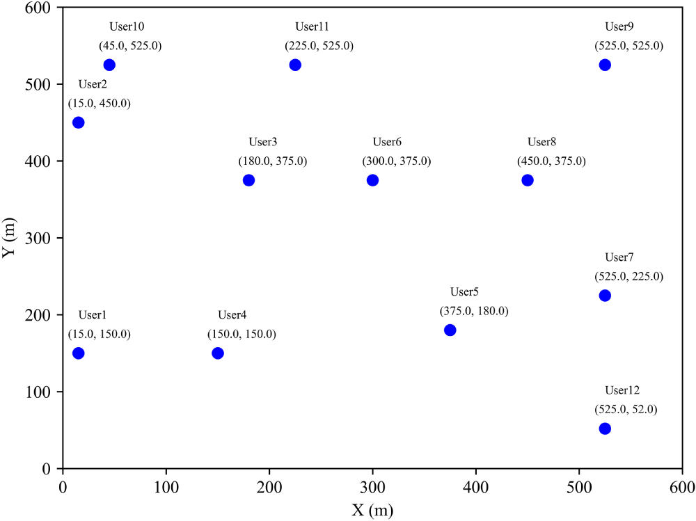
Figure 3: Simulation environment area map.
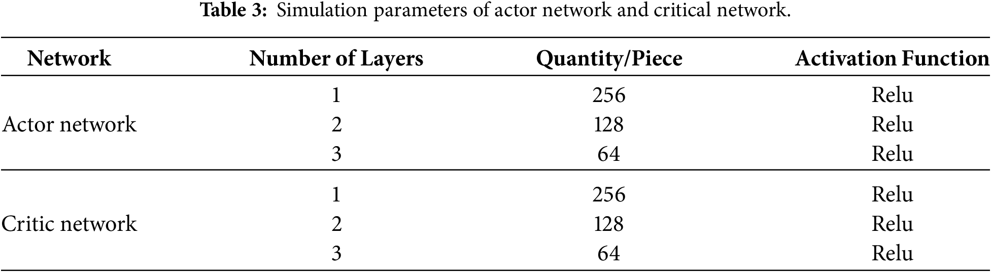
The K-SAC algorithm utilizes the rectified linear unit (ReLU) activation function for its Actor and Critic networks, whose parameters are specified in Table 3. Given that the two Critic networks share an identical architecture, their parameters are the same. The ReLU function was selected because it is computationally efficient and effectively mitigates the vanishing gradient problem by only propagating the maximum value.
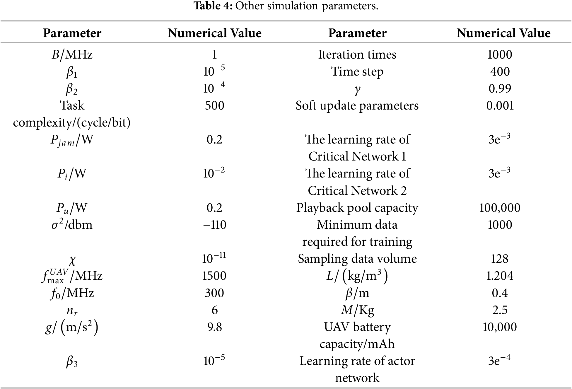
The remaining simulation parameters are shown in Table 4.
4.2 Analysis of Simulation Results
In this paper, the model environment considers that users move randomly. In order to provide users with a more secure communication environment, a ground jammer is added to further ensure security. Therefore, a K-SAC proposed scheme based on SAC is proposed. The algorithm first clusters the user’s location at a certain moment to obtain the optimal placement position of the ground jammer, forming the initial environment. Then, using the improved SAC algorithm, the optimal offloading strategy and auxiliary drone position corresponding to the optimal system benefits are obtained, and the user’s task calculation is completed with the lowest latency and energy consumption in a secure communication environment.
Figs. 4 and 5 present the clustering results under different scenarios. In Fig. 4, subfigures (a–c) illustrate the distribution of clustering centers when the number of clusters is set to 1, 2, and 3, respectively, showing how users are progressively partitioned into finer groups based on spatial proximity. Fig. 5 depicts the variation of a single clustering center after random user movement, where subfigures (a–c) correspond to different stages of user mobility, demonstrating the adaptive capability of the clustering approach to dynamic changes in user distribution. From Fig. 4, it can be seen that as the number of cluster centers increases, the algorithm can find the corresponding number of cluster centers, making the distance between the ground jammer and each user optimal. From Fig. 5, it can be seen that as the user moves randomly, the clustering center position of the algorithm changes accordingly, and an optimal ground jammer position can be found again to achieve the best distance between the ground jammer and each user. This enables the algorithm to find the optimal placement position even when facing the placement of multiple ground jammers and random user movements, resulting in robust performance.
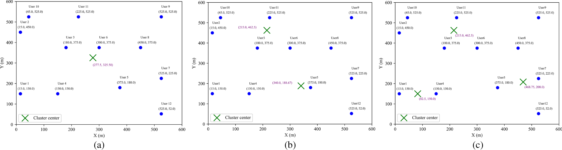
Figure 4: Multicenter clustering graph. (a) Single-center clustering; (b) Dual-center clustering; (c) Three-center clustering.
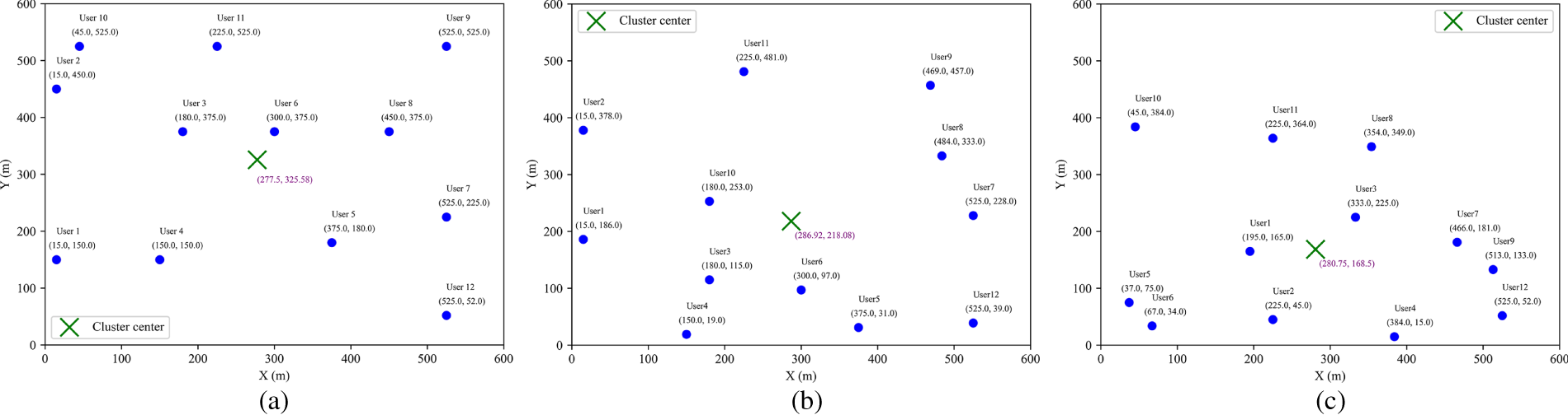
Figure 5: Multicenter clustering graph. (a) Single-center clustering (before user movement); (b) Single-center clustering (after user movement); (c) Single-center clustering (after user moves again).
Fig. 6 shows the user task offloading strategy corresponding to the maximum system benefit when the user task volume in the environment is 6 times the base task volume, the auxiliary drone transmission power is 0.4 w, and the task complexity is 1000 (cycles/bits). Fig. 7 shows the optimal hovering position of the auxiliary drone corresponding to the maximum system benefit. From Fig. 6, it can be observed that when the system efficiency is maximized, users 1 and 11 tend to offload to the base station for execution, while users 2, 6, and 8 tend to offload half to the base station and execute half locally. Users 3, 4, and 10 tend to balance local execution, offloading to base station execution, and offloading to auxiliary drone 1 execution. User 5 tends to balance local execution, offloading to base station execution, and offloading to auxiliary drone 2 execution. Users 7 and 9 tend to balance local execution, offloading to base station execution, offloading to auxiliary drone 1 execution, and offloading to auxiliary drone 2 execution. User 12 tends to unload half to auxiliary drone 2 and execute the other half locally. From Fig. 7, it can be observed that when the system efficiency is at its maximum, the optimal hovering point for auxiliary drone 1 is (10, 600), and the optimal hovering point for auxiliary drone 2 is (600, 10), located at the two diagonals of the ground jammer. These two positions have more users and are far away from invading drones.
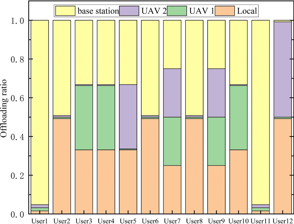
Figure 6: Optimal task offloading ratio of users.
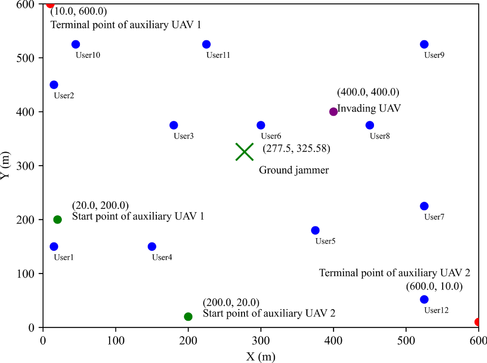
Figure 7: Optimal hovering positions of auxiliary UAVs.
Fig. 8 illustrates the impact of varying auxiliary drone transmission power on the system benefits achieved by different algorithms. The figure reveals a consistent downward trend in system efficiency for all tested algorithms as the drone’s transmission power is increased. This trend is primarily attributed to the fact that higher transmission power directly leads to greater transmission energy consumption by the auxiliary drones. While reducing task offloading might seem like a way to conserve energy, it paradoxically leads to longer task completion times. This extension contributes to a higher total of time delay and system energy consumption, ultimately degrading overall system efficiency. The K-SAC algorithm exhibits higher system efficiency under different auxiliary drone transmission powers, mainly due to its superior balancing ability in power control and task offloading decisions. Specifically, as the transmission power of the auxiliary drone increases, the weight of the energy consumption term in the system benefit function gradually increases. At this time, algorithms that rely solely on a single strategy update or single value evaluation (such as PPO, DDPG) are prone to over transmission or conservative offloading, leading to rapid accumulation of energy consumption or time delay. In contrast, K-SAC adopts a dual Critic structure and uses a candidate action evaluation mechanism to screen actions, enabling the strategy to more accurately evaluate the coupling effect between energy consumption and latency under high-power conditions during the update process, thereby avoiding extreme decisions and maintaining a relatively balanced offloading and power allocation strategy. Therefore, the data in Fig. 8 shows that over the transmission power range of 0.2 to 1, the K-SAC algorithm consistently outperforms the others. It maintains the highest average system efficiency, surpassing PPO by 4.92% and thus showcasing its good performance.
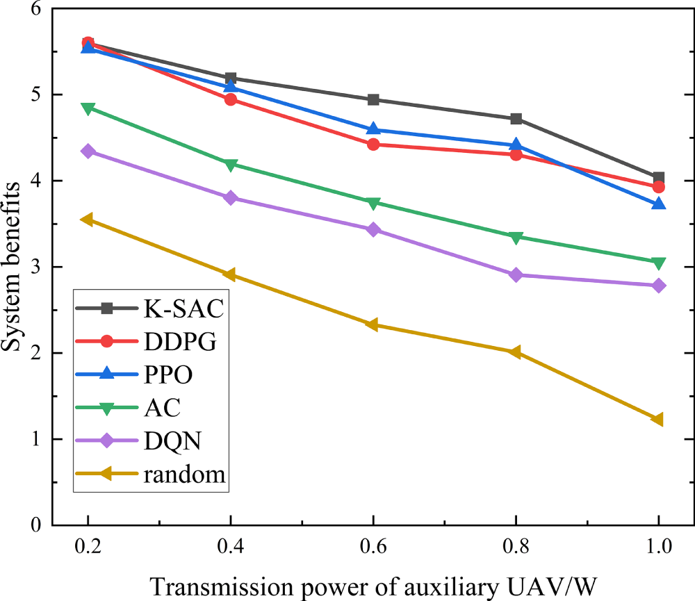
Figure 8: Changes in system benefits with the transmitted power of auxiliary UAV under different algorithms.
Fig. 9 is a simulation diagram of the system benefits under different algorithms as the interference power of auxiliary drones and ground jammers varies. From Fig. 9, it can be seen that the system efficiency of all algorithms decreases with the increase of interference power from auxiliary drones and ground jammers. This is mainly because as the interference power from auxiliary drones and ground jammers increases, the system’s interference energy consumption increases. While diminishing the amount of task offloading offers the benefits of shorter transmission times and lower interference energy, this strategy also extends the task completion time. This trade-off ultimately leads to a higher aggregate of time delay and system energy, which in turn degrades overall system efficiency. Furthermore, the performance curves tend to stabilize at high interference power levels. The reason is that high interference causes a substantial rise in the system’s energy consumption. To counteract this and maintain efficiency, users strategically reduce their offloading to auxiliary drones. This decision prolongs the task completion time but ultimately results in only a marginal change to the overall system efficiency, explaining the observed stability. Benefiting from its dual-critic structure, K-SAC adopts conservative value estimation to screen candidate actions, enabling more robust offloading decisions under strong interference compared with other algorithms. As a result, K-SAC is more effective in balancing interference energy consumption and task completion delay, leading to a 14.63% improvement in average system benefit when the jamming power increases from 0.1 to 0.5.
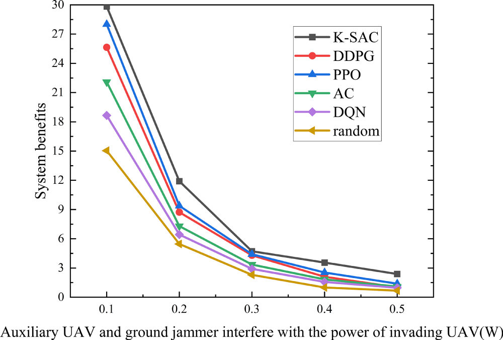
Figure 9: Variation of system benefit with jamming power of auxiliary UAV and ground jammer under different algorithms.
Fig. 10 is a simulation diagram of the system benefits varying with task complexity under different algorithms. Fig. 10 demonstrates a clear trend where the system efficiency of all evaluated algorithms declines as user task complexity grows. The primary reason for this is that more complex tasks necessitate longer computation times. While offloading tasks to auxiliary drones and base stations can shorten computation, this strategy concurrently increases transmission duration, transmission energy, and interference energy. This cumulative increase in both time delay and total energy consumption is what ultimately degrades system efficiency. In this scenario, PPO tends to favor aggressive task offloading to reduce local computation delay, which can significantly increase transmission and interference energy costs. In contrast, K-SAC will adopt a more robust offloading decision. Consequently, K-SAC consistently outperforms PPO when the task complexity increases from 800 to 1200, achieving a 13.67% higher average system benefit.
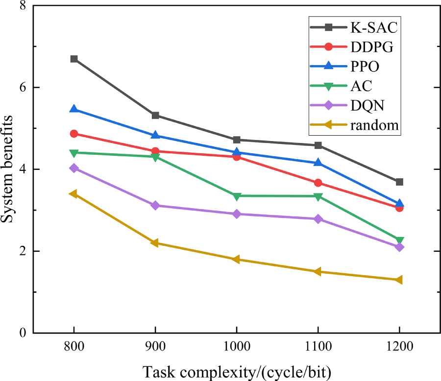
Figure 10: Changes in system benefits with task complexity under different algorithms.
Fig. 11 is a simulation diagram of system benefits varying with the size of user tasks under different algorithms. The results in Fig. 11 indicate a consistent decline in system efficiency for all algorithms as the user task size expands. The primary driver for this trend is the concurrent increase in both computation and transmission durations required for larger tasks. While offloading to auxiliary drones offers a way to shorten computation, it introduces a penalty in the form of higher transmission and interference energy consumption. This trade-off leads to a higher aggregate of time delay and system energy, thus diminishing overall efficiency. PPO, which updates policies based on local policy gradients, has limited capability to adapt its offloading strategy when task sizes vary significantly. By contrast, K-SAC evaluates multiple candidate actions at each decision step and selects the action with the highest estimated value, enabling it to dynamically adjust offloading ratios according to task scale. This enhanced decision flexibility allows K-SAC to effectively suppress excessive energy consumption under large task sizes, leading to a 9.83% improvement in average system benefit compared with PPO when the task size multiplier increases from 3 to 7.
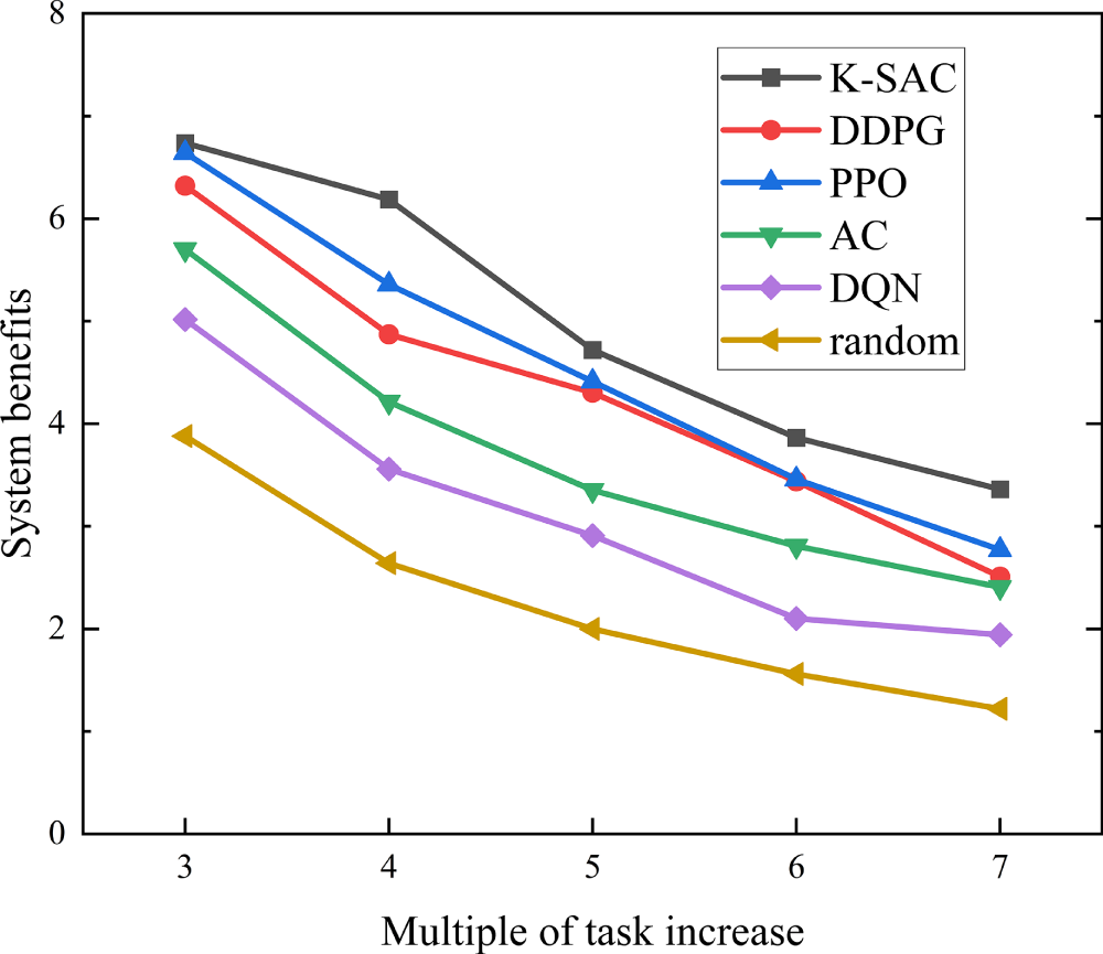
Figure 11: Changes in system benefits with user task size under different algorithms.
This paper aims at the problems of system time delay, energy consumption and UAV safe communication in the UAV aided edge computing system with random user movement. First, it constructs the MEC system model of UAV secure communication considering random user movement and adding ground jammers, and then proposes the task offloading scheme of K-SAC algorithm to solve the problem. The simulation results show that the proposed scheme has excellent performance and can reduce system time delay and energy consumption while ensuring communication security in the case of random user movement. Specifically, the algorithm achieves an average efficiency improvement of 9.83% under varying computational task sizes, 13.67% with different task complexities, and 14.63% against various interference powers, demonstrating its capacity to effectively enhance system performance.
However, this study relies on assumptions that may lead to optimistic performance estimates. Specifically, the model presumes precise knowledge of eavesdropper locations, which is challenging to acquire in complex real-world environments where adversaries may be hidden or mobile. In future work, we plan to address this challenge by investigating robust reinforcement learning frameworks that can operate effectively under location uncertainty.
Acknowledgement: Jiajia Liu, Fei Jia and Huibing Zhang acknowledge the support from the Guilin University of Electronic Technology. Shuchen Pang, Peng Xie, Haitao Zhou, Chenxi Du, Haoran Hu, Bo Tang and Jianhua Liu acknowledge the support from Civil Aviation Flight University of China.
Funding Statement: This research was supported by the Laibin City Scientific Research and Technology Development Program Project (No. 241509), Guangxi Key Research and Development Program(AB24010237).
Author Contributions: The individual author contributions are as follows. Jiajia Liu, Peng Xie and Huibing Zhang were responsible for the conceptualization, design, and initial drafting of the manuscript. Data collection, analysis, and interpretation were carried out by Shuchen Pang, Peng Xie, Jiajia Liu, Haitao Zhou, Chenxi Du, Bo Tang, Jianhua Liu, Haoran Hu, Fei Jia. All authors reviewed and approved the final version of the manuscript.
Availability of Data and Materials: The data that support the findings of this study are available from the Corresponding Author upon reasonable request.
Ethics Approval: Not applicable.
Conflicts of Interest: The authors declare no conflicts of interest.
References
1. Nguyen TH, Do VD, Le HL, Nguyen CL, Le DV, Niyato D. Deep reinforcement learning for multi-hop offloading in UAV-assisted edge computing. IEEE Trans Veh Technol. 2023;72(12):16917–22 doi:10.1109/tvt.2023.3292815. [Google Scholar] [CrossRef]
2. Liu J, Tang B, Liu J, Tu X. Dynamic region partitioning and joint optimization for STAR-RIS-assisted UAV edge computing systems via deep reinforcement learning. IEEE Wirel Commun Lett. 2025;15:505–9 doi:10.1109/lwc.2025.3629719. [Google Scholar] [CrossRef]
3. Akter S, Kim DY, Yoon S. Task offloading in multi-access edge computing enabled UAV-aided emergency response operations. IEEE Access. 2023;11:23167–88 doi:10.1109/access.2023.3252575. [Google Scholar] [CrossRef]
4. Kong X, Duan G, Hou M, Shen G, Wang H, Yan X. Deep reinforcement learning-based energy-efficient edge computing for internet of vehicles. IEEE Trans Ind Inform. 2022;18(9):6308–16 doi:10.1109/tii.2022.3155162. [Google Scholar] [CrossRef]
5. Acheampong A, Zhang Y, Xu X. A parallel computing based model for online binary computation offloading in mobile edge computing. Comput Commun. 2023;203:248–61 doi:10.1016/j.comcom.2023.03.004. [Google Scholar] [CrossRef]
6. Liu J, Xie P, Liu J, Tu X. Task offloading and trajectory optimization in UAV networks: a deep reinforcement learning method based on SAC and A-star. Comput Model Eng Sci. 2024;141(2):1243. [Google Scholar]
7. Shi Z, Wang L, Lin Y, Cai A, Fan J, Liu C. Dynamic offloading strategy in SAGIN-based emergency VEC: a multi-UAV clustering and collaborative computing approach. Veh Commun. 2025;55:100952. [Google Scholar]
8. Wang L, Zhou Q, Shen Y. Computation efficiency maximization for UAV-assisted relaying and MEC networks in urban environment. IEEE Trans Green Commun Netw. 2022;7(2):565–78 doi:10.1109/tgcn.2022.3222398. [Google Scholar] [CrossRef]
9. Xu Y, Zhang T, Yang D, Liu Y, Tao M. Joint resource and trajectory optimization for security in UAV-assisted MEC systems. IEEE Trans Commun. 2020;69(1):573–88 doi:10.1109/tcomm.2020.3025910. [Google Scholar] [CrossRef]
10. Islam MS, Mahmoud AS, Sheltami TR. AI-enhanced intrusion detection for UAV systems: a taxonomy and comparative review. Drones. 2025;9(10):682. [Google Scholar]
11. Xiao W, Li M, Alzahrani B, Alotaibi R, Barnawi A, Ai Q. A blockchain-based secure crowd monitoring system using UAV swarm. IEEE Netw. 2021;35(1):108–15 doi:10.1109/mnet.011.2000210. [Google Scholar] [CrossRef]
12. Ghribi E, Khoei TT, Gorji HT, Ranganathan P, Kaabouch N. A secure blockchain-based communication approach for UAV networks. In: Proceedings of the 2020 IEEE International Conference on Electro Information Technology (EIT); 2020 Jul 31–Aug 1; Chicago, IL, USA. p. 411–5. [Google Scholar]
13. Gai K, Wu Y, Zhu L, Choo KKR, Xiao B. Blockchain-enabled trustworthy group communications in UAV networks. IEEE Trans Intell Transp Syst. 2020;22(7):4118–30 doi:10.1109/tits.2020.3015862. [Google Scholar] [CrossRef]
14. Usman M, Amin R, Aldabbas H, Alouffi B. Lightweight challenge-response authentication in SDN-based UAVs using elliptic curve cryptography. Electronics. 2022;11(7):1026 doi:10.3390/electronics11071026. [Google Scholar] [CrossRef]
15. Devi P, Bharti MR, Gautam D. A survey on physical layer security for 5G/6G communications over different fading channels: approaches, challenges, and future directions. Veh Commun. 2025;53:100891 doi:10.1016/j.vehcom.2025.100891. [Google Scholar] [CrossRef]
16. Cheng Q, Zhou Y, Liu H, Yang L, Ma Z, Fan P. Physical layer authentication in UAV communications with channel randomness and Jamming Uncertainty. IEEE Trans Veh Technol. 2025;74(6):9894–8 doi:10.1109/tvt.2025.3532982. [Google Scholar] [CrossRef]
17. Zhou Y, Pan C, Yeoh PL, Wang K, Elkashlan M, Vucetic B. Secure communications for UAV-enabled mobile edge computing systems. IEEE Trans Commun. 2020;68(1):376–88 doi:10.1109/tcomm.2019.2947921. [Google Scholar] [CrossRef]
18. Lu W, Ding Y, Gao Y, Chen Y, Zhao N, Ding Z. Secure NOMA-based UAV-MEC network towards a flying eavesdropper. IEEE Trans Commun. 2022;70(5):3364–76 doi:10.1109/tcomm.2022.3159703. [Google Scholar] [CrossRef]
19. Zhang Y, Kuang Z, Feng Y, Hou F. Task offloading and trajectory optimization for secure communications in dynamic user Multi-UAV MEC systems. IEEE Trans Mob Comput. 2024;23(12):14427–40 doi:10.1109/tmc.2024.3442909. [Google Scholar] [CrossRef]
20. He Y, Xiang K, Cao X, Guizani M. Task scheduling and trajectory optimization based on fairness and communication security for multi-UAV-MEC system. IEEE Internet Things J. 2024;11(19):30510–23 doi:10.1109/jiot.2024.3412825. [Google Scholar] [CrossRef]
21. Miao J, Chen H, Li H, Bai S. Secrecy energy efficiency enhancement in UAV-assisted MEC system. Sensors. 2023;23(2):723 doi:10.3390/s23020723. [Google Scholar] [PubMed] [CrossRef]
22. Lu F, Liu G, Lu W, Gao Y, Cao J. Resource and trajectory optimization for UAV-relay-assisted secure maritime MEC. IEEE Trans Commun. 2023;72(3):1641–52 doi:10.1109/tcomm.2023.3330884. [Google Scholar] [CrossRef]
23. Zhong L, Liu Y, Deng X, Wu C, Liu S, Yang LT. Distributed optimization of multi-role UAV functionality switching and trajectory for security task offloading in UAV-assisted MEC. IEEE Trans Veh Technol. 2024;73(12):19432–47 doi:10.1109/tvt.2024.3434354. [Google Scholar] [CrossRef]
24. Ding Y, Feng Y, Lu W, Zheng S, Zhao N, Meng L. Deep reinforcement learning-based trajectory optimization and resource allocation for secure UAV-enabled MEC networks. In: Proceedings of the IEEE INFOCOM 2024—IEEE Conference on Computer Communications Workshops (INFOCOM WKSHPS); 2024 May 20–24; Vancouver, BC, Canada. p. 01–5. [Google Scholar]
25. Hu H, Hao S, Wang Q, Zhu C, Peng F, Zhou F. Robust trajectory and task allocation in secure UAV-assisted MEC system with cooperative jamming. In: Proceedings of the 2023 IEEE 23rd International Conference on Communication Technology (ICCT); 2023 Oct 20–22; Wuxi, China. p. 1342–7. [Google Scholar]
26. Lei H, Yang M, Jiang J, Park KH, Pan G. Secure offloading in NOMA-aided aerial MEC systems based on deep reinforcement learning. IEEE J Miniaturization Air Space Syst. 2025;6(2):113–24 doi:10.1109/jmass.2024.3479456. [Google Scholar] [CrossRef]
27. Lu W, Ding Y, Gao Y, Hu S, Wu Y, Zhao N. Resource and trajectory optimization for secure communications in dual unmanned aerial vehicle mobile edge computing systems. IEEE Trans Ind Inform. 2021;18(4):2704–13 doi:10.1109/tii.2021.3087726. [Google Scholar] [CrossRef]
28. Ding Y, Feng Y, Lu W, Zheng S, Zhao N, Meng L. Online edge learning offloading and resource management for UAV-assisted MEC secure communications. IEEE J Sel Top Signal Process. 2022;17(1):54–65 doi:10.1109/jstsp.2022.3222910. [Google Scholar] [CrossRef]
29. Wei X, Cai L, Wei N, Zou P, Zhang J, Subramaniam S. Joint UAV trajectory planning, DAG task scheduling, and service function deployment based on DRL in UAV-empowered edge computing. IEEE Internet Things J. 2023;10(14):12826–38 doi:10.1109/jiot.2023.3257291. [Google Scholar] [CrossRef]
30. Wang Y, Sheng M, Wang X, Wang L, Li J. Mobile-edge computing: partial computation offloading using dynamic voltage scaling. IEEE Trans Commun. 2016;64(10):4268–82. [Google Scholar]
31. Wang M, Shi S, Gu S, Gu X, Qin X. Q-learning based computation offloading for multi-UAV-enabled cloud-edge computing networks. IET Commun. 2020;14(15):2481–90. [Google Scholar]
32. Bjerkebæk I, Toftaker H. Reliability assessment combining importance resampling and the cross entropy method. Electr Power Syst Res. 2024;234:110722 doi:10.1016/j.epsr.2024.110722. [Google Scholar] [CrossRef]
33. Nguyen HT, Tran K, Luong NH. Combining soft-actor critic with cross-entropy method for policy search in continuous control. In: Proceedings of the 2022 IEEE Congress on Evolutionary Computation (CEC); 2022 Jul 18–23; Padua, Italy. p. 1–8. [Google Scholar]
34. Ahmed M, Seraj R, Islam SMS. The k-means algorithm: a comprehensive survey and performance evaluation. Electronics. 2020;9(8):1295. [Google Scholar]
35. Ay M, Özbakır L, Kulluk S, Gülmez B, Öztürk G, Özer S. FC-Kmeans: fixed-centered K-means algorithm. Expert Syst Appl. 2023;211:118656. [Google Scholar]
36. Kumar AS, Zhao L, Fernando X. Task Offloading and resource allocation in vehicular networks: a lyapunov-based deep reinforcement learning approach. IEEE Trans Veh Technol. 2023;72(10):13360–73 doi:10.1109/tvt.2023.3271613. [Google Scholar] [CrossRef]
37. Yang S, Liu J, Zhang F, Li F, Chen X, Fu X. Caching-enabled computation offloading in multi-region MEC network via deep reinforcement learning. IEEE Int Things J. 2022;9(21):21086–98 doi:10.1109/jiot.2022.3176289. [Google Scholar] [CrossRef]
38. Peng Y, Liu Y, Li D, Zhang H. Deep reinforcement learning based freshness-aware path planning for UAV-assisted edge computing networks with device mobility. Remote Sens. 2022;14(16):4016–24. doi:10.3390/rs14164016. [Google Scholar] [CrossRef]
Cite This Article
 Copyright © 2026 The Author(s). Published by Tech Science Press.
This work is licensed under a Creative Commons Attribution 4.0 International License , which permits unrestricted use, distribution, and reproduction in any medium, provided the original work is properly cited.
 Downloads
 Citation Tools