
 Submit a Paper
 Propose a Special lssue
 Open Access
ARTICLE

Artificial Neural Network-Based Prediction and Validation of Drill Flank Wear in GFRP Machining for Sustainable and Smart Manufacturing
Manipal Institute of Technology, Manipal Academy of Higher Education, Manipal, India
* Corresponding Author: Manjunath Shettar. Email:
(This article belongs to the Special Issue: Advanced Computational Modeling and Simulations for Engineering Structures and Multifunctional Materials: Bridging Theory and Practice)
Computers, Materials & Continua 2026, 87(3), 33 https://doi.org/10.32604/cmc.2026.078574
Received 04 January 2026; Accepted 12 February 2026; Issue published 09 April 2026
 View Full Text
 Download PDF
Abstract
Glass fiber-reinforced polymer composites (GFRPCs) are extensively utilized in the aerospace, automotive, and structural sectors; nevertheless, their heterogeneous and abrasive characteristics result in rapid tool wear during drilling. Drill flank wear among various wear mechanisms notably influences hole quality and dimensional accuracy. This research investigates the impact of spindle speed, feed rate, and drill diameter on flank wear during dry drilling of GFRPC laminates with high-speed steel (HSS) twist drills. A full-factorial design with 81 experiments is used to create a comprehensive dataset. ANOVA indicates that spindle speed is the dominant factor affecting wear changes, accounting for 74.43%, followed by feed rate (15.80%) and drill diameter (6.16%). A linear regression model demonstrates reasonable statistical sufficiency (R2 = 0.964), but it falls short in reflecting nonlinear interactions. Hence, an artificial neural network (ANN) model is developed to improve prediction. The multilayer feed-forward ANN with a 3-10-6-1 architecture, trained using the Levenberg–Marquardt optimization algorithm, achieves excellent predictive accuracy, with high correlation and low root-mean-square error. Model validation was achieved through independent confirmation experiments, yielding a mean absolute percentage error of only 2.27%, with all predictions falling within the permissible wear range. The findings indicate that ANN-based modeling provides a reliable framework for capturing the complex nonlinear relationships governing tool wear in GFRPC drilling and serves as a viable soft sensor for tool condition monitoring, process optimization, and sustainable, data-driven manufacturing.Keywords
Glass fiber-reinforced polymer composites have become vital in modern engineering applications due to their high specific strength, dimensional stability, and excellent corrosion and fatigue resistance [1,2]. Consequently, GFRPCs are being increasingly used in components such as aerospace structures, automotive panels, marine assemblies, and sporting goods, as well as in a wide range of structural and semi-structural products [3–5]. This growing trend toward GFRPC laminates has increased demand for precise, reliable machining operations, particularly drilling [6]. Drilled holes represent the primary features for mechanical fastening, and even slight deviations in dimensional accuracy can compromise assembly integrity, load transfer, and long-term performance [7].
However, GFRPC machining problems persist owing to the composite’s heterogeneous and highly abrasive nature. The combination of hard glass fibers and thermoset matrix often results in rapid tool wear, fiber pull-out, delamination, thermal softening, and surface degradation [8–10]. Among the aforementioned issues, flank wear on the drill tool is significant because it directly affects hole quality and the dimensional accuracy of fastener locations. Several studies have demonstrated that drilling parameters, such as spindle speed, feed rate, and drill diameter, have a significant impact on the extent of tool wear [11–13]. In this context, the optimization and prediction of tool wear have emerged as critical issues in composite machining research.
Traditional modeling techniques have commonly relied on regression-based statistical approaches to establish relationships between machining parameters and tool wear [13,14]. While these methods provide valuable insights into tool wear modeling, their predictive capability is often limited in the presence of complex nonlinear interactions among machining variables. In recent years, artificial neural networks (ANNs) have emerged as a powerful alternative for modeling machining behavior owing to their ability to learn complex, nonlinear relationships from experimental data [15–17]. Several studies have successfully employed ANN frameworks to predict surface roughness, cutting forces, delamination, and other machining responses related to fiber-reinforced composites [18,19]. Zhu et al. [20] developed a BP-ANN model using multi-sensor signals (thrust force and vibration) and showed that ANN can accurately correlate extracted signal features with flank wear, achieving prediction accuracies up to 87%. Their work highlights that ANN-based models, combined with signal processing techniques, are reliable tools for real-time monitoring and prediction of tool wear in CFRP drilling operations. Hu et al. [21] proposed a BP neural network optimized using an improved Grey Wolf algorithm to predict flank wear during GFRP drilling, using thrust force, vibration amplitude, cutting speed, feed rate, and number of holes as inputs, achieving significantly reduced prediction error. Their results confirm that ANN-based models can accurately capture the nonlinear relationship between machining signals and tool flank wear.
However, ANN-based prediction and validation of flank wear during drilling GFRPC laminates using HSS twist drills have received limited attention, despite the widespread industrial use of HSS tools due to their low cost and easy availability. The present study addresses this gap by systematically investigating the effects of key drilling parameters on flank wear during machining of GFRPC laminates and by developing robust ANN models that accurately predict tool wear. To ensure comprehensive coverage of the range defined by the drilling parameters, a full factorial experimental design is employed. Several ANN training algorithms and network configurations are evaluated to select the most efficient model for a given prediction. Furthermore, independent testing and validation experiments are conducted to assess the reliability and generalization capability of the optimized ANN framework.
2.1 Material Preparation and Laminate Fabrication
GFRPC laminates are fabricated using a controlled hand lay-up method to ensure specimen uniformity, repeatability, and mechanical stability during drilling experiments. An isophthalic polyester resin is employed as the matrix material, while E-glass fiber mats are used as the reinforcing phase. Throughout the fabrication process, a resin-to-fiber weight ratio of 1:3 is maintained to achieve the best balance between strength, stiffness, and machining performance.
The process begins with thorough cleaning of the mould surface, followed by the application of a releasing agent to prevent adhesion during laminate removal. Pre-cut E-glass fiber mats are systematically laid on the mould, maintaining fiber orientation to minimize mechanical variation between samples. The resin, previously mixed with the required quantities of hardener and accelerator, is uniformly applied by brushes and rollers. Entrapped air is subsequently removed using a hand roller, thereby enhancing laminate consolidation and minimizing defect formation.
These laminates are initially cured at ambient temperature for several hours, followed by post-curing to further enhance their mechanical integrity. After complete curing, the laminates are cut into standardized rectangular test specimens suitable for drilling experiments, each having a uniform final thickness of 10 mm. Such a controlled fabrication sequence ensures consistent structural and mechanical characteristics across all specimens, thereby reducing experimental variability during the evaluation of drill flank wear.
2.2 Drilling Experiments and Measurement of Flank Wear
The experiments are conducted on a CNC Vertical Machining Centre (VMC) to ensure precise control of the drilling parameters. The GFRPC laminates are clamped rigidly to suppress vibrational effects and prevent unintended movement during drilling. All the trials are conducted under dry machining conditions. Generally, coolants are not used during industrial composite drilling to prevent swelling or delamination of the laminate [22].
To ensure accurate and unbiased assessment of tool wear, each experimental run is performed using a new HSS twist drill. In a full factorial design, the machining parameters for each drilling configuration are specified as spindle speed, feed rate, and drill diameter. Subsequently, each test specimen is drilled with 80 holes according to a predefined pattern to ensure sufficient flank wear progression without hazardous tool failure. Fig. 1 illustrates the drilled-hole pattern and spacing requirements for fastener joints in the GFRPC laminate.

Figure 1: GFRPC laminate with drilled holes.
Tool wear is quantified as the average flank wear land width, a widely accepted standard indicator of tool wear in drilling operations. Flank wear measurements are carried out using a toolmaker’s microscope by observing the wear land formed on the flank face near the cutting edge. Each drill is examined before and after drilling 80 holes under a given parameter combination. The difference between the initial and final measurements of the flank wear land width is recorded as the wear value in millimeters. This approach provides a consistent and reliable representation of wear progression during GFRPC drilling.
A fresh GFRPC laminate is used for each experimental combination to maintain uniformity across trials. The same operator performs all measurements, and the experiments are conducted under identical environmental conditions of temperature and humidity to minimize variability. The recorded flank wear values are used as the main response variable for ANN modeling and validation.
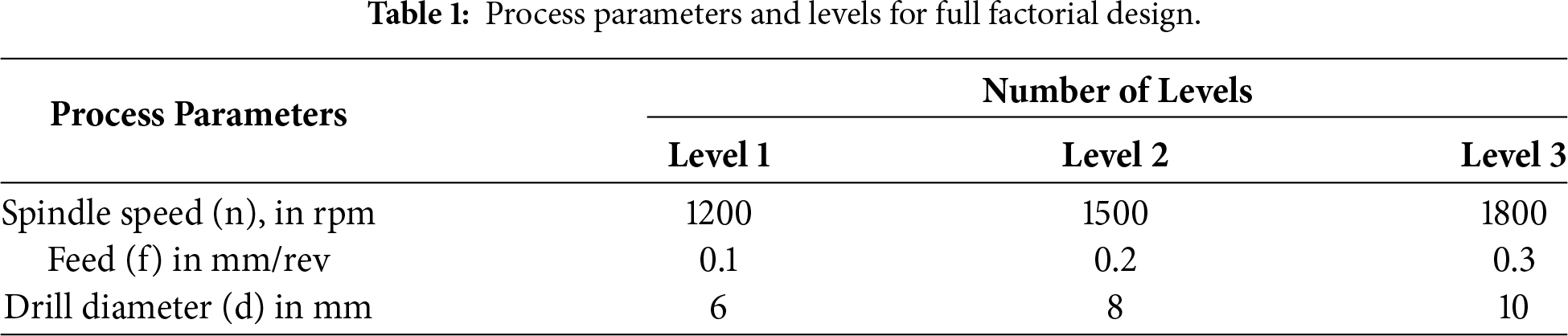
A full factorial design is employed to systematically investigate the influence of drilling parameters on tool flank wear. The selected parameters are based on results from other studies on composite drilling and include spindle speed, feed rate, and drill diameter. Each parameter is investigated at three distinct levels, as summarized in Table 1.
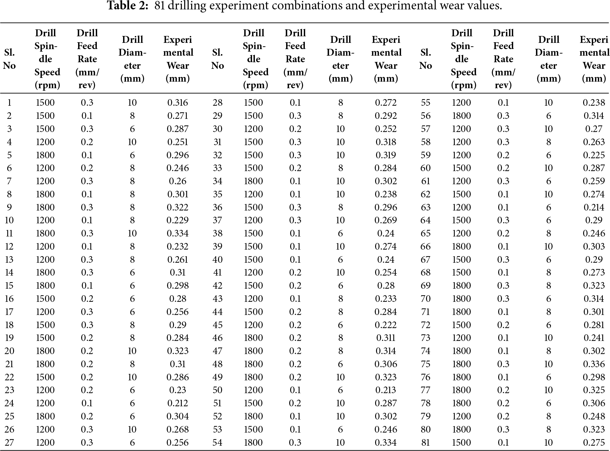
The full factorial design results in a total of 27 unique parameter combinations (3 × 3 × 3). Each unique combination is replicated three times, yielding a total of 81 drilling experiments. Replication is incorporated to account for the inherent experimental variability and enhance the robustness of statistical analyses and ANN predictions. All specimens are drilled using an identical standardized hole pattern commonly adopted for fastener joint preparation. Maintaining a consistent hole pattern ensures uniform heat generation and material removal rates across trials, ensuring uniform drilling conditions. As presented in Table 2, this dataset provides a solid foundation for training, testing, and validation of ANN models across a wide range of machining conditions.
Although only three machining parameters, viz., spindle speed, feed rate, and drill diameter, are investigated, the use of ANOVA is justified by the full factorial design with three levels per factor and multiple replications, yielding 81 experimental observations. ANOVA is employed in this study to systematically quantify the individual contribution and statistical significance of each drilling parameter on flank wear, rather than to increase model complexity. This analysis provides an interpretable baseline for understanding dominant wear mechanisms and serves as a precursor to the ANN-based modeling, which subsequently captures nonlinear interactions beyond the scope of linear regression.
The ANOVA results in Table 3 indicate that the constructed regression model is statistically significant, with an F-value of 686.59 and a p-value well below 0.001. These facts collectively suggest that the selected process parameters had a strong, significant influence on tool wear.
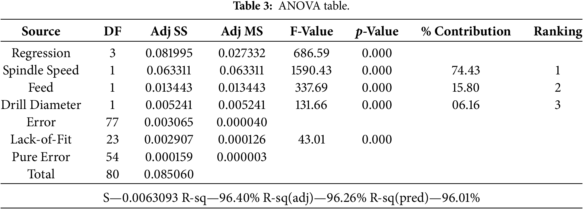
Considering only individual factors, spindle speed is identified as the most influential parameter, accounting for 74.43% of the total variation in flank wear. The extremely high F-value (1590.43) indicates that changes in spindle speed result in a significant alteration in the thermal and tribological conditions at the tool-workpiece interface. For example, at higher speeds, the increased frictional heating from the matrix’s action accelerates its softening, and the abrasive interaction between the glass fibers and the cutting edge intensifies, resulting in rapid wear.
The feed rate is the second most influential factor, accounting for 15.80% of the total variation. By increasing the feed rate, the material removal rate per revolution is raised; therefore, the thrust force and the contact stress on the flank face are also increased. The intensification of mechanical loading on the flank face further develops the micro-chipping and abrasive wear mechanisms along the cutting edge.
Wear variation due to changes in drill diameter is 6.16%, the least of the three parameters. However, its effect is still statistically significant (p < 0.001). A larger drill diameter increases the effective cutting length and contact area, thus slightly increasing the frictional forces and wear.
The regression model exhibits very good goodness-of-fit features, with R2 = 0.964, adjusted R2 = 0.9626, and predicted R2 = 0.9601. The close match between these values indicates high model stability and strong predictive ability. The low standard error (S = 0.0063093 mm) further indicates minimal deviation between the experimental and predicted responses. Even though the lack of fit is statistically significant, such behavior is characteristic of highly nonlinear composite machining processes; therefore, ANN-based modeling is more appropriate for capturing these complex relationships.
The linear regression model developed to relate the drilling parameters to flank wear is expressed as:
Tool wear = 0.03730 + 0.00011414 × Spindle speed + 0.15778 × Feed + 0.004926 × Drill diameter.
This equation provides a numerical explanation of how flank wear responds to changes in each machining variable. The positive coefficients for all parameters suggest that flank wear increases monotonically with increases in spindle speed, feed rate, and drill diameter.
The coefficient related to spindle speed indicates that it is the primary factor, with even moderate increases in rotational speed causing wear to rise significantly due to enhanced thermal softening of the matrix and intensified fiber-tool abrasion. The feed coefficient is quite large, supporting the idea that mechanical loading and chip thickness are the primary factors driving accelerated wear. The drill diameter coefficient is smaller; however, its cumulative effect at higher diameters becomes significant due to the more prolonged contact with the tool material.
Although the regression model successfully depicts the general trends, its linear nature limits its ability to fully explain the complex, nonlinear interactions inherent in composite drilling; therefore, the use of ANN models is explored in the following sections.
Residual plots (Fig. 2) are examined to assess the adequacy of the regression model and to verify whether the assumptions of normality, independence, and constant variance are met. The normal probability plot of residuals indicates that the data points are very close to a straight line, indicating that the residuals are approximately normally distributed.
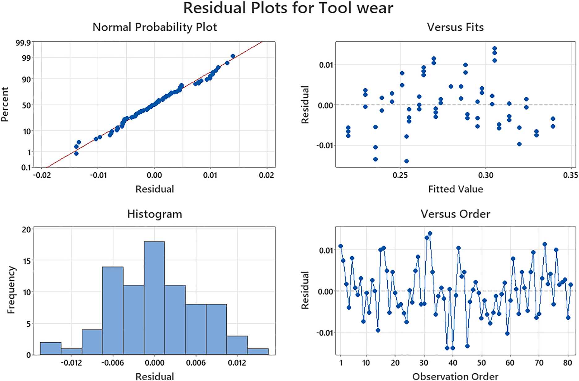
Figure 2: Residual plots for tool wear.
The residuals vs. fitted values graph shows random scatter without a discernible pattern or funnel shape, confirming homoscedasticity and the absence of systematic error. In other words, the regression model is not characterized by instability in variance across the prediction range.
Moreover, the residuals vs. order plot does not exhibit a trend or cycle, indicating that the experimental runs are independent and that there are no time-dependent effects, such as tool instability or environmental drift. Collectively, these plots provide evidence that the regression analysis is statistically valid and suitable for a preliminary interpretation of the effects of drilling parameters.
The main effects plot (Fig. 3) displays the isolated impact of each drilling parameter on flank wear by averaging out the effects of other factors. For spindle speed, a very steep positive slope is observed, again confirming its primary role in wear progression. The reason for the drastic increase in wear at higher speeds is the higher cutting temperatures and intensified abrasive interactions with glass fibers.
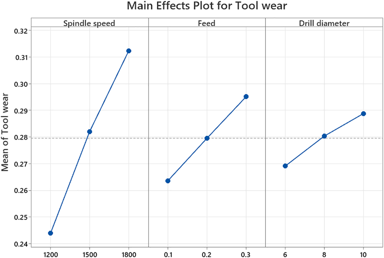
Figure 3: Main effects plots for tool wear.
The feed rate also reveals a noticeable upward trend, indicating that higher feeds lead to wear twice as fast due to increased thrust forces and mechanical stresses on the cutting edge. The slope related to feed changes is not as steep as that for spindle speed, but it is still considerable.
The main effects plot for drill diameter has a relatively gentle slope; thus, the influence is weaker but still positive on wear. Larger diameters extend the cutting-edge engagement and frictional contact, thereby gradually increasing wear.
In general, the main effects plot is in agreement with the ANOVA ranking, which is spindle speed > feed rate > drill diameter.
Interaction plots (Fig. 4) are examined to determine whether the impact of one parameter changes based on the level of another. The interaction between spindle speed and feed rate reveals significant non-parallel lines, indicating a strong interaction effect. At higher speeds, the effect of the feed rate on wear becomes highly significant, indicating a synergistic effect between thermal and mechanical wear.
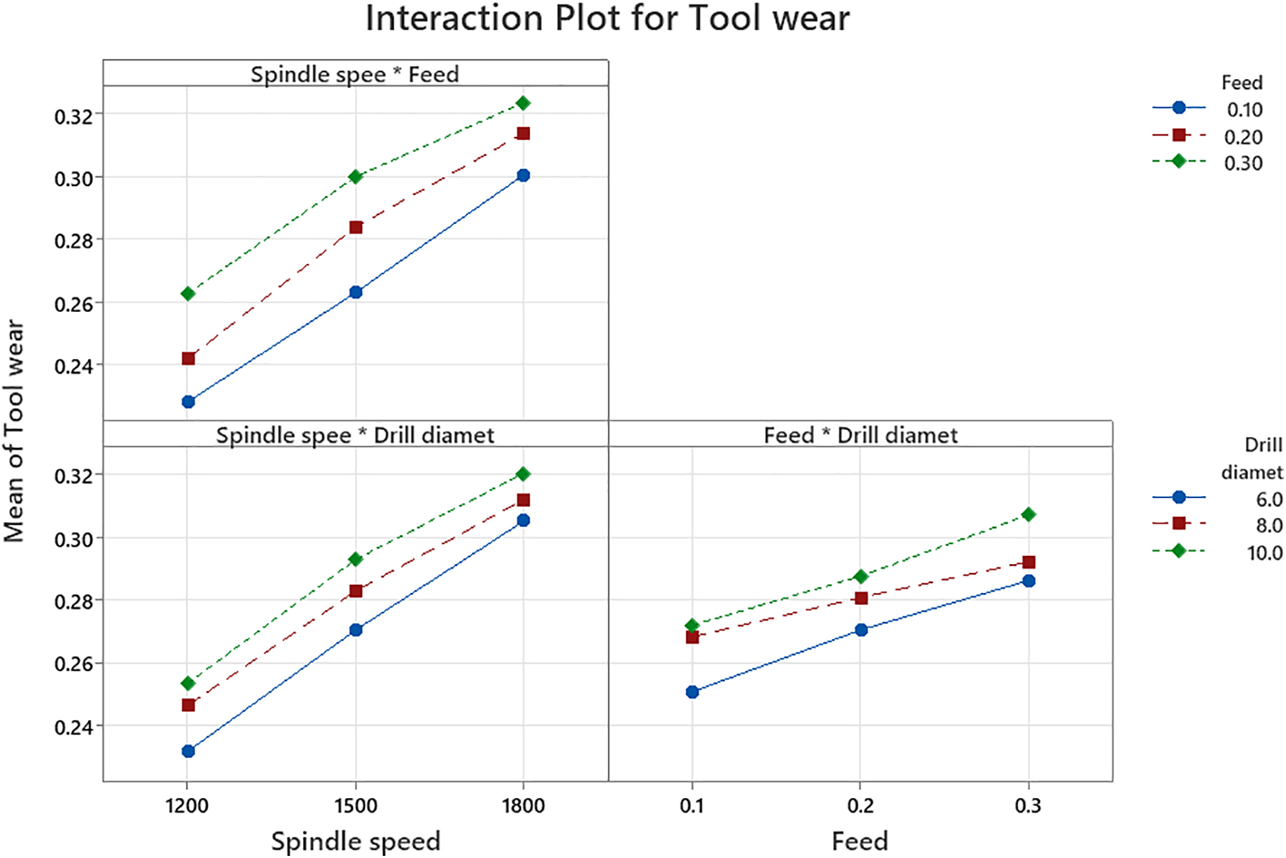
Figure 4: Interaction plot for tool wear.
On the other hand, the interaction between spindle speed and drill diameter shows a moderate effect. Larger diameters exaggerate the impact of high speeds because more heat is generated over a longer cutting edge.
The interaction between feed rate and drill diameter is relatively weak, as indicated by the almost parallel lines. It implies that their combined influence on flank wear is primarily additive, i.e., the factors are working independently.
These interaction trends reveal the intricacies of the wear mechanisms during GFRPC drilling and highlight the limitations of linear regression in characterizing such coupled nonlinear effects, thereby providing a rationale for the next section’s transition to ANN-based modeling.
4 ANN-Based Modeling of Flank Wear
Tool wear behaviour in composite machining involves complex, highly nonlinear interactions among machining parameters. Such complexities make classical regression modeling inadequate for accurate prediction. Therefore, an ANN approach is adopted in the present study to develop a soft computational modeling capable of predicting flank wear from fundamental process variables. This allows intelligent decision-making for tool replacement and ensures consistent machining of GFRPCs.
4.1 ANN Architecture and Functional Mechanisms
A multilayer, supervised, feed-forward ANN is designed in MATLAB R2024a to capture the complex, nonlinear relationship between drilling parameters and resulting tool wear. The model takes three machining inputs, viz., spindle speed (rpm), feed rate (mm/rev), and drill diameter (mm), each represented by one neuron in the input layer. These variables influence the thermomechanical load during drilling, thereby directly affecting flank wear development.
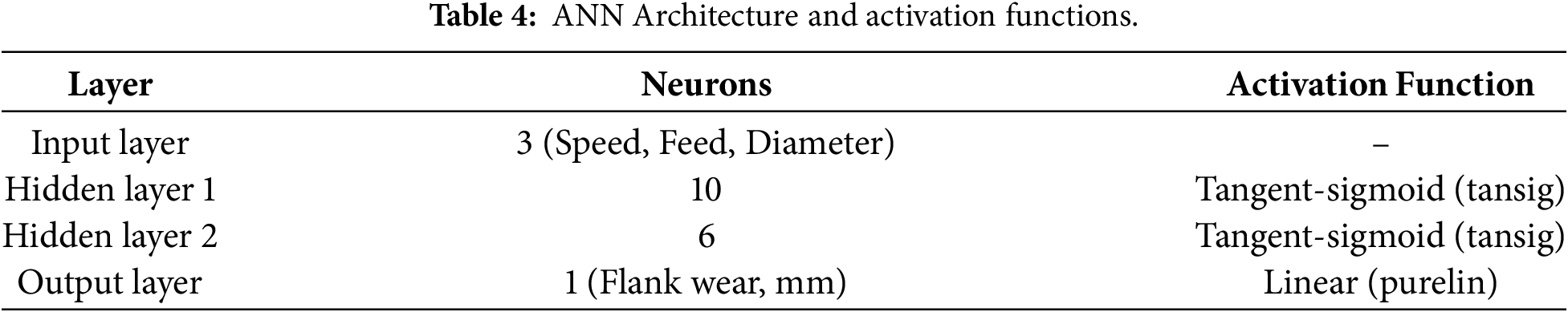
To more effectively capture the complex interactions among the drilling parameters, an ANN with two hidden layers is employed. The first layer has ten neurons, and the second one has six neurons. The network architecture 3-10-6-1 is considered the best among all the tested configurations. Each layer of the network uses a tangent-sigmoid activation function, which provides the necessary nonlinearity for modeling complex wear patterns. The output layer consists of a single neuron with a linear activation function; thus, flank wear can be directly predicted. In general, the hidden layers learn the underlying wear behavior while the linear output layer ensures the prediction remains physically interpretable. Table 4 shows the ANN Architecture and activation functions.
4.2 Network Training Methodology
The ANN is trained through supervised learning by comparing the predicted flank wear values with experimentally measured values. This training process continues until the prediction error is sufficiently reduced. The LM backpropagation algorithm has been used because it offers faster convergence and more stable learning than standard gradient-descent methods [23,24], which is particularly important for machining applications, as nonlinear responses are often observed in such operations.
The dataset of 81 drilling experiments is divided into 70% for training, 15% for validation, and 15% for testing. Training automatically stops when the validation loss stops improving, thereby avoiding overfitting. Training state plot in Fig. 5 showing the evolution of the gradient, μ (Mu), and validation checks during ANN learning. The gradient shows a rapid decrease and reaches the minimum acceptance level by the 7th epoch, confirming convergence of the weight updates. At the same time, the damping parameter μ tends to a smaller value, showing that the LM algorithm is more confident in the error surface. The validation checks are kept at a very low level relative to the maximum tolerance throughout the process; thus, the stopping criterion for the training stage is set appropriately before overfitting occurs. The trends, on the whole, align with the ANN model’s stable optimization and strong generalization capabilities. Here, the study has been completed in 7 epochs, further demonstrating the LM algorithm’s efficiency. The learning process depicted in Fig. 6 is consistent with the error consistently decreasing.
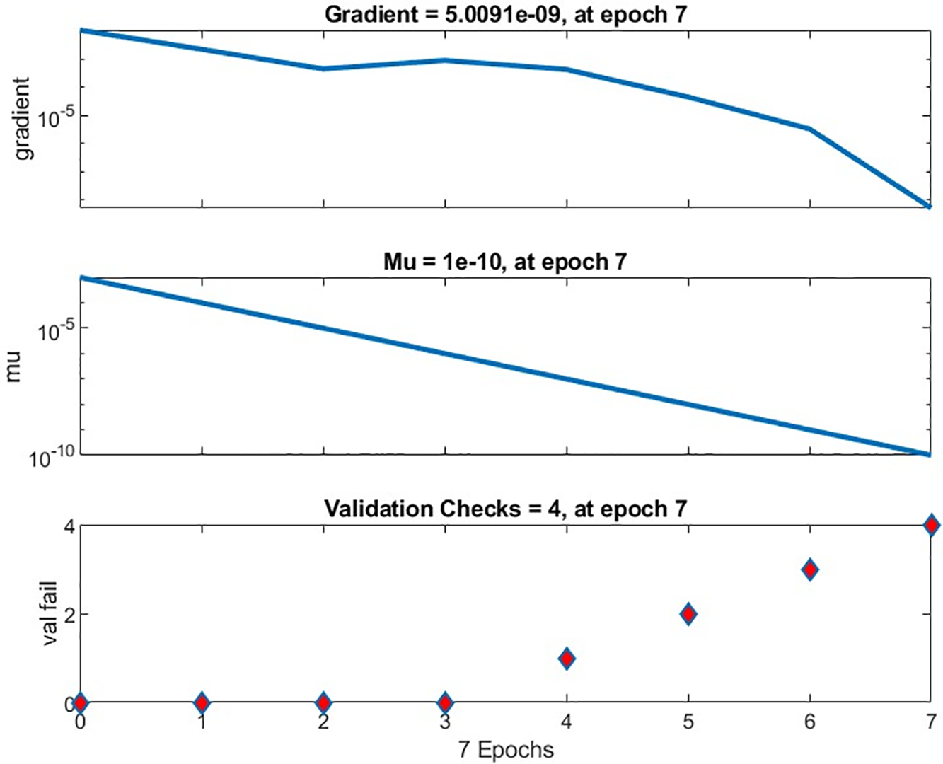
Figure 5: Training state plot-evolution of the gradient, Mu, and validation failure.
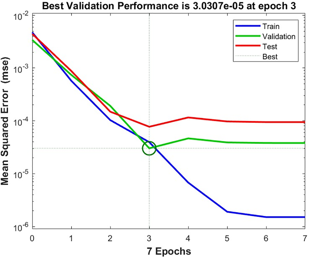
Figure 6: Training performance of ANN.
4.3 Prediction Performance of the ANN
The model’s predictive accuracy is evaluated by comparing predicted and actual flank wear values across training, validation, and test datasets, and across the overall dataset. As shown in Fig. 7, the points cluster closely around the 45° reference line, signifying a strong predictive match.
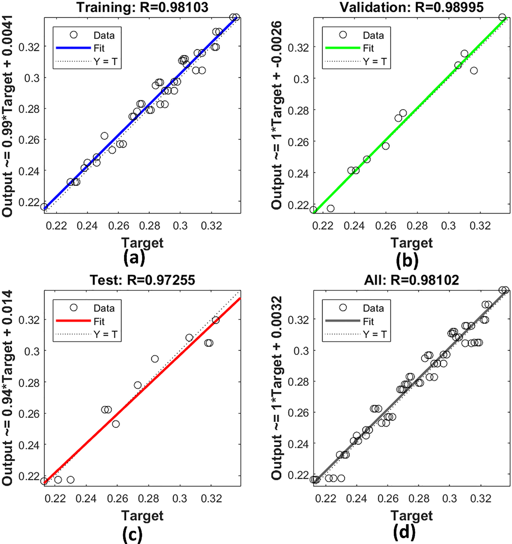
Figure 7: Regression plots for ANN model performance across (a) training, (b) validation, (c) testing, and (d) overall data sets.
The optimized ANN achieved an excellent coefficient of determination of
Fig. 8 presents a direct comparison of experimentally measured flank wear values and corresponding predictions obtained from the developed ANN model. Throughout the drilling trials, the ANN-predicted wear values closely track the experimental data, revealing nearly identical trends across all combinations of input parameters. The overlapping nature of the curves in this figure forms the basis for stating that nonlinear relationships exist between the process parameters of spindle speed, feed rate, and drill diameter, and their integrated effects on flank wear are effectively learned by the network. There are no large deviations between the two responses, thereby establishing the high reliability of ANN prediction and further strengthening its appropriateness as a soft sensor for real-time estimation of tool wear during GFRPC drilling operations.
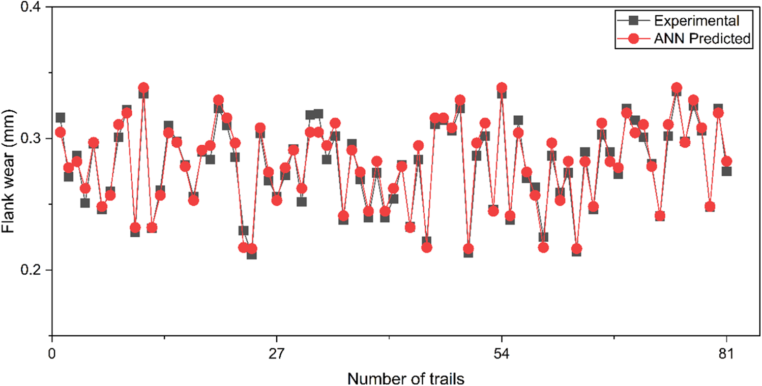
Figure 8: Comparison of experimental findings and ANN output.
4.5 Confirmation Testing and Reliability Assessment
To verify real-world applicability, eight additional drilling trials (Table 5), none of which are included in the training set, are used to assess performance further. The network’s predictions are compared to the measured flank wear values, and both absolute and percentage errors are calculated.
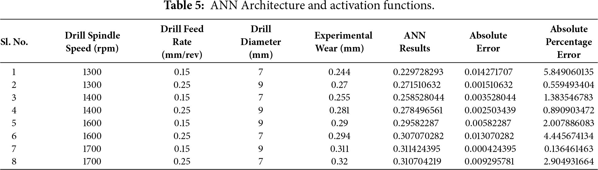
The mean absolute error is 0.006303 mm, and the mean absolute percentage error is only 2.27%. Every prediction error fall within ±0.01 mm, which is well below typical wear limits considered critical in composite machining. These results confirm that the ANN can reliably predict tool wear, making it suitable for real-time decision support.
Micrograph analysis provides direct insight into the wear mechanisms responsible for the progression of flank wear during the drilling of GFRPC laminates. Fig. 9 illustrates the condition of the drill cutting edge before and after drilling, thereby correlating microscopic observations with experimentally determined wear values.
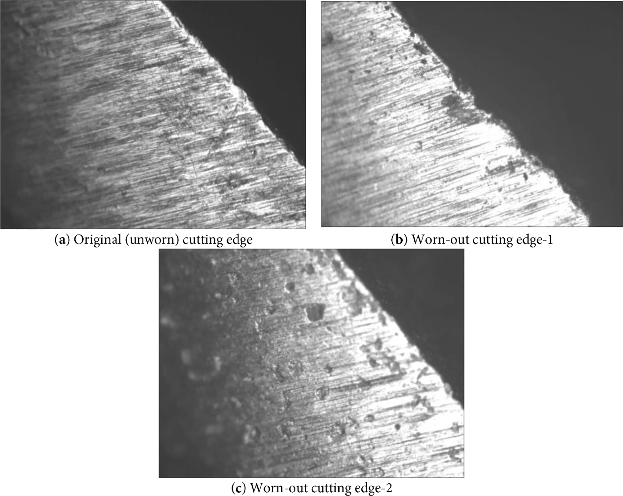
Figure 9: Optical micrographs of HSS drill flank surface.
In Fig. 9a, the original (unworn) cutting edge of the HSS drill is presented. The cutting edge appears sharp and well-defined, with a smooth flank surface and no signs of damage. This verifies the absence of pre-damaged areas, and thus all the wear features recognized in the following images derive solely from the drilling process.
The worn cutting edges after the drilling of the holes are shown in Fig. 9b,c. A clearly developed flank wear land is detected, which is characterized by the removal of the material along the flank face. The primary wear mechanism is abrasive wear, caused by the hard, brittle glass fibers sliding against the tool surface. The drill is rotating continuously, and the interaction between the drill and the exposed glass fibers leads to micro-grooving and scratching along the wear land.
Besides abrasion, localized edge rounding and microchipping can also be observed near the cutting edge. These characteristics suggest that mechanical loading and matrix thermal softening act in combination at higher spindle speeds. As the cutting temperature rises, the softened polymer matrix allows deeper fiber-tool interaction, thereby increasing abrasive action and accelerating wear progression. Small tool fragments detaching, in extreme cases, is an indication of the onset of fatigue and assisted wear due to repeated cyclic loading.
The difference in wear severity between Fig. 9b,c also indicates that drilling parameters affect wear development. Thus, the combination of higher spindle speed and feed rate results in more aggressive wear patterns due to increased frictional heat and thrust forces. These microstructural observations provide strong support for the statistical and ANN-based results, thereby confirming that spindle speed is the most significant factor influencing flank wear, followed by feed rate and drill diameter.
This study systematically investigates drill flank wear behavior during dry drilling of GFRP laminates and establishes a robust ANN-based predictive framework for intelligent machining applications. In a full-factorial experimental design, spindle speed is identified as the dominant parameter governing wear progression, accounting for 74.43% of the total variation, primarily due to intensified thermal softening of the matrix and severe abrasive interaction with glass fibers. Feed rate emerges as the second most influential factor, accelerating wear through increased thrust force and mechanical loading. At the same time, drill diameter exhibits a more minor, yet statistically significant contribution associated with extended tool-workpiece contact.
Although the developed linear regression model shows a high coefficient of determination, its inability to capture strong nonlinear interactions, particularly between spindle speed and feed rate, underscores the need for advanced modeling approaches. The proposed multilayer ANN model (3-10-6-1 architecture) trained using the Levenberg-Marquardt algorithm successfully learns these complex nonlinear relationships and achieves high predictive accuracy with low error metrics. Independent confirmation tests further validate the model, yielding a mean absolute percentage error of only 2.27%, with all predictions lying well within acceptable industrial wear limits.
Micrograph-based wear analysis corroborates the statistical and ANN findings by revealing abrasion-dominated wear mechanisms, edge rounding, and microchipping, particularly under high-speed, high-feed conditions. These experimental observations provide physical justification for the identified parameter rankings and reinforce the reliability of the proposed model.
The integration of systematic experimentation with ANN-based prediction presents a novel and reliable approach for real-time tool wear estimation in GFRP drilling. The proposed methodology offers significant potential for tool condition monitoring, process optimization, reduced tool consumption, and improved hole quality, thereby contributing to smart, data-driven, and sustainable manufacturing practices.
Acknowledgement: Not applicable.
Funding Statement: The authors received no specific funding for this study.
Author Contributions: The authors confirm contribution to the paper as follows: Conceptualization, Sathish Rao Udupi, Gururaj Bolar and Manjunath Shettar; methodology, Sathish Rao Udupi, Gururaj Bolar, Manjunath Shettar and Ashwini Bhat; software, Ashwini Bhat; validation, Sathish Rao Udupi, Gururaj Bolar and Manjunath Shettar; formal analysis, Sathish Rao Udupi, Gururaj Bolar and Manjunath Shettar; investigation, Sathish Rao Udupi and Gururaj Bolar; resources, Sathish Rao Udupi and Gururaj Bolar; data curation, Sathish Rao Udupi and Manjunath Shettar; writing—original draft preparation, Sathish Rao Udupi, Manjunath Shettar and Ashwini Bhat; writing—review and editing, Manjunath Shettar and Ashwini Bhat. All authors reviewed and approved the final version of the manuscript.
Availability of Data and Materials: The authors confirm that the data supporting the findings of this study are available within the article.
Ethics Approval: Not applicable.
Conflicts of Interest: The authors declare no conflicts of interest.
References
1. Karim MA, Abdullah MZ, Deifalla AF, Azab M, Waqar A. An assessment of the processing parameters and application of fibre-reinforced polymers (FRPs) in the petroleum and natural gas industries: a review. Results Eng. 2023;18(1):101091. doi:10.1016/j.rineng.2023.101091. [Google Scholar] [CrossRef]
2. Singh D, Kumar RR, Karsh PK, Kumar MK, Mandal GS, Sulfikhar Ali HM. Investigation on tribological and mechanical behaviour of GFRP composites with varying weight percentages of nano-graphite powders. Sci Rep. 2025;15(1):34924. doi:10.1038/s41598-025-18690-8. [Google Scholar] [PubMed] [CrossRef]
3. Chen Y, Zhang J, Li Z, Zhang H, Chen J, Yang W, et al. Manufacturing technology of lightweight fiber-reinforced composite structures in aerospace: current situation and toward intellectualization. Aerospace. 2023;10(3):206. doi:10.3390/aerospace10030206. [Google Scholar] [CrossRef]
4. Rajak DK, Wagh PH, Linul E. Manufacturing technologies of carbon/glass fiber-reinforced polymer composites and their properties: a review. Polymers. 2021;13(21):3721. doi:10.3390/polym13213721. [Google Scholar] [PubMed] [CrossRef]
5. Asyraf MRM, Ishak MR, Syamsir A, Amir AL, Nurazzi NM, Norrrahim MNF, et al. Filament-wound glass-fibre reinforced polymer composites: potential applications for cross arm structure in transmission towers. Polym Bull. 2023;80(2):1059–84. doi:10.1007/s00289-022-04114-4. [Google Scholar] [CrossRef]
6. Slamani M, Chatelain JF. A review on the machining of polymer composites reinforced with carbon (CFRPglass (GFRPand natural fibers (NFRP). Discov Mech Eng. 2023;2(1):4. doi:10.1007/s44245-023-00011-w. [Google Scholar] [CrossRef]
7. Xu J, Li L, Geier N, Davim JP, Chen M. Experimental study of drilling behaviors and damage issues for woven GFRP composites using special drills. J Mater Res Technol. 2022;21(1):1256–73. doi:10.1016/j.jmrt.2022.09.100. [Google Scholar] [CrossRef]
8. Abd-Elwahed MS. Drilling process of GFRP composites: modeling and optimization using hybrid ANN. Sustainability. 2022;14(11):6599. doi:10.3390/su14116599. [Google Scholar] [CrossRef]
9. Malik A, Pathak SR, Mali HS. Optimization of machining parameters during drilling of GFRP composite. In: Advanced engineering optimization through intelligent techniques. Singapore: Springer; 2024. p. 497–508. doi:10.1007/978-981-97-4654-5_43. [Google Scholar] [CrossRef]
10. Khashaba UA, Abd-Elwahed MS, Eltaher MA, Najjar I, Melaibari A, Ahmed KI. Thermo-mechanical and delamination properties in drilling GFRP composites by various drill angles. Polymers. 2021;13(11):1884. doi:10.3390/polym13111884. [Google Scholar] [PubMed] [CrossRef]
11. Xu J. A review on tool wear issues in drilling CFRP laminates. Front Mater. 2022;9:990773. doi:10.3389/fmats.2022.990773. [Google Scholar] [CrossRef]
12. Kulkarni GS, Siddeshkumar NG, Prasad CD, Shankar L, Suresh R. Drilling of GFRP with liquid silicon rubber reinforced with fine aluminium powder on hole surface quality and tool wear using DOE. J Bio Tribo Corros. 2023;9(3):53. doi:10.1007/s40735-023-00771-8. [Google Scholar] [CrossRef]
13. Yalçın B, Bolat Ç, Ergene B, Karakılınç U, Yavaş Ç, Öz Y, et al. Effect of drilling parameters and tool diameter on delamination and thrust force in the drilling of high-performance glass/epoxy composites for aerospace structures with a new design drill. Polymers. 2024;16(21):3011. doi:10.3390/polym16213011. [Google Scholar] [PubMed] [CrossRef]
14. Pereira AC, Monteiro SN, da Silva LRR, Binali R, Kuntoğlu M, Machado AR, et al. Machinability and surface integrity of glass fiber reinforced plastic composite: a review. J Mater Res Technol. 2025;35:6446–67. doi:10.1016/j.jmrt.2025.02.215. [Google Scholar] [CrossRef]
15. Balkan D. Delamination prediction in layered composites using optimized ANN algorithms: a comparative analysis. Symmetry. 2025;17(1):91. doi:10.3390/sym17010091. [Google Scholar] [CrossRef]
16. Chakraborty S, Chakraborty S. Applications of artificial neural networks in machining processes: a comprehensive review. Int J Interact Des Manuf. 2024;18(4):1917–48. doi:10.1007/s12008-024-01751-z. [Google Scholar] [CrossRef]
17. Abd-Elwahed MS. Multi-objective optimization of drilling GFRP composites using ANN enhanced by particle swarm algorithm. Processes. 2023;11(8):2418. doi:10.3390/pr11082418. [Google Scholar] [CrossRef]
18. Biruk-Urban K, Bere P, Józwik J, Leleń M. Experimental study and artificial neural network simulation of cutting forces and delamination analysis in GFRP drilling. Materials. 2022;15(23):8597. doi:10.3390/ma15238597. [Google Scholar] [PubMed] [CrossRef]
19. KP A, Vignesh Nayak U, Pranesh Rao KM, HT S, Neelakantha VL, CM S. Optimization of drilling parameters to minimize delamination in CNT-filled GFRP composites using machine learning. Appl Eng Sci. 2025;23(1):100257. doi:10.1016/j.apples.2025.100257. [Google Scholar] [CrossRef]
20. Zhu G, Hu S, Tang H. Prediction of tool wear in CFRP drilling based on neural network with multicharacteristics and multisignal sources. Compos Adv Mater. 2021;30(2):2633366X20987234. doi:10.1177/2633366X20987234. [Google Scholar] [CrossRef]
21. Hu S, Liu H, Feng Y, Cui C, Ma Y, Zhang G, et al. Tool wear prediction in glass fiber reinforced polymer small-hole drilling based on an improved circle chaotic mapping grey wolf algorithm for BP neural network. Appl Sci. 2023;13(5):2811. doi:10.3390/app13052811. [Google Scholar] [CrossRef]
22. Ze GK, Pramanik A, Basak AK, Prakash C, Shankar S, Radhika N. Challenges associated with drilling of carbon fiber reinforced polymer (CFRP) composites—a review. Compos Part C Open Access. 2023;11(1):100356. doi:10.1016/j.jcomc.2023.100356. [Google Scholar] [CrossRef]
23. Bhat A, Katagi NN, Gowrishankar MC, Shettar M. Prediction of water uptake percentage of nanoclay-modified glass fiber/epoxy composites using artificial neural network modelling. Comput Mater Contin. 2025;85(2):2715–28. doi:10.32604/cmc.2025.069842. [Google Scholar] [CrossRef]
24. Shettar M, Bhat A, Katagi NN. Estimation of mass loss under wear test of nanoclay-epoxy nanocomposite using response surface methodology and artificial neural networks. Sci Rep. 2025;15(1):19978. doi:10.1038/s41598-025-05263-y. [Google Scholar] [PubMed] [CrossRef]
Cite This Article
 Copyright © 2026 The Author(s). Published by Tech Science Press.
This work is licensed under a Creative Commons Attribution 4.0 International License , which permits unrestricted use, distribution, and reproduction in any medium, provided the original work is properly cited.
 Downloads
 Citation Tools