
 Submit a Paper
 Propose a Special lssue
 Open Access
ARTICLE

Numerical Mesoscale Analysis of Rubber Size, Rubber Content, and Specimen Size Effects on Crumb Rubber Concrete Using BFEM
1 Key Laboratory of Urban Security and Disaster Engineering, Ministry of Education, Beijing University of Technology, Beijing, China
2 Department of Architecture, Built Environment and Construction Engineering, Politecnico di Milano, Milano, Italy
3 China Institute of Building Standard Design Research, Haidian District, Beijing, China
4 Roads and Transportation Engineering Department College of Engineering, University of Al-Qadisiyah, Al Diwaniyah, Iraq
* Corresponding Author: Yijiang Peng. Email:
(This article belongs to the Special Issue: Advanced Computational Modeling and Simulations for Engineering Structures and Multifunctional Materials: Bridging Theory and Practice)
Computers, Materials & Continua 2026, 87(3), 40 https://doi.org/10.32604/cmc.2026.078775
Received 07 January 2026; Accepted 04 March 2026; Issue published 09 April 2026
 View Full Text
 Download PDF
Abstract
Crumb rubber concrete (CRC) has emerged as a sustainable solution to the environmental challenges posed by rubber waste. This study introduces an advanced mixed-random-aggregate mesoscale model for CRC based on the Base Force Element Method (BFEM) and the complementary energy principle. The model incorporates different rubber substitution ratios (0%–30%), rubber particle sizes (2 mm and 4 mm), and specimen dimensions (edge lengths of 100, 150, and 300 mm). These parameters are considered to investigate their effects on the mechanical properties and failure mechanisms of CRC. Accordingly, the numerical results include stress–strain responses, elastic modulus, and damage progression patterns. The results indicate that increasing rubber content leads to a pronounced reduction in both tensile and compressive strengths. This drop occurs mainly because rubber particles have a much lower elastic modulus. Thus, they represent stress concentrators and weak points, which accelerate the sample failure. Moreover, for the same replacement ratio, CRC with smaller rubber particles (2 mm) exhibits lower strength than CRC with larger particles (4 mm). This reduction occurs because the finer particles create more interfacial areas, introducing more sites for defect initiation and micro-cracks. In addition, increasing specimen size is associated with reduced strength and elastic modulus, highlighting size-dependent phenomena in CRC. The numerical predictions show good agreement with experimental results reported in the literature.Keywords
The world produces about 150 million waste tires each year, a number expected to reach 5 billion by 2030 [1]. As a response, recycling waste tires in construction has gained attention for its environmental, structural, and economic benefits [2]. An example of an effective recycling method of waste tires in construction is crumb rubber concrete (CRC), which addressing waste tire disposal issues and offers a sustainable alternative to traditional concrete [3]. Consequently, significant research has focused on the effectiveness of CRC in civil engineering applications [4].
Recent experimental investigations into rubberized concrete (CRC) have significantly advanced our understanding of its properties, particularly in mechanical behavior, durability, and rheological characteristics. The mechanical characterization of Crumb Rubber Concrete (CRC) currently relies on a standardized core system of experimental tests. The most fundamental and widely used is the compressive strength test, typically performed on cubic or cylindrical specimens subjected to axial loading until failure, which quantifies the impact of rubber content on the load-bearing capacity [5,6]. To evaluate tensile properties, the splitting tensile strength test (Brazilian splitting method) and the flexural strength test (three-point or four-point bending) are commonly employed [5,7]. These tests are sensitive to the performance degradation caused by the weak rubber-cement matrix interface [8]. Furthermore, the modulus of elasticity is determined from the stress-strain curve obtained during uniaxial compression or bending tests, a parameter that decreases markedly with increasing rubber content, indicating a reduction in material stiffness [8]. Recent experimental research has become more sophisticated. On one hand, pretreating crumb rubber (e.g., with chemical or chemico-thermal methods) to enhance the interfacial bond has emerged as a key experimental approach to improve the mechanical properties of CRC [9,10]. Concurrently, studying the synergistic effect of combining rubber with reinforcement materials like steel fibers on compressive, tensile, and flexural strengths represents another significant experimental focus [7]. Notably, incorporating rubber into concrete has been observed to lower its density, compressive strength, and elastic modulus while simultaneously augmenting ductility and energy absorption capabilities [11]. These alterations in CRC’s properties have been shown to be heavily dependent on factors such as rubber content, the size of rubber particles, and the type of binder employed [12,13]. However, a thorough understanding of CRC’s mesoscopic behaviors and the factors affecting its mechanical properties is still developing [14].
Alongside experimental investigations, numerical simulations have played a crucial role in enhancing our understanding of CRC [15,16]. These simulations offer a detailed perspective on the complex interactions occurring among aggregates, rubber particles, and the cement matrix, shedding light on the intricate mechanics of CRC [17]. In the finite element approach, CRC at the mesoscale is considered either a two-phase composite of concrete and rubber aggregate [18] or a multiphase composite with distinct interfaces [19]. Research focusing on CRC’s uniaxial compressive strength under static and impact loads uses two-dimensional models due to computational limitations [19]. The impact of aggregate shape on model calculations was investigated with circular, elliptical, and polygonal models compared to experimental data [20]. On the other hand, the particle discrete element method was employed to compare the energy development and meso-damage mechanisms in normal concrete and CRC [21]. Existing mesoscale modeling studies show that crumb rubber concrete (CRC) can be effectively represented as a heterogeneous multiphase composite. Furthermore, numerical simulations highlight the dominant role of rubber–mortar interfaces in mechanical degradation and demonstrate that simple two-dimensional models can efficiently approximate three-dimensional behavior. Despite these advances, most studies isolate individual parameters and use simplified aggregate shapes, which limit systematic assessment of coupled parameter interactions.
The principle of complementary energy is crucial for advanced modeling methodologies and has significantly advanced material behavior understanding. Within this framework, the Base Force Element Method (BFEM) has emerged as an effective technique for simulating fracture and damage in heterogeneous materials [22]. Building on Gao et al.’s base-force concept [23], Liu et al. [24] enhanced element stiffness matrix equations using the Lagrange multiplier method and developed a mid-node plane element model. This approach has shown high accuracy and applicability across various deformation scales and mesh shapes while maintaining reduced sensitivity to mesh distortion [24]. BFEM has been successfully applied to normal concrete and recycled aggregate concrete to study the meso-structure and mechanical properties, and fracture behavior [25]. In the context of CRC, BFEM has been applied to investigate mesoscale damage behavior under uniaxial loading [26]. The study validated the applicability of the BFEM framework for CRC by comparing rounded and convex aggregate representations within a single-polygon modeling configuration. The results confirmed the method’s capability to reproduce crack patterns and mechanical response [26]. However, that investigation was limited to one specimen size and a fixed rubber replacement. It did not explore the combined effects of rubber replacement ratio and rubber particle size, nor did it examine specimen size along with aggregate heterogeneity scaling. Consequently, the influence of multi-parameter coupling and heterogeneity scaling on the mechanical response and crack evolution in CRC remains insufficiently clarified within the BFEM framework.
This study presents a systematic mesoscale investigation of CRC using the BFEM based on energy principle, with emphasis on the coupled roles of rubber replacement ratio, rubber particle size, and specimen size in governing mechanical response and damage behavior. A mixed random-aggregate mesoscale model is adopted, using multi-polygonal coarse aggregates and circular rubber particles, to simulate uniaxial tensile and compressive loading. The study quantifies variations in tensile and compressive strengths. The influence of rubber content and particle size on crack initiation and propagation is analyzed at different loading stages. In addition, the work describes size-dependent mechanical responses through stress–strain behavior, elastic modulus evolution, peak and final strain variation, and failure morphology. Numerical results are validated against experimental data reported in the literature.
The CRC’s mesostructure model divides the material into five phases: coarse aggregates, rubber particles, mortar, and two types of interfacial transition zones (ITZ), as shown in Fig. 1. The studied variables of a BFEM model in this study are: (1) the shape of the coarse aggregate, (2) the amount of crumb rubber content, (3) the crumb rubber size, and (4) the effects of sample size on the CRC.
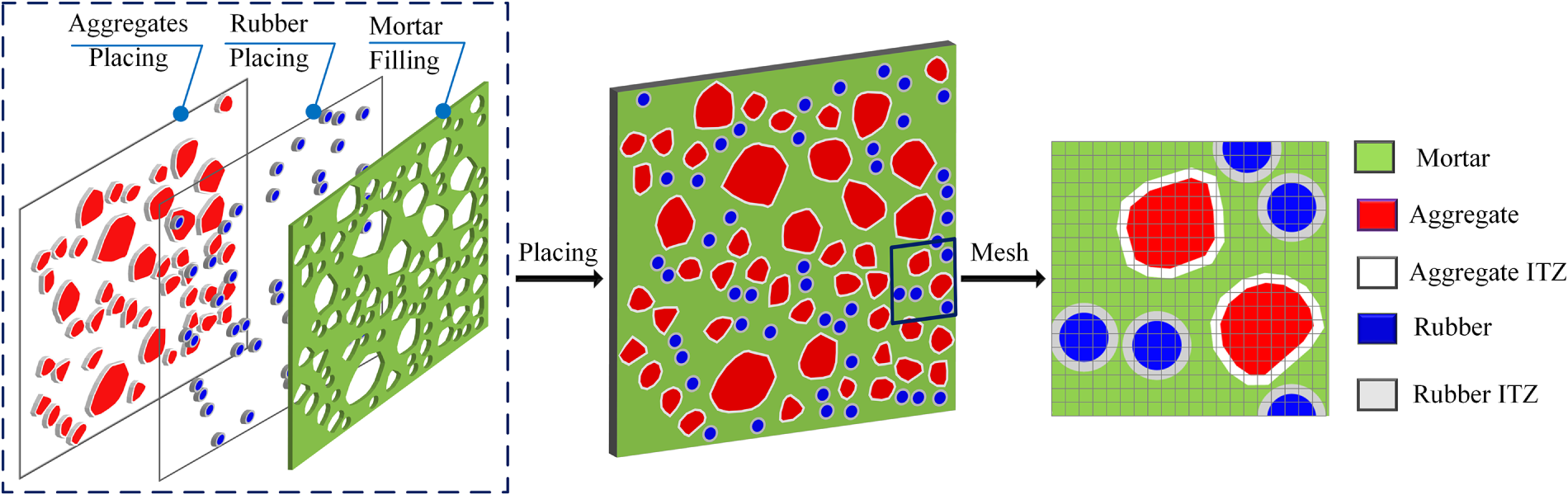
Figure 1: Aggregate, crumb rubber and mortar placing and meshing for CRC.
First, the volume of the coarse aggregate components is determined. The areal fraction of coarse aggregates within the concrete’s cross-section typically ranges from 30% to 60% [27]. Hence, the coarse aggregates were assumed to occupy 40% of the cross-sectional area for this model. The aggregate size distribution adopted in the mesoscale model follows a Fuller-type grading curve, widely used in concrete mix design to represent realistic aggregate packing and particle-size distributions. To translate the conventional three-dimensional grading into a two-dimensional mesoscale representation, the transformation proposed by Walraven and Reinhardt [28] is implemented. This approach enables the generation of a statistically equivalent aggregate distribution in plane models while preserving the physical meaning of volumetric grading. Although the experimental reference study used a maximum aggregate size of 16 mm [29], the present model uses 17.5 mm for the 100 mm × 100 mm specimen. This adjustment facilitates numerical discretization and size interval definition. Additionally, the difference is minor relative to the specimen dimensions and does not alter the overall characteristics of the grading curve, which are governed by the Fuller-type distribution. Based on the Walraven transformation of the Fuller grading, the cumulative distribution probability is expressed as:
where
The number of aggregate particles
where
The study further divides CRC specimens into three size categories: 100 mm × 100 mm, 150 mm × 150 mm, and 300 mm × 300 mm. This formulation generates aggregate sizes and counts that are statistically representative across different specimen sizes while preserving the mesoscale structure. The same distribution framework is applied consistently across all simulations. The aggregate size distribution is scaled proportionally with specimen dimensions to preserve geometric similarity in the mesoscale representation. Consequently, the maximum aggregate size (
While prevalent CRC models with random aggregates tend to represent these aggregates as circular shapes [30], this approach doesn’t fully capture their real-world complexities. To address this, the developed model treats convex polygonal coarse aggregates based on polygonal aggregate generation methodologies [31]. This assumption is consistent with earlier experimental and numerical research, which shows polygonal aggregate models better capture interlocking effects and fracture patterns in concrete materials [32,33]. Rubber particles are retained in circular form. This approach is divided into two main steps: First, the “Polygonal Base Framework Formation”. For each aggregate, a polygonal base framework is formed by randomly generating a number of points along its boundary, where this number is proportional to the particle diameter (D). Larger aggregates are assigned to a higher number of vertices (
The second step is the “Extension of the Aggregate Base Framework”. Once the polygonal base framework is established, its area is incrementally expanded outward to approximate the area of a rounded aggregate. Edges with greater lengths are prioritized for extension. The new vertex coordinates after each extension are computed as:
where, (
The extension constraints of the approach are: (1) The newly inserted vertex must lie within the specimen’s boundaries. (2) The length of any new edge must exceed
The rubber components of the CRC mix are modelled. Rubber particles generally have a diameter of less than 5 mm, categorizing them as fine aggregate. Based on the experimental data [29], the ratio of the volume of fine aggregate to the total volume, denoted as
where c is the replacement percentage of rubber,
This study uses a two-dimensional plane mesoscale model for simulation analyses. The experimental specimens from the literature are three-dimensional cubic samples. However, a 2D representation is commonly used in mesoscale analyses of concrete and crumb rubber concrete [37,38]. This approach captures the main mechanisms of stress redistribution, crack initiation, and crack propagation. Aggregates, rubber particles, and interfacial transition zones govern these mechanisms. The model aims to compare mechanical trends and mesoscale damage evolution, but does not capture the full three-dimensional stress state. This is noted as a limitation. The CRC specimens are grouped into three size categories: 100 mm × 100 mm, 150 mm × 150 mm, and 300 mm × 300 mm. This division examines their impact on model output.
Utilizing the Monte Carlo method, this research employs a random placement strategy for coarse aggregates and crumb rubber particles within the model using FORTRAN code [31]. This involved defining the boundaries and coordinate system based on the dimensions of the specimen and producing uniformly distributed random numbers to obtain coordinates for aggregate distribution. The obtained coordinates were then subject to specific constraints concerning dimensions and distances between centers (1.1 times the combined diameters of the aggregates). To reduce the influence of aggregate randomness, three independent simulations with distinct random aggregate and rubber-particle distributions were performed for each CRC configuration. The results reported in this study correspond to mean values obtained from these simulations. The coefficients of variation are between approximately 2%–5% in tension and 0.5%–3% in compression. These results suggest that random particle placement exerts minimal influence on the observed trends and confirm the statistical robustness of the numerical findings. The subsequent process involves dividing the mesh into segments and assigning specific parameters to each mesh element, ensuring a comprehensive and systematic approach to the model’s development, as shown in Fig. 1. This study employs a rectangular mesh with edge-center nodes featuring a partition step of 0.5 mm. The literature shows that this mesh size balances accuracy and computational efficiency in BFEM-based mesoscale concrete simulations [31,39]. It also captures interfacial transition zones and mesoscale cracks efficiently. The characterization of each mesh element is determined based on the spatial relationship between the nodes and the aggregate components. Depending on their positions, the meshes are categorized as aggregate, rubber, mortar, or as an ITZ mesh when situated between aggregate or rubber and mortar. Current numerical simulations apply displacement-controlled loading at the top boundary for uniaxial tension or compression, while the bottom boundary is constrained to prevent rigid-body motion.
2.2 Base Force Element’s Stress and Strain Formulations
In the Base Force Element Method (BFEM), the structural elements feature mid-side nodes, enhancing their analytical capacity. The formulation of the governing equations relies on the complementary energy principle, avoiding the need for interpolation functions, as detailed in the literature [31]. This method is illustrated in the four-node planar fundamental nodal force element. The points I, J, M, N represent the midpoints of the four sides, and the resultant forces exerted at these midpoints are denoted by
When the element size is sufficiently small, the stress deviation can be neglected. The stress (
Assuming that stress is uniformly distributed on each face:
where,
For planar elements, the equation can be formulated as follows:
where,
By substituting
where,
The matrix form is:
The explicit expression for node displacement
where,
Substituting
in which, I represents the I-th edge and J stands for the J-th edge of the element.
2.3 Loading Models and Damage Constitutive Parameters
The mesoscopic tension and compression load models used in the BFEM simulations are shown in Fig. 2. In the tensile model, a uniform load is applied at the top, with displacement incrementally increased at a rate of 0.001 mm per load step. For the compression model, an equal displacement increment of 0.01 mm per load step is applied to generate a uniformly distributed compressive load. Regarding the boundary conditions, vertical displacement at all nodes along the bottom is fixed to eliminate rigid-body motion. In addition, the bottom central node is additionally constrained in the horizontal direction. These conditions are applied in both tension and compression loading cases.
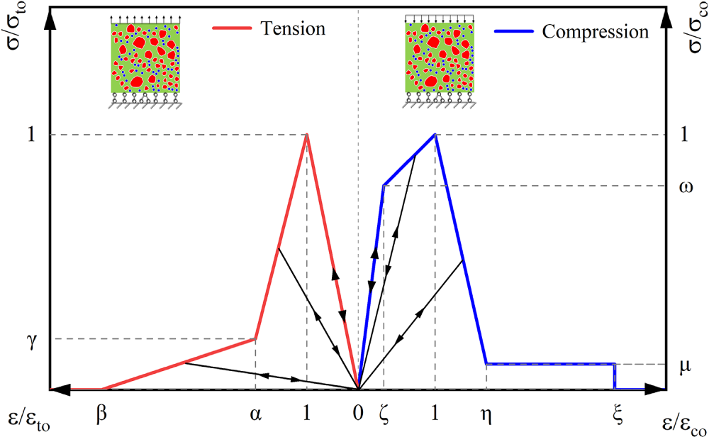
Figure 2: Damage model curves and loading models.
In CRC analysis, significant non-linear behavior occurs as materials approach peak stress. To accurately capture this phenomenon, a damage constitutive model is employed to enhance the simulation of the damage process. This model, illustrated in Fig. 2, incorporates both tensile and compressive damage factors, which better represent the material’s response to various loading conditions [40]. The inclusion of crumb rubber significantly alters CRC’s mechanical properties due to its lower strength and weaker bond with mortar compared to traditional aggregates. The rubber phase is modeled as a linear elastic material without damage. Mesoscale simulations of CRC under uniaxial loading show that rubber particles develop strains below approximately 0.02 [37]. These strains are considerably lower than the ≈0.15 strain threshold at which tire-derived rubber begins to exhibit nonlinear or damage behavior [41]. Thus, a linear elastic representation adequately captures the mechanical response of rubber in this framework.
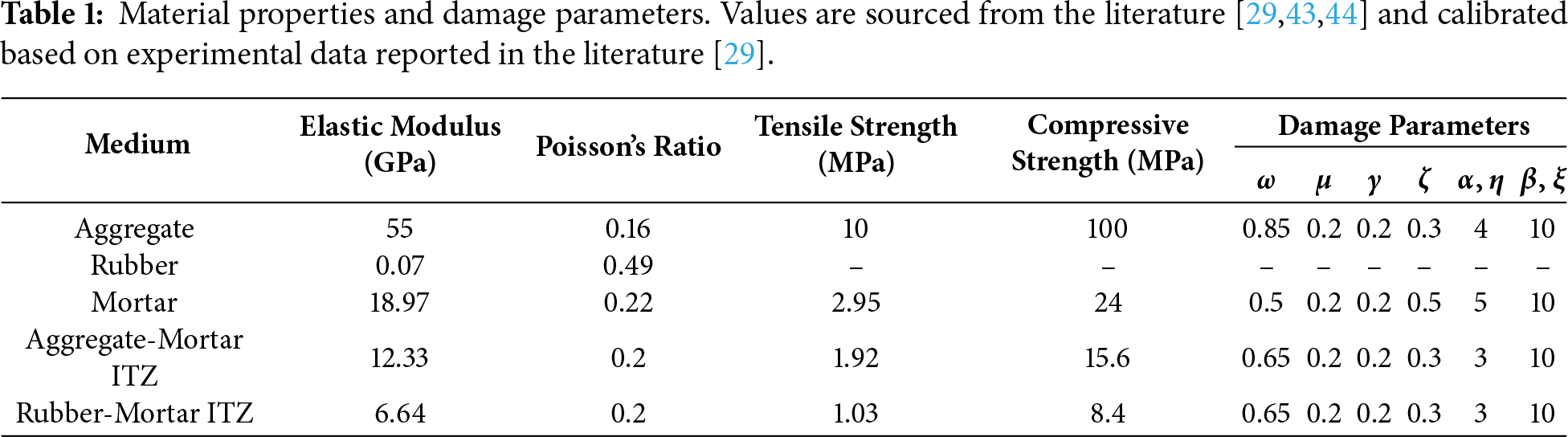
In this research, the cubic specimen of CRC is simplified into a two-dimensional plane model, leading to the development of the CRC mixed random aggregate model. The interfacial transition zone (ITZ), crucial in concrete mesoscale studies, is modeled with a thickness between 0.1 and 1 mm, as studies indicate minimal impact on mechanical properties within this range [42]. The model incorporates 0.5 mm × 0.5 mm quadrilateral meshes. Material parameters are sourced from the literature [43] and empirical formulas, considering the water-cement ratio in CRC [29]. The aggregate and mortar ITZ parameters are set at 65% of the mortar parameters and for the rubber-mortar interface at 35% [44]. The Poisson’s ratio for ITZ, challenging to ascertain experimentally, is approximated at 0.2 [40]. The constitutive model parameters are deduced inversely based on the strength and modulus of elasticity of each phase. The detailed material parameters for the five phases are presented in Table 1.
In the uniaxial tension simulations, crack initiation and propagation are governed by mode-I fracture mechanisms. In this mode, isotropic damage constitutive models adequately describe the meso-structural behavior of concrete [45]. Therefore, the mesoscale CRC model is treated as macroscopically isotropic under uniaxial tension. This approach aligns with established damage-based modeling methods reported in the literature [46].
The base force element method (BFEM), formulated within the complementary energy principle, has been applied to fracture and damage analysis of heterogeneous cementitious materials, including normal concrete and recycled aggregate concrete [24,25]. These studies demonstrated that the method provides a stable numerical simulation of mesoscale crack initiation and propagation. On this basis, BFEM is adopted in the present study for mesoscale modeling of crumb rubber concrete.
3.1 Influence of Rubber Content and Particle Size
Crumb rubber concrete, produced by substituting fine aggregates with rubber particles of varying sizes in equivalent volume, exhibits distinct mechanical properties owing to rubber’s unique strength, elasticity, and adhesion characteristics compared to traditional aggregates. The rubber’s volume and particle size notably influence these properties. Utilizing the previously mentioned mixed random aggregate model, this section employed numerical simulations on 100 mm × 100 mm specimens with rubber particle sizes of 4 and 2 mm and rubber contents of 10%, 20%, and 30%. To mitigate the impact of aggregate randomness, each CRC type underwent three random placements, with a standard concrete set acting as a control. Specimens were labeled as CRC-d-r, where d is the rubber particle size in millimeters and r is the rubber content percentage by volume. For instance, CRC-4-10 represents a specimen with 4 mm rubber particle size and 10% rubber content. PC denotes plain concrete.
Numerical simulations were performed on CRC specimen models with different rubber particle sizes and rubber contents using the complementary energy principle-based surface force element method. The loading model is the same as mentioned earlier. The obtained simulation results were compared with the experimental results of Hu et al. [29]. In those experiments, crumb rubber particles ranged in size from 2 to 5 mm. From Fig. 3a, the tensile strength of plain concrete is 1.651 MPa. When rubber particles with a diameter of 4 mm are added, the tensile strength of CRC with rubber contents of 10%, 20%, and 30% is 1.106, 0.960, and 0.829 MPa, respectively, accounting for 67%, 58%, and 50% of the plain concrete strength. When rubber particles with a diameter of 2 mm are added, the tensile strength of CRC is 1.141, 0.922, and 0.735 MPa, respectively, accounting for 69%, 56%, and 45% of the plain concrete strength. It is evident that as the rubber content increases, the tensile strength of CRC significantly decreases, with the maximum reduction being 55%. When 10% rubber is added, the rate of strength decrease is relatively large, but this rate slows down as the content increases. This pattern is consistent with other experimental data [47,48]. Fig. 3b states that for a 10% rubber content, the tensile strength of CRC with a 2 mm particle size slightly exceeds that of the 4 mm size. However, with a 20% rubber content, the tensile strength of CRC with 2 mm rubber particles drops by 3.4% compared to the 4 mm variant. This decline intensifies with a rubber dosage of 30%, recording a 10% reduction. As rubber content ranges between 20% and 30%, the tensile strength of CRC with 2 mm particle size is consistently lower than that of 4 mm, with this disparity widening with increased rubber content. This decline in strength can be attributed to the enlarged specific surface area as rubber particle size diminishes, amplifying the rubber-mortar ITZ and consequently making the concrete more prone to damage.
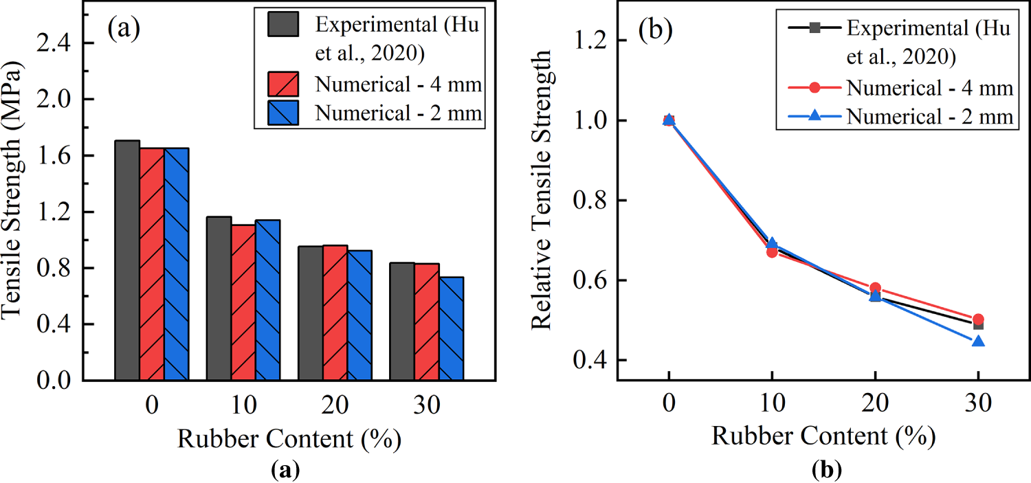
Figure 3: Effect of rubber particle size and content on tensile strength of CRC under uniaxial tension: (a) Tensile strength (MPa); (b) Relative tensile strength.
The illustration of the tensile damage evolution of CRC under different rubber particle sizes and contents is shown in Fig. 4a–g. From the figures, it can be seen that the tensile failure characteristics of each group of CRCs are roughly the same as in the previous section. Cracks first appear in areas where the rubber is denser, and the cracks gradually begin to extend perpendicular to the loading direction, connecting with other cracks and the ITZ cracks with the aggregates, forming one or two main cracks, eventually leading to the failure of the specimen. However, the difference is that as the rubber particle size decreases and the dosage increases, small cracks will appear in the rubber concentration area during failure.
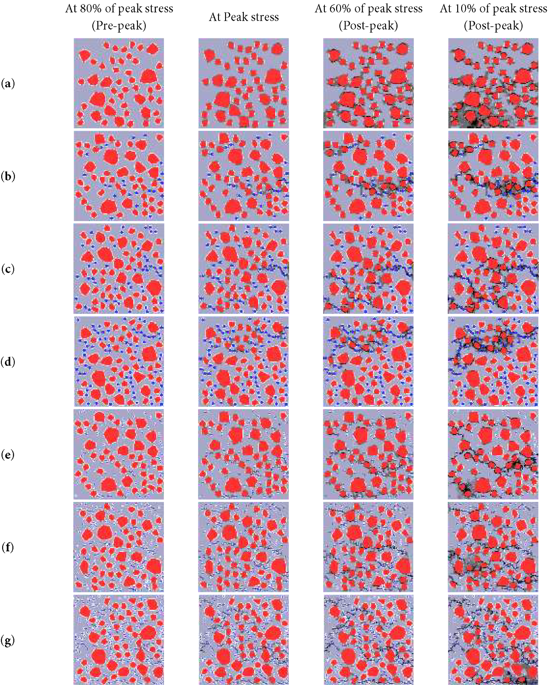
Figure 4: Tensile failure evolution of plain concrete and crumb rubber concrete with different rubber size and contents at different stress levels: (a) PC; (b) CRC-4-10; (c) CRC-4-20; (d) CRC-4-30; (e) CA-2-10; (f) CRC-2-20; (g) CRC-2-30. Black spots represent the crack path.
The loading model presented in Fig. 2 is used to simulate the uniaxial compression of CRC specimen models with different rubber particle sizes and different rubber contents. The simulation results are compared with the experimental results of Hu et al. [29], in which the crumb rubber particles ranged in size from 2 to 5 mm. The numerical simulation results are shown in Fig. 5a. The compressive strength decreases with the increase of the replacement ratio for both rubber sizes [49]. For a 4 mm rubber size, the reduction in compressive strength is recorded at 33%, 42%, and 50% for the crumb rubber replacement ratios of 10%, 20%, and 30%, respectively. At the same time, the decline is 39%, 44%, and 56% for 2 mm rubber content, 10%, 20%, and 30%, respectively. The compressive strengths of the 4 mm group are more comparable to the experimental results. According to Fig. 5b, as rubber content rises from 10% to 30%, the compressive strength of CRC with a 2 mm particle size decreases by 1.4%, 5%, and 13%, respectively, when compared to its 4 mm counterpart. This reduced strength correlates with an increase in the specific surface area of the smaller rubber particles, enhancing the rubber-mortar ITZ and generating the concrete more susceptible to damage. The former experimental studies of different crumbed rubber sizes in concrete reached the same conclusion [34].
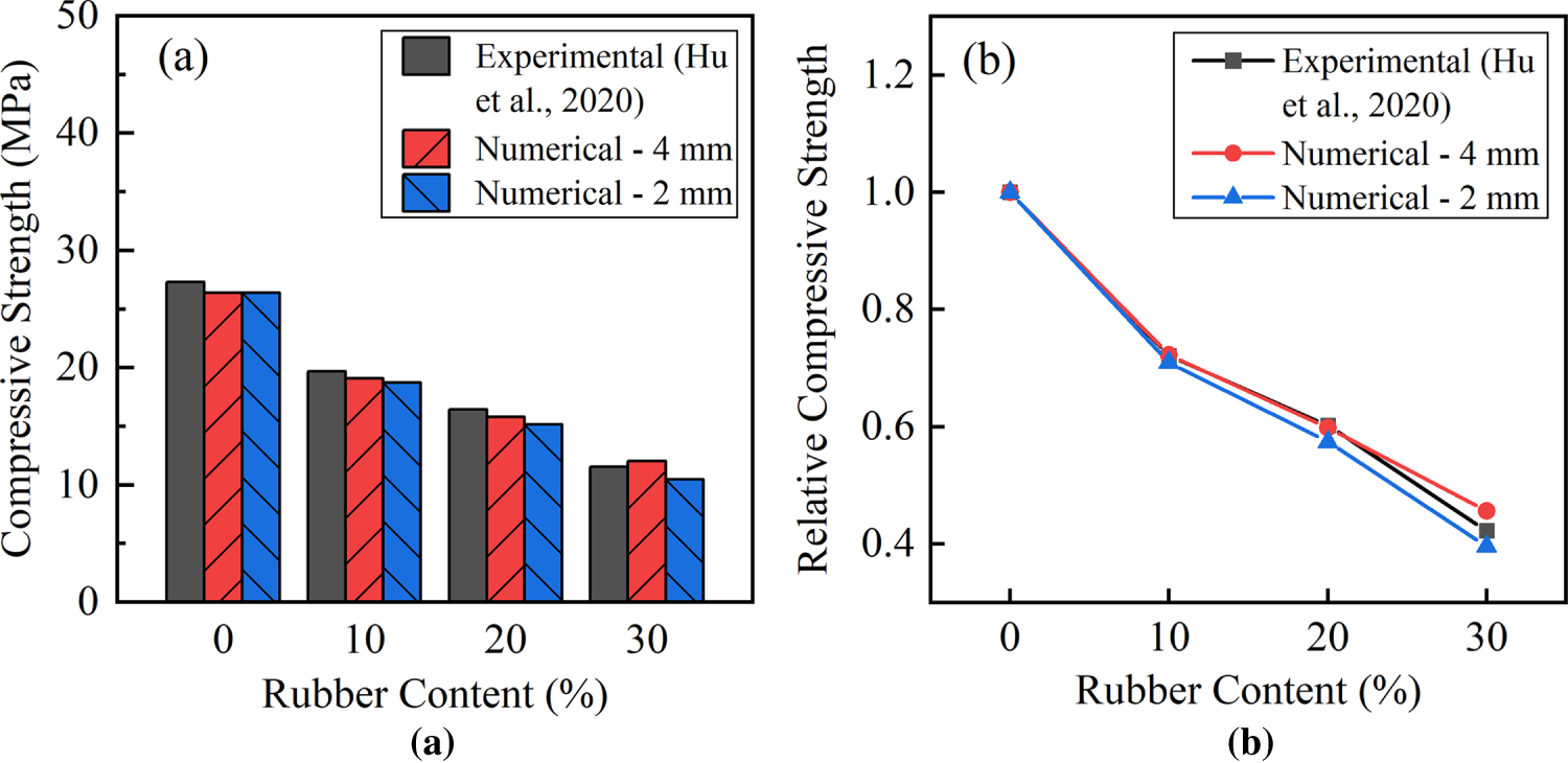
Figure 5: Effect of rubber particle size and content on compressive strength of CRC under uniaxial compression: (a) Compressive strength (MPa); (b) Relative compressive strength.
Fig. 6a–g details the compressive failure mechanism of CRC across varied particle sizes and contents, aligning with the observations from the literature [26]. Damage initiates in rubber-dense regions, evolving from diagonal meshes to fork-shaped units surrounding the rubber, culminating in specimen failure. Notably, higher rubber contents and a 2 mm particle size intensify the frequency, fineness, and dispersion of cracks compared to those with a 4 mm particle size.
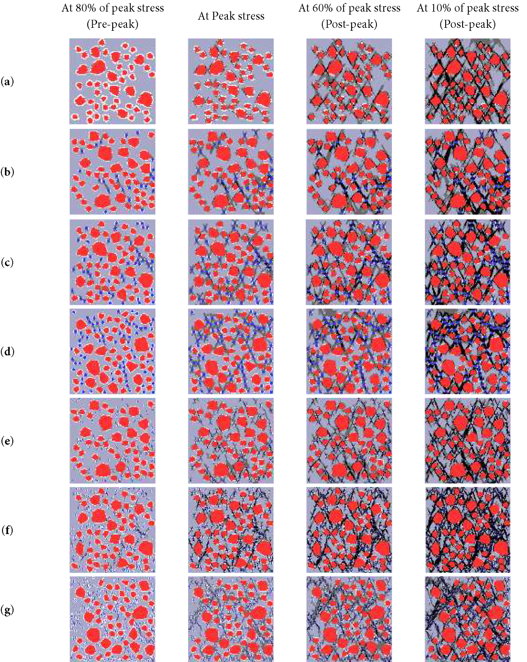
Figure 6: Compressive failure evolution of plain concrete and crumb rubber concrete with different rubber size and contents at different stress levels: (a) PC; (b) CRC-4-10; (c) CRC-4-20; (d) CRC-4-30; (e) CA-2-10; (f) CRC-2-20; (g) CRC-2-30. Black spots represent the crack path.
3.2 Size Effect of Crumbed Rubber Concrete
Utilizing the preceding modeling and computational techniques, this part conducts uniaxial tension and compression simulations on cubic CRC specimens with 100, 150, and 300 mm dimensions. The aim is to analyze the mechanical properties of CRC across different specimen sizes, thus ascertaining the size effect inherent in CRC. The specimens comprise a rubber content of 20%, a rubber particle size of 4 mm, and fine aggregates constituting 30% of the overall volume. Material and constitutive parameters align with those delineated in Table 1.
This study conducted uniaxial tensile numerical simulations on three distinct size categories of CRC specimens. Fig. 7 shows the stress–strain curves of CRC specimens with different sizes under uniaxial loading. The tensile stress-strain curves of three different sizes of CRC specimens are consistent in shape (Fig. 7a). The slope of the linear zone shows slight differences among the three sizes. However, the samples exhibit varying values at the curve’s peak and softening sections. The peak tensile strength and softening decrease with the increase in sample size.
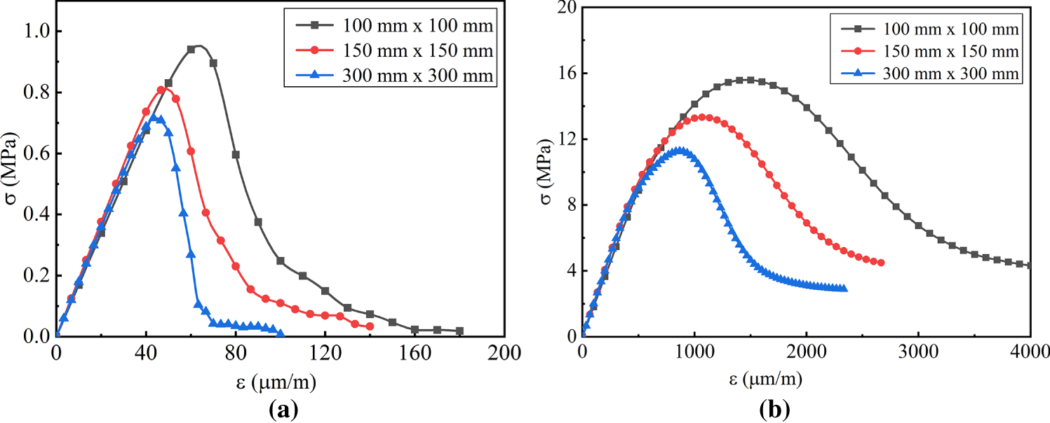
Figure 7: Stress-strain curves of CRC specimens with different sizes under uniaxial loading: (a) Tensile stress (MPa); (b) Compressive stress (MPa).
The peak tensile stress and modulus of elasticity of CRC due to the size effect are shown in Fig. 8a. The peak strength values reached 0.94, 0.81, and 0.72 MPa, while the modulus of elasticity values were 17, 18.8, and 17.9 GPa for the samples measuring 100 mm × 100 mm, 150 mm × 150 mm, and 300 mm × 300 mm, respectively. When the specimen size is 150 mm, the peak tensile strength is reduced by 14% compared to the specimen size of 100 mm, and when the specimen size is 300 mm, the tensile strength is reduced by 24% compared to the specimen size of 100 mm. In contrast, no clear trend was observed regarding the changes to the elastic modulus. The 150 mm × 150 mm specimen showed an increase of 11%, while the 300 mm × 300 mm specimen experienced a 6% increase. Overall, the size effect on elastic modulus is less pronounced than on tensile strength. Additionally, CRC exhibits a size effect similar to that of ordinary concrete when subjected to tension, and the effect is even more pronounced in CRC [50]. Fig. 8b shows the peak and final strains. As the CRC sample size increased, the peak and final strains decreased. The peak strain decreased by 14% and 24%, while the final strain decreased by 22% and 27% for the specimens measuring 150 mm × 150 mm and 300 mm × 300 mm, respectively.
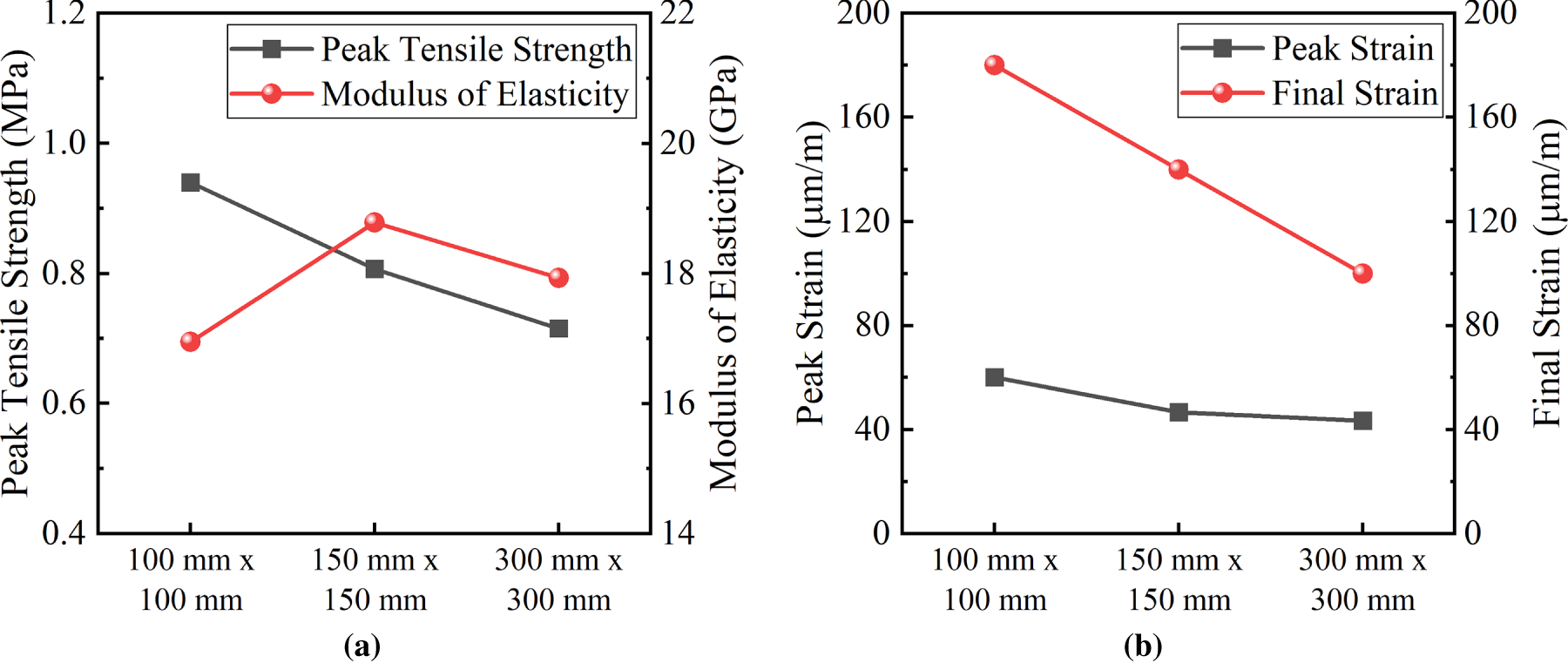
Figure 8: Uniaxial tension results of CRC specimens with different sizes: (a) Peak tensile strength (MPa) and modulus of elasticity (GPa); (b) Peak and final strains (μm/m).
Fig. 9a–c presents the uniaxial tensile failure visuals for CRC across varied sizes. The observed failure morphologies are congruent across specimen sizes, characterized by cracks oriented perpendicular to the applied load. Intriguingly, with an uptick in the CRC’s size, there is an expansion of weak ITZ regions surrounding the rubber, leading to a concurrent surge in the number of cracks at the point of failure. Similar damage patterns resulting from size effects in conventional concrete have been documented in the literature [51].
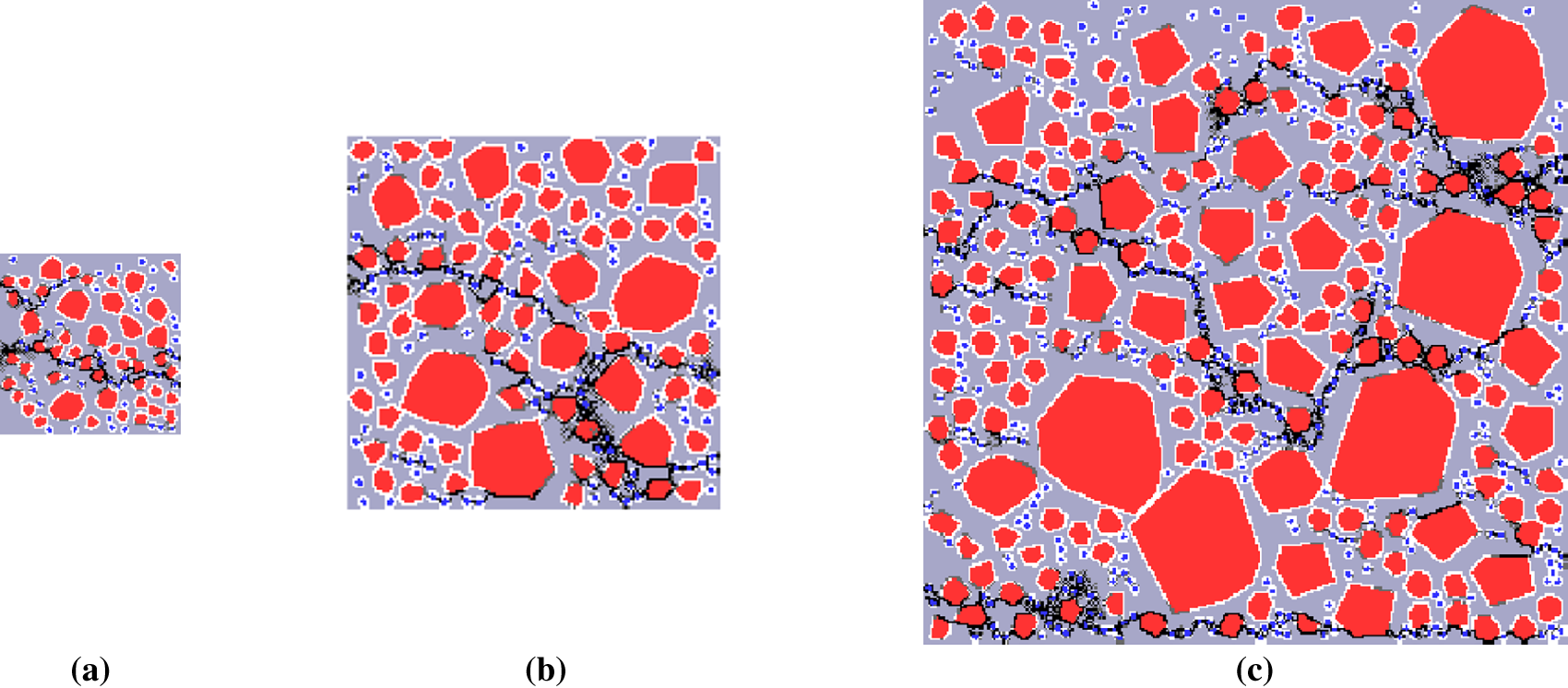
Figure 9: Failure crack pattern of CRC specimens with different sizes under uniaxial tension: (a) 100 mm × 100 mm; (b) 150 mm × 150 mm; (c) 300 mm × 300 mm. Black spots represent the crack path.
Numerical simulations were conducted on three groups of CRC specimens of varying sizes. The compression stress-strain curves are displayed in Fig. 7b. The elastic zones of the stress-strain curve are remarkably similar. However, a notable deviation exists between the different sizes at the nonlinear ascending zone (peak) and the descending (softening) zone. The compressive strength and peak stress of CRC decrease with the increase in the specimen size, as illustrated in Fig. 10a. The compressive strength of the specimen with a size of 150 mm is reduced by 14.5% compared to the specimen with a size of 100 mm, and the compressive strength of the specimen with a size of 300 mm is reduced by 27.7% compared to the specimen with a size of 100 mm. In contrast, the elastic modulus of CRC increased due to the size effect. The elastic modulus increases by 12% for 150 mm specimens and 11% for 300 mm specimens compared to the 100 mm specimens. In summary, CRC has a size effect similar to conventional concrete during uniaxial compression [50], and it is more pronounced than in concrete. This is because the size effect of concrete material is related to the number of cracks generated by defect expansion during loading. In numerical simulations, larger specimens form more cracks during the loading process due to weaker ITZ areas, resulting in a reduction in strength for larger specimens. For CRC, adding rubber particles further increases the number of weak areas in the specimen, resulting in a more significant size effect [50].
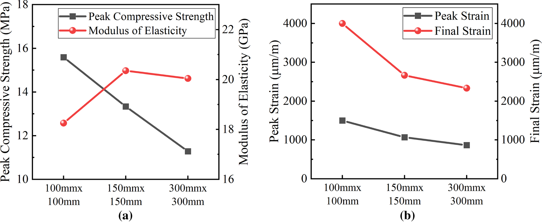
Figure 10: Uniaxial compression results of CRC specimens with different sizes: (a) Peak compressive strength (MPa) and modulus of elasticity (GPa); (b) Peak and final strains (μm/m).
As shown in Fig. 10b, the impact of the specimen size on CRC under compression load is more pronounced in strains than in stresses. For the 150 mm specimen, the peak strain is reduced by 20%, and the final strain is reduced by 33% compared to the 100 mm specimen. In the case of the 300 mm specimen, both the peak and final strains are reduced by 42% when compared to the same strains observed in the 150 mm specimen.
Fig. 11a–c shows the failure diagrams of specimens of different sizes under uniaxial compression. As can be seen from the figure, the failure pattern of specimens of different sizes is consistent, with cracks extending obliquely centered around the rubber, forming a fork shape. However, it can be clearly seen that the larger the size of the CRC, the more cracks there are. This is because the larger the specimen, the weaker ITZ areas around the rubber, making it more susceptible to failure [51].
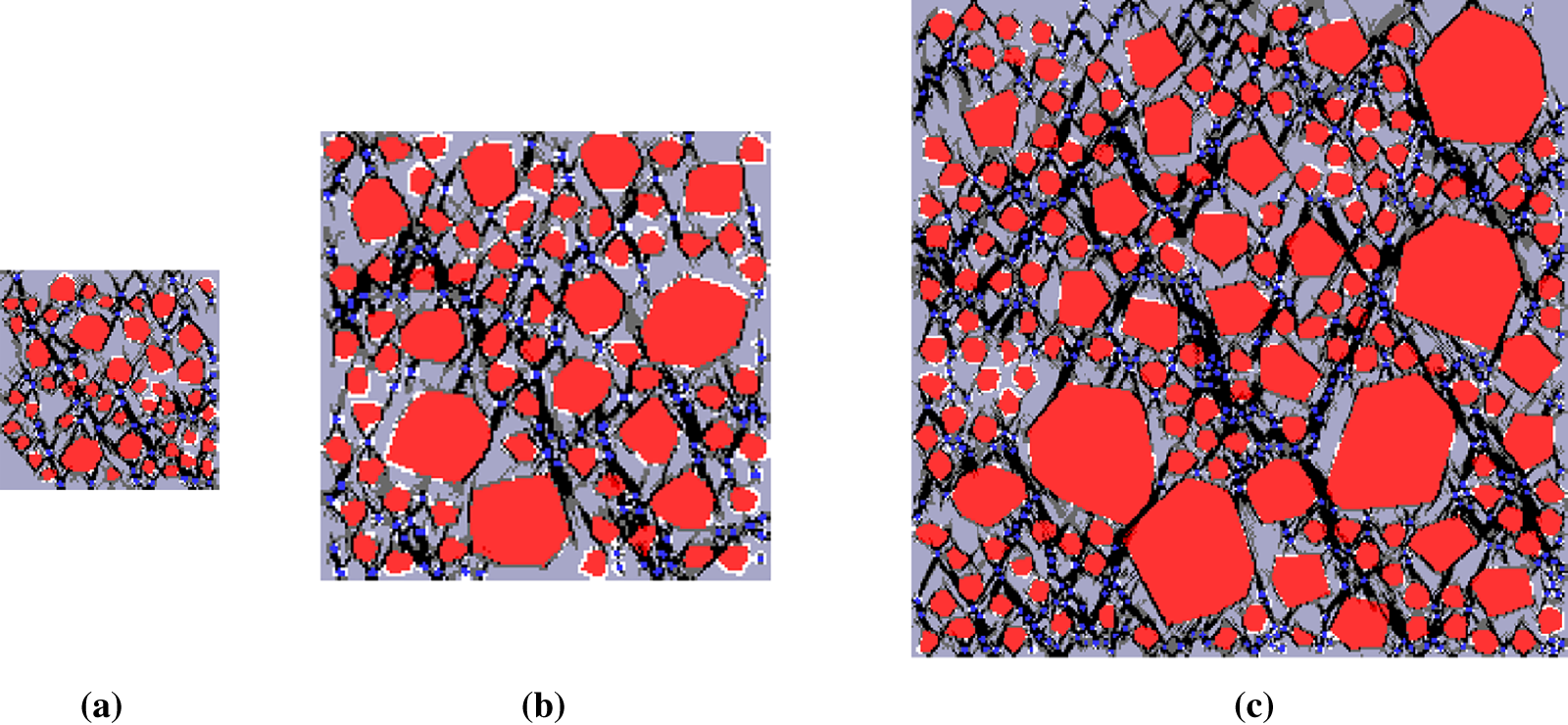
Figure 11: Failure crack pattern of CRC specimens with different sizes under uniaxial compression: (a) 100 mm × 100 mm; (b) 150 mm × 150 mm; (c) 300 mm × 300 mm. Black spots represent the crack path.
This study advances understanding of crumb rubber concrete (CRC) by developing a novel mixed-random-aggregate mesoscale model. Systematic numerical analyses are conducted using the Base Force Element Method (BFEM). The model includes convex polygonal coarse aggregates and circular rubber particles. This procedure allows accurate simulation of CRC’s mechanical behavior and damage mechanisms under uniaxial tension and compression. Key parameters are investigated, including rubber substitution ratio (0%–30%), rubber particle size (2 and 4 mm), and specimen size (100 mm × 100 mm, 150 mm × 150 mm, 300 mm × 300 mm). These factors provide insights into optimizing CRC’s performance in sustainable construction. The numerical results are validated against experimental data from the literature. They display consistent trends in CRC’s structural response. Crack initiation mainly occurs in rubber-dense regions and interfacial transition zones (ITZs). Propagation pathways connect these weak areas to form main cracks that lead to specimen failure. Increasing the rubber content significantly reduces both tensile and compressive strengths. At 30% rubber substitution, maximum reductions of 55% in tensile strength and 56% in compressive strength are observed. Rubber particle size also influences strength. At the same substitution ratio, larger particles (4 mm) yield higher strength than smaller ones (2 mm). This effect is attributed to the larger specific surface area of smaller particles, which intensifies ITZ weakness. Additionally, CRC shows a marked size effect. Peak tensile and compressive strengths decrease with increasing specimen size. Reductions reach up to 27.7% for 300 mm specimens compared to 100 mm ones. This effect is more notable than in conventional concrete due to additional weak zones introduced by rubber particles. CRC’s stress–strain response shows negligible rubber influence in the initial elastic stage. However, it exhibits distinct softening near peak stress, mainly under compression. CRC demonstrates a more gradual post-peak behavior than plain concrete. The present work uses a 2D mesoscale representation with simplified geometric assumptions. Aggregates are randomly distributed. Crumb rubber particles are treated as idealized circles rather than irregular shapes. These simplifications allow efficient parametric analyses but may influence local stress states and crack initiation mechanisms. To address potential limitations, future work will incorporate realistic aggregate morphology and shape-informed rubber-particle representations. With these improvements, the accuracy of mesoscale simulations is expected to increase. In summary, this research clarifies CRC’s mesoscopic mechanisms and presents a modeling approach for optimizing mix proportions and structural applications. These findings support waste tire recycling and reduce environmental impact, advancing sustainable construction materials.
Acknowledgement: During the preparation of this manuscript, the authors utilized ChatGPT (version GPT-5.2, OpenAI) for assistance in text refinement. The authors have carefully reviewed and revised all AI-assisted content and accept full responsibility for the accuracy and integrity of the manuscript.
Funding Statement: This work is supported by National Science Foundation of China (10972015, 11172015), the Beijing Natural Science Foundation (8162008).
Author Contributions: The authors confirm contribution to the paper as follows: Conceptualization, Yijiang Peng; methodology, Yijiang Peng and Mahmoud M. A. Kamel; validation, Mahmoud M. A. Kamel and Yu Fu; formal analysis, Yu Fu; investigation, Mahmoud M. A. Kamel, S. Z. Abeer; resources, S. Z. Abeer; writing—original draft preparation, Mahmoud M. A. Kamel; writing—review and editing, Yijiang Peng and Zaman Mohamed AL-Delfi; visualization, Mahmoud M. A. Kamel and Yu Fu; supervision, Yijiang Peng. All authors reviewed and approved the final version of the manuscript.
Availability of Data and Materials: The data that support the findings of this study are available from the Corresponding Author, Yijiang Peng, upon reasonable request.
Ethics Approval: Not applicable.
Conflicts of Interest: The authors declare no conflicts of interest.
References
1. Islam MMU, Li J, Wu YF, Roychand R, Saberian M. Design and strength optimization method for the production of structural lightweight concrete: an experimental investigation for the complete replacement of conventional coarse aggregates by waste rubber particles. Resour Conserv Recycl. 2022;184(1):106390. doi:10.1016/j.resconrec.2022.106390. [Google Scholar] [CrossRef]
2. Sofi A. Effect of waste tyre rubber on mechanical and durability properties of concrete—a review. Ain Shams Eng J. 2018;9(4):2691–700. doi:10.1016/j.asej.2017.08.007. [Google Scholar] [CrossRef]
3. Martínez-Barrera G, del Coz-Díaz JJ, Álvarez-Rabanal FP, López Gayarre F, Martínez-López M, Cruz-Olivares J. Waste tire rubber particles modified by gamma radiation and their use as modifiers of concrete. Case Stud Constr Mater. 2020;12(5):e00321. doi:10.1016/j.cscm.2019.e00321. [Google Scholar] [CrossRef]
4. Siddika A, Al Mamun MA, Alyousef R, Mugahed Amran YH, Aslani F, Alabduljabbar H. Properties and utilizations of waste tire rubber in concrete: a review. Constr Build Mater. 2019;224:711–31. doi:10.1016/j.conbuildmat.2019.07.108. [Google Scholar] [CrossRef]
5. Bahmani H, Mostafaei H. Sustainable high-performance concrete: harnessing recycled rubber and slag for strength and eco-friendliness. Sci Rep. 2026;16(1):7376. doi:10.1038/s41598-026-35362-3. [Google Scholar] [PubMed] [CrossRef]
6. Hajiebrahimi M, Ali Hosseini S, Fariman MR. Experimental evaluation of mechanical characteristics of roller-compacted concrete containing crumb rubber, RAP and slag. Arab J Sci Eng. 2024;49(10):14459–71. doi:10.1007/s13369-024-09038-x. [Google Scholar] [CrossRef]
7. Ghoniem A, Aboul Nour L. Experimental investigation into the properties of crumb rubberized concrete incorporating corrugated round steel fibers. Arch Civ Mech Eng. 2024;24(2):100. doi:10.1007/s43452-024-00883-z. [Google Scholar] [CrossRef]
8. Bompa D, Elghazouli A, Xu B, Stafford P, Ruiz-Teran A. Experimental assessment and constitutive modelling of rubberised concrete materials. Constr Build Mater. 2017;137:246–60. doi:10.1016/j.conbuildmat.2017.01.086. [Google Scholar] [CrossRef]
9. Fadiel AAM, Mohammed NS, Abu-Lebdeh T, Munteanu IS, Niculae E, Petrescu FIT. A comprehensive evaluation of the mechanical properties of rubberized concrete. J Compos Sci. 2023;7(3):129. doi:10.3390/jcs7030129. [Google Scholar] [CrossRef]
10. Han X, Cheng Z, Yang L, Liu Y, Chen A, Wang Z, et al. Improved flexural fatigue behavior and strengthening mechanisms of rubberized concrete using pretreated crumb rubber. Sci Rep. 2026;16(1):5576. doi:10.1038/s41598-026-36416-2. [Google Scholar] [PubMed] [CrossRef]
11. Akinyele JO, Salim RW, Kupolati WK. The impact of rubber crumb on the mechanical and chemical properties of concrete. Eng Struct Technol. 2016;7(4):197–204. doi:10.3846/2029882x.2016.1152169. [Google Scholar] [CrossRef]
12. Pham TM, Elchalakani M, Hao H, Lai J, Ameduri S, Tran TM. Durability characteristics of lightweight rubberized concrete. Constr Build Mater. 2019;224(2):584–99. doi:10.1016/j.conbuildmat.2019.07.048. [Google Scholar] [CrossRef]
13. Mo J, Ren F, Ye Y, Tian S, Lai C. Effect of different crumb rubber particle sizes on the flexural properties of crumb rubber concrete. Mater Lett. 2022;326(3):132960. doi:10.1016/j.matlet.2022.132960. [Google Scholar] [CrossRef]
14. Chen H, Li D, Ma X, Zhong Z, Abd-Elaal ES. Mesoscale analysis of rubber particle effect on young’s modulus and creep behaviour of crumb rubber concrete. Int J Mech Mater Des. 2021;17(3):659–78. doi:10.1007/s10999-021-09552-y. [Google Scholar] [CrossRef]
15. Guan Q, Xu Y, Wang J, Wu Q, Zhang P. Meso-scale fracture modelling and fracture properties of rubber concrete considering initial defects. Theor Appl Fract Mech. 2023;125:103834. doi:10.1016/j.tafmec.2023.103834. [Google Scholar] [CrossRef]
16. Li D, Zhuge Y, Gravina R, Mills JE. Compressive stress strain behavior of crumb rubber concrete (CRC) and application in reinforced CRC slab. Constr Build Mater. 2018;166(1):745–59. doi:10.1016/j.conbuildmat.2018.01.142. [Google Scholar] [CrossRef]
17. Al-Balhawi A, Muhammed NJ, Mushatat HA, Al-Maliki HNG, Zhang B. Numerical simulations on the flexural responses of rubberised concrete. Buildings. 2022;12(5):590. doi:10.3390/buildings12050590. [Google Scholar] [CrossRef]
18. Liu F, Pan DP, Li LJ, Chen YQ. Numerical simulation on micro-level of stress and strength in crumb rubber concrete. J Build Mater. 2008;11:144–51. doi:10.2139/ssrn.4932894. [Google Scholar] [CrossRef]
19. Xie ZH, Guo YC, Yuan QZ, Huang PY. Mesoscopic numerical computation of compressive strength and damage mechanism of rubber concrete. Adv Mater Sci Eng. 2015;2015:279584. doi:10.1155/2015/279584. [Google Scholar] [CrossRef]
20. Zhong GQ, Guo YC, Li LJ, Liu F. Analysis of mechanical performance of crumb rubber concrete by different aggregate shape under uniaxial compression on mesoscopic. Key Eng Mater. 2011;462-463:219–22. doi:10.4028/www.scientific.net/kem.462-463.219. [Google Scholar] [CrossRef]
21. Di S, Jia C, Qiao W, Li K, Tong K. Energy evolution behavior and mesodamage mechanism of crumb rubber concrete. Adv Mater Sci Eng. 2018;2018(1):9843416. doi:10.1155/2018/9843416. [Google Scholar] [CrossRef]
22. Peng Y, Dong Z, Peng B, Liu Y. Base force element method (BFEM) on potential energy principle for elasticity problems. Int J Mech Mater Des. 2011;7(3):245–51. doi:10.1007/s10999-011-9162-6. [Google Scholar] [CrossRef]
23. Gao YC, Jin M, Dui GS. Stresses, singularities, and a complementary energy principle for large strain elasticity. Appl Mech Rev. 2008;61(3):030801. doi:10.1115/1.2909715. [Google Scholar] [CrossRef]
24. Liu Y, Peng Y, Zhang L, Guo Q. A 4-mid-node plane model of base force element method on complementary energy principle. Math Probl Eng. 2013;2013:706759. doi:10.1155/2013/706759. [Google Scholar] [CrossRef]
25. Peng Y, Liu Y. Complementary energy principle on base forces. In: Advances in the base force element method. Singapore: Springer Singapore; 2019. p. 17–33. doi:10.1007/978-981-13-5776-3_3. [Google Scholar] [CrossRef]
26. Kamel MMA, Fu Y, Feng X, Peng Y. Mesoscopic analysis of rounded and hybrid aggregates in recycled rubber concrete. Materials. 2023;16(19):6600. doi:10.3390/ma16196600. [Google Scholar] [PubMed] [CrossRef]
27. Han J, Wang K, Wang X, Monteiro PJM. 2D image analysis method for evaluating coarse aggregate characteristic and distribution in concrete. Constr Build Mater. 2016;127(1):30–42. doi:10.1016/j.conbuildmat.2016.09.120. [Google Scholar] [CrossRef]
28. Walraven JC, Reinhardt HW. Concrete mechanics. Part A: theory and experiments on the mechanical behavior of cracks in plain and reinforced concrete subjected to shear loading. NASA STI/Recon Tech Rep N. 1981;82:25417. [Google Scholar]
29. Hu Y, Sun X, Ma A, Gao P. An experimental study on the basic mechanical properties and compression size effect of rubber concrete with different substitution rates. Adv Civ Eng. 2020;2020(1):8851187. doi:10.1155/2020/8851187. [Google Scholar] [CrossRef]
30. Pan L, Hao H, Cui J, Pham TM. Numerical study on dynamic properties of rubberised concrete with different rubber contents. Def Technol. 2023;24:228–40. doi:10.1016/j.dt.2022.04.007. [Google Scholar] [CrossRef]
31. Peng Y, Chen X, Ying L, Chen Y, Zhang L. Mesoscopic numerical simulation of fracture process and failure mechanism of concrete based on convex aggregate model. Adv Mater Sci Eng. 2019;2019(1):5234327. doi:10.1155/2019/5234327. [Google Scholar] [CrossRef]
32. Jia Z, Guo L, Zhong L, Yang Y. Experimental study on the influence of aggregate morphology on concrete interfacial properties. Sci Eng Compos Mater. 2024;31(1):20240025. doi:10.1515/secm-2024-0025. [Google Scholar] [CrossRef]
33. Li H, Huang Y, Yang Z, Yu K, Li QM. 3D meso-scale fracture modelling of concrete with random aggregates using a phase-field regularized cohesive zone model. Int J Solids Struct. 2022;256(4):111960. doi:10.1016/j.ijsolstr.2022.111960. [Google Scholar] [CrossRef]
34. Karunarathna S, Ngo T, Linforth S, Kashani A, Liu X, Lu G, et al. Evaluation of the effect of recycled rubber aggregate size on concrete for sustainable applications of rubberised concrete in impact resistant structures: experimental and numerical study. J Clean Prod. 2022;374:133648. doi:10.1016/j.jclepro.2022.133648. [Google Scholar] [CrossRef]
35. Karunarathna S, Linforth S, Kashani A, Liu X, Ngo T. Effect of recycled rubber aggregate size on fracture and other mechanical properties of structural concrete. J Clean Prod. 2021;314:128230. doi:10.1016/j.jclepro.2021.128230. [Google Scholar] [CrossRef]
36. Qureshi M, Li J, Wu C, Sheng D. Mechanical strength of rubberized concrete: effects of rubber particle size, content, and waste fibre reinforcement. Constr Build Mater. 2024;444(1):137868. doi:10.1016/j.conbuildmat.2024.137868. [Google Scholar] [CrossRef]
37. Chen H, Li D, Ma X, Zhong Z, Abd-Elaal ES. Strength reduction of crumb rubber concrete: microstructures and mesoscale modelling. Int J Mech Sci. 2026;309(9):111026. doi:10.1016/j.ijmecsci.2025.111026. [Google Scholar] [CrossRef]
38. Zhu Z, Mediamartha BM, Yu S, Li Y, Xu J, Gu P. Simulation of the mesoscale cracking processes in concrete under tensile stress by discrete element method. Materials. 2025;18(13):2981. doi:10.3390/ma18132981. [Google Scholar] [PubMed] [CrossRef]
39. Peng Y, Wang Y, Guo Q, Ni J. Application of base force element method to mesomechanics analysis for concrete. Math Probl Eng. 2014;2014(1):528590. doi:10.1155/2014/528590. [Google Scholar] [CrossRef]
40. Liu F, Zheng W, Li L, Feng W, Ning G. Mechanical and fatigue performance of rubber concrete. Constr Build Mater. 2013;47(1):711–9. doi:10.1016/j.conbuildmat.2013.05.055. [Google Scholar] [CrossRef]
41. Rugsaj R, Suvanjumrat C. Finite element analysis of hyperelastic material model for non-pneumatic tire. Key Eng Mater. 2018;775:554–9. doi:10.4028/www.scientific.net/kem.775.554. [Google Scholar] [CrossRef]
42. Kim SM, Abu Al-Rub RK. Meso-scale computational modeling of the plastic-damage response of cementitious composites. Cem Concr Res. 2011;41(3):339–58. doi:10.1016/j.cemconres.2010.12.002. [Google Scholar] [CrossRef]
43. Nagai K, Sato Y, Ueda T. Mesoscopic simulation of failure of mortar and concrete by 3D RBSM. J Adv Concr Technol. 2005;3(3):385–402. doi:10.3151/jact.3.385. [Google Scholar] [CrossRef]
44. Sukmak G, Sukmak P, Horpibulsuk S, Yaowarat T, Kunchariyakun K, Patarapaiboolchai O, et al. Physical and mechanical properties of natural rubber modified cement paste. Constr Build Mater. 2020;244(12):118319. doi:10.1016/j.conbuildmat.2020.118319. [Google Scholar] [CrossRef]
45. Jirásek M, Grassl P. Evaluation of directional mesh bias in concrete fracture simulations using continuum damage models. Eng Fract Mech. 2008;75(8):1921–43. doi:10.1016/j.engfracmech.2007.11.010. [Google Scholar] [CrossRef]
46. Grassl P, Jirásek M. Meso-scale approach to modelling the fracture process zone of concrete subjected to uniaxial tension. Int J Solids Struct. 2010;47(7–8):957–68. doi:10.1016/j.ijsolstr.2009.12.010. [Google Scholar] [CrossRef]
47. Elbialy S, Ibrahim W, Mahmoud S, Ayash NM, Mamdouh H. Mechanical characteristics and structural performance of rubberized concrete: experimental and analytical analysis. Case Stud Constr Mater. 2024;21(6):e03727. doi:10.1016/j.cscm.2024.e03727. [Google Scholar] [CrossRef]
48. He L, Cai H, Huang Y, Ma Y, Van Den Bergh W, Gaspar L, et al. Research on the properties of rubber concrete containing surface-modified rubber powders. J Build Eng. 2021;35(4):101991. doi:10.1016/j.jobe.2020.101991. [Google Scholar] [CrossRef]
49. Yasser N, Abdelrahman A, Kohail M, Moustafa A. Experimental investigation of durability properties of rubberized concrete. Ain Shams Eng J. 2023;14(6):102111. doi:10.1016/j.asej.2022.102111. [Google Scholar] [CrossRef]
50. Du X, Jin L. Static size effect in concrete materials. In: Size effect in concrete materials and structures. Singapore: Springer Singapore; 2021. p. 77–137. doi:10.1007/978-981-33-4943-8_4. [Google Scholar] [CrossRef]
51. Du X, Jin L. Methodology: meso-scale simulation approach. In: Size effect in concrete materials and structures. Singapore: Springer Singapore; 2021. p. 27–76. doi:10.1007/978-981-33-4943-8_3. [Google Scholar] [CrossRef]
Cite This Article
 Copyright © 2026 The Author(s). Published by Tech Science Press.
This work is licensed under a Creative Commons Attribution 4.0 International License , which permits unrestricted use, distribution, and reproduction in any medium, provided the original work is properly cited.
 Downloads
 Citation Tools