
 Login
Login Register
 Submit a Paper
 Propose a Special lssue
 Open Access
ARTICLE
Characterization of Non-Equibiaxial Residual Stresses via Machine Learning Enhanced Instrumented Indentation Testing
1 School of Mechanics and Safety Engineering, Zhengzhou University, Zhengzhou, China
2 Industrial Science & Technology Institute for Anti-Fatigue Manufacturing, Zhengzhou University, Zhengzhou, China
3 School of Mechanical and Power Engineering, Zhengzhou University, Zhengzhou, China
4 ZRIME Gearing Technology Co., Ltd., Zhengzhou, China
5 Key Laboratory of Testing for Manufacturing Process, Ministry of Education, School of Manufacturing Science and Engineering, Southwest University of Science and Technology, Mianyang, China
* Corresponding Authors: Jianwei Zhang. Email: ; Yuanxin Li. Email:
; Shengchao Chen. Email:
Computers, Materials & Continua 2026, 89(2), 19 https://doi.org/10.32604/cmc.2026.084790
Received 29 April 2026; Accepted 05 August 2026; Issue published 15 September 2026
 View Full Text
 Download PDF
Abstract
Non-equibiaxial residual stresses are prevalent in engineering components such as welding, additive manufacturing, and surface strengthening, making their accurate detection critical for ensuring structural integrity. This paper proposes a novel method capable of simultaneously identifying two principal stress components (, ) using only an individual instrumented indentation. First, the normalized total indentation work variation Wnorm and the residual indentation ellipticity λ are extracted as sensitive features from the indentation responses through dimensional analysis. Subsequently, a finite element (FE) simulation database comprising 2400 datasets was established to train three types of neural networks: the single-target approach (ST-MLP), the classical multi-output multi-layer perceptron (MLP), and the parameter sharing-based deep network (DMTR). The outcomes of the training phase indicate that the overall error of the DMTR model is less than 5%, while those of the MLP and ST-MLP models are less than 7%. Furthermore, supplementary FE simulations were conducted on Al 7075, Al 2024, and Ti Grade 5 alloys for validation, showing that the MLP and DMTR prediction errors across all models are controlled within 11%. Finally, experimental validation was conducted on Al 7075 alloy and 18CrNiMo7-6 alloy cruciform specimens. The result is the DMTR model maintains a prediction error within 30 MPa. This study provides a feasible path for the rapid on-site detection of non-equibiaxial residual stress.Keywords
Critical infrastructure and major public facilities, for instance nuclear power plants, railways, aircraft, and marine vessels, are inevitably subjected to varying degrees of residual stress [1]. It is generally accepted that compressive residual stress is beneficial, whereas tensile residual stress is detrimental [2]. However, residual stresses in engineering components often manifest in a non-equibiaxial state. This complexity renders the traditional “tensile-harmful, compressive-beneficial” simplification inadequate, necessitating a rigorous quantitative analysis based on the intensity, direction, and distribution of principal stresses. Consequently, the precise prediction of such non-equibiaxial residual stresses is of paramount importance [3].
Residual stress detection techniques can be broadly divided into mechanical and physical types [4–6]. Mechanical methods are destructive testing techniques, which mainly include the slitting method [7], hole-drilling method [8], ion beam layer removal method [9], and ring core method [10]. In contrast, physical methods are non-destructive testing techniques, encompassing X-ray diffraction [11], magnetic methods [12], ultrasonic waves methods [13], and neutron diffraction [14]. However, mechanical methods struggle to achieve in-situ non-destructive evaluation due to their irreversible destructiveness to components. Physical methods, on the other hand, are often constrained by high equipment costs, stringent environmental requirements, or limited spatial resolution. In contrast, the indentation method-by virtue of its unique advantages of being minimally invasive and localized-effectively addresses the shortcomings of traditional techniques, offering a novel avenue that balances testing convenience with measurement accuracy.
Bolshakov et al. [15,16] drawing upon Hertzian contact theory in elastic contact mechanics [17], proved that the intrinsic hardness (H) and Young’s modulus (E) are insensitive to the applied stress. Integrated with corresponding mechanical models, this method has been widely applied to identify plasticity parameters [18–22], fracture parameters [23–25], and residual stresses [18,26,27]. Furthermore, by incorporating advanced indentation characterization techniques, this methodology has been further extended to evaluate the mechanical properties of heterogeneous materials [28,29]. For the characterization of complex mechanical parameters such as non-equibiaxial residual stress, two indentation strategies are employed: multi-indentation method using Knoop, Vickers, or wedge-shaped indenters, and single-indentation method using spherical indenters.
Regarding multi-indentation detection methods, Han et al. [30], Choi et al. [31], and Rickhey et al. [32] conducted indentation experiments using Knoop indenters on specimens with the same residual stress. They observed that the load-depth (P-h) curves varied with the change of the direction of the indenter, indicating that a strong correlation exists between the measured response and the angular position of the Knoop probe relative to the stress field’s principal directions. Then, Kim et al. [33,34] quantified the magnitude and direction of principal stresses by the evaluation of load deviations between prestressed and unstressed specimens through four Knoop indentations performed at 45° rotation intervals. Carlsson and Larsson [35] developed closed-form expressions to quantitatively determine equibiaxial residual stresses via conical and Vickers indentation, based on theoretical and FEM analysis. Furthermore, Ahn et al. [36] employed an orthogonal wedge indentation method to find the direction of residual stress. However, Lee and Kwon [37] pointed out that such methods necessitate multiple indentation tests, yielding regional average stress rather than localized single-point stress. Moreover, these approaches are limited by their cumbersome operation and relatively low testing efficiency.
Regarding the spherical indentation method, Shen et al. [38] discovered that the accumulation morphology encircling the residual indentation is characterized by a lack of uniformity and established a residual stress detection method. He et al. [39] simulated spherical indentation under non-equibiaxial residual stresses using FEM, extracted full-field pile-up profiles, and summarized the height distribution laws. Zhang et al. [40] observed that the residual impression manifests a distinct elliptical morphology under the impact of non-equibiaxial residual stress, where the major-to-minor axis proportion is intrinsically linked to the directional characteristics of the stress field. Peng et al. [41] introduced the spherical residual indentation ellipticity, confirmed the difference-to-sum ratio of the major and minor axes, and utilized dimensional analysis to construct a correlation model among material plastic parameters, loading curvature, ellipticity, and non-equibiaxial residual stress.
In engineering practice, complex non-linear mapping relationships exist among material mechanical properties, indentation responses, and multiaxial residual stresses. Traditional analytical or semi-empirical formulas often struggle to accurately describe this interwoven multi-physical response process, frequently suffering from numerical instability and non-convergence during the solution. Currently, Machine Learning (ML) has developed rapidly and achieved success in multiple fields [42]. Its powerful non-linear fitting capability offers significant advantages in addressing complex mechanical problems and integrated modeling in science and engineering [43–48]. Numerous scholars have successfully utilized the Artificial Neural Networks (ANN), Support Vector Machines (SVM), and MLP to construct efficient predictive models. These models bridge the gap between material indentation or scratch responses—such as hardness and P-h curves—and internal elastoplastic parameters [49–53].
In the context of indentation-based residual stress detection, Salmani Ghanbari and Mahmoudi [54] utilized the K-Nearest Neighbors (KNN) algorithm to establish an approach that reconstructs equibiaxial residual stress and mechanical properties using only one indentation P-h curve. Park et al. [55] combined Finite Element Method (FEM) and Convolutional Neural Networks (CNN) to develop a model that simultaneously predicts metal plasticity parameters and non-equibiaxial surface residual stresses using spherical indentation P-h curves and multi-directional height profiles, without requiring stress-free reference specimens. Li et al. [56] integrated ANN with Particle Swarm Optimization (PSO) to establish an ANN + PSO + ANN model for characterizing equibiaxial residual stresses in materials. Furthermore, focusing specifically on Vickers indenters, Moon et al. [57] utilized FEM and CNN to build a model for predicting non-equibiaxial residual stresses directly from P-h curves.
Existing indentation-based stress evaluation models are primarily tailored for equibiaxial stress states; however, in practical engineering components, residual stresses frequently exhibit distinct non-equibiaxial characteristics. Although some studies have attempted to identify stress discrepancies in orthogonal directions by altering indenter geometries or increasing the number of indentations, these approaches not only increase experimental complexity but also struggle to balance detection accuracy with versatility due to the limited extraction of characteristic parameters [6]. In this work, a novel non-equibiaxial residual stress detection technique that integrates machine learning with the spherical indentation method is proposed. This approach requires only a single spherical indentation test. By extracting key features from the indentation response-specifically the normalized total indentation work variation and the residual indentation ellipticity-and leveraging machine learning models, the two orthogonal principal stress components (
2 Experimental Details and Finite Element Model
Al 7075 alloy and 18CrNiMo7-6 alloy are selected as the experimental material. The gauge section was 60 mm long, 3 mm thick, and 30 mm2 in cross-sectional area. Using the MTS 809 Axial/Torsional Test System to conduct uniaxial tensile tests. The loading process was displacement-controlled, with the tensile tests conducted at a fixed strain rate of 1.6 × 10⁻³ s−1. Tests were replicated 3 times for the characterization of the material’s plasticity parameters.
2.1.2 Spherical Indentation Test
As shown in Fig. 1, a cruciform specimen with an arm cross-section of 5 mm by 3 mm was utilized along with a biaxial fixture to apply non-equibiaxial residual stresses. The specimen was polished using sandpaper (200~1500 grit), followed by polishing with a polishing suspension. A Bruker NPFLEX 3D profilometer was used to measure the surface roughness, yielding an average surface roughness of 57.41 nm. Combined tensile and compressive loads were applied in mutually perpendicular directions via a nut and screw mechanism. Two load sensors were used to record the applied loads in both directions in real time, allowing for the quantitative application of pre-stresses, which were calculated by splitting the measured load by the corresponding cross-sectional area.
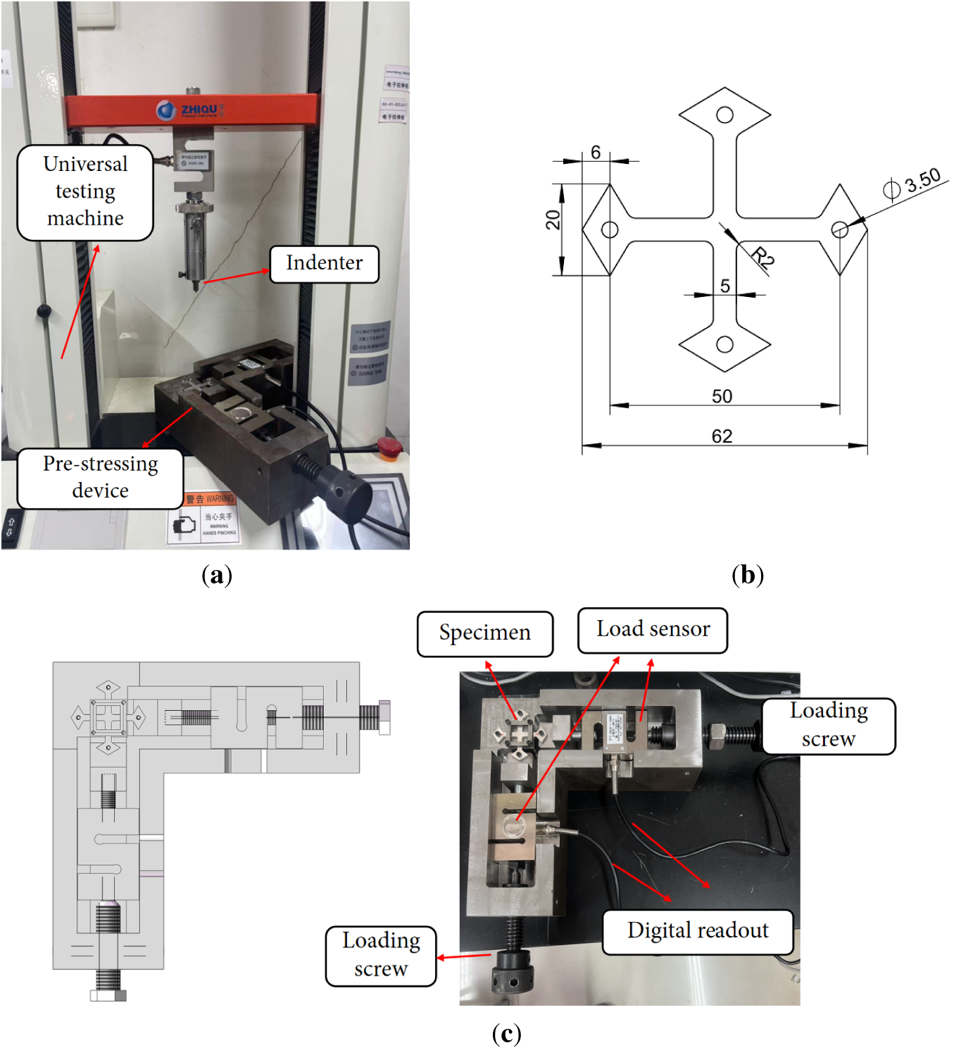
Figure 1: Spherical indentation experimental setup: (a) Overall experimental setup; (b) Specimen dimensions; (c) Pre-stressing fixture.
A 0.8 mm radius tungsten carbide sphere served as the indenter, with the target displacement restricted to 0.008 mm. This setup generated non-equibiaxial residual stresses within the intersection zone of the cruciform specimen. Indentation tests were conducted on Al 7075 alloy and 18CrNiMo7-6 alloy specimens under various stress states using a universal testing machine integrated with a contact-type displacement sensor. For each testing condition, three replicate tests were performed. Both loading and unloading rates were maintained at 0.001 mm/s, with a load holding time of 10 s.
2.1.3 X-Ray Diffraction Residual Stress Measurement
To provide a benchmark validation for the proposed indentation method, X-ray diffraction (XRD) measurements were performed on the same batch of cruciform specimens using a Proto LXRD residual stress analyzer equipped with a Cr Kα radiation source, as shown in Fig. 2. The pre-stressed cruciform specimens (Al 7075 and 18CrNiMo7-6) were fixed on a bespoke biaxial loading fixture to maintain the preset stress states throughout the entire testing process. The fixture with the specimen was placed directly under the diffractometer to ensure the test area was strictly consistent with the subsequent indentation test area. The macroscopic residual stresses in the x and z directions were calculated based on the classical sin2ψ method by collecting diffraction peaks at multiple discrete tilt angles. Each test condition was repeated three times to ensure the statistical reliability of the measurement results.
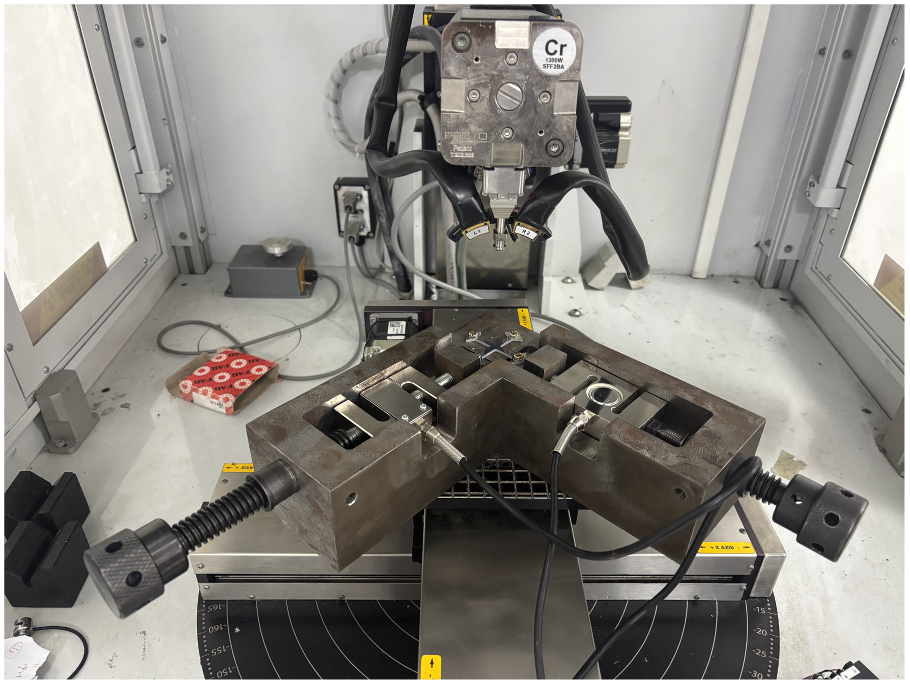
Figure 2: Experimental setup for Proto LXRD diffractometer.
Considering the characteristics of the specimen and non-equibiaxial residual stresses, a 3D quarter-symmetry FE model was developed in Abaqus, as shown in Fig. 3, to simulate the spherical indentation process. Used as the indenter was a rigid sphere with a radius of 0.8 mm. The specimen dimensions are 2 mm × 2 mm × 2 mm, with an indentation depth of 0.008 mm and a friction coefficient set at 0.15. The specimen was vertically constrained at its lower boundary, and axisymmetric restraints were imposed on the symmetry planes. All degrees of freedom for the indenter were constrained except for the y-axis, allowing it only to move upward or downward.
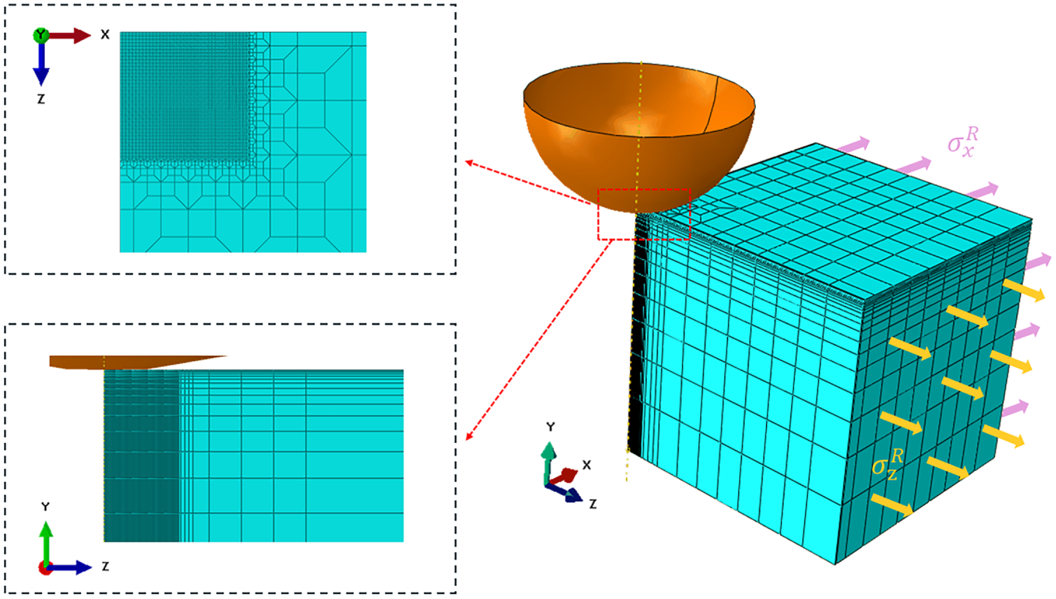
Figure 3: FE simulation model of the spherical indentation specimen under non-equibiaxial residual stress.
To balance numerical accuracy with computational cost, a locally densified mesh was implemented in the vicinity of the contact zone, and a mesh convergence study was performed. Three different minimum element sizes (0.005, 0.003, and 0.001 mm) were assigned within the intense deformation zone under the indenter tip to evaluate the stabilization of the indentation load-displacement response. As demonstrated by the P-h curves and the magnified view of the peak in Fig. 4, the relatively coarse mesh of 0.005 mm overestimates the local material stiffness, leading to mesh non-convergence. However, when the element size is refined to 0.003 mm, the curve asymptotically converges and becomes perfectly congruent with the ultra-fine 0.001 mm mesh profile. Given that the relative error in peak load between the 0.003 and 0.001 mm configurations is exceptionally small (well below 0.5%), 0.003 mm is definitively chosen as the optimal minimum element size to balance robust grid-independence with computational efficiency. C3D8R (an 8-node linear brick, reduced integration) elements were used for meshing, totaling 66,836 elements. Residual stresses were uniformly applied along the x-axes and z-axes of the specimen as initial predefined fields.
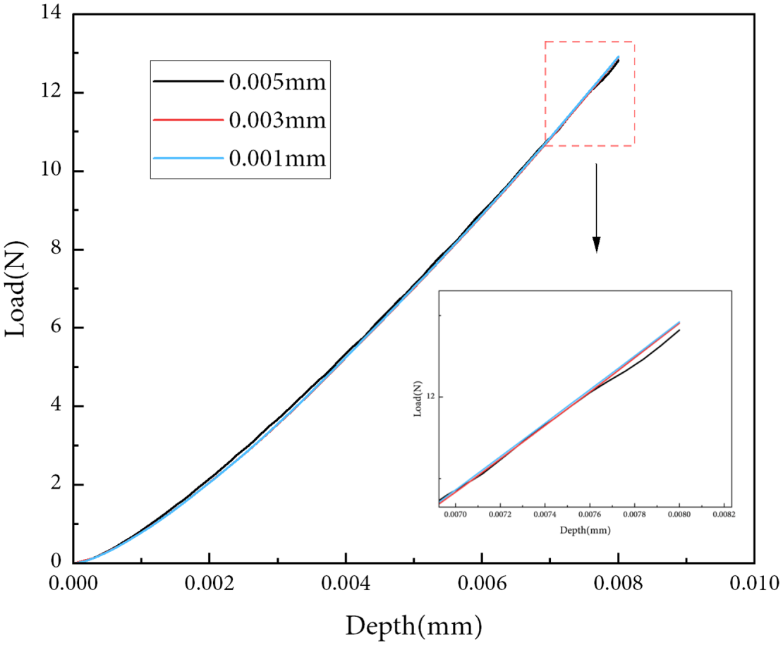
Figure 4: Mesh convergence analysis.
To conduct machine learning training, a spherical indentation simulation dataset was established, as shown in Table 1. A batch processing method was utilized for the calculations, involving 2400 FE simulations calculations performed (6 × 10 × 8 × 5 × 1 × 1).
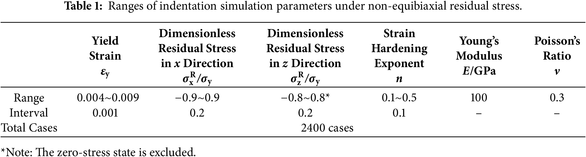
3 Dimensional Analysis and Machine Learning Models
3.1.1 Dimensional Analysis of Total Indentation Work
For the spherical indentation of a stress-free specimen, the total indentation work Wt0 shown in Fig. 5 is determined by the following parameters: the specimen’s mechanical properties, including Young’s modulus E, Poisson’s ratio ν, yield stress σy, and strain hardening exponent n; the indenter properties, including Young’s modulus Ei, Poisson’s ratio νi, and radius R; and the maximum indent hm. The total indentation work for a stress-free specimen is:
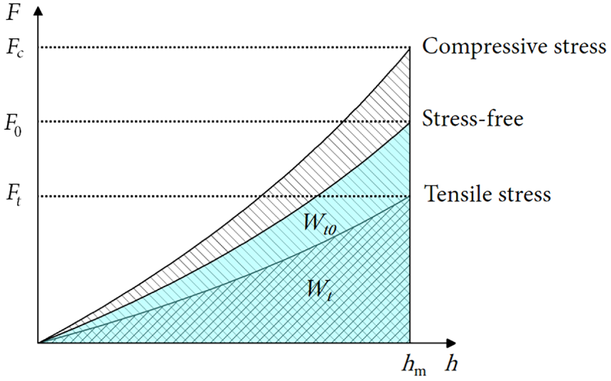
Figure 5: Schematic of total indentation work.
For the specimen with non-equibiaxial residual stresses, by introducing the orthogonal principal stress components
Since the elastic modulus of the tungsten carbide indenter greatly surpassed that of the tested material, the indenter was taken to be perfectly rigid. The ν is typically around 0.3, and its influence on the experimental results is negligible [58]. Therefore, Eqs. (1) and (2) can be simplified as:
By selecting E and R as the fundamental physical quantities, other variables with dimensions of length and force are normalized. According to the principle of dimensional homogeneity, the residual stress terms in the x and z directions are converted into dimensionless forms (
Through the aforementioned dimensional transformations, Eqs. (3) and (4) are rewritten as:
From Eqs. (5) and (6), the normalized total indentation work variation Wnorm is:
where the yield strain is εy = σy/E, and the ratio hm/R is fixed at 0.01 in this study, Eq. (7) can be further simplified as:
According to Eq. (8), Wnorm primarily depends on the plasticity parameters (εy, n) and the non-equibiaxial residual stresses (
3.1.2 Dimensional Analysis of Ellipticity
The ellipticity λ is a function of E, ν, σy, n, Ei, νi, R, hm, and the non-equibiaxial residual stresses (
As with the dimensional analysis of the total indentation work, by selecting E and R as the fundamental quantities and neglecting the influence of Ei, νi, and ν, and by adopting the forms of
Eq. (10) reduces to a simpler form by setting the normalized peak indentation depth, hm/R is taken as 0.01:
According to Eq. (11), the residual indentation ellipticity primarily depends on the plasticity parameters (εy, n) and the dimensionless non-equibiaxial residual stresses (
Through dimensional analysis, Eqs. (8) and (11) contact the non-equibiaxial residual stresses with Wnorm, λ, and the plasticity parameters of the specimen. Consequently, a mapping model between these parameters can be established, enabling the detection of non-equibiaxial residual stresses via machine learning.
3.2 Construction of Neural Networks
In this work, three different neural network frameworks were selected: ST-MLP, MLP, and DMTR based on parameter sharing. The architectures of these neural networks are illustrated in Fig. 6, and their predictive performances were compared. As shown in Fig. 6a,b, both ST-MLP and MLP consist of three types of network layers. The hidden layers can comprise multiple levels, with each level containing numerous neurons. When employing the MLP, the output layer is composed of multiple neurons, with each neuron matching a specific output, thereby addressing multiple tasks simultaneously within a single model. When each target is executed independently and the output layer contains only one neuron, the model is referred to as ST-MLP. In Fig. 6c, the DMTR is composed of four sections. The category of hidden layers encompasses both shared and task-specific (non-shared) components. The shared layers aim to extract target-agnostic representations, whereas the non-shared layers capture target-specific features. If only shared hidden layers are utilized, all parameters are shared, and the model effectively approximates an MLP.
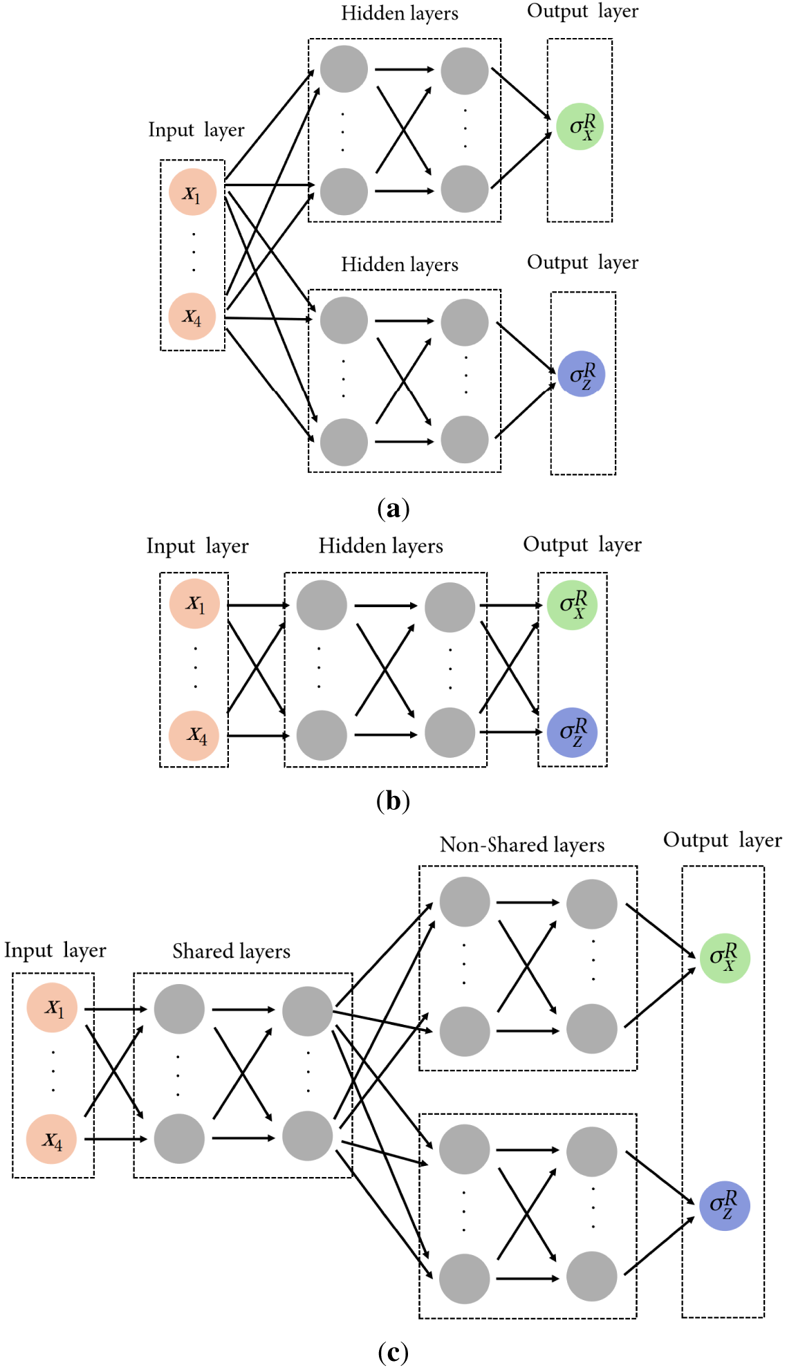
Figure 6: Three neural network architectures: (a) ST-MLP; (b) MLP; (c) DMTR.
Machine learning training was conducted on a dataset of 2400 indentation simulation cases under non-equibiaxial residual stress. The data were randomly allocated to three groups: training (70%), validation (15%), and testing (15%).
Four parameters, Wnorm, εy, n, and λ were used as input values. The two dimensionless residual stress components
Choose ReLU as the activation function, the logarithm of the hyperbolic cosine (Log-Cosh) as the loss function, and MAPE as the metric for the training of ST-MLP, MLP, and DMTR. Their expressions are as follows:
Set the batch size to 300, and the number of iterations to 3000. Optuna was employed to search for the optimal hyperparameters. The search ranges are presented in Table 2. For ST-MLP, MLP, and DMTR, the best hyperparameter combinations were identified based on the MAPE values on the validation set after 10,000 iterations of hyperparameter combinations.
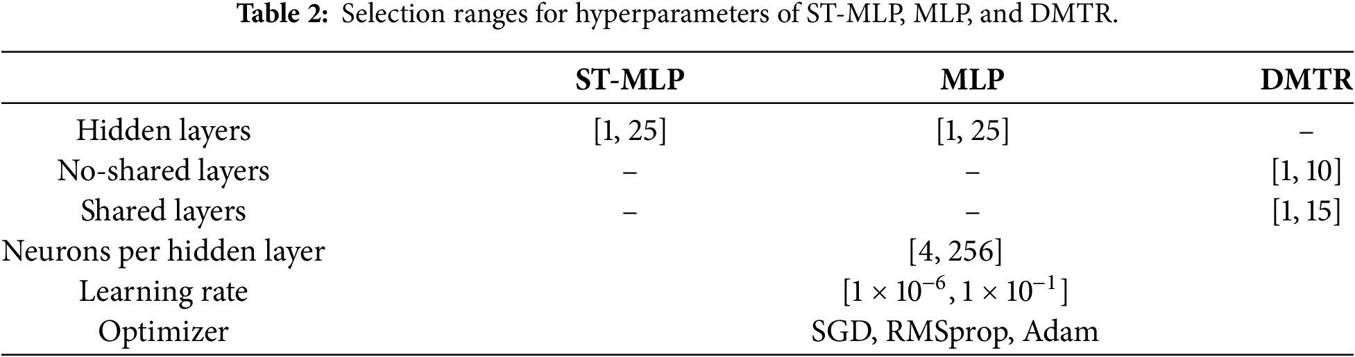
Fig. 7 illustrates the effects of εy, and n on Wnorm, and λ, as well as the influence of
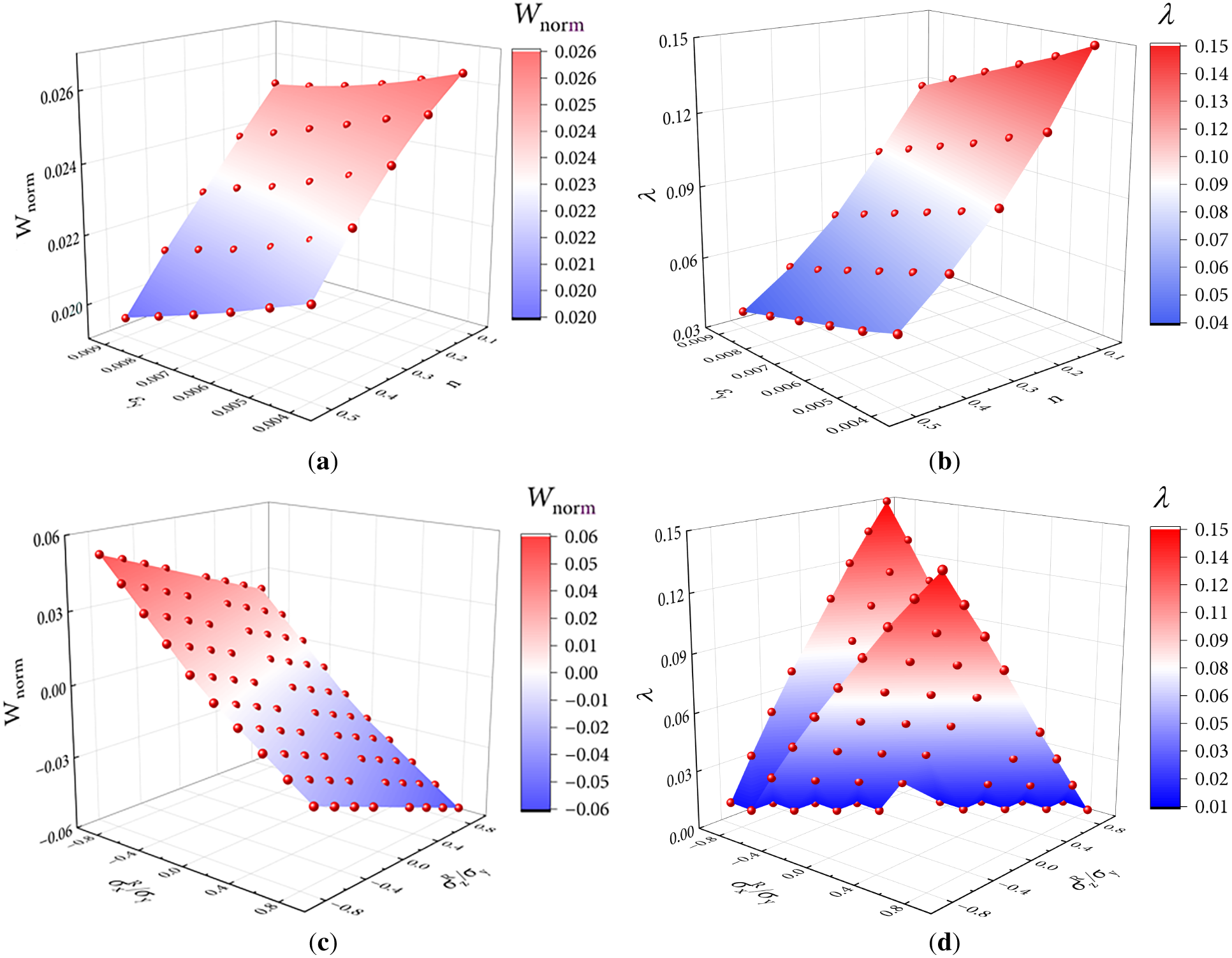
Figure 7: Effects of material parameters on total indentation work and ellipticity: (a) Effects of εy and n on Wnorm with fixed
4.2 Training Results of Machine Learning Models
Taking the DMTR as an example, the training process is shown in Fig. 8. The minimum MAPE value was achieved at the 588th iteration, with an error of 3.50% on the validation set, demonstrating a good fitting effect. Using the same method, the optimal hyperparameters for the three models were identified, and their specific combinations are presented in Table 3.
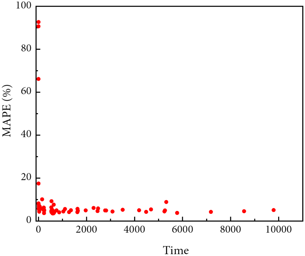
Figure 8: Variation of MAPE on the validation set during DMTR hyperparameter optimization.
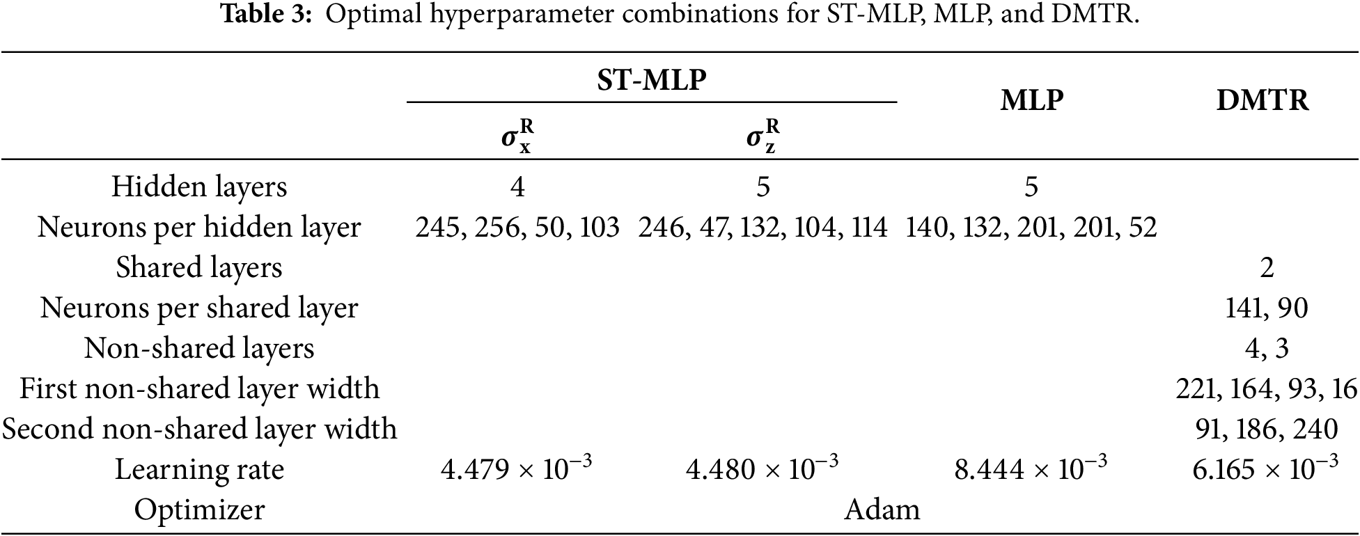
The errors of the training, validation, and testing sets for the ST-MLP, MLP, and DMTR models were calculated using FE simulations to evaluate the predictive capability of the optimal hyperparameters. According to Table 4, the DMTR model performs better in the x direction, while both ST-MLP and DMTR exhibit strong performance in the z direction. Overall, the DMTR model demonstrates the best performance.
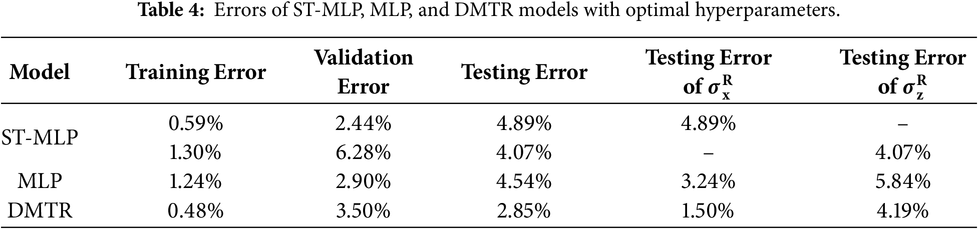
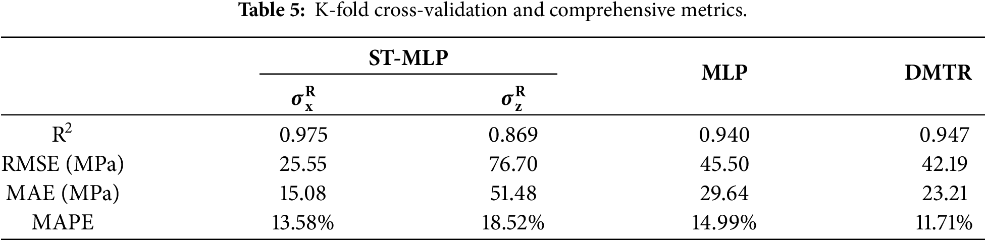
To ensure statistical robustness and eliminate potential data bias, a 5-fold cross-validation (CV) scheme was implemented. In addition to the MAPE, a comprehensive set of evaluation metrics was introduced to systematically quantify the prediction accuracy, including the Coefficient of Determination (R2), Root Mean Square Error (RMSE), and Mean Absolute Error (MAE). Table 5 compares the average 5-fold CV results across different network architectures, demonstrating that the developed DMTR model achieves superior accuracy and stability with extremely narrow standard deviation bands.
Furthermore, to explicitly eliminate concerns regarding potential overfitting, the learning curves representing the training vs. validation loss (LogCosh) convergence history were closely monitored up to 3000 epochs, as illustrated in Fig. 9. Both the training and validation losses exhibit a rapid, synchronized initial descent and subsequently stabilize asymptotically. The validation loss strictly tracks the training loss throughout the entire training process without any divergence, firmly confirming that the trained model possesses excellent generalization capability and is free from overfitting.
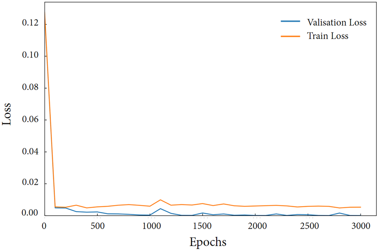
Figure 9: Training curve of the DMTR model.
Further analysis was conducted on the error distributions of the three models on the testing set, as illustrated in Fig. 10. A contrast between the three models reveals that, for the prediction of
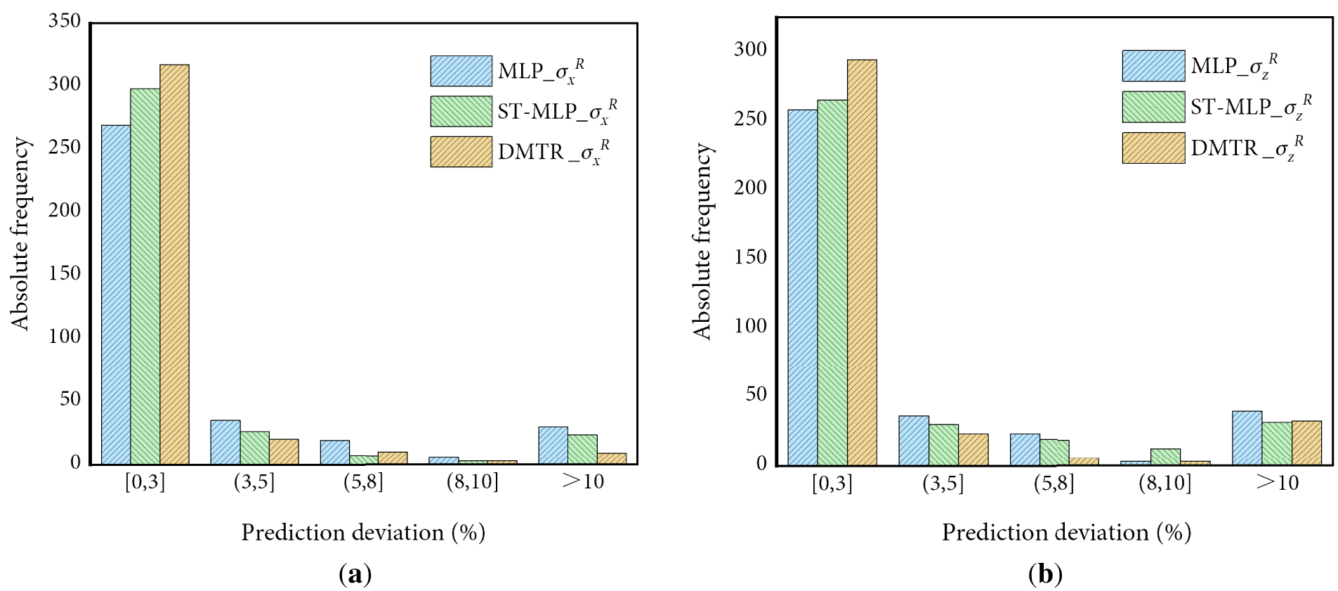
Figure 10: Error distributions of ST-MLP, MLP, and DMTR on the testing set: (a)
To unlock the “black-box” nature of the data-driven framework and verify its physical consistency, model interpretability was established utilizing the SHAP (SHapley Additive exPlanations) approach. Fig. 11 displays the SHAP summary plots, which quantify the global feature importance and the corresponding directional effects of input variables on the target outputs. It is evident that Wnorm and εy emerge as the most decisive features governing the model’s predictions. This hierarchical importance perfectly aligns with classical elastoplastic contact mechanics, where the energy dissipation during the loading-unloading cycle and the elastic-plastic transition threshold predominantly dictate the indentation response under residual stress fields. Consequently, the SHAP analysis successfully provides a robust physical foundation for the neural network, bridging the gap between data-driven mapping and empirical contact mechanics.
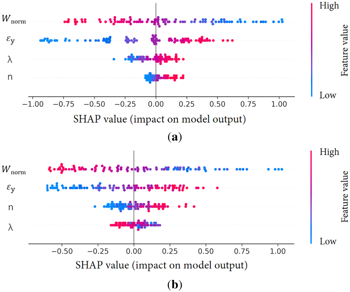
Figure 11: SHapley Additive exPlanations analysis: (a)
To verify the effectiveness of the machine learning approach, both FE validation and experimental validation methods were employed to validate the prediction results of the neural network model.
Additional indentation FE simulations were conducted in ABAQUS for three specific materials: Al 7075, Al 2024, and Ti Grade 5. The input material parameters, obtained from Reference [40], are listed in Table 6, with different residual stresses randomly assigned to each material. Upon completion of the simulations, the ellipticity of the residual indentation and the total indentation work can be measured from the residual indentation morphology and the P-h curves, respectively.

The Wnorm, εy, n, and λ of the three materials were input into the ST-MLP, MLP, and DMTR models to predict
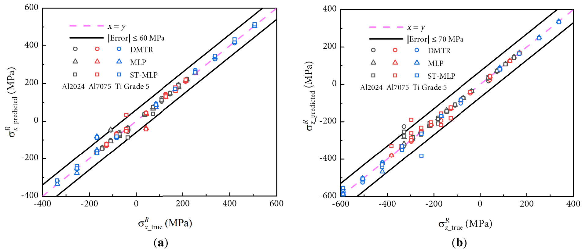
Figure 12: Machine learning predictions for non-equibiaxial residual stresses: (a)
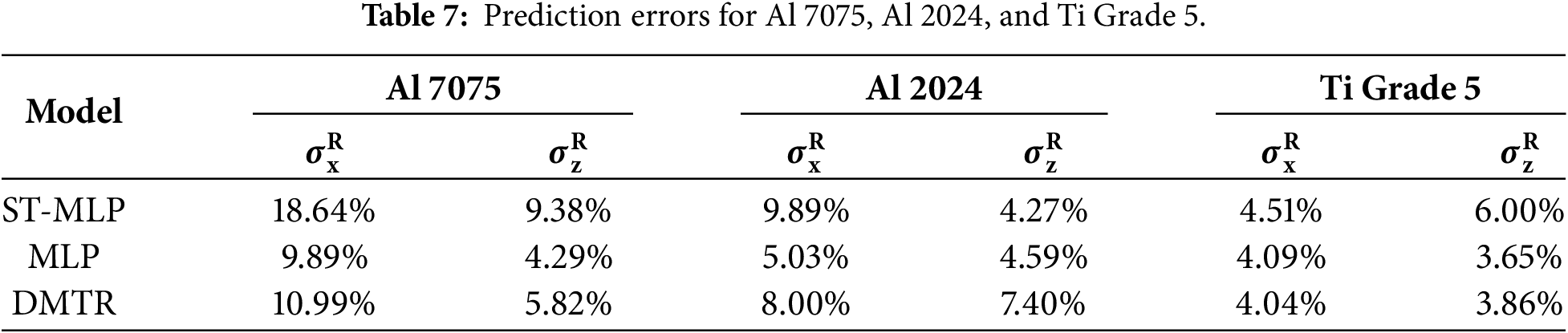
Among the three neural network models, both MLP and DMTR exhibit excellent predictive performance. Combined with the training results, the DMTR model demonstrates superior performance. Its architecture, which integrates shared and non-shared layers, effectively extracts common features while learning task-specific characteristics, thereby enhancing the model’s learning capacity and generalization. On the testing set, the DMTR achieved the lowest prediction error (MAPE = 2.85%) with a more concentrated error distribution. Furthermore, it maintained a solid performance with errors less than 11% in the predictions for Al 7075, Al 2024, and Ti Grade 5, verifying its reliability and applicability.
4.4.1 Uniaxial Tensile Test Results
The true stress-strain curves of the material were obtained through uniaxial tensile tests, in Fig. 13. Based on these curves, the power-law hardening constitutive model parameters and the elastic modulus were fitted. For Al 7075, the E is 70.29 ± 3.14 GPa, the σy is 505.23 ± 11.52 MPa, and the n is 0.09 ± 0.002. For 18CrNiMo7-6, the E is 198.41 ± 3.72 GPa, the σy is 455.15 ± 12.96 MPa, and the n is 0.12 ± 0.002.
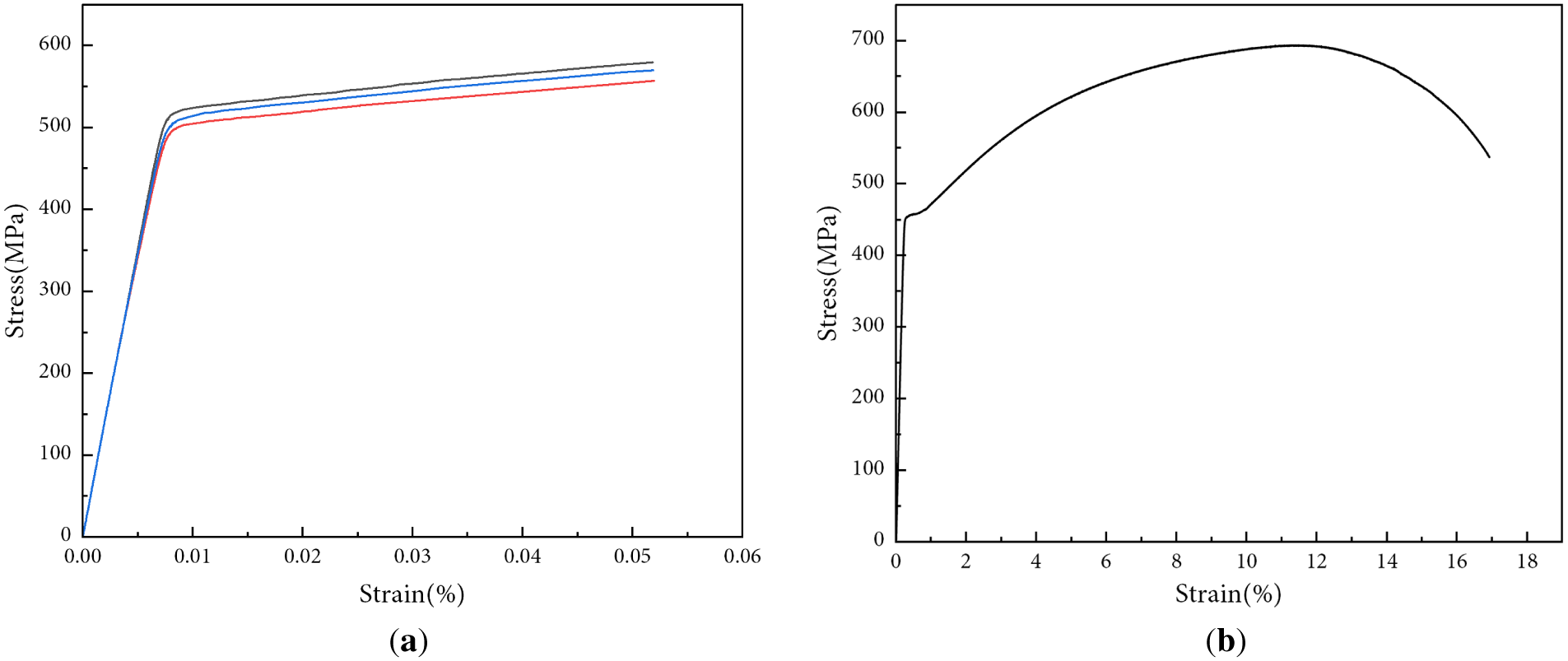
Figure 13: True stress-strain curves from tensile tests: (a) Al 7075; (b) 18CrNiMo7-6.
4.4.2 Spherical Indentation Test Results and Validation
Fig. 14 shows the P-h curves and a typical indentation morphology from the spherical indentation tests. Fig. 14a,b respectively shows the P-h curves of Al 7075 and 18CrNiMo7-6. In Fig. 14a, the rate of load increase with indentation depth for the unstressed specimen is faster than that for the tensile-stressed specimen. This suggests that residual tensile stress reduces the bearing capacity of the material under indentation. For the compressive-stressed specimen (
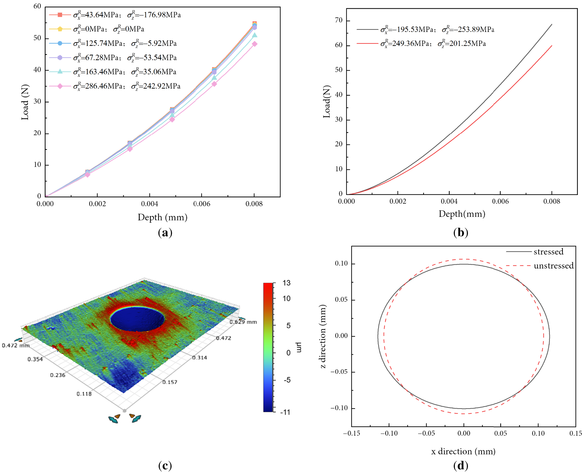
Figure 14: Experimental results: (a) P-h curves under different conditions of Al 7075; (b) P-h curves under different conditions of 18CrNiMo7-6; (c) 3D morphology of the indentation; (d) Indentation characteristics in the x and z directions.
Given the preceding analysis, the DMTR model demonstrates stable predictive performance for non-equibiaxial residual stresses. Taking the total indentation work, yield strain, strain hardening exponent, and residual morphology ellipticity from the indentation tests as input data, the prediction results are presented in Table 8. It is evident that the predicted values of
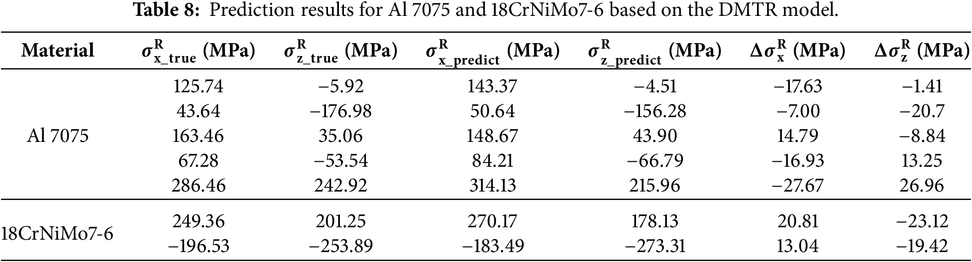
The XRD measurement results under different pre-stress conditions are summarized in Table 9. It can be observed that the measurement errors of the XRD method are within 35 MPa for both materials, with standard deviations ranging from ±12.45 to ±37.70 MPa. In comparison, the DMTR model proposed in this work achieves a prediction error within 30 MPa, exhibiting better accuracy and stability than the conventional XRD method, which further validates the reliability of the proposed indentation method.

The validation of non-equibiaxial residual stresses in Al 7075 alloy and 18CrNiMo7-6 alloy confirms the feasibility of the “single spherical indentation + DMTR model” approach for stress detection. This work achieves dual-axis stress measurement through a single indentation. Compared to the Knoop indentation scheme requiring four rotations, this method significantly enhances detection efficiency and minimizes material damage while maintaining high precision. Furthermore, by integrating both Wnorm and λ, the proposed method offers a more comprehensive characterization of the stress state than traditional approaches using only a single load curve or morphological feature. This spherical indentation method acquires two stress components simultaneously in one step, making it user-friendly, minimally invasive, and ideal for rapid on-site testing. The sensitivity and ease of measurement of the residual indentation ellipticity and the change rate of total indentation work provide stable and robust input features for the machine learning model.
Overall, the DMTR model, with its architecture combining shared and non-shared layers, effectively learns both common information and task-specific characteristics from input features, thereby surpassing traditional MLP and ST-MLP models in predictive accuracy. This finding corroborates the conclusions of Zhang et al. [51] regarding the superior performance of DMTR in scratch tests, indicating that the parameter-sharing mechanism offers universal advantages in multi-output mechanical inversion problems.
Although the methodology proposed in this study performs well in characterizing non-equibiaxial stress states, the framework assumes a localized uniformity of the stress field, meaning that the steep residual stress gradients along the depth profile may introduce prediction errors. Furthermore, the model is constructed based on macro continuum mechanics principles, without explicitly accounting for the heterogeneity of localized microstructures. Therefore, rigorous validation remains necessary for scenarios that exceed the predefined parameter ranges. Precision is also constrained by physical idealizations including the continuum constitutive law and ideal indenter shape, alongside experimental factors such as equipment alignment and surface conditions. To this end, subsequent research could focus on constructing more extensive multi-material and multi-stress databases to enhance model universality and exploring in-situ online monitoring technologies integrated with multi-modal information fusion to further expand the applicability and reliability of this method in complex engineering service environments. Further, upcoming works will combine indentation with micro-focused miniature hole-drilling coupled with digital image correlation (DIC), and SEM/EBSD characterization to evaluate residual stresses.
In this work, a residual stress detection method that integrates spherical indentation technology with deep learning algorithms is proposed. This method enables accurate modeling of the mapping relationship between indentation responses and non-equibiaxial residual stresses. The main results are as follows:
(1) The training and validation errors of the ST-MLP, MLP, and DMTR models are all within 7%, and their prediction errors for the MLP and DMTR are all less than 11%.
(2) In the experimental validation, the DMTR model achieves a residual stress prediction error below 30 MPa on Al 7075 and 18CrNiMo7-6, demonstrating superior predictive accuracy and robust generalization capability.
Acknowledgement: Not applicable.
Funding Statement: The authors disclosed receipt of the following financial support for the research, authorship, and/or publication of this article: This work was supported by the National Natural Science Foundation of China [Grant Nos. 12072324 and 12432004]; and the Important Science & Technology Specific Projects of Henan Province [Grant No. 201400211200]; MIIT High-quality Development Special Project [2023ZY01019-06].
Author Contributions: Conceptualization, methodology, reviewing, Jianwei Zhang; data curation, writing—original draft preparation, Ran Shen; writing—review and editing, Yuanxin Li; visualization, Qianqi Zhang and Shengchao Chen; writing—editing, Minghao Zhao; investigation, Lubing Shi; software, Bing Wang. All authors reviewed and approved the final version of the manuscript.
Availability of Data and Materials: The complete source code, along with relevant datasets and documentation, is available from the corresponding authors upon reasonable request.
Ethics Approval: Ethical approval was not required for this study, as it is based solely on the analysis and synthesis of previously published research and does not involve human subjects, animal experiments, or identifiable personal data.
Conflicts of Interest: The authors declare no conflicts of interest.
Abbreviations
The following abbreviations are used in this manuscript:
| FE | Finite element |
| ST-MLP | The single-target approach |
| MLP | The classical multi-output multi-layer perceptron |
| DMTR | The parameter sharing-based deep network |
| P-h | The load-depth curves |
References
1. Withers PJ. Residual stress and its role in failure. Rep Prog Phys. 2007;70(12):2211. doi:10.1088/0034-4885/70/12/R04. [Google Scholar] [CrossRef]
2. Withers PJ, Bhadeshia HKDH. Residual stress. Part 1—measurement techniques. Mater Sci Technol. 2001;17(4):355–65. doi:10.1179/026708301101509980. [Google Scholar] [CrossRef]
3. Suresh S, Giannakopoulos AE. A new method for estimating residual stresses by instrumented sharp indentation. Acta Mater. 1998;46(16):5755–67. doi:10.1016/S1359-6454(98)00226-2. [Google Scholar] [CrossRef]
4. Baldi A. A new analytical approach for hole drilling residual stress analysis by full field method. J Eng Mater Technol. 2005;127(2):165–9. doi:10.1115/1.1839211. [Google Scholar] [CrossRef]
5. Luo J. Non-destructive evaluation of residual stress. Mech Eng. 2003;4:6–11. (In Chinese). [Google Scholar]
6. Peng GJ, Zhang TH. Progress in instrumented indentation methods for determination of surface residual stress. Chin J Theor Appl Mech. 2022;54(8):2287–303. (In Chinese). doi:10.6052/0459-1879-22-222. [Google Scholar] [CrossRef]
7. Olson MD, DeWald AT, Hill MR. An uncertainty estimator for slitting method residual stress measurements including the influence of regularization. Exp Mech. 2020;60(1):65–79. doi:10.1007/s11340-019-00535-x. [Google Scholar] [CrossRef]
8. Schajer GS. Universal calibration constants for strain gauge hole-drilling residual stress measurements. Exp Mech. 2022;62(2):351–8. doi:10.1007/s11340-021-00771-0. [Google Scholar] [CrossRef]
9. Chen S, En YF, Li GY, Wang ZZ, Gao R, Ma R, et al. An ion beam layer removal method of determining the residual stress in the as-fabricated TSV-Cu/TiW/SiO2/Si interface on a nanoscale. Microelectron Reliab. 2020;112(1):113826. doi:10.1016/j.microrel.2020.113826. [Google Scholar] [CrossRef]
10. Ghaedamini R, Ghassemi A, Atrian A. A comparative experimental study for determination of residual stress in laminated composites using ring core, incremental hole drilling, and slitting methods. Mater Res Express. 2019;6(2):025205. doi:10.1088/2053-1591/aaee46. [Google Scholar] [CrossRef]
11. Lodh A, Thool K, Samajdar I. X-ray diffraction for the determination of residual stress of crystalline material: an overview. Trans Indian Inst Met. 2022;75(4):983–95. doi:10.1007/s12666-022-02540-6. [Google Scholar] [CrossRef]
12. Dong H, Liu X, Song Y, Wang B, Chen S, He C. Quantitative evaluation of residual stress and surface hardness in deep drawn parts based on magnetic Barkhausen noise technology. Measurement. 2021;168(3):108473. doi:10.1016/j.measurement.2020.108473. [Google Scholar] [CrossRef]
13. Acevedo R, Sedlak P, Kolman R, Fredel M. Residual stress analysis of additive manufacturing of metallic parts using ultrasonic waves: state of the art review. J Mater Res Technol. 2020;9(4):9457–77. doi:10.1016/j.jmrt.2020.05.092. [Google Scholar] [CrossRef]
14. Faisal NH, Ahmed R, Prathuru AK, Paradowska A, Lee TL. Measuring residual strain and stress in thermal spray coatings using neutron diffractometers. Exp Mech. 2022;62(3):369–92. doi:10.1007/s11340-021-00803-9. [Google Scholar] [CrossRef]
15. Bolshakov A, Oliver WC, Pharr GM. Influences of stress on the measurement of mechanical properties using nanoindentation: part II. Finite Element Simulations J Mater Res. 1996;11(3):760–8. doi:10.1557/JMR.1996.0092. [Google Scholar] [CrossRef]
16. Bolshakov A, Pharr GM. Influences of pileup on the measurement of mechanical properties by load and depth sensing indentation techniques. J Mater Res. 1998;13(4):1049–58. doi:10.1557/JMR.1998.0146. [Google Scholar] [CrossRef]
17. Field JS, Swain MV. A simple predictive model for spherical indentation. J Mater Res. 1993;8(2):297–306. doi:10.1557/JMR.1993.0297. [Google Scholar] [CrossRef]
18. Chen X, Yan J, Karlsson AM. On the determination of residual stress and mechanical properties by indentation. Mater Sci Eng A. 2006;416(1–2):139–49. doi:10.1016/j.msea.2005.10.034. [Google Scholar] [CrossRef]
19. Peng G, Zhang T, Feng Y, Huan Y. Determination of shear creep compliance of linear viscoelastic-plastic solids by instrumented indentation. Polym Test. 2012;31(8):1038–44. doi:10.1016/j.polymertesting.2012.07.007. [Google Scholar] [CrossRef]
20. Sun Y, Peng G, Hu Y, Dou G, Chen P, Zhang T. Spherical indentation model for evaluating the elastic properties of the shell of microsphere with core-shell structure. Int J Solids Struct. 2021;230–231(11):111159. doi:10.1016/j.ijsolstr.2021.111159. [Google Scholar] [CrossRef]
21. Zhang T, Yu C, Peng G, Feng Y. Identification of the elastic–plastic constitutive model for measuring mechanical properties of metals by instrumented spherical indentation test. MRS Commun. 2017;7(2):221–8. doi:10.1557/mrc.2017.28. [Google Scholar] [CrossRef]
22. Oliver WC, Pharr GM. An improved technique for determining hardness and elastic modulus using load and displacement sensing indentation experiments. J Mater Res. 1992;7(6):1564–83. doi:10.1557/JMR.1992.1564. [Google Scholar] [CrossRef]
23. Xu G, Luo J, Lu F, Wang G, Liu H, Zhao M. Characterization of fracture toughness for surface-modified layer of 18CrNiMo7-6 alloy steel after carburizing heat treatment by indentation method. Eng Fract Mech. 2022;269(4):108508. doi:10.1016/j.engfracmech.2022.108508. [Google Scholar] [CrossRef]
24. Anstis GR, Chantikul P, Lawn BR, Marshall DB. A critical evaluation of indentation techniques for measuring fracture toughness: I, direct crack measurements. J Am Ceram Soc. 1981;64(9):533–8. doi:10.1111/j.1151-2916.1981.tb10320.x. [Google Scholar] [CrossRef]
25. Yu F, Fang J, Omacht D, Sun M, Li Y. A new instrumented spherical indentation test methodology to determine fracture toughness of high strength steels. Theor Appl Fract Mech. 2023;124(4):103744. doi:10.1016/j.tafmec.2022.103744. [Google Scholar] [CrossRef]
26. Jang JI. Estimation of residual stress by instrumented indentation: a review. J Ceram Process Res. 2009;10(3):391–400. doi:10.36410/jcpr.2009.10.3.391. [Google Scholar] [CrossRef]
27. Tsui TY, Oliver WC, Pharr GM. Influences of stress on the measurement of mechanical properties using nanoindentation: part I. Experimental studies in an aluminum alloy. J Mater Res. 1996;11(3):752–9. doi:10.1557/JMR.1996.0091. [Google Scholar] [CrossRef]
28. Wang Z, Zhang M, Li M, Li X, Li L, Zhao H. Micromechanical properties and deformation damage behaviors of SiCp/Al composites using cryogenic indentation technique. J Mater Res Technol. 2026;40(2):707–17. doi:10.1016/j.jmrt.2025.12.190. [Google Scholar] [CrossRef]
29. Wang Z, Li L, Zhang Z, Ji W, Li M, Zong X, et al. Investigation on indentation scaling relationships of ITO thin films considering the indenter tip rounding defect. Mater Des. 2025;259:114818. doi:10.1016/j.matdes.2025.114818. [Google Scholar] [CrossRef]
30. Han JH, Lee JS, Lee YH, Choi MJ, Lee GJ, Kim KH, et al. Residual stress estimation with identification of stress directionality using instrumented indentation technique. Key Eng Mater. 2007;345–346:1125–8. doi:10.4028/www.scientific.net/kem.345-346.1125. [Google Scholar] [CrossRef]
31. Choi MJ, Kang SK, Kang I, Kwon D. Evaluation of nonequibiaxial residual stress using Knoop indenter. J Mater Res. 2012;27(1):121–5. doi:10.1557/jmr.2011.335. [Google Scholar] [CrossRef]
32. Rickhey F, Lee JH, Lee H. A contact size-independent approach to the estimation of biaxial residual stresses by Knoop indentation. Mater Des. 2015;84:300–12. doi:10.1016/j.matdes.2015.06.119. [Google Scholar] [CrossRef]
33. Kim YC, Choi MJ, Kwon D, Kim JY. Estimation of principal directions of bi-axial residual stress using instrumented Knoop indentation testing. Met Mater Int. 2015;21(5):850–6. doi:10.1007/s12540-015-5176-1. [Google Scholar] [CrossRef]
34. Kim YC, Ahn HJ, Kwon D, Kim JY. Modeling and experimental verification for non-equibiaxial residual stress evaluated by Knoop indentations. Met Mater Int. 2016;22(1):12–9. doi:10.1007/s12540-015-5515-2. [Google Scholar] [CrossRef]
35. Carlsson S, Larsson PL. On the determination of residual stress and strain fields by sharp indentation testing. Part I: theoretical and numerical analysis. Acta Mater. 2001;49(12):2179–91. doi:10.1016/S1359-6454(01)00122-7. [Google Scholar] [CrossRef]
36. Ahn HJ, Kim JH, Xu H, Lee J, Kim JY, Kim YC, et al. Directionality of residual stress evaluated by instrumented indentation testing using wedge indenter. Met Mater Int. 2017;23(3):465–72. doi:10.1007/s12540-017-6573-4. [Google Scholar] [CrossRef]
37. Lee YH, Kwon D. Measurement of residual-stress effect by nanoindentation on elastically strained (100) W. Scr Mater. 2003;49(5):459–65. doi:10.1016/S1359-6462(03)00290-2. [Google Scholar] [CrossRef]
38. Shen L, He Y, Liu D, Gong Q, Zhang B, Lei J. A novel method for determining surface residual stress components and their directions in spherical indentation. J Mater Res. 2015;30(8):1078–89. doi:10.1557/jmr.2015.87. [Google Scholar] [CrossRef]
39. He X, Shao J, Feng J. Finite element simulation of residual stress determination based on spherical indentation accumulation morphology. World J Mech. 2021;11(6):111–20. doi:10.4236/wjm.2021.116009. [Google Scholar] [CrossRef]
40. Zhang T, Cheng W, Peng G, Ma Y, Jiang W, Hu J, et al. Numerical investigation of spherical indentation on elastic-power-law strain-hardening solids with non-equibiaxial residual stresses. MRS Commun. 2019;9(1):360–9. doi:10.1557/mrc.2018.240. [Google Scholar] [CrossRef]
41. Peng G, Xu F, Chen J, Wang H, Hu J, Zhang T. Evaluation of non-equibiaxial residual stresses in metallic materials via instrumented spherical indentation. Metals. 2020;10(4):440. doi:10.3390/met10040440. [Google Scholar] [CrossRef]
42. Jordan MI, Mitchell TM. Machine learning: trends, perspectives, and prospects. Science. 2015;349(6245):255–60. doi:10.1126/science.aaa8415. [Google Scholar] [CrossRef]
43. Zhou T, Song Z, Sundmacher K. Big data creates new opportunities for materials research: a review on methods and applications of machine learning for materials design. Engineering. 2019;5(6):1017–26. doi:10.1016/j.eng.2019.02.011. [Google Scholar] [CrossRef]
44. Wu B, Qi Y, Fu G. Optimizing convolutional neural network-long short-term memory architecture with additive attention mechanism for Stock Price Prediction. RIMNI. 2025;41(1):1–21. doi:10.23967/j.rimni.2024.10.56790. [Google Scholar] [CrossRef]
45. Chellam J, Mansingh B, Alex D, Binoj J. Prediction and validation of mechanical properties of Areca catechu/Tamarindus indica fruit fiber with nano coconut shell powder reinforced hybrid composites. J Polym Mater. 2025;42(3):773–94. doi:10.32604/jpm.2025.069295. [Google Scholar] [CrossRef]
46. Peng W, Jiang W, Yang B, Sun G, Shao X. An indentation method for measuring welding residual stress: estimation of stress-free indentation curve using BP neural network prediction model. Int J Press Vessels Pip. 2023;206(2):105070. doi:10.1016/j.ijpvp.2023.105070. [Google Scholar] [CrossRef]
47. Qin J, Zhang J, Li Y, Cao X, Qiao Z. Prediction of scratch responses of metallic material based on machine learning. Tribology. 2023;43(12):1445–52. (In Chinese). doi:10.16078/j.tribology.2022203. [Google Scholar] [CrossRef]
48. Sun T, Zhang J, Qin J, Zhao S, Li Y. Determining the elastic modulus of film/substrate materials from instrumented indentation testing based on machine learning. Sci Sin-Phys Mech Astron. 2023;53(1):214607. doi:10.1360/sspma-2022-0386. [Google Scholar] [CrossRef]
49. Manan A, Zhang P, Ahmad S, Ahmad J. Optimizing hybrid fibre-reinforced polymer bars design: a machine learning approach. J Polym Mater. 2024;41(1):15–44. doi:10.32604/jpm.2024.053859. [Google Scholar] [CrossRef]
50. Peng T, Sun T, Li Y, Wang B, Zhang J. Correlation between scratch hardness and plastic parameters of metallic materials: a comparative study of machine learning and empirical solution. J Mater Res. 2025;40(4):572–84. doi:10.1557/s43578-025-01518-6. [Google Scholar] [CrossRef]
51. Zhang J, Qin J, Li Y, Lu C, Liu H, Zhao M. Extraction of the plastic properties of metallic materials from scratch tests using deep learning. Mech Mater. 2022;175:104502. doi:10.1016/j.mechmat.2022.104502. [Google Scholar] [CrossRef]
52. Tong X, Wang B. The segmentation of debris flow fans based on spatial coordinate attention mechanism. RIMNI. 2024;40(3):9. doi:10.32604/rimni.2024.056508. [Google Scholar] [CrossRef]
53. Shin W, Baek N. A solar irradiance prediction model with recurrent neural networks and computer graphics methods. RIMNI. 2024;40(4):52. doi:10.23967/j.rimni.2025.10.58701. [Google Scholar] [CrossRef]
54. Salmani Ghanbari S, Mahmoudi AH. An improvement in data interpretation to estimate residual stresses and mechanical properties using instrumented indentation: a comparison between machine learning and Kriging model. Eng Appl Artif Intell. 2022;114(2):105186. doi:10.1016/j.engappai.2022.105186. [Google Scholar] [CrossRef]
55. Park M, Chung D, Woo W, Oh S, Jeong K, Han HN. Indentation-informed convolutional neural network for simultaneous prediction of non-equibiaxial residual stress and plastic flow. Int J Plast. 2026;197:104606. doi:10.1016/j.ijplas.2025.104606. [Google Scholar] [CrossRef]
56. Li L, Li H, Yang S, Wang Z. Evaluation of equibiaxial residual stress in metal materials using indentation testing techniques. Mater Today Commun. 2025;42(13):111268. doi:10.1016/j.mtcomm.2024.111268. [Google Scholar] [CrossRef]
57. Moon S, Choi M, Hong S, Kim SW, Yoon M. Non-equibiaxial residual stress evaluation methodology using simulated indentation behavior and machine learning. Nucl Eng Technol. 2024;56(4):1347–56. doi:10.1016/j.net.2023.11.039. [Google Scholar] [CrossRef]
58. Zhang T. Micro/nano mechanical testing techniques: measurement, analysis, application and standardization of instrumented indentation. Beijing, China: Science Press; 2013. (In Chinese). [Google Scholar]
Cite This Article
 Copyright © 2026 The Author(s). Published by Tech Science Press.
This work is licensed under a Creative Commons Attribution 4.0 International License , which permits unrestricted use, distribution, and reproduction in any medium, provided the original work is properly cited.
 Downloads
 Citation Tools
