
 Login
Login Register
 Submit a Paper
 Propose a Special lssue
 Open Access
ARTICLE
From Virtual Anchoring to High-Precision Station-Keeping: A Dynamic Virtual Guide-Point Strategy for Underactuated USVs
1 Fuzhou Institute of Oceanography, Minjiang University, Fuzhou, China
2 State Key Laboratory of Maritime Technology and Safety, Wuhan University of Technology, Wuhan, China
3 College of Physics and Electronic Information Engineering, Minjiang University, Fuzhou, China
* Corresponding Author: Zihe Qin. Email:
Computers, Materials & Continua 2026, 89(2), 34 https://doi.org/10.32604/cmc.2026.086097
Received 24 May 2026; Accepted 24 July 2026; Issue published 15 September 2026
 View Full Text
 Download PDF
Abstract
To address the challenge of precise station-keeping for underactuated unmanned surface vehicles (USVs) in unknown current environments, our team previously proposed a solution based on a “virtual anchoring” method. However, field tests revealed that the inherent “virtual anchor line” constraint limits positioning accuracy. This work introduces a novel control strategy to overcome the aforementioned issue, which enables accurate unmanned surface vehicle (USV) station-keeping by significantly reducing the distance constraint inherent to traditional virtual anchoring. The core innovation lies in a Dynamic Virtual Guide-Point, whose position is updated based on a real-time estimate of the current direction. The current direction is approximated in real time using a discrete low-pass filter, which provides smooth tracking of the instantaneous flow-direction observation. Subsequently, a controller is designed based on Lyapunov theory to drive the USVs to track this dynamic point. Numerical simulations demonstrate that, compared to the conventional virtual anchoring method, the proposed approach achieves effective hovering at the target with a substantial reduction in positional error. The controller also exhibits strong robustness against variations in current and external disturbances. The proposed Dynamic Virtual Guide-Point (DVP)-based strategy effectively mitigates the limitations of the original method, enabling true “point-keeping” rather than “arc-keeping”, thereby enhancing the USV’s capability to perform precise maritime operations.Keywords
As a key component of mobile marine platforms, unmanned surface vehicles (USVs) have attracted significant attention due to their flexibility, cost-effectiveness, and suitability for high-risk missions [1]. With the continuous expansion of application scenarios, the functional requirements for USVs have evolved beyond basic transit and navigation to include missions that demand high-precision station-keeping in dynamic marine environments [2]. For example, in applications such as fixed-point hydrological observation [3] and deployment and recovery of underwater equipment [4], precise and stable hovering capability is essential for mission success. This capability directly reflects a USV’s level of autonomous control and environmental adaptability, and has become a core metric for evaluating its intelligence and capacity to execute complex maritime tasks.
Existing research on dynamic positioning (DP) has established a relatively comprehensive theoretical system for vessels or USVs equipped with redundant propulsion systems. However, due to cost and size constraints, most small and medium-sized USVs are typically equipped with only a single propeller and rudder, making them underactuated platforms. Traditional DP methods that assume full actuation are difficult to apply directly. Moreover, even among the limited studies addressing underactuated unmanned surface vehicle (USV) station-keeping, existing approaches exhibit inherent limitations: path-following-based methods require continuous propulsion operation, leading to high energy consumption [5], whereas virtual anchor-based strategies are constrained by fixed geometric configurations that prevent true point-keeping at the target. Therefore, designing a station-keeping control method for conventional underactuated USVs—one that does not rely on propeller redundancy, yet achieves high precision and high energy efficiency, and maintains strong robustness against unknown time-varying disturbances—remains an open and challenging problem.
Precise station-keeping of vessels and USVs in dynamic marine environments is essentially a dynamic positioning (DP) control problem. Existing DP research has established a relatively mature theoretical system. In the following, we review the state of the art from the perspectives of observer techniques, nonlinear control, model predictive control, data-driven methods, and the DP challenges specific to underactuated USVs, in order to identify the research gaps that motivate this study.
The key challenge in DP systems lies in the accurate estimation and effective rejection of unknown, time-varying environmental disturbances from wind, waves, and currents. Disturbance observer (DO)-based control has become a mainstream framework to address this challenge. Du et al. [6] constructed a disturbance observer to handle unknown time-varying disturbances and employed adaptive vectorial backstepping, achieving globally asymptotic regulation of positioning errors. Yu et al. [7] proposed a composite anti-disturbance control strategy integrating a stochastic disturbance observer, adaptive techniques, and robust control terms. For unmeasured states, Fu et al. [8] proposed a finite-time extended state observer that simultaneously estimates unmeasured states, unknown model parameters, and time-varying disturbances. Liu et al. [9] introduced a sliding mode disturbance observer with a unified barrier function to keep the vessel within safety boundaries. These observer-based methods have significantly improved DP accuracy and robustness; however, most rely on the assumption that the vessel is fully actuated, and the observers are typically designed based on the vessel’s kinetic model structure, which limits their applicability when model information is unreliable.
In terms of controller design, backstepping combined with disturbance observers is one of the most widely adopted frameworks. Hu et al. [10] and Tomera and Podgórski [11] both employed DO-based backstepping, achieving globally asymptotic convergence of positioning error and demonstrating superior performance over traditional nonlinear PID controllers. Liang et al. [12] proposed a robust adaptive neural network control based on minimal-parameter-learning, using RBF neural networks to approximate uncertainties. Mu et al. [13] investigated robust adaptive DP considering thruster dynamics using a single-parameter-learning approach. To further enhance transient and steady-state performance, sliding mode control has been extensively studied. Li and Lin [14] developed a nonsingular fast integral terminal sliding mode control for fault-tolerant DP. Chen et al. [15] studied a DO-based finite-time control scheme for DP ships subject to thruster faults. In terms of prescribed-time performance, Sui et al. [16] introduced a predefined-time lumped disturbance observer and prescribed performance control, ensuring the positioning error converges within a preset time. Li et al. [17] proposed a finite-time adaptive control scheme based on a saturated command filter. For scenarios where dynamic parameters are entirely unknown, fuzzy logic methods have shown strong capability. Wang et al. [18] designed a composite adaptive controller using both tracking and prediction errors for online parameter estimation. Song et al. [19] combined a T-S fuzzy model with event-triggered Q-learning for optimal DP. Moreover, Zheng et al. [20] and Zou and Zheng [21] studied sampled-data control using improved Lyapunov–Krasovskii functionals, effectively reducing conservatism. These model-based methods have laid a solid theoretical foundation for DP of fully-actuated vessels, but they generally require knowledge of dynamic model parameters and assume independent control in all three degrees of freedom, which does not apply to underactuated USVs.
Model predictive control (MPC) has emerged as a powerful tool for DP due to its inherent ability to handle constraints and optimize over a receding horizon. Zhang and Guo [22] developed a Lyapunov-based MPC scheme combining an extended state observer with backstepping to guarantee recursive feasibility. Deng et al. [23] proposed a UKF-based offset-free NMPC for DP under stochastic disturbances. Hou et al. [24] investigated robust NMPC using Laguerre functions. Event-triggered dual-mode robust MPC [25], tube-based MPC [26], and discrete-time integral fast terminal sliding mode predictive control [27] have also been explored. MPC methods excel at constraint handling, but they place high demands on prediction model accuracy and real-time computation, thereby limiting their application on underactuated platforms with highly uncertain dynamics.
Data-driven and intelligent methods offer new avenues for reducing model dependence in DP. In reinforcement learning, Yuan and Rui [28] proposed a deep RL algorithm based on PER-SAC for USV DP. Sinisterra et al. [29] compared nonlinear SMC and DRL for station-keeping under harsh environmental disturbances. Li et al. [30] proposed a robust adaptive neural network control for DP with input saturation. Zhang et al. [31] developed a robust neural event-triggered control for DP ships with actuator faults. Cheng et al. [32] designed an adaptive multi-event-triggered fuzzy DP controller to counter denial-of-service attacks. These methods represent a promising direction toward model-free DP, but challenges remain in training stability, generalization to unseen conditions, and the simulation-to-reality gap. Moreover, most are still designed for fully-actuated platforms.
At the control implementation level, Sarda et al. [33] and Zhou et al. [34] compared the performance of nonlinear PD, backstepping, sliding mode control, and PID control in station-keeping through field experiments. Although the aforementioned fully-actuated DP methods have become quite mature, most small and medium-sized USVs are underactuated, equipped with only a single propeller and rudder, thus lacking independent control in the sway direction. Research on DP for underactuated USVs is relatively limited. Zheng et al. [5] proposed a fixed-time DP method based on path following, but it requires continuous propulsion, leading to high energy consumption. In addition, control methods such as adaptive control [10] and MPC [35] place high demands on the accuracy of ship model prediction and the computational capacity of the hardware. Therefore, developing a simple DP method suitable for underactuated vessels is of great significance for the engineering application of USV hovering.
In summary, existing DP methods suffer from the following shortcomings: (1) fully-actuated DP methods are mature but cannot be directly applied to underactuated platforms; (2) underactuated DP methods either consume high energy (path-following methods) or are constrained by fixed geometric configurations that only allow arc-keeping (virtual anchor methods). Therefore, designing a station-keeping method that achieves high precision, low energy consumption, and suitability for underactuated USVs remains an urgent problem.
To address the above limitations, this study proposes a Dynamic Virtual Guide-Point (DVP) control strategy building upon our previous work [36]. The core concept of this strategy lies in transforming virtual anchoring into dynamic guidance: by introducing a virtual guide point that is dynamically updated upstream of the target point based on real-time estimates of the current direction, the fixed anchor-line constraint is conceptually removed, providing a theoretical foundation for achieving precise point-keeping. Concurrently, a hierarchical motion planning and control system centered on this dynamic guide point is constructed, encompassing a guidance law, a zoned speed planning law, and a dual-loop tracking controller based on Lyapunov theory that integrates sliding mode and adaptive compensation. Theoretical analysis confirms the stability of the closed-loop system. Numerical simulation results indicate that, compared to the previous virtual anchor method, the new strategy can significantly reduce positioning error, achieve true hovering at the target point, and effectively enhance the precision and robustness of vessel control.
The specific structure of this manuscript is arranged as follows. Section 2 introduces the limitations associated with virtual anchoring and describes the USV model. Section 3 elaborates on the design of the dynamic guide-point, the flow-direction update module, and the control laws involved in this study. Section 4 employs Simulink to model the control scenario of a USV under strong interference and significant tidal current variations, in order to validate the advantages of the dynamic guide-point proposed herein. Section 5 summarizes the research findings and provides an outlook on potential future research directions in this field.
2 Problem Statement and Modeling
In our previous work, we simulated the physical anchoring process. This method stabilizes the USV at a position downstream of a designated anchor point
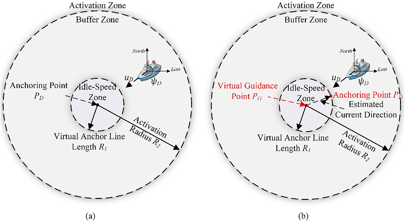
Figure 1: Schematic diagram of the anchoring method: (a) Virtual anchoring method; (b) Virtual anchoring method based on dynamic virtual guide-point.
Although the virtual anchoring method has achieved satisfactory results, it still exhibits the following limitations:
• Theoretical difficulty in achieving zero steady-state error: In essence, the virtual anchoring method performs arc-keeping rather than point-keeping. Consequently, it is fundamentally challenging to eliminate steady-state position error; theoretically, the error magnitude will stabilize around the preset virtual anchor-line length
• Poor adaptability to environmental changes: When the current direction
• Contradiction in setting the virtual anchor-line length: Selecting an appropriate
The inherent limitation of the virtual anchoring method-namely, its fixed geometric constraint-makes precise point hovering inherently difficult. To address this critical issue, we developed a new approach. As shown in Fig. 1b, our method introduces a Dynamic Virtual Guide-point. The DVP replaces the fixed anchor point
The design of the controller requires a mathematical model of the USV’s motion. USV motion is commonly described by a six-degree-of-freedom (6-DOF) rigid-body model, which utilizes two right-handed Cartesian coordinate systems, as established in numerous studies. Building on our earlier research, and under the assumption of relatively stable hydrodynamic conditions (i.e., currents and tides with negligible short-term variations in speed or direction), a three-degree-of-freedom (3-DOF) model is employed. This model captures the surge, sway, and yaw motions, with its structure detailed in Fig. 2.
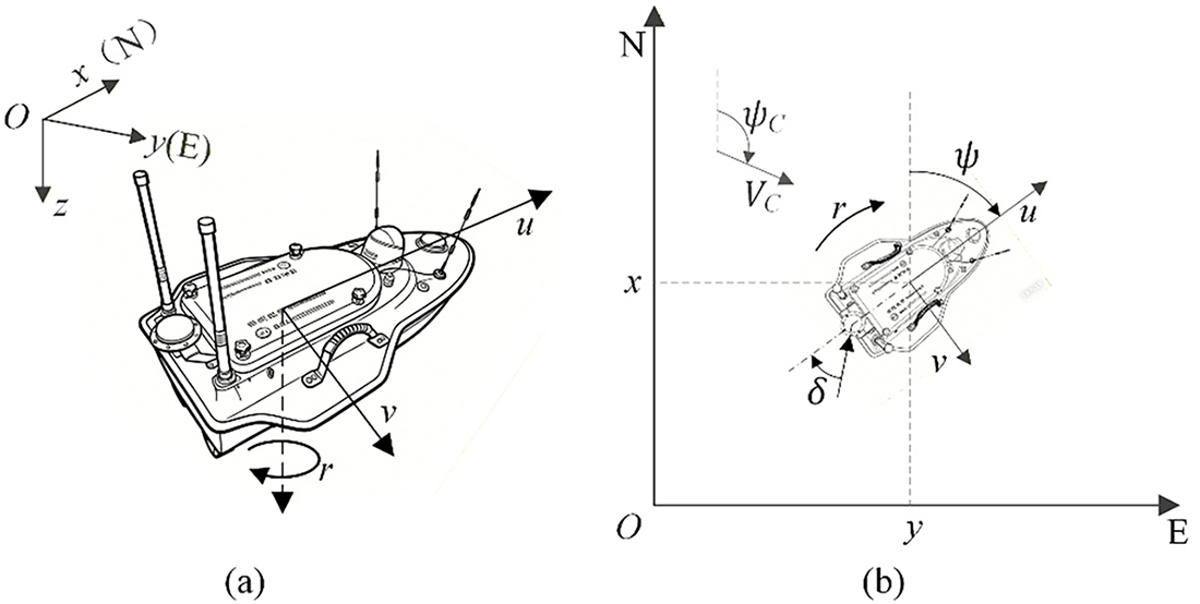
Figure 2: Coordinate system definitions for the 3-DOF ship model: (a) Earth-fixed coordinate system; (b) Body-fixed coordinate system.
Based on the principle of velocity superposition, the kinematic equations of the proposed USV model can be expressed as follows:
Here,
Furthermore, the acceleration model of the USV is described by Eq. (2):
Here,
The three limitations identified in Section 2.1, namely the arc-keeping behavior, the poor adaptability to current variations, and the trade-off involved in selecting the virtual anchor-line length
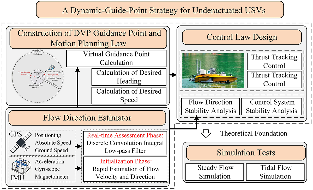
Figure 3: Architecture of the dynamic-guide-point strategy for underactuated USVs.
3.1 Dynamic Virtual Guide-Point and Motion Planning Law
As the geometric core of the control strategy presented in this work, the DVP departs from conventional methods that anchor the control target to a static point
As described in Eq. (3), the dynamic virtual guide-point
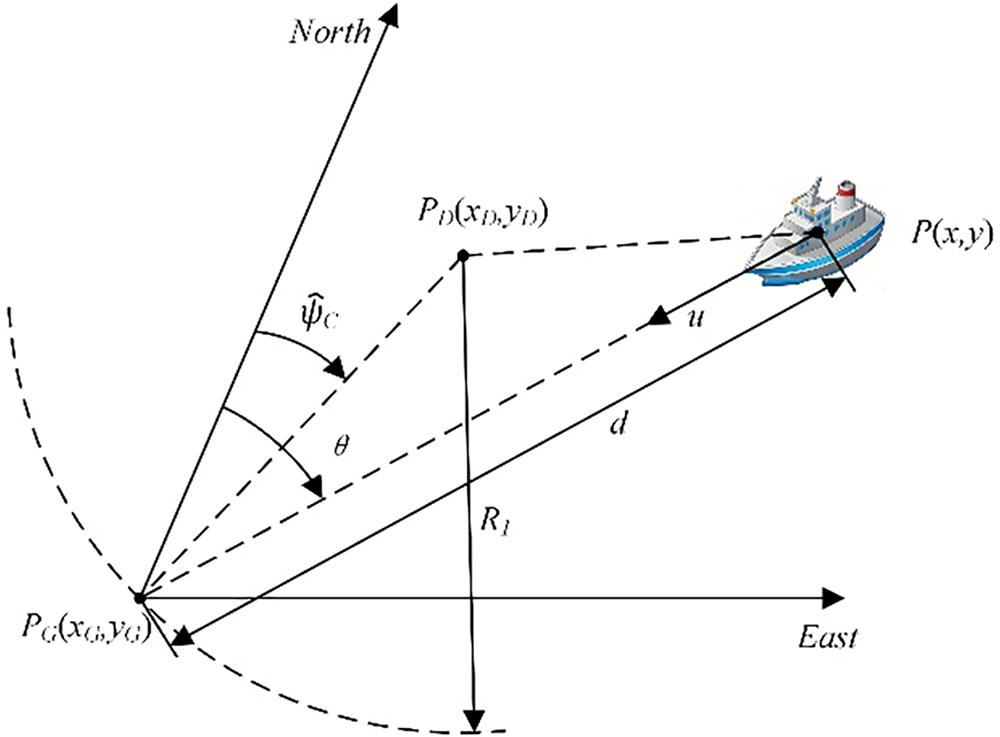
Figure 4: Schematic for high-precision station-keeping via dynamic virtual guide-point.
The generated DVP enables the design of the USV’s desired heading. The associated guidance law continuously aligns the vessel’s longitudinal axis with the time-varying guide point
Guiding the heading alone is insufficient for achieving precise positional control, necessitating the incorporation of a well-designed longitudinal speed plan. To this end, we define two concentric circular zones centered on the DVP and devise a zonal desired speed-over-ground (
The real-time distance between the USV’s position
Here
3.2 Flow-Direction Update Module
The flow-direction update module provides a real-time approximation of the current direction to enable the DVP update. It consists of two phases: an initialization phase that obtains an independent initial estimate through physical drift measurements, and an online tracking phase that uses a first-order low-pass filter to smoothly track slow variations of the current direction. This module is not intended as a formal state observer with strict observability guarantees; rather, it is a practical heuristic whose validity is empirically demonstrated and whose bounded estimation error is accommodated by the robustness of the closed-loop control system.
3.2.1 Initialization Phase: Rapid Estimation of Flow Velocity and Direction
Before the USV enters the virtual anchoring state, it undergoes a short initialization process to acquire an initial estimate of the flow state. This process simulates the “current measurement” operation performed before a ship drops anchor, requiring the power system to be shut down to let the hull drift with the current for a period. The positions at the start and end times,
This initial estimate provides the crucial initial condition
3.2.2 Real-Time Estimation Phase: Discrete Convolution-Integral Low-Pass Filtering
During this phase, the USV moves under the action of the control law, and its motion state results from the combined effect of control inputs and current disturbances. To continuously extract a smooth flow-direction signal from the coupled motion, we design a discrete convolution-integral estimator based on a first-order low-pass filter principle. The specific steps are as follows: first, an instantaneous flow-direction value is estimated; second, a discrete convolution-integral operation is performed on the instantaneous value to obtain the low-pass filtered flow-direction estimate
According to the motion planning law described in Section 3.1, when the control system drives the USV’s heading
To maintain control effectiveness under negligible or zero flow, the above flow-direction estimate is superseded by the expression below when the USV’s speed-over-ground falls below a minimum threshold:
Here,
The instantaneous observation
In Eq. (9),
Furthermore, to extract the rate of change of the true current
After obtaining the flow-direction estimate
Here,
Furthermore, the role of initialization and the boundedness of flow-direction tracking need to be further clarified in this manuscript. The initial estimates of current velocity and direction, denoted as
To achieve precise tracking of the dynamic virtual guide-point
3.3.1 Heading Tracking Controller
The objective of the heading controller is to achieve fast and accurate tracking of the desired heading
First, the heading error
Subsequently, a sliding surface
In Eq. (13),
Here,
This control law drives the sliding surface
3.3.2 Thrust Tracking Controller
The objective of thrust control is to adjust the propeller speed
Here,
In Eq. (17),
3.4 Stability Analysis Based on the Backstepping Method
In this work, however, it is necessary to verify that under the combined action of dynamic guidance, flow estimation, and tracking control, the USV can converge stably around the target point without diverging or losing control. The core error states of the overall system are defined as the flow-direction estimation error
To facilitate the derivation of the stability proof for the entire system, the backstepping method is adopted in this work, which decomposes the original complex high-order nonlinear system into multiple low-order subsystems for separate stability proofs. According to the backstepping framework, we first discuss the stability of basic motion control, i.e., the stability of distance, speed and heading angle control. On this basis, the convergence problem of flow direction angle estimation is further analyzed. Since the proof of flow direction angle estimation is relatively cumbersome in the planar Cartesian coordinate system (
3.4.1 Stability of the Closed-Loop Control System
We now analyze the stability of the main control loop. A composite Lyapunov function candidate is considered, as given by:
Differentiating
From Eq. (13), the convergence of the sliding surface
A Lyapunov function for the sliding surface is constructed as
Let
Substituting Eq. (22) into Eq. (21) yields:
Here,
Similarly, the stability of the speed loop can be derived:
Furthermore,
Here,
3.4.2 Stability of the Current Estimator
On the premise that the stability of basic motion control is achieved, it is necessary to further ensure that the flow direction angle estimation is accurate and convergent in dynamic environments, that is, whether the designed guidance law can satisfy the control objective of
In Fig. 4, for the real-time position point P, the desired positioning point PD, and the virtual guidance point PG of the unmanned surface vehicle (USV), only PG is a moving point, while the other two points are fixed points. Taking the moving point PG as the origin of the coordinate system, the motion Eq. (8) is transformed from the Cartesian coordinate system to the polar coordinate system, as shown in Eq. (27).
Under this formulation, the overall control problem of the full paper can be simplified as how to realize the dual control objectives of
By controlling the bow of the USV to always face the desired anchoring point, i.e., designing the desired heading of the USV as
Regarding the value of distance d, the control objective of
Defining the flow-direction estimation error
Assuming the flow direction changes slowly (i.e.,
Therefore, the flow-direction estimation error
4 Simulation Experiments and Results Analysis
To validate the effectiveness and superiority of the proposed DVP control strategy, a high-fidelity closed-loop control system simulation model is constructed in the Simulink (R2025b) environment. Comparative simulation experiments are then conducted. This section compares the control performance of the conventional virtual anchoring method and the proposed DVP method under two typical scenarios: constant current and 24-h tidal current. The results are analyzed in depth. The control parameters for the vessel used in all simulations are listed in Table 1.

4.1 Simulation Result under Multi-Disturbance Constant Current
Given the complex and variable nature of the marine environment, an ocean-current disturbance model was designed to achieve a more realistic simulation, as detailed in Eq. (29):
Here,
In the constant-current simulation, the initial position of the USV is set to
The 800-s trajectories of the USV under the DVP and virtual anchoring methods in a constant current are shown in Fig. 5. With the DVP method (Fig. 5a), the USV travels smoothly and directly toward the target, as the dynamic guide-point is updated around radius
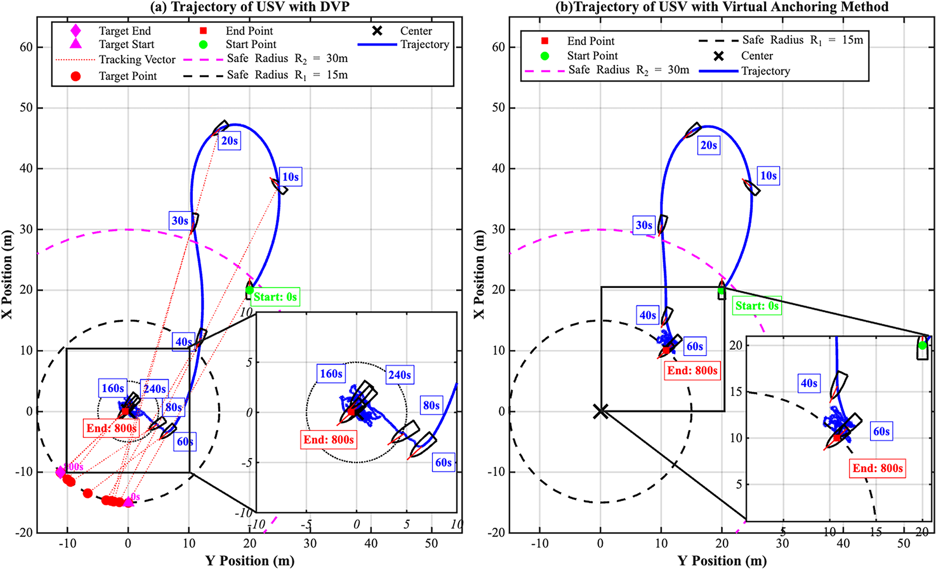
Figure 5: Trajectory comparison between the proposed DVP method and the conventional virtual anchoring method under a steady current: (a) Trajectory of USV with DVP; (b) Trajectory of USV with virtual anchoring method.
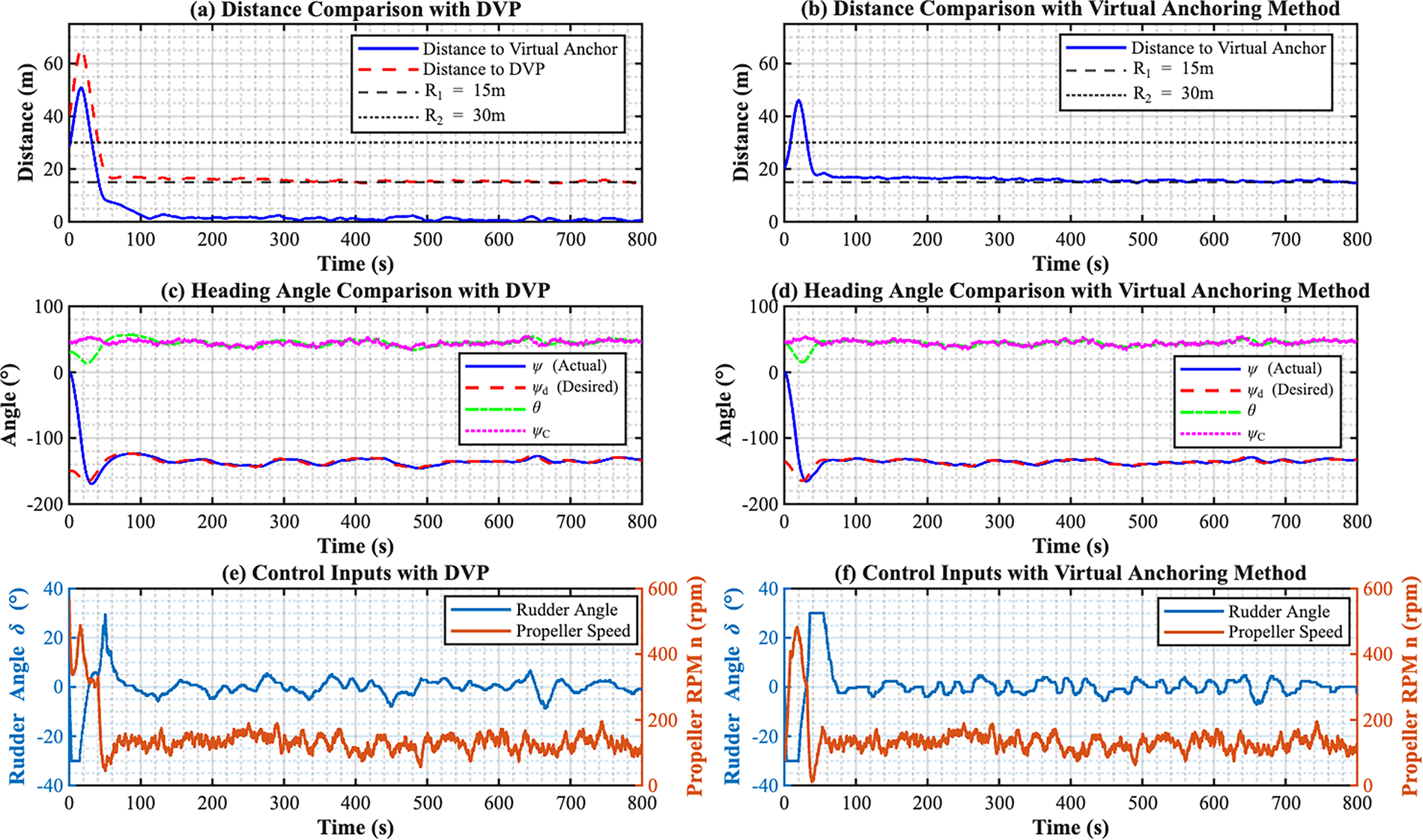
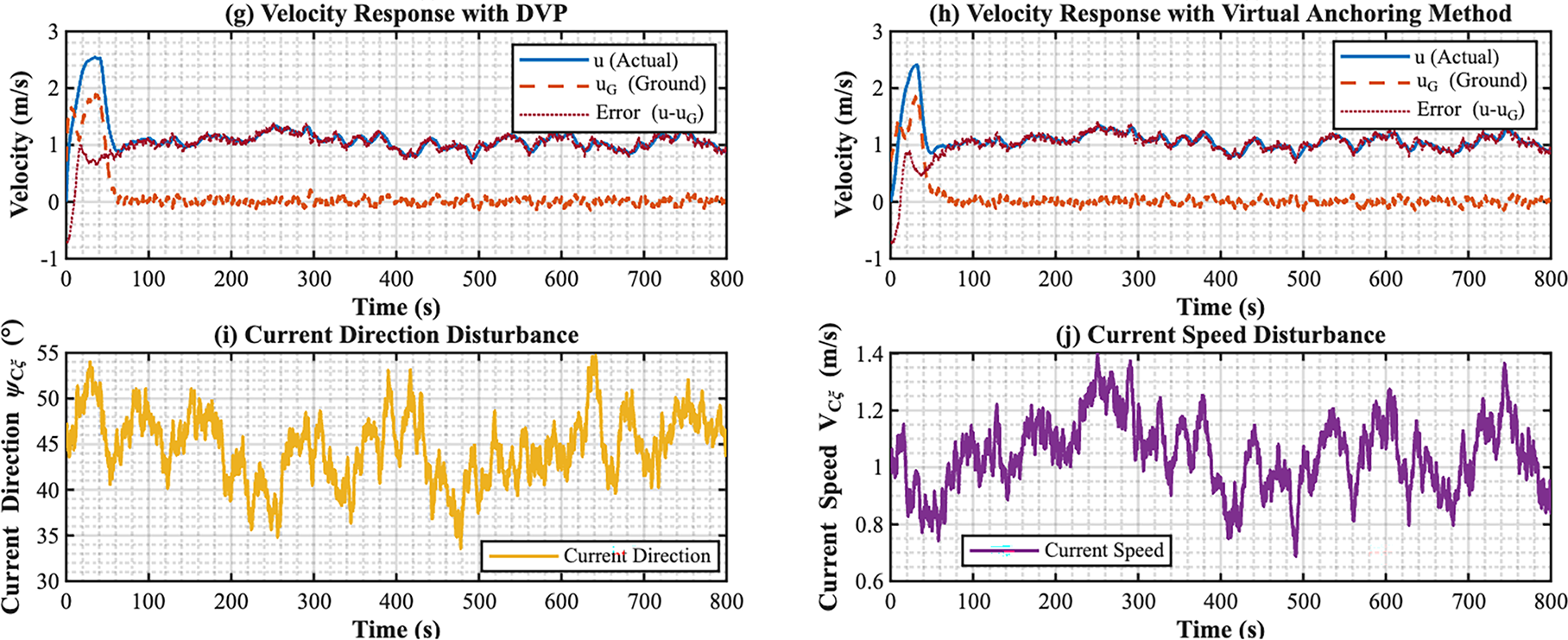
Figure 6: Comprehensive performance comparison between the proposed DVP method and the conventional virtual anchoring method: (a) Distance comparison with DVP; (b) Distance comparison with virtual anchoring method; (c) Heading angle comparison with DVP; (d) Heading angle comparison with virtual anchoring method; (e) Control input with DVP; (f) Control input with virtual anchoring method; (g) Velocity response with DVP; (h) Velocity response with virtual anchoring method; (i) Current direction disturbance; (j) Current speed disturbance.
To comprehensively evaluate the convergence, robustness, and environmental adaptability of the DVP control strategy under different marine conditions, we conducted adaptability simulations. This was done by maintaining the simulation parameters and controller settings from prior verification tests and systematically varying only the USV’s initial state and the current conditions, as specified in Table 2.
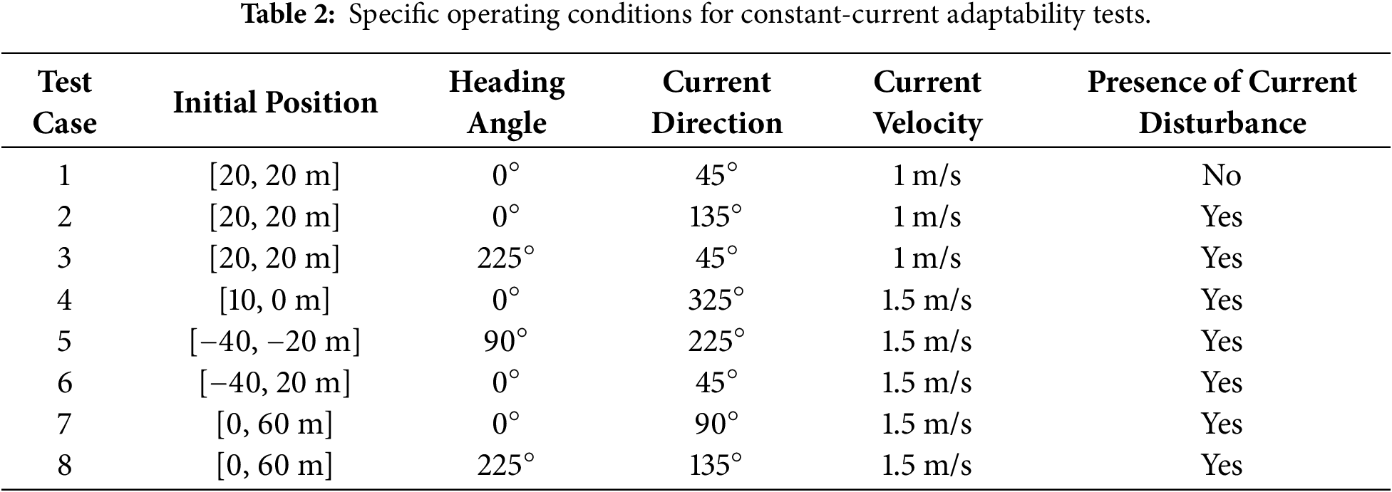
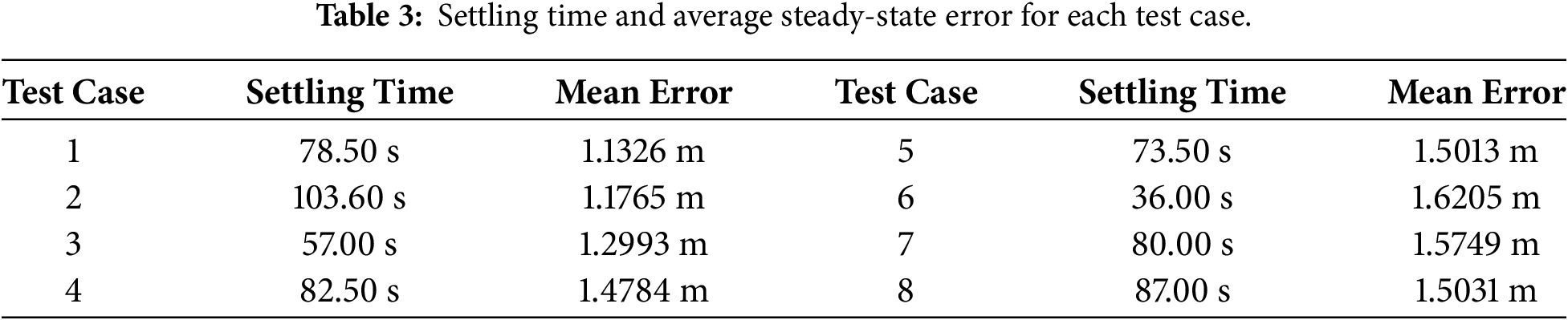
The results are shown in Fig. 7 and Table 3. Here, the settling time refers to the time required for the USV to be within 5 m of the anchor point, and the average error is the mean distance from the anchor point after the settling time. As illustrated in Fig. 7, in all test cases, the USV successfully converged to the target point from various initial positions and ultimately maintained a heading-into-current orientation. Specifically, Fig. 7a–c show that with a fixed initial ship position, the controller autonomously planned an effective approach path regardless of changes in the current direction. Notably, in Fig. 7c, the USV did not take the most direct up-current path to the target, which is likely attributable to an initial estimation error in the flow-direction observer. In Fig. 7d–f, the current speed was increased, and the USV was placed in different quadrants. The trajectories demonstrate that the control strategy still ensured stable convergence, proving its global stability from different initial locations. Finally, Fig. 7g,h verify the effectiveness of the control strategy over a certain range. Moreover, from the average errors in Table 3, it can be observed that the steady-state error increases slightly as the current speed increases. Taken together, this set of experiments confirms that the DVP strategy provides an effective solution for achieving high-precision, highly reliable point-keeping for underactuated USVs in complex, unknown current environments.
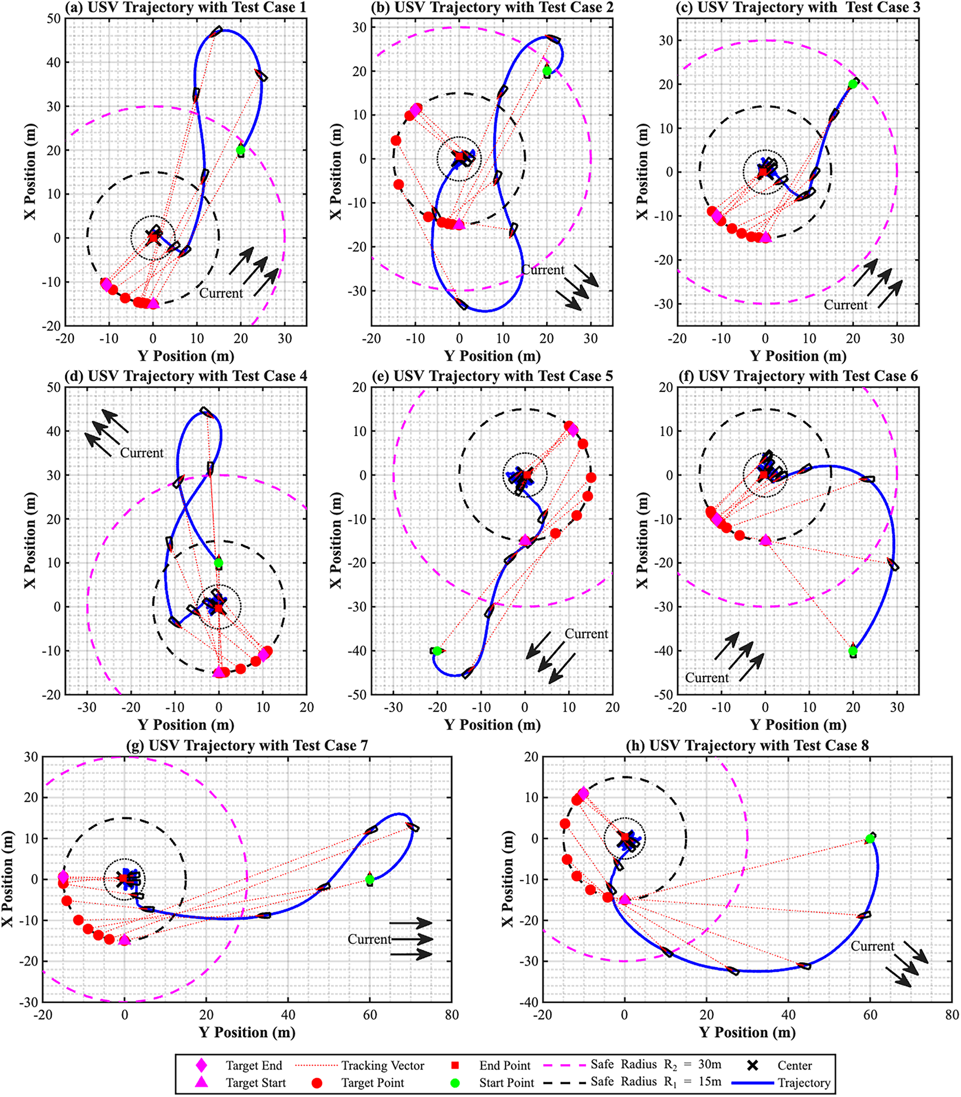
Figure 7: Trajectories of the USV in constant-current adaptability simulations: (a) Test Case 1; (b) Test Case 2; (c) Test Case 3; (d) Test Case 4; (e) Test Case 5; (f) Test Case 6; (g) Test Case 7; (h) Test Case 8.
4.2 Simulation Result under Tidal Current
Given the highly variable nature of oceanic currents, simulations were conducted to evaluate the DVP control strategy under tidal conditions. Tidal forces induce two flood-ebb cycles per day, resulting in specific flow patterns with varying directions and speeds. The tidal model developed in our prior work [36] is employed in this study, as described by the following equation:
To improve computational efficiency, the simulation duration was scaled down from 86,400 to 8640 s, with a fixed step size of 0.1 s. The initial position of the USV and the anchoring point were set to (20, 20) and (0, 0), respectively. All initial states of the USV (
Given that tidal action induces four abrupt changes in current direction over the simulation period, the total 8640 s simulation data is divided into five phases for detailed analysis, as illustrated in Fig. 8. The results show that the DVP control strategy successfully drives the USV to converge to the anchoring point each time the current direction changes drastically. Specifically, every directional shift requires the USV to reorient itself and replan its path to quickly restore a heading-into-current attitude. Relevant vessel and current data are provided in Fig. 9. Under the sustained 24-h tidal condition, the DVP strategy demonstrates excellent environmental adaptability, strong robustness, and high steady-state precision. It not only achieves global convergence from arbitrary initial points to the target but also maintains precise “point-keeping” control over extended periods under continuous external disturbances. This effectively overcomes the inherent problem of steady-state position drift in traditional methods when the current direction changes, demonstrating its application potential in complex, dynamic marine environments.
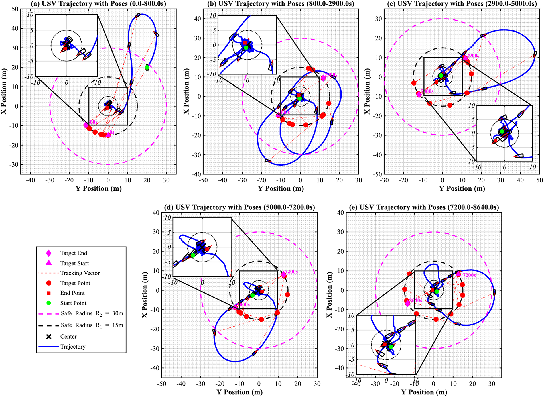
Figure 8: Segmented USV trajectories and poses under 24-h tidal current simulation: (a) USV Trajectory with pose in 0–800 s; (b) USV trajectory with pose in 800–2900 s; (c) USV trajectory with pose in 2900–5000 s; (d) USV trajectory with pose in 5000–7200 s; (e) USV trajectory with pose in 7200–8640 s.
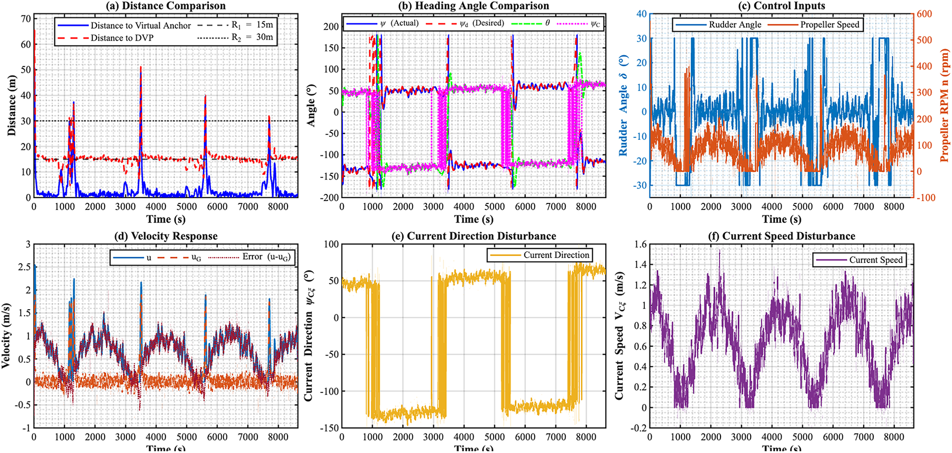
Figure 9: Time-domain responses of key parameters under tidal current disturbances: (a) Distance comparison; (b) Heading angle comparison; (c) Control input; (d) Velocity response; (e) Current direction disturbance; (f) Current speed disturbance.
In summary, under a 24-h tidal-current scenario with periodic changes in current direction, the DVP control strategy demonstrates favorable environmental adaptability, strong robustness, and high steady-state accuracy. The strategy not only achieves global convergence to the target from arbitrary initial points but also maintains precise point-keeping over prolonged periods under sustained external disturbances. It effectively addresses the drawback of steady-state position drift inherent in conventional methods when the flow direction changes, thereby confirming its significant potential for application in real-world, complex marine environments.
This manuscript proposes a DVP control strategy to address the challenge of high-precision station-keeping for underactuated USVs in unknown, time-varying currents. Specifically, we introduced a time-varying virtual guide point whose position is updated online upstream of the target point based on the estimated current direction. This effectively removes the fixed “anchor-line” constraint inherent in our team’s prior virtual anchoring method. Building on this, a complete hierarchical control system was developed, and Lyapunov-based stability analysis demonstrates the uniform ultimate boundedness of the closed-loop system. Simulation results under various scenarios, including constant and 24-h tidal currents, show that the proposed strategy successfully guides the USV to converge precisely to the target, achieving true “point-keeping.” The steady-state error is significantly lower than that of conventional methods, and the strategy demonstrates excellent environmental adaptability and robustness even during abrupt changes in current direction. The main contributions of this work are summarized as follows:
• To overcome the geometric constraint of the virtual anchoring method for underactuated vessels, a dynamically updated virtual guide point was introduced. Its position is adaptively adjusted upstream of the target based on the real-time estimated current direction, providing the theoretical foundation for achieving substantially reduced steady-state hovering error.
• An integrated robust tracking control system was designed, comprising DVP generation, a flow-direction update module based on discrete low-pass filtering, and a robust tracking controller combining sliding-mode control with adaptive integral compensation. This system effectively mitigates the steady-state position error caused by unknown currents. Stability analysis via Lyapunov methods theoretically demonstrates the uniform ultimate boundedness of the closed-loop system.
• The DVP strategy has been validated through simulations in both constant-current and 24-h tidal-current scenarios. The results indicate that the DVP strategy reduces the USV’s steady-state error to within 3 m and exhibits favorable environmental adaptability and robustness in dynamic flow conditions.
Despite the progress achieved, work on station-keeping for underactuated USVs is ongoing. Future research will focus on the following directions: (1) Implementing the algorithm on a USV hardware platform for physical model tests to evaluate the feasibility and performance of the control strategy under real-world composite disturbances and system constraints; (2) Incorporating a more comprehensive dynamic model. This study employed a simplified kinematic model; future work will consider more complete vessel dynamics. (3) Exploring deep integration with data-driven methods as a promising direction. A hybrid theory-and-data-driven approach may be investigated to further advance USV station-keeping capabilities.
Acknowledgement: None.
Funding Statement: This work was supported in part by the Natural Science Foundation of Fujian Province under Grant 2023J011570, 2023J011573, and 2023J011402; and in part by the 2023 Annual Fuzhou Marine Research Institute “Top Talents Recruitment” Science and Technology Project under Grant 2023F06.
Author Contributions: The authors confirm contribution to the paper as follows: Conceptualization, Shigan Ding and Zihe Qin; methodology, Zihe Qin; software, Zihe Qin; validation, Shigan Ding and Zihe Qin; formal analysis, Shigan Ding and Zihe Qin; investigation, Shigan Ding, Zihe Qin and Bowen Lin; resources, Zihe Qin and Feng Zhang; data curation, Shigan Ding and Zihe Qin; writing—original draft preparation, Shigan Ding; writing—review and editing, Zihe Qin, Feng Zhang, Mao Zheng and Bowen Lin; visualization, Shigan Ding; supervision, Zihe Qin, Feng Zhang and Mao Zheng; project administration, Zihe Qin; funding acquisition, Zihe Qin and Feng Zhang. All authors reviewed and approved the final version of the manuscript.
Availability of Data and Materials: The authors confirm that the data supporting the findings of this study are available within the article.
Ethics Approval: Not applicable. This study does not involve human participants or animal subjects.
Conflicts of Interest: The authors declare no conflicts of interest.
References
1. Wang Z, Qiu C, Dong Z, Cheng S, Zheng L, Chen S. Trajectory tracking of unmanned surface vessels based on robust neural networks and adaptive control. J Mar Sci Eng. 2025;13(7):1341. doi:10.3390/jmse13071341. [Google Scholar] [CrossRef]
2. Gao X, Li T. Dynamic positioning control for marine crafts: a survey and recent advances. J Mar Sci Eng. 2024;12(3):362. doi:10.3390/jmse12030362. [Google Scholar] [CrossRef]
3. Lewicka O, Specht M, Stateczny A, Specht C, Dardanelli G, Brčić D, et al. Integration data model of the bathymetric monitoring system for shallow waterbodies using UAV and USV platforms. Remote Sens. 2022;14(16):4075. doi:10.3390/rs14164075. [Google Scholar] [CrossRef]
4. Wang Y, Zhou W, Fei M, Yan H. An unmanned surface vehicle for the launch and recovery of autonomous underwater vehicles: a novel design. IEEE Robot Autom Mag. 2024;31(1):53–61. doi:10.1109/MRA.2023.3348302. [Google Scholar] [CrossRef]
5. Zheng S, Su Y, Zhuang J, Tang Y, Yi G. Fixed-time path-following-based underactuated unmanned surface vehicle dynamic positioning control. J Mar Sci Eng. 2024;12(4):551. doi:10.3390/jmse12040551. [Google Scholar] [CrossRef]
6. Du J, Hu X, Krstić M, Sun Y. Dynamic positioning of ships with unknown parameters and disturbances. Control Eng Pract. 2018;76(9):22–30. doi:10.1016/j.conengprac.2018.03.015. [Google Scholar] [CrossRef]
7. Yu Z, Wei X, Zhang H, Hu X, Han J. Composite anti-disturbance control for ship dynamic positioning systems with thruster faults. Proc Inst Mech Eng Part M J Eng Marit Environ. 2024;238(1):126–36. doi:10.1177/14750902231167073. [Google Scholar] [CrossRef]
8. Fu M, Wang L, Yu L. A finite-time output feedback control scheme for dynamic positioning system of ships. IEEE Access. 2019;7:100638–48. doi:10.1109/ACCESS.2019.2931428. [Google Scholar] [CrossRef]
9. Liu Y, Lin X, Liang K. Robust tracking control for dynamic positioning ships subject to dynamic safety constraints. Ocean Eng. 2022;266(7):112710. doi:10.1016/j.oceaneng.2022.112710. [Google Scholar] [CrossRef]
10. Hu X, Du J, Sun Y. Robust adaptive control for dynamic positioning of ships. IEEE J Ocean Eng. 2017;42(4):826–35. doi:10.1109/joe.2017.2651242. [Google Scholar] [CrossRef]
11. Tomera M, Podgórski K. Control of dynamic positioning system with disturbance observer for autonomous marine surface vessels. Sensors. 2021;21(20):6723. doi:10.3390/s21206723. [Google Scholar] [PubMed] [CrossRef]
12. Liang K, Lin X, Chen Y, Liu Y, Liu Z, Ma Z, et al. Robust adaptive neural networks control for dynamic positioning of ships with unknown saturation and time-delay. Appl Ocean Res. 2021;110(3):102609. doi:10.1016/j.apor.2021.102609. [Google Scholar] [CrossRef]
13. Mu D, Feng Y, Wang G, Fan Y, Zhao Y. Single-parameter-learning-based robust adaptive control of dynamic positioning ships considering thruster system dynamics in the input saturation state. Nonlinear Dyn. 2022;110(1):395–412. doi:10.1007/s11071-022-07657-3. [Google Scholar] [CrossRef]
14. Li H, Lin X. Robust finite-time fault-tolerant control for dynamic positioning of ships via nonsingular fast integral terminal sliding mode control. Appl Ocean Res. 2022;122(2):103126. doi:10.1016/j.apor.2022.103126. [Google Scholar] [CrossRef]
15. Chen H, Ren H, Gao Z, Yu F, Guan W, Wang D. Disturbance observer-based finite-time control scheme for dynamic positioning of ships subject to thruster faults. Intl J Robust Nonlinear. 2021;31(13):6255–71. doi:10.1002/rnc.5610. [Google Scholar] [CrossRef]
16. Sui B, Zhang J, Liu Z. Prescribed-time dynamic positioning control for USV with lumped disturbances, thruster saturation and prescribed performance constraints. Remote Sens. 2024;16(22):4142. doi:10.3390/rs16224142. [Google Scholar] [CrossRef]
17. Li J, Xiang X, Dong D, Yang S. Saturated-command-deviation based finite-time adaptive control for dynamic positioning of USV with prescribed performance. Ocean Eng. 2022;266(2):112941. doi:10.1016/j.oceaneng.2022.112941. [Google Scholar] [CrossRef]
18. Wang Z, Chen S, Dong Z, Jiang H. Composite adaptive-based trajectory tracking for unmanned surface vessels under unknown dynamics parameters. Int J Adv Rob Syst. 2025;22(5):17298806251359453. doi:10.1177/17298806251359453. [Google Scholar] [CrossRef]
19. Song W, Zuo Y, Tong S. Fuzzy optimal event-triggered control for dynamic positioning of unmanned surface vehicle. IEEE Trans Syst Man Cybern Syst. 2025;55(3):2302–11. doi:10.1109/TSMC.2024.3520600. [Google Scholar] [CrossRef]
20. Zheng M, Su Y, Chen G. An improved sampled-data control for a nonlinear dynamic positioning ship with Takagi-Sugeno fuzzy model. Math Biosci Eng. 2024;21(5):6019–41. doi:10.3934/mbe.2024265. [Google Scholar] [PubMed] [CrossRef]
21. Zou Z, Zheng M. Design and stabilization analysis of luxury cruise with dynamic positioning systems based on sampled-data control. Math Biosci Eng. 2023;20(8):14026–45. doi:10.3934/mbe.2023626. [Google Scholar] [PubMed] [CrossRef]
22. Zhang Q, Guo C. Anti-disturbance Lyapunov-based model predictive control for trajectory tracking of dynamically positioned ships. J Mar Sci Eng. 2023;11(2):281. doi:10.3390/jmse11020281. [Google Scholar] [CrossRef]
23. Deng F, Yang HL, Wang LJ, Yang WM. UKF based nonlinear offset-free model predictive control for ship dynamic positioning under stochastic disturbances. Int J Control Autom Syst. 2019;17(12):3079–90. doi:10.1007/s12555-019-0036-2. [Google Scholar] [CrossRef]
24. Hou X, Deng F, Yang H, Yu D, Zhang H, Li B. Robust nonlinear model predictive control for ship dynamic positioning using laguerre function. IEEE Access. 2022;10:127563–74. doi:10.1109/ACCESS.2022.3222762. [Google Scholar] [CrossRef]
25. Luan T, Tan Z, Sun M, Wang H, Li M, Yao H. Double-mode robust model predictive control of ship dynamic positioning system based on event-triggered mechanism. Ocean Eng. 2023;286(11):115536. doi:10.1016/j.oceaneng.2023.115536. [Google Scholar] [CrossRef]
26. do Nascimento AA, Feyzmahdavian HR, Johansson M, Garcia-Gabin W, Tervo K. Tube-based model predictive control for dynamic positioning of marine vessels. IFAC-PapersOnLine. 2019;52(21):33–8. doi:10.1016/j.ifacol.2019.12.279. [Google Scholar] [CrossRef]
27. Deng F, Yang H, Ding Q, Li B. Discrete-time integral fast terminal sliding mode predictive control for dynamic positioning ships with lumped uncertainties and input constraints. Int J Robust Nonlinear Control. 2025;35(5):1763–75. doi:10.1002/rnc.7754. [Google Scholar] [CrossRef]
28. Yuan W, Rui X. Deep reinforcement learning-based controller for dynamic positioning of an unmanned surface vehicle. Comput Electr Eng. 2023;110(2):108858. doi:10.1016/j.compeleceng.2023.108858. [Google Scholar] [CrossRef]
29. Sinisterra AJ, Barker A, Verma S, Dhanak MR. Nonlinear and machine-learning-based station-keeping control of an unmanned surface vehicle. In: Proceedings of the ASME, 2020 39th International Conference on Ocean, Offshore and Arctic Engineering; 2020 Aug 3–7; Virtual. doi:10.1115/omae2020-19276. [Google Scholar] [CrossRef]
30. Li J, Xiang X, Yang S. Robust adaptive neural network control for dynamic positioning of marine vessels with prescribed performance under model uncertainties and input saturation. Neurocomputing. 2022;484(2):1–12. doi:10.1016/j.neucom.2021.03.136. [Google Scholar] [CrossRef]
31. Zhang G, Yao M, Xu J, Zhang W. Robust neural event-triggered control for dynamic positioning ships with actuator faults. Ocean Eng. 2020;207(4):107292. doi:10.1016/j.oceaneng.2020.107292. [Google Scholar] [CrossRef]
32. Cheng P, Zhang C, Xie W, Zhang W, He S. Network-based adaptive multievent-triggered fuzzy dynamic positioning controller design for unmanned surface vehicles against denial-of-service attacks. IEEE Trans Control Netw Syst. 2023;10(2):612–24. doi:10.1109/TCNS.2022.3203892. [Google Scholar] [CrossRef]
33. Sarda EI, Qu H, Bertaska IR, von Ellenrieder KD. Station-keeping control of an unmanned surface vehicle exposed to current and wind disturbances. Ocean Eng. 2016;127(4):305–24. doi:10.1016/j.oceaneng.2016.09.037. [Google Scholar] [CrossRef]
34. Zhou J, Zhang H, Liu K, Ma L, Yang Y, Fan Z. Motion control system for USV target point convergence. Sensors. 2024;24(20):6589. doi:10.3390/s24206589. [Google Scholar] [PubMed] [CrossRef]
35. Tang L, Wang L, Wang Y, Zhang Y. An enhanced trajectory tracking control of the dynamic positioning ship based on nonlinear model predictive control and disturbance observer. Ocean Eng. 2022;265:112482. doi:10.1016/j.oceaneng.2022.112482. [Google Scholar] [CrossRef]
36. Qin Z, Zhang F, Xu W, Chen Y, Lei J. A model-free adaptive positioning control method for underactuated unmanned surface vessels in unknown ocean currents. J Mar Sci Eng. 2024;12(10):1801. doi:10.3390/jmse12101801. [Google Scholar] [CrossRef]
Cite This Article
 Copyright © 2026 The Author(s). Published by Tech Science Press.
This work is licensed under a Creative Commons Attribution 4.0 International License , which permits unrestricted use, distribution, and reproduction in any medium, provided the original work is properly cited.
 Downloads
 Citation Tools
