
 Submit a Paper
 Propose a Special lssue
 Open Access
ARTICLE

Method for Fault Diagnosis and Speed Control of PMSM
Department of Electrical and Instrumentation Engineering, Thapar Institute of Engineering & Technology, Patiala, Punjab, India
* Corresponding Author: Smarajit Ghosh. Email:
Computer Systems Science and Engineering 2023, 45(3), 2391-2404. https://doi.org/10.32604/csse.2023.028931
Received 22 February 2022; Accepted 13 May 2022; Issue published 21 December 2022
 View Full Text
 Download PDF
Abstract
In the field of fault tolerance estimation, the increasing attention in electrical motors is the fault detection and diagnosis. The tasks performed by these machines are progressively complex and the enhancements are likewise looked for in the field of fault diagnosis. It has now turned out to be essential to diagnose faults at their very inception; as unscheduled machine downtime can upset deadlines and cause heavy financial burden. In this paper, fault diagnosis and speed control of permanent magnet synchronous motor (PMSM) is proposed. Elman Neural Network (ENN) is used to diagnose the fault of permanent magnet synchronous motor. Both the fault location and fault severity are considered. In this, eccentricity fault may occur in the motor. To control the speed of the permanent magnet synchronous motor, Dolphin Swarm Optimization (DSO) algorithm is used. The proposed work is simulated by using MATLAB in terms of amplitude, speed and torque. The comparison graph of speed vs. torque obtained by the proposed method gives better result compared to the other existing techniques. The proposed work is also compared with Particle Swarm Optimization (PSO) and Elephant Herding Optimization (EHO) algorithm. The proposed usage of Elman Neural Network to detect the fault and the usage of Dolphin Swarm Optimization algorithm to control the speed of the permanent magnet synchronous motor gives better outcome.Keywords
Electric motors convert electrical energy into mechanical energy and they operate via the interaction between the magnetic field of the motor and current through the winding of the motor. Electric motors can be powered using DC sources (DC motors) and it can also be powered using the alternating sources (AC motors). Electric motors are classified based on their internal construction, type of power source and applications etc. Permanent magnet synchronous motor (PMSM) is an alternating current (AC) synchronous motor, and here the permanent magnets provide the field excitation of the motor [1,2]. These PMSMs are same as that of the brushless DC motors. For the field orientation accurately, knowing about the position of the rotor is not enough for the motion control. It also needs the information about the speed of rotor for controlling the closed loop. Because of its advantages it is used in area of elevator, ships, electric propulsion and electric vehicle. These PMSM motors also have disadvantages. These are magnetic faults, electric faults and mechanical faults [3]. The types of faults occured in the permanent magnet synchronous motor are presented in Fig. 1.
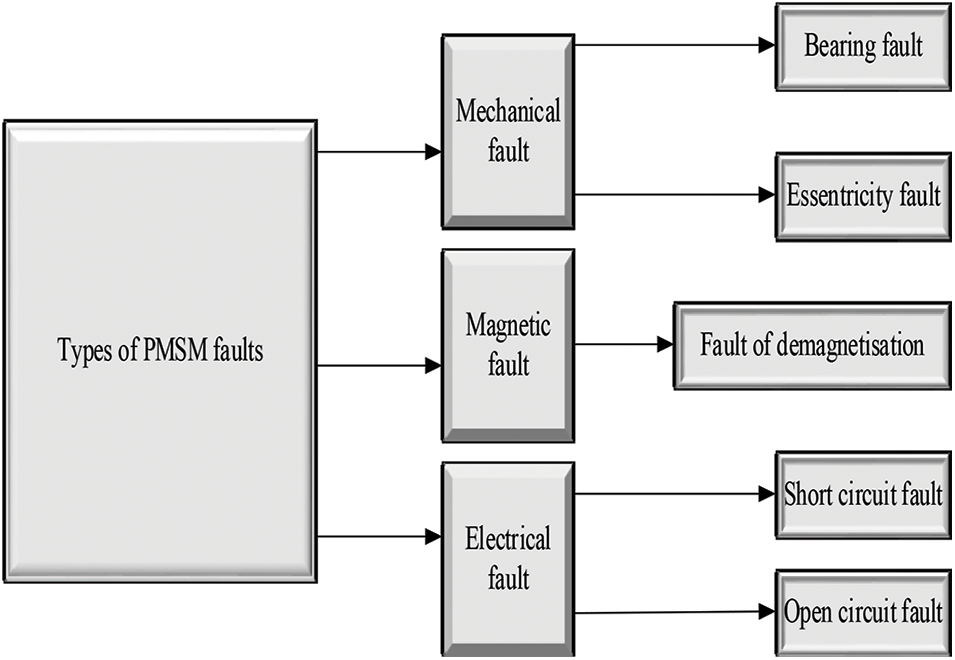
Figure 1: PMSM faults
About 40%–50% of motor failures are due to the mechanical faults and these include bearing and eccentricity fault. These faults happen because of the manufacturing defects such as the bearing tolerance, unbalanced mass and shaft bow. Magnetic fault happens because of the distribution of the magnetic flux around the air gap and the stator [4–7]. The two types of electrical faults are open and closed circuit. The fault of short circuit machine is because of the overloading of machine and high temperatures. The open circuit fault happens because of the broken winding, which bans the current circulation through the phase.
In recent years, machine learning has become a popular technique. Many studies have demonstrated that both unsupervised and supervised machine learning be effectively used in fault diagnosis. Many unsupervised learning systems have been applied in industry, such as the K-means algorithm, principal component analysis, and self-organizing map. Supervised learning systems, such as artificial neural networks, support vector machines, and partial least squares, also exhibit strong performances to engineering applications. These applications demonstrate that machine learning can be effectively solve or improve a variety of engineering problems [8–10]. In machine learning, an Elman Neural Network method has been developed for the fault diagnosis of induction motors. This method is more effective and robust than other state-of-the-art methods. Although vibration signal analysis yields good results in fault diagnosis, the removal of background noise is often a complicated process. Four layers are present in Elman Neural Network. These layers are the input layer, the hidden layer, the context layer; and the output layer [11,12]. The weights of the four layers are adjustable. Each layer connects the neighboring two layers. The issues in the motors are the fault diagnosis, which may appear while running the motor over the wide speed range. Metaheuristic optimization algorithm is used to control the speed of the motor. Here, Dolphin Swarm Optimization (DSO) algorithm is used to control the speed of the PMSM.
The rest of the research paper is organized as follow, the next section gives some analysis of related works along with the contribution of the proposed method. The third section gives the design of PMSM. The fault diagnosis of PMSM is carried out by using Elman Neutral Network to diagnose the fault of the PMSM and Dolphin Swarm Optimization algorithm is used to control the speed of the PMSM. The fourth part gives evaluation of the planned work through the MATLAB implementation. Final section provides conclusion of this research with some suggestion for future work.
In current industrial electric drive system, three phase inverters based on PMSM and power electronics are the important components. It can be said that in drive systems the most vulnerable components are the inverter power switches. The reliability of the drive system can be improved by diagnosing the inverter and by detection of fault(s). Hence these two methods were necessary in improving the reliability.
TingNa et al. [13] proposed a new method to quantize the end effect of the PMSM. They computed the end-effect co-efficient of that motor to upgrade the waveform of back-emf got from the 2D finite element model.
Qiu et al. [14] used multi-objective pigeon-inspired optimization (MPIO) to optimize the designing parameters of brushless direct current (BLDC) motors. They had also demonstrated the improvements in outcomes by using the MPIO. A Bayesian network based on driven fault diagnosis method of three phase inverter was proposed by Cai et al. [15], which was inspired by the uncertainty problem in fault diagnosis of inverters. For different fault modes two line to line voltages are measured. By using Fast Fourier Transform the signal features could be extracted. Sample dimensions were decreased by using component analysis principle. Using the experimental and simulated data, the fault diagnosis model could be trained.
Nowadays, as we know that PMSM drive based on VSIs (Voltage source inverters) are used in the industrial applications. To increase the consistency and availability of the drive, improving the reliability of voltage source inverter is the most important factor. A strong fault diagnostic technique for many IGBTs open circuit and current sensor faults in three stage drive of PMSM were discussed by Jlassi et al. [16]. For diagnosing the error, a proposed observer-based algorithm was implemented based on an adaptive threshold. Using that sensor any faults in open circuits could be differentiated easily. Those faulty sensors and power semiconductors could be separated easily. Many experimental results and simulations using controlled PMSM drive had been performed, which proved the effectiveness of the strength of diagnostic algorithm against false alarms.
A method for fault detection of short circuit separation of the PMSM had been investigated by Mazzoletti et al. [17]. The fault detection was done on the basis of RCV (residual current vector), which was formed by the difference between the stator currents measured and the current had been computed by the observer state. By employing different reference frames, false alarms occurring due to the undesired perturbations could be avoided. Hence the proposed residual current vector correctly detected the amount of fault severity. The back-electromagnetic field generated by the magnet was proportional to the rotor shaft speed. Without using any speed sensor, the electrical angular speed could be computed through the measurements of the stator voltages. The trustworthiness and the strength of the proposed method was tested for many interturn fault-conditions under transient conditions.
Fault detection methods were used for the diagnosis of three phase VSI (voltage source inverter) to increase the reliability in aggressive environment, which was discussed by Yan et al. [18]. A fuzzy based fault diagnosis method was developed based on average current Park’s vector methods. The information of phase current was utilized for computing the symptom variables using the method of average current Park’s vector. To the fault symptom variables, the fuzzy logic was applied and the information around the power switches was obtained. That proposed fault detection method not only detected the open circuit faults but also that additionally found the broken faults in the switches, which improved the unwavering quality of the motor framework. The method of proposed efficiency could be seen using both the simulation and experiments.
For online PMSM demagnetization fault diagnosis, the usage of torque ripple using CWT (continuous wavelet transforms), and GST (grey system theory) was discussed by Zhu et al. [19]. A rotor flux linkage detection model based on a torque ripple considering the electromagnetic noises was proposed at first and also employed the energy separation of the torque ripple, wavelet ridge spectrum and CWT filtering. Using that model variation in torque and the electromagnetic interferences had also been neglected. The role of the grey system theory was to simplify the demagnetization ratio and pulsations of ripple energy had been produced by demagnetization.
The contribution of the paper is organized as follow:
• Design of PMSM motor.
• Fault analysis is carried out through Elman Neural Network (ENN).
• To control PMSM motor speed, Dolphin Swarm Optimization (DSO) algorithm is utilized.
The proposed work is also being compared with other existing algorithms i.e., PSO [20] and EHO [21].
The quick production of vast amounts of product is permitted by the industrial automation. However, equipment protection still needs human involvement. In the fault diagnosis, the requirement for human intervention process has been diminished step by step due to technology improvements. Based on the vibration signal there are a few motor fault diagnosis techniques. The electrical machines of users and manufactures at first rely upon such basic protection like earth fault, overvoltage, over current and so forth to ensure safe and reliable operation. However, as the tasks performed by these machines are progressively complex and the enhancements are likewise looked for in the field of fault diagnosis. It has now turned out to be essential to diagnose faults at their very inception; as unscheduled machine downtime can upset deadlines and cause heavy financial burden. To overcome these drawbacks in PMSM, several faults diagnosis techniques are attained and among those neural networks are more efficient. As a deep network structure, this technique trains one by one layers especially. The proposed method using Elman Neural Network (ENN) and Dolphin Swarm Optimization (DSO) will provide better performance. The proposed work flow is shown in Fig. 2.
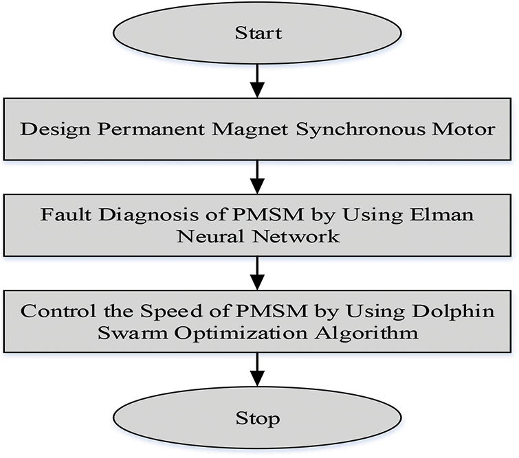
Figure 2: Proposed work flow
The following equations are used to compute the self and mutual inductance, iron losses, back EMF and copper losses.
The pole pitch can be computed by using the formula expressed by Eq. (1).
where τp represents pole pitch, Ra represents internal radius of stator and ρ indicates as number of pole pair.
Total flux can be computed by using Eq. (2).
where, ϕ represents flux, Be represents magnetic flux in air gap, Lz represents stack length and N represents the number of turns.
For computing the back EMF, the formula can be expressed by Eq. (3).
Copper losses can be computed by Eq. (4).
where, Pc represents copper losses, Rs represents stator resistance.
The equation to stator resistance is given by Eq. (5).
where, Rs represents stator resistance, p represents number of pole pair, L represents self-inductance.
The expression for total length of copper per phase is given by Eq. (6).
where, Ra represents internal radius of stator, henc represents height of the stator. Ltotal is expressed by Eq. (7).
where, Ltotal represents length of the copper wire, Lz represents stack of the length.
The inductance L can be defined as the ratio of flux linkage to the current (I) producing the flux having the unit of Henry (H), which is equivalent to a weber per ampere. The inductor is used to store energy in the magnetic field. Inductors most by and large comprise of loops of wire, regularly wrapped around a ferrite or ferromagnetic core, and their estimation of inductance is a capacity just of the physical configuration of the conductor alongside the permeability of the material through which the flux passes. Fig. 3 shows the diagram of PMSM motor.
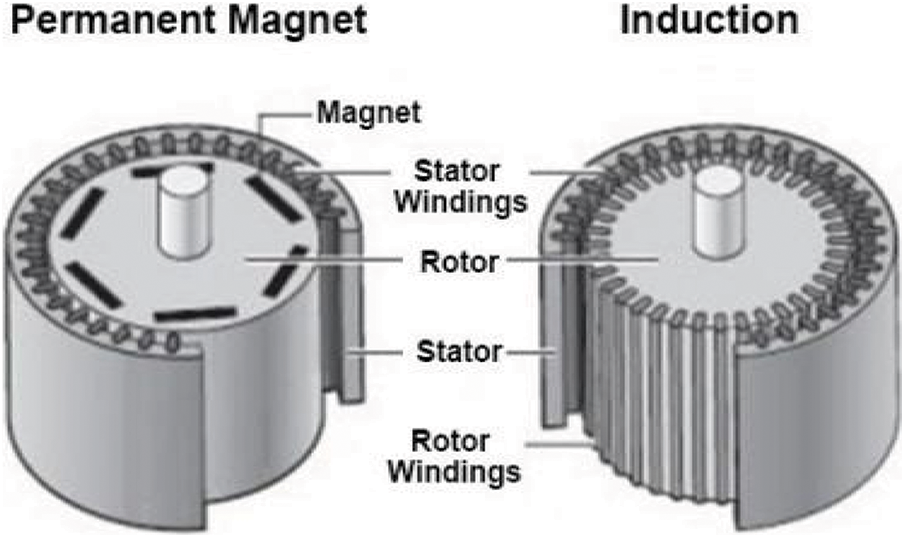
Figure 3: PMSM motor
A process for discovery the inductance is as follow:
• Let I be the current in the conductor.
• Be is determined by using Biot-Savart’s law.
• The total flux ϕ is to computed.
• To get the flux linkage, the total flux is multiplied by the number of loops.
The expression of slot pitch is given by Eq. (8).
where, τd represents slot pitch, Ra represents internal radius of the stator and Ns represents number of slots.
The self-inductance can be computed by the formula by Eq. (9).
where, L represents self-inductance, τp represents pole pitch, Lz represents stack length and e represents height of magnet and air gap.
The formula for mutual inductance is given by Eqs. (10) and (11).
where, M12 and M13 represents mutual inductances, τd represents slot pitch.
where, Leq represents equivalent inductance, L represents self-inductance.
where, Laa represents inductance at phase a and Leq represents equivalent inductance.
Torque can be computed by Eq. (14).
where, Ra is defined as the internal radius of stator, p represents the number of pole pair, q represents the number of slots/pole/phase, N represents the number of turns, Be represents the magnetic flux in air gap and Lz represents the stack length.
One of the recurrent neural networks is ENN. This network has extra inputs from the hidden layer that is context layer when compared to the traditional neural network. A set of context nodes is occupied by ENN to store the internal states. Elman back propagation algorithm is the most typical back-propagation algorithm that is used in the ENN. The structure of ENN is illustrated in Fig. 4.
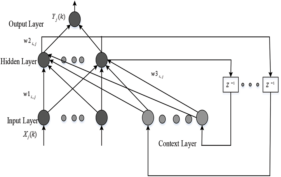
Figure 4: Elman neural network
Four layers are present in Elman Neural Network (ENN). These are input layer, hidden layer, context layer: and output layer. In ENN the distinct local networks of context nodes made its output sensitive. Based on gradient descent principle for ENN, the training algorithm is similar to BP learning algorithm. However, the context loads just as beginning context hubs yield play in the error back propagation technique that must be taken over.
where, Wij represents the weight that connects between hidden node j and input node i, Xi is the input vector, Cj represents as the weight connected between context node and hidden node, Uj represents as context layer and Bj represents as hidden layer.
Uj is the context node value, the expression is given by Eq. (16).
where, hidden layer output is called as Zj.
The sigmoid role is the designated activation function of hidden layer that is given by Eq. (17).
Where
The output of ENN is given by Eq. (19).
where, Yk represents the output of ENN and Vjk represents the weight that connects the node j in the hidden layer to the output nodes.
The state estimation of neural network is added in the ENN for updating the weight and the necessary expressions are given by Eqs. (20) and (21).
where, the estimator gains Kθ(k) should be designed [22].
3.3 Fault Diagnosis of PMSM by Using ENN
The PMSM working conditions has shown that there are indirectly replicated in its feature signal. The possibility of the ENN-based motor fault discovery plot is to initially expect the time arrangement of this feature signal with ENNs and after that review any doubtful change in the expectation attributes, which is thought to be produced by emerging fault. By using ENN, the training phase of PMSM is shown in Fig. 5.
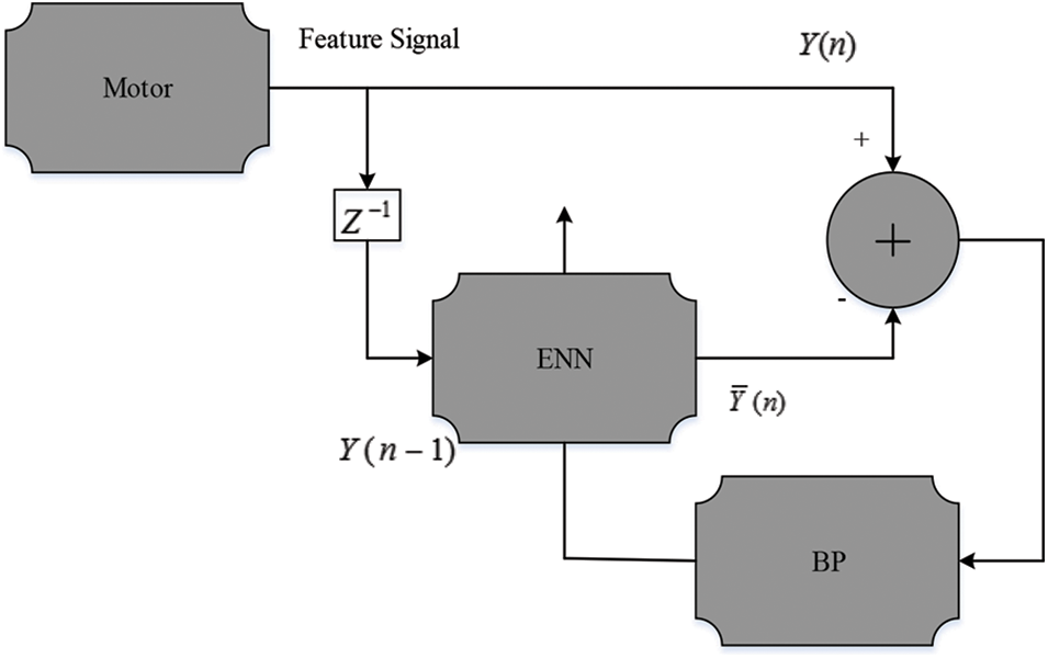
Figure 5: Training phase of ENN based PMSM
Here, the ENN the feature signal value is represented as Y(n) at sample index K and the prediction output is represented by
Ep(n) is termed as the error prediction represented by Eq. (22).
The expectation of squared prediction error [EE(n)] is defined by Eq. (23).
Depending upon the variation of EE(n), the motor fault can be detected as demonstrated in Fig. 6. All the more correctly, utilizing the plan on-line for well motors, EE(n) joins to a consistent, since the trained ENN is equipped for giving an agreeable prediction of the feature signal. However, EE(n) will fundamentally diverge from the minimal value if motor is working in unusual conditions. An occurring fault has been identified when deviation becomes over a pre-set threshold.
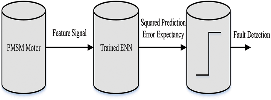
Figure 6: ENN based PMSM fault detection
So, in this case the fault in PMSM is found by using ENN. The mechanical fault of eccentricity is occurring in the PMSM. Then it is needed to rectify the fault and control the motor speed by using the Dolphin Swarm Optimization (DSO) algorithm. The below section describes the detailed explanation about DSO algorithm.
3.4 Speed Control by Using DSO
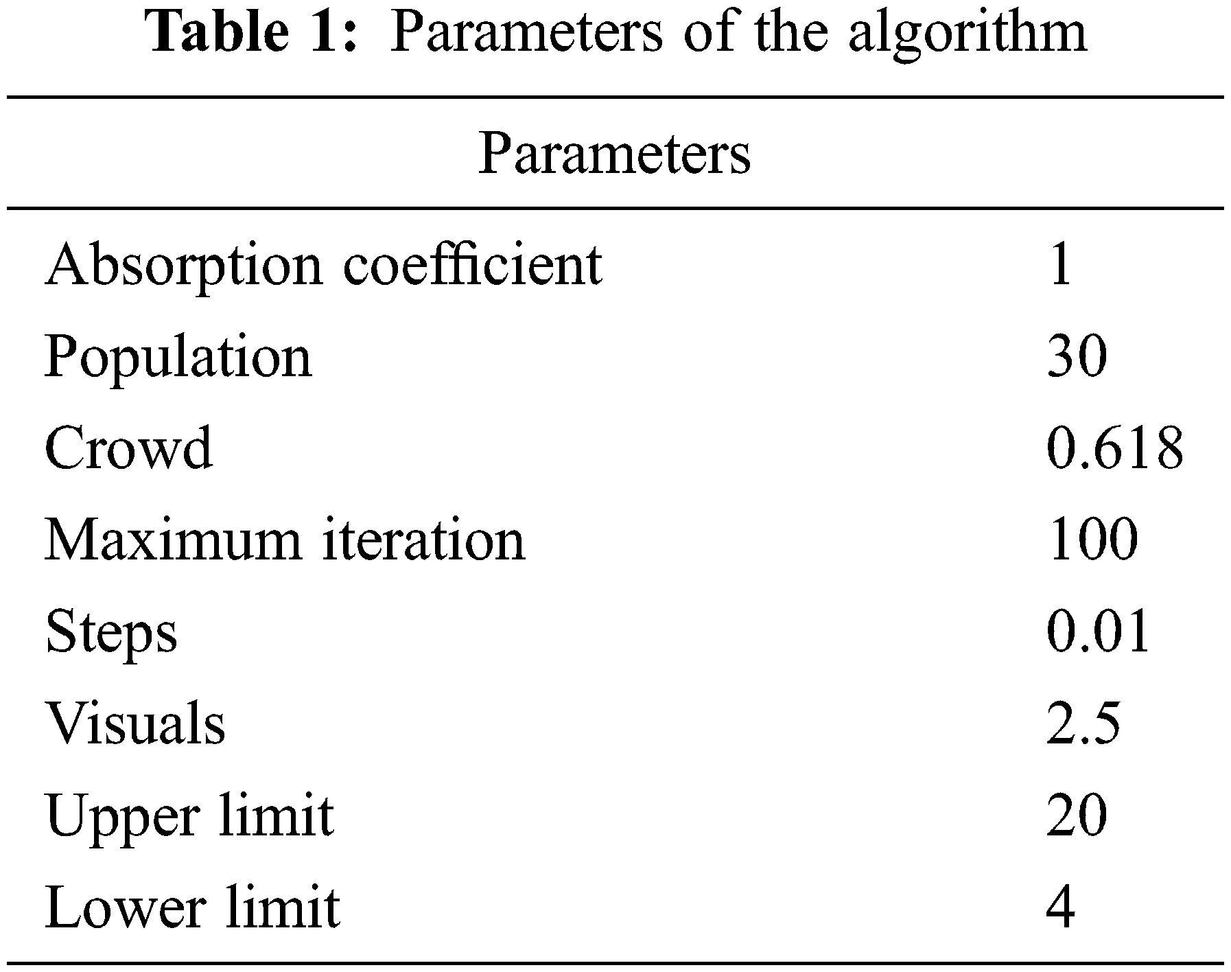
One of the smartest animals is dolphin and it has a lot of interesting biological characteristics and living habits. Three stages are considered by the dolphin predation process. Each dolphin independently takes advantage of sound to search for nearby preys in the first stage. At second, information’s are exchanged by dolphins because if the dolphin gets large prey so that it calls other dolphins for help. Once the dolphin gets the information, it moves towards the prey surrounded with other dolphins. Finally, the prey is surrounded by dolphins and then it is required to take turns and to enjoy the food. Hence the predation is accomplished. The advantages of DSO are periodic convergences, first slow then fast convergences and local-optimum-free. Additionally, it particularly appropriates to optimize the issues with more calls of fitness functions. Tab. 1 shows the parameters of the algorithm, which is related to the experiment.
First initialize the parameters of PMSM based on the DSO algorithm to control the speed of PMSM. The parameters used to control the speed of PMSM are Eb, Ia, Ra, p, f, V.
3.4.2 Varying Stator Voltage Phase
To vary the stator voltage phase is the economical method of speed control at constant frequency supply. In the inverter by controlling the switches, the three-stage stator voltage at line frequency can be measured. Decrease in stator voltage will yield a decrease in speed based on the algorithm. In the stator voltage phase, each voltage phase searches its machine by making control of the speed. In that, to prevent the machine from getting speed a maximum voltage Vmax is set. By varying stator voltage phase, the relation is expressed by Eq. (24).
where, Eb, is represented as back EMF, Ia is denoted as armature current, V is denoted as voltage and Ra is represented as armature resistance.
For the stator voltage Vs that machine gets its fitness Eij, which is computed by Eq. (25).
In the call phase, each parameter makes vary to attain the speed of the PMSM motor of its result in the stator voltage phase, including whether a better value is found. By varying frequency, armature control, change the number of poles, adding rotor resistance and change the slip to control the speed of PMSM motor.
where, P is represented as each parameter in the PMSM machine and Pi is denoted as optimal solution of each parameters in the PMSM machine.
In the control phase, each parameter needs to calculate optimal solution according to the known value and gets a new value. For each parameter the known value contains its own speed, its individual optimal solution.
where, f is the frequency.
When all the parameters values are varying, the PMSM motor updates its value. Then the algorithm meets to end the condition. If the end condition is satisfied, the PMSM motor speed is controlled.
The proposed work can be simulated by using MATLAB in terms of amplitude, speed and torque. The proposed work can also be compared with other recent techniques for the research evaluation. The existing schemes are Particle Swarm Optimization (PSO) and Elephant Herding Optimization (EHO) algorithms.
The performance of time vs. amplitude graph is shown in Fig. 7. Amplitude of the performance is increased when the time gets increased. At the time 0.5 s, the amplitude value is 0.19. At the time of 1 s, the amplitude value is 0.23 and at the time of 1.5 to 2.5 s, the amplitude value is 0.24. So finally, the amplitude gets constant value at the time of 1.5 to 2.5 s. The proposed method gives better amplitude results.
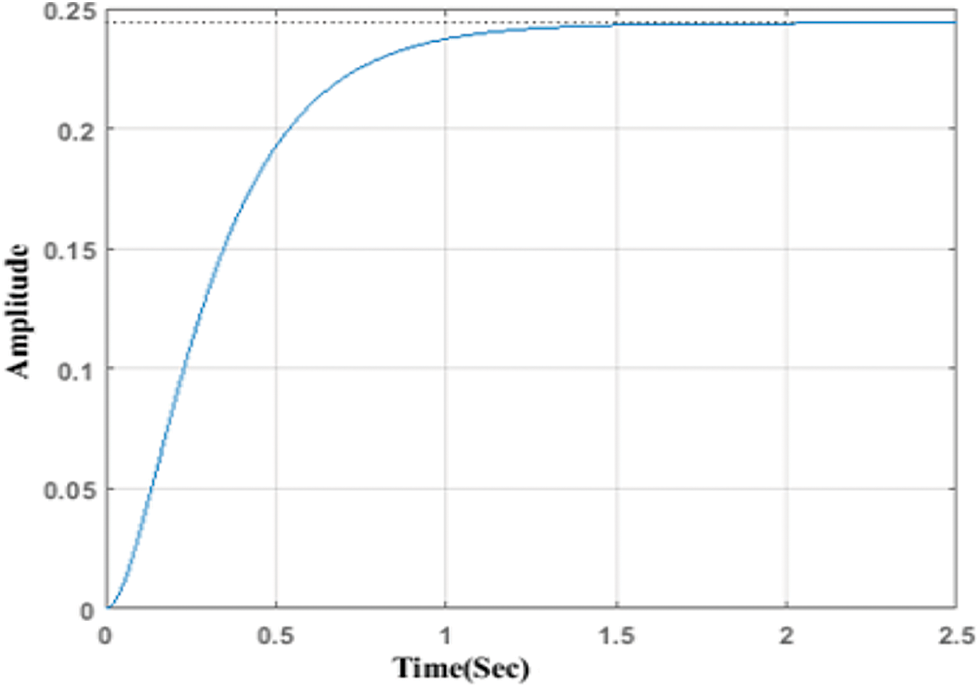
Figure 7: Time vs. amplitude
The performance of time vs. current graph is shown in the Fig. 8. When the time increases, the current of the motor is increased and decreased. At the time of 50 ms, the current value is 5.45 A. The current value is increased up to 5.45 A and decreased to 5.1 A.
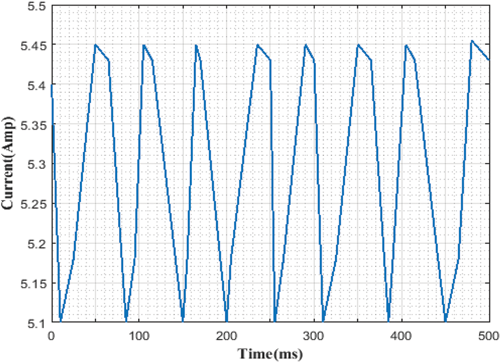
Figure 8: Time vs. current
4.3 Horse Power vs. Efficiency
The performance of horse power vs. efficiency is shown in Fig. 9. The standard motor is indicated by red color and PMSM is indicated by blue color. When the horse power is increased, the efficiency is also increased. At the horsepower 2, the efficiency of standard motor is 0.77 and PMSM motor is 0.85. So, when compared with standard motors, the proposed PMSM motor gives higher efficiency.
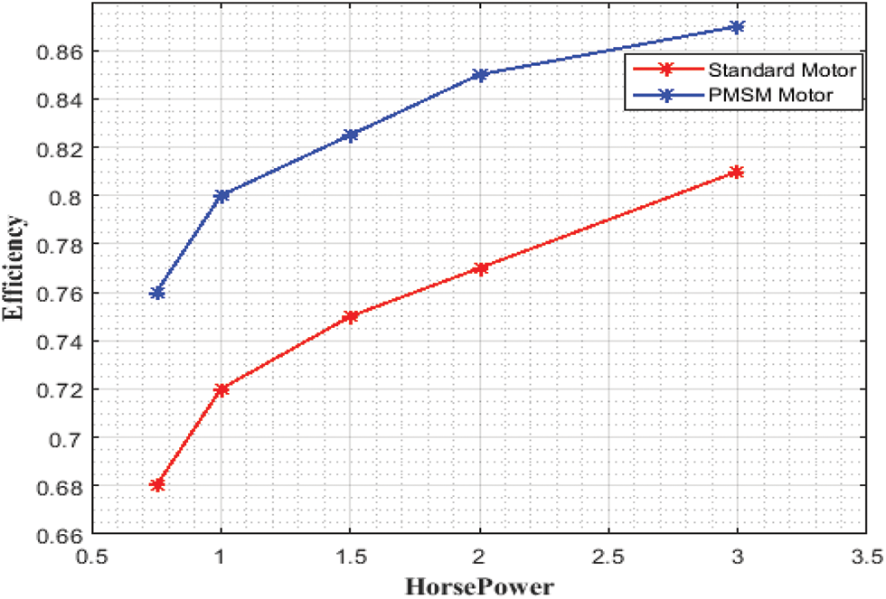
Figure 9: Horsepower vs. efficiency
The performance of speed vs. torque is graph is shown in Fig. 10. In this, the outcomes obtained by DSO algorithm is indicated by red color, Particle Swarm Optimization (PSO) algorithm is indicated by blue color and Elephant Herding Optimization (EHO) algorithm is indicated by rose color. At the speed of 800 rpm, the torque by EHO algorithm is 190 Nm, the torque by PSO algorithm is 200 Nm and the torque by the DSO is 270 Nm. The proposed algorithm gets better torque when compared with other algorithms.
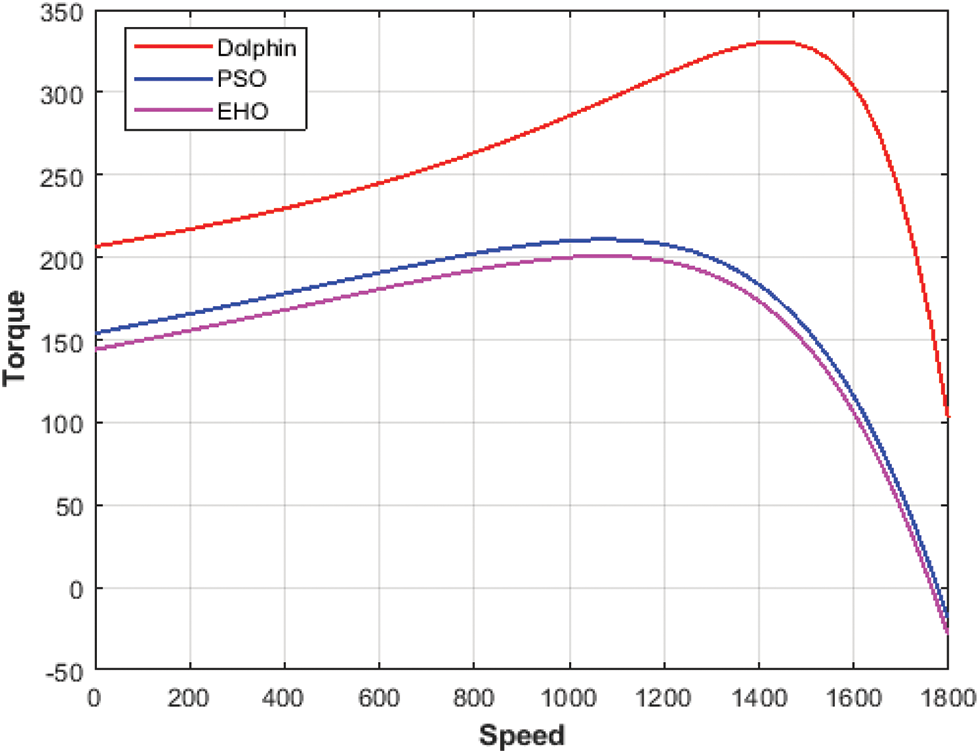
Figure 10: Speed vs. torque
4.5 Comparison of Time vs. Speed
The comparison of time vs. speed graph is shown in Fig. 11. By varying time, the speed of the machine value first slightly increases and then goes to constant speed. When DSO is compared with other existing schemes that is response curve of PI controller [23] and response curve of improved extended state observer [24], the outcome obtained by dolphin swarm optimization (DSO) algorithm gives better result.
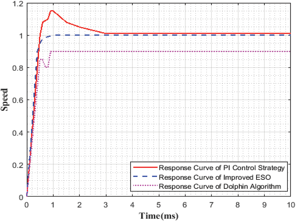
Figure 11: Time vs. speed
In this paper, fault diagnosis of permanent magnet synchronous motor (PMSM) has been carried out using Elman Neural Network (ENN). Both fault location and fault severity have been considered. To control the speed of the PMSM Dolphin Swarm Optimization (DSO) algorithm is used. The eccentricity fault may occur in the motor. The proposed work has been simulated by using MATLAB in terms of amplitude, speed and torque. The performance of speed, amplitude, torque graphs give better results. The comparison graph of speed vs. torque gives better result when compared to the other existing techniques. The existing schemes are PSO and EHO. The future improvement of the scheme is to use the advanced algorithm to find the fault of the PMSM. The proposed method gives better outcomes.
Funding Statement: The author received no specific funding for this study.
Conflicts of Interest: The author declares that he has no conflicts of interest to report regarding the present study.
References
1. Z. Qiao, T. Shi, Y. Wang, Y. Yan, C. Xia et al., “New sliding-mode observer for position sensorless control of permanent-magnet synchronous motor,” IEEE Transactions on Industrial Electronics, vol. 60, no. 2, pp. 710–719, 2013. [Google Scholar]
2. N. Bianchi and S. Bolognani, “Design optimisation of electric motors by genetic algorithms,” IEE Proceedings Electrical Power Apparatus, vol. 145, no. 5, pp. 475–483, 1998. [Google Scholar]
3. J. He, A. Fatemi, N. A. Demerdash and D. M. Ionel, “Diagnosis of stator short-circuit faults in series and parallel winding connections of closed-loop controlled PMSMs,” in IEEE Int. Electric Machines & Drives Conf. (IEMDC), Coeur d’Alene, ID, USA, pp. 1387–1393, 2015. [Google Scholar]
4. X. Sun, L. Chen, H. Jiang, Z. Yang, J. Chen et al., “High-performance control for a bearingless permanent-magnet synchronous motor using neural network inverse scheme plus internal model controllers,” IEEE Transactions on Industrial Electronics, vol. 63, no. 6, pp. 3479–3488, 2016. [Google Scholar]
5. J. Yu, P. Shi, W. Dong, B. Chen and C. Lin, “Neural network-based adaptive dynamic surface control for permanent magnet synchronous motors,” IEEE Transactions on Neural Network and Learning Systems, vol. 26, no. 3, pp. 640–645, 2015. [Google Scholar]
6. X. Zhang and Z. Li, “Sliding-mode observer-based mechanical parameter estimation for permanent magnet synchronous motor,” IEEE Transactions on Power Electronics, vol. 31, no. 8, pp. 5732–5745, 2016. [Google Scholar]
7. Y. Cho, K. Lee, J. Song and Y. Lee, “Torque-ripple minimization and fast dynamic scheme for torque predictive control of permanent-magnet synchronous motors,” IEEE Transactions on Power Electronics, vol. 30, no. 4, pp. 2182–2190, 2015. [Google Scholar]
8. S. Hamid, S. N. Ismail, M. Hamzah and A. S. Malik, “Developing engagement in learning management system supported by learning analytics,” Computer Systems Science and Engineering, vol. 42, no. 1, pp. 335–350, 2022. [Google Scholar]
9. U. Geetha and S. Shankar, “Multi-objective modified particle swarm optimization for test suite reduction (MOMPSO),” Computer Systems Science and Engineering, vol. 42, no. 3, pp. 899–917, 2022. [Google Scholar]
10. B. Yu and T. Feng, “Simulation and optimization in engineering,” Simulation, vol. 95, no. 9, pp. 769–769, 2019. [Google Scholar]
11. R. S. Toqeer and N. S. Bayindir, “Speed estimation of an induction motor using Elman neural network,” Neurocomputing, vol. 55, no. 4, pp. 727–730, 2003. [Google Scholar]
12. Y. C. Cheng, W. M. Qiand and W. Y. Cai, “Dynamic properties of Elman and modified Elman neural network,” in Proc. Int. Conf. on Machine Learning and Cybernetics, Beijing, China, pp. 637–640, 2002. [Google Scholar]
13. S. TingNa, S. Peng, L. I. HongFeng and X. I. A. ChangLiong, “End-effect of the permanent-magnet spherical motor and its influence on back-EMF characteristics,” Science China Technological Sciences, vol. 55, no. 1, pp. 206–212, 2012. [Google Scholar]
14. H. Qiu and H. Duan, “Multi-objective pigeon-inspired optimization for brushless direct current motor parameter design,” Science China Technological Sciences, vol. 58, no. 11, pp. 1915–1923, 2015. [Google Scholar]
15. B. Cai, Y. Zhao, H. Liu and M. Xie, “A data-driven fault diagnosis methodology in three-phase inverters for PMSM drive systems,” IEEE Transactions on Power Electronics, vol. 32, no. 7, pp. 5590–6000, 2017. [Google Scholar]
16. I. Jlassi, J. O. Estima, S. K. El Khil, N. M. Bellaaj and A. J. M. Cardoso, “A robust observer-based method for IGBTs and current sensors fault diagnosis in voltage-source inverters of PMSM drives,” IEEE Transactions on Industrial Applications, vol. 53, no. 3, pp. 2894–2905, 2017. [Google Scholar]
17. M. A. Mazzoletti, G. R. Bossio, C. H. De Angelo and D. R. Espinoza-Trejo, “A Model-based strategy for interturn short-circuit fault diagnosis in PMSM,” IEEE Transactions on Industrial Electronics, vol. 64, no. 9, pp. 7218–7228, 2017. [Google Scholar]
18. H. Yan, Y. Xu, F. Cai, H. Zhang, W. Zhao et al., “PWM-VSI fault diagnosis for a PMSM drive based on the fuzzy logic approach,” IEEE Transactions on Power Electronics, vol. 34, no. 1, pp. 759–768, 2019. [Google Scholar]
19. M. Zhu, W. Hu and N. C. Kar, “Torque-ripple-based interior permanent-magnet synchronous machine rotor demagnetization fault detection and current regulation,” IEEE Transactions on Industrial Applications, vol. 53, no. 3, pp. 2795–2804, 2017. [Google Scholar]
20. R. Bala and S. Ghosh, “Optimal position and rating of DG in distribution networks by ABC-CS from load flow solutions illustrated by Fuzzy-PSO,” Neural Computing and Applications, vol. 31, no. 2, pp. 489–507, 2019. [Google Scholar]
21. S. Correia, M. Beko, L. A. D. S. Kruz and S. Tomic, “Elephant herding optimization for energy-based localization,” Sensors, vol. 19, no. 11, pp. 2515, 2018. [Google Scholar]
22. H. X. Rao, R. Lu, Y. Xu and C. Liu, “State estimation for neural networks with jumping interval weight matrices and transmission delays,” Neurocomputing, vol. 275, pp. 909–915, 2018. [Google Scholar]
23. M. Dursun, “The analysis of different techniques for speed control of permanent magnet synchronous motor,” Tehnicki Vjesnik, vol. 22, no. 4, pp. 947–952, 2015. [Google Scholar]
24. B. Liu, “Speed control for permanent magnet synchronous motor based on an improved extended state observer,” Advances in Mechanical Engineering, vol. 10, no. 1, pp. 168781401774766, 2018. [Google Scholar]
Cite This Article
 Copyright © 2023 The Author(s). Published by Tech Science Press.
This work is licensed under a Creative Commons Attribution 4.0 International License , which permits unrestricted use, distribution, and reproduction in any medium, provided the original work is properly cited.
 Downloads
 Citation Tools