
 Submit a Paper
 Propose a Special lssue
 Open Access
ARTICLE

Exploring High-Performance Architecture for Data Center Networks
1 School of Computer Science and Technology, Hainan University, Haikou, Hainan, 570228, China
2 School of Cyberspace Security (School of Cryptology), Hainan University, Haikou, Hainan, 570228, China
3 University of British Columbia, Vancouver, V6T1Z1, Canada
* Corresponding Author: Jiangyuan Yao. Email:
Computer Systems Science and Engineering 2023, 46(1), 433-443. https://doi.org/10.32604/csse.2023.034368
Received 15 July 2022; Accepted 21 October 2022; Issue published 20 January 2023
 View Full Text
 Download PDF
Abstract
As a critical infrastructure of cloud computing, data center networks (DCNs) directly determine the service performance of data centers, which provide computing services for various applications such as big data processing and artificial intelligence. However, current architectures of data center networks suffer from a long routing path and a low fault tolerance between source and destination servers, which is hard to satisfy the requirements of high-performance data center networks. Based on dual-port servers and Clos network structure, this paper proposed a novel architecture to construct high-performance data center networks. Logically, the proposed architecture is constructed by inserting a dual-port server into each pair of adjacent switches in the fabric of switches, where switches are connected in the form of a ring Clos structure. We describe the structural properties of in terms of network scale, bisection bandwidth, and network diameter. architecture inherits characteristics of its embedded Clos network, which can accommodate a large number of servers with a small average path length. The proposed architecture embraces a high fault tolerance, which adapts to the construction of various data center networks. For example, the average path length between servers is 3.44, and the standardized bisection bandwidth is 0.8 in (32, 5). The result of numerical experiments shows that enjoys a small average path length and a high network fault tolerance, which is essential in the construction of high-performance data center networks.Keywords
Data center networks (DCNs) accommodate a large number of servers and switches with high-speed links, which is an infrastructure of data centers to provide information services [1–3]. The structure of data center networks defines the connection relationship between switches and servers physically, which directly determines the level of service for users.
According to forwarding mechanisms, current data center networks can be classified into two categories: switch-centric and server-centric [4,5]. In switch-centric data center networks, the forwarding of data is completely borne by switches, where servers undertake data calculation and storage. The representative works include Fat-Tree [4], VL2 [6], Jellyfish [7], and S2 [8]. In server-centric data center networks, data forwarding is undertaken jointly by switch and server, or by multi-port server entirely where the switch is treated as a cross connector of the network. The representative works include DCell [5], BCube [9], FiConn [10] and CamCube [11,12]. However, the above server-centric architectures suffer from a large average path length and low fault tolerance, which is difficult to construct a high-performance data center network.
In this paper, we proposed a novel high-performance server-centric data center network
This paper makes two contributions as follows. Firstly, we propose a high-performance structure
The rest of this paper is organized as follows. Section 2 presents the related work of data center networks, and Section 3 describes the construction of
Based on the forwarding mechanism of networks, current architectures fall into switch-centric data center networks and server-centric data center networks. This section presents related work of data center networks in two categories, respectively.
2.1 Switch-Centric Data Center Networks
In switch-centric data center networks, servers undertake the function of data calculation and storage, and the task of data forwarding is entirely born by switches. A remarkable feature of this kind of networks is that each server is attached to a switch and does not participate in the interconnection between switches.
To solve the problems of scalability, network bandwidth, and single node failure, Fat-tree architecture was proposed, where the fabric of switches is a folded 5-stage Clos structure [4]. Based on Clos structure, servers in Fat-tree can achieve a bandwidth oversubscription ratio of 1:1. Therefore, Fat-tree can provide excellent network performance. In contrast, the structure and scale of this topology are limited by the number of ports in a switch and the average path length between servers is close to 6. Based on folded Clos, Monsoon adopts three-level switches between the aggregation and core level, and adopts two-level switches between the access and aggregation levels [13]. To improve the scalability of the network and enhance the flexibility of dynamic resource allocation, VL2 (Virtual Layer 2) was proposed to support large-scale networks through a flexible expansion, which ensures high bandwidth between servers [6]. ElasticTree can achieve energy saving by adjusting its network topology dynamically [14]. To address the challenges of scale solidification in precise structures, Jellyfish was proposed to create a data center network with different scales and incremental deployment [7]. S2 is a flexible network constructed on top-of-rack switches, which can support coordinate-based greedy routing and multi-path routing with high scalability [8]. The latest work of switch-centric networks includes Hyper-network [15], HyScale [16], etc.
2.2 Server-Centric Data Center Networks
In server-centric data center networks, servers undertake both data calculation and forwarding. A remarkable feature is that each server is equipped with two or more network interface ports to participate in the network interconnection.
To solve the scalable challenges of traditional data center networks, DCell was proposed, which recursively defined its topology [5]. A high-level DCell is built from multiple lower-level DCells through complete interconnection. To satisfy the requirements of a modular data center network, BCube was proposed, where its topology is a generalized hypercube, and the adjacent servers are connected by an
In this section, we propose a server-centric data center architecture
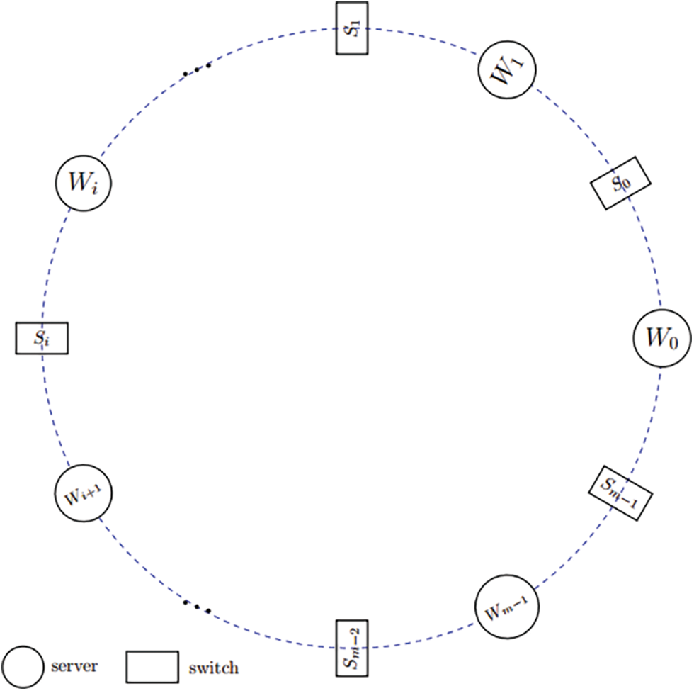
Figure 1: The vertical view of the
Fig. 2 provides a plan view of a
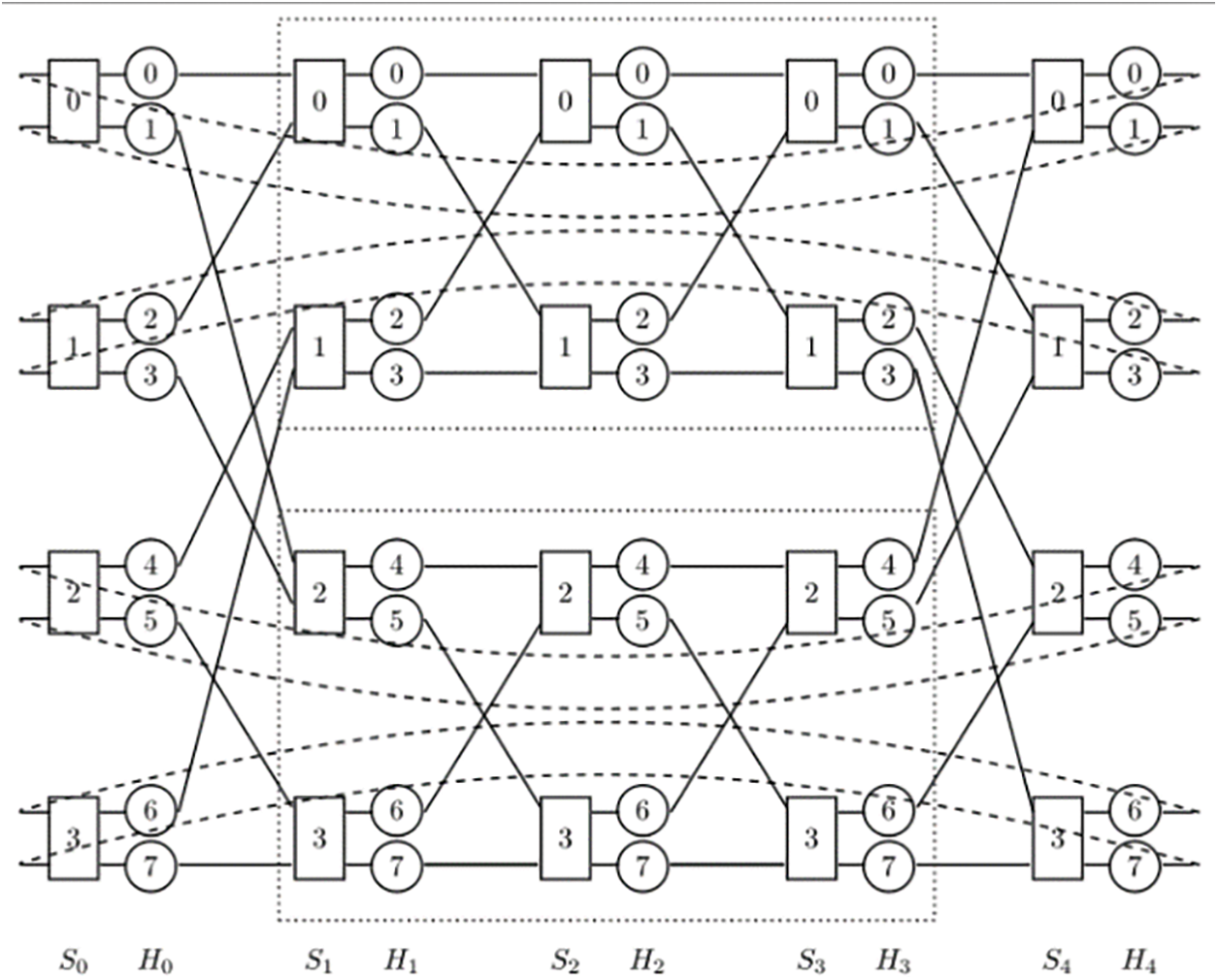
Figure 2: The plan view of a
From Fig. 2 and the above description, we learn that each
For the convenience of description, we divide ports in a switch into the left and the right side as shown in the plan view, and each part contains a half the number of ports, i.e.,
Rule 1: a server connects to the switch in its left switch column. In server column
The connection rules of the switch on the right side of a server is divided into three parts:
Rule 2: a server in column
Rule 3: server in column
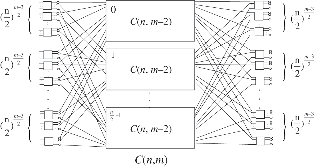
Figure 3: The modular recursive interconnection of
Rule 4: server in column
Through the above connection, the fabric of switches forms a ring Clos network structure. Logically, a
In this section, we describe the structural properties of
Network scale is a key concern of data center network performance. The number of servers reflects the computing and storage capability of a data center, which represents the scalability of the network structure.
Theorem 1: In a
Proof: According to its arrangement, the number of server columns and switch column is m in
As we learn from Theorem 1, with given m, the number of servers
Bisection bandwidth is the minimum number of links to be cut off to divide the network into two equal parts. A large bisection bandwidth indicates that the network architecture embraces excellent fault tolerance. For bisection bandwidth in
Theorem 2: The bisection bandwidth of
As we learn from the construction,
Proof: Considering the completely non-block properties of Clos structure, we learn that there is a loop between each pair of switches in column
Considering the bisection of a
With the number of servers
Network diameter is the maximum value of the shortest path length between any two servers, where a small diameter can shorten transmission delay and improve transmission efficiency. For the maximum path length between any two switches in a
Theorem 3: In a
Proof: From the plan view of
From the perspective of the server, the longest path between any two dual-port servers will pass through at most
Corollary 1: In a
The above theorem and corollary show that the network diameter of
4.4 Network Scale with Given Diameter
With a given network diameter, we consider the number of servers that a
Theorem 4: Given network diameter
Proof: According to Theorem 1 and Corollary 1, we substitute network diameter
This theorem shows that given network diameter d, the number of servers increases on power law with the number of ports n in a switch in
In this section, we conduct numerical experiments on the proposed
To verify the advantage of the short path in
Fig. 4 presents the average path length between servers and switches in
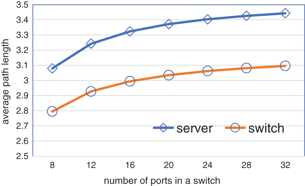
Figure 4: The average path length between servers and switches in
Fig. 5 provides the histogram of path length distribution between servers and switches in
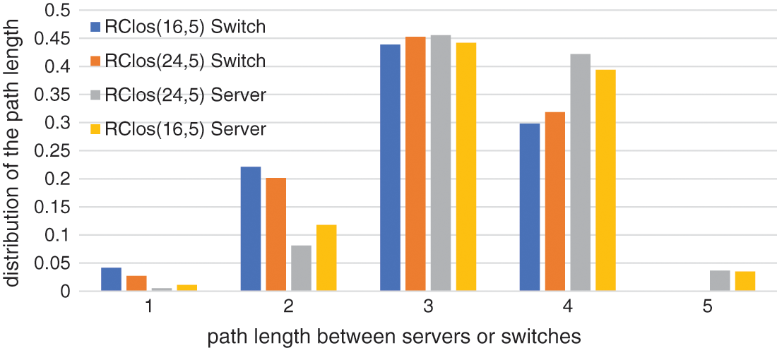
Figure 5: The path length distribution between switches and servers in
Fig. 6 presents the network diameter and path length with the ratio of server failure in
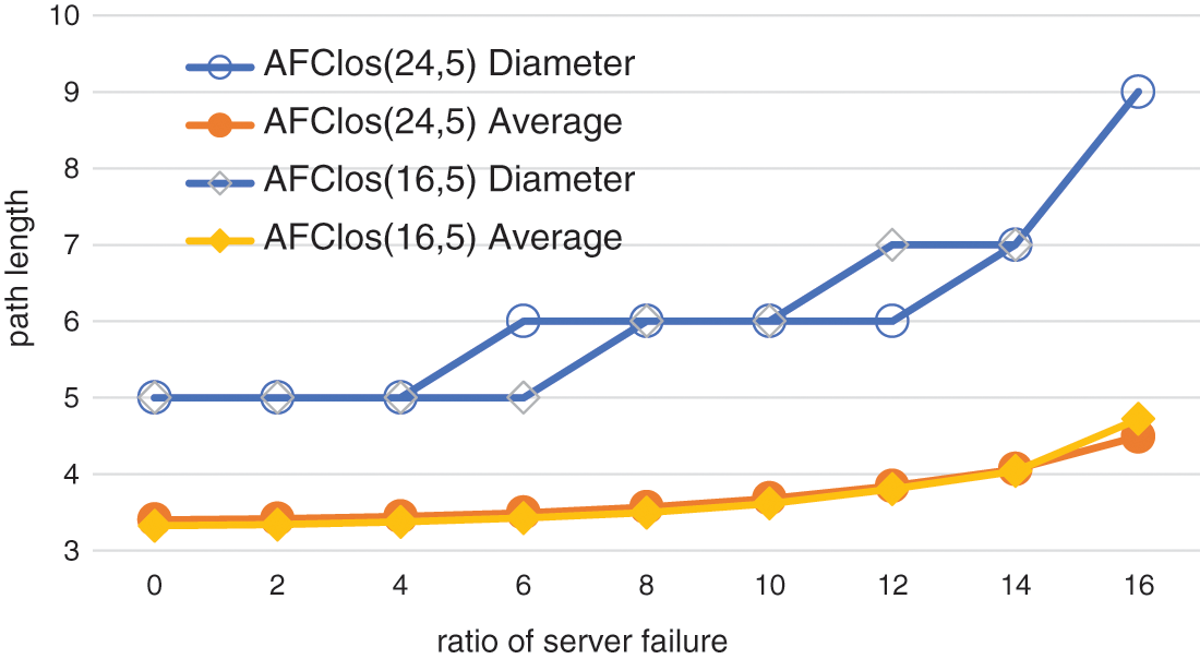
Figure 6: The network diameter and path length with the ratio of server failure in
The experimental results show that
To settle the challenges of the long routing paths and low fault tolerance, this paper proposed
Funding Statement: This work was supported by the Hainan Provincial Natural Science Foundation of China (620RC560, 2019RC096, 620RC562), the Scientific Research Setup Fund of Hainan University (KYQD(ZR)1877), the National Natural Science Foundation of China (62162021, 82160345, 61802092), the key research and development program of Hainan province (ZDYF2020199, ZDYF2021GXJS017), and the key science and technology plan project of Haikou (2011-016).
Conflicts of Interest: The authors declare that they have no conflicts of interest to report regarding the present study.
References
1. R. Jayamala and A. Valarmathi, “An enhanced decentralized virtual machine migration approach for energy-aware cloud data centers,” Intelligent Automation & Soft Computing, vol. 27, no. 2, pp. 347–358, 2021. [Google Scholar]
2. Z. Wang, H. Zhang, X. Shi, X. Yin, H. Geng et al., “Efficient scheduling of weighted coflows in data centers,” IEEE Transactions on Parallel and Distributed Systems, vol. 30, no. 9, pp. 2003–2017, 2019. [Google Scholar]
3. Y. Sanjalawe, M. Anbar, S. Al-Emari, R. Abdullah, I. Hasbullah et al., “Cloud data center selection using a modified differential evolution,” Computers, Materials & Continua, vol. 69, no. 3, pp. 3179–3204, 2021. [Google Scholar]
4. M. Al-Fares, A. Loukissas and A. Vahdat, “A scalable, commodity data center network architecture,” in Proc. of ACM SIGCOMM, Seattle, WA, USA, pp. 63–74, 2008. [Google Scholar]
5. C. Guo, H. Wu and K. Tan, “DCell: A scalable and fault-tolerant network structure for data centers,” in Proc. of ACM SIGCOMM, Seattle, WA, USA, pp. 75–86, 2008. [Google Scholar]
6. A. Greenberg, J. R. Hamilton and N. Jain, “VL2: A scalable and flexible data center network,” in Proc. of ACM SIGCOMM, Barcelona, Spain, pp. 51–62, 2009. [Google Scholar]
7. A. Singla, C. Y. Hong and L. Popa, “Jellyfish: Networking data centers randomly,” in Proc. of USENIX NSDI, Seattle, WA, USA, pp. 225–238, 2012. [Google Scholar]
8. Y. Yu and C. Qian, “Space shuffle: A scalable, flexible, and high-bandwidth data center network,” in Proc. of IEEE ICNP, Raleigh, NC, USA, pp. 13–24, 2014. [Google Scholar]
9. C. Guo, G. Lu and D. Li, “BCube: A high performance, server-centric network architecture for modular data centers,” in Proc. of ACM SIGCOMM, Beijing, China, pp. 63–74, 2019. [Google Scholar]
10. D. Li, C. Guo and H. Wu, “FiConn: Using backup port for server interconnection in data centers,” in Proc. of IEEE INFOCOM, Rio de Janeiro, Brazil, pp. 2276–2285, 2009. [Google Scholar]
11. H. Abu-Libdeh, P. Costa and A. Rowstron, “Symbiotic routing in future data centers,” in Proc. of ACM SIGCOMM, Delhi, India, pp. 51–62, 2010. [Google Scholar]
12. P. Costa, A. Donnelly and G. O’Shea, “CamCube: A key-based data center,” in Technical Report MSR TR-2010-74, Microsoft Research, 2010. [Google Scholar]
13. A. Greenberg, P. Lahiri and D. A. Maltz, “Towards a next generation data center architecture: Scalability and commoditizatio,” in Proc. of PRESTO, Seattle, Washington, USA, pp. 57–62, 2008. [Google Scholar]
14. B. Heller, S. Seetharaman and P. Mahadevan, “ElasticTree: Saving energy in data center networks,” in Proc. of USENIX NSDI, California, USA, pp. 249–264, 2010. [Google Scholar]
15. G. Qu, Z. Fang, J. Zhang and S. -Q. Zheng, “Switchcentric data center network structures based on hyper-graphs and combinatorial block designs,” IEEE Transactions on Parallel and Distributed Systems, vol. 26, no. 4, pp. 1154–1164, 2015. [Google Scholar]
16. S. Saha, J. S. Deogun and L. Xu, “Hyscale: A hybrid optical network based scalable, switch-centric architecture for data centers,” in Proc. of ICC, Ottawa, Canada, pp. 2934–2938, 2012. [Google Scholar]
17. Y. Liao, J. Yin and D. Yin, “DPillar: Dual-port server interconnection network for large scale data centers,” Computer Networks, vol. 56, no. 8, pp. 2132–2147, 2012. [Google Scholar]
18. D. Guo, T. Chen and D. Li, “Expandable and cost-effective network structures for data centers using dual-port servers,” IEEE Transactions on Computers (TC), vol. 62, no. 7, pp. 1303–1317, 2014. [Google Scholar]
19. D. Li and J. Wu, “On the design and analysis of data center network architectures for interconnecting dual-port servers,” in Proc. of IEEE INFOCOM, Toronto, Canada, pp. 1851–1859, 2014. [Google Scholar]
20. J. Y. Shin, B. Wong and E. G. Sirer, “Small-world datacenters,” in Proc. of ACM SOCC, Cascais, Portugal, pp. 1–13, 2011. [Google Scholar]
21. D. Li, H. Qi, Y. Shen and K. Li, “DPCell: Constructing novel architectures of data center networks on dual-port servers,” IEEE Network, vol. 35, no. 4, pp. 206–212, 2021. [Google Scholar]
22. Z. Zhang, Y. Deng, G. Min, J. Xie, L. T. Yang et al., “Hsdc: A highly scalable data center network architecture for greater incremental scalability,” IEEE Transactions on Parallel and Distributed Systems, vol. 30, no. 5, pp. 1105–1119, 2019. [Google Scholar]
23. Das and K. Sajal, “Book review: Introduction to parallel algorithms and architectures: Arrays, trees, hypercubes by F. T. leighton,” Acm Sigact News, vol. 23, no. 3, pp. 31–32, 1992. [Google Scholar]
24. T. W. Kim, Y. Pan and J. H. Park, “Otp-based software-defined cloud architecture for secure dynamic routing,” Computers, Materials & Continua, vol. 71, no. 1, pp. 1035–1049, 2022. [Google Scholar]
25. T. Song, Z. Jiang, Y. Wei, X. Shi, X. Ma et al., “Traffic aware energy efficient router: Architecture, prototype and algorithms,” IEEE Journal on Selected Areas in Communications, vol. 34, no. 12, pp. 3814–3827, 2016. [Google Scholar]
Cite This Article
 Copyright © 2023 The Author(s). Published by Tech Science Press.
This work is licensed under a Creative Commons Attribution 4.0 International License , which permits unrestricted use, distribution, and reproduction in any medium, provided the original work is properly cited.
 Downloads
 Citation Tools