
 Submit a Paper
 Propose a Special lssue
 Open Access
ARTICLE

Research on Virtual DC Generator-Based Control Strategy of DC Microgrid with Photovoltaic and Energy Storage
School of Automation and Electrical Engineering, Lanzhou Jiaotong University, Lanzhou, 730070, China
* Corresponding Author: Chengrui Xiao. Email:
(This article belongs to the Special Issue: Key Technologies of Renewable Energy Consumption and Optimal Operation under )
Energy Engineering 2023, 120(6), 1353-1370. https://doi.org/10.32604/ee.2023.025976
Received 08 August 2022; Accepted 07 November 2022; Issue published 03 April 2023
 View Full Text
 Download PDF
Abstract
With the penetration of a large number of photovoltaic power generation units and power electronic converters, the DC microgrid shows low inertia characteristics, which might affect the stable operation of the microgrid in extreme cases. In order to enhance the “flexible features” of the interface converter connected to the DC bus, a control strategy of DC microgrid with photovoltaic and energy storage based on the virtual DC generator (VDCG) is proposed in this paper. The interface converters of the photovoltaic power generation system and the energy storage system simulates the inertia and damping characteristics of the DC generator to improve the stability of the DC bus voltage. The impedance ratio of DC microgrid was obtained by establishing the small-signal model of photovoltaic power generation system and energy storage system, and the Nyquist curves was applied to analyze the small-signal stability of the system. Finally, the simulation results were verified with MATLAB/Simulink. The results show that the proposed control strategy can slow down the fluctuation of bus voltage under the conditions of photovoltaic power fluctuation and load mutation, thus enhancing the system stability.Keywords
In order to achieve the goal of carbon peak and carbon neutrality, the increasing penetration of renewable energy and power converters brings direct impact on the stability of the power system due to the lack of inertia and damping [1,2]. As an important part of the power system, easy to control and without having to consider frequency, reactive power and other factors, the DC microgrid receives extensive attention [3,4]. However, a large number of stationary power generation units, especially photovoltaic (PV) and power converters, are connected to the DC bus in microgrid, exhibiting characteristics of low inertia and weak damping, which may challenge the operation and control of DC microgrids, leading to the voltage instability [5].
In DC microgrids, droop control and other improved strategies based on it are usually used to maintain the power balance, thus stabilizing the DC bus voltage. However, these control methods failed to enhance the inertia of the microgrid. Inspired by the virtual synchronous generator (VSG) based control for AC microgrid, the concept of virtual DC generator (VDCG) control is proposed to improve the inertia and damping of DC microgrids [6–9]. References [10–12] have shown that VSG control is adopted in the interface converter of AC side, while the virtual DC generator (VDCG) control is used in the interface converter of the DC side to enhance the stability of the system. VDCG is applied to the converter of the load side to reduce bus voltage fluctuation caused by random disturbance of the load [13,14]. Furthermore, references [15–19] proposed a control strategy applying VDCG to the source-side converter of DC microgrid to effectively subdue the influence caused by power fluctuation. In references [15–17], the VDCG control method was implemented in the energy storage interface converter, changing the control structure to possess superior voltage dynamic performance and inertial support ability. However, the VDCG approach used in the PV interface converter [18,19] has inertia and damping characteristics due to adding the mechanical and electromagnetic equation of DC generator. The existing research results have made forcefully positive contributions to improve inertia, but the two following problems still exist:
1) At present, the VDCG control strategy applied to PV interface converter does not consider the maximum power point tracking (MPPT) control.
2) Existing references mainly focus on single PV interface converter or single energy storage interface converter in the DC microgrid, and the VDCG control strategy is not applied in both the PV Boost converter and the bidirectional DC/DC converter for energy storage at the same time, which may enhance the flexibility of the DC bus.
In order to solve these problems, this paper adopted a two-level control strategy for the PV power generation system in the DC microgrid. The MPPT control was adopted for the former Boost1 converter, and the VDCG control was used for the latter Boost2 converter. On the other hand, the VDCG control strategy was also applied to the energy storage system in the DC microgrid, which can not only maximize the output power of the PV power generation unit but also improve the inertia of the system. The bode diagram was used to analyze the influence of VDCG control on system stability. Besides, the small-signal model of the DC microgrid with PV and energy storage was established. The influence of main parameters on the stability of the system was determined using the impedance ratio criterion. Finally, the accuracy and effectiveness of the proposed method were verified by simulation and analysis.
2 Structure of DC Microgrid with PV and Energy Storage
A DC microgrid is usually composed of distributed power supplies, an energy storage system, load units and corresponding interface converters. The DC microgrid researched in this paper is composed of a PV micro-source and an energy storage, and the system structure is shown in Fig. 1. The PV power generation system adopts a two-level topology structure. By controlling the front Boost1 converter, the PV array operates in MPPT mode based on perturbation and observation method (P&O). However, in order to enhance the inertia of PV power generation system connected to DC bus, the Boost2 converter utilizes the VDCG control strategy. The bidirectional DC/DC converter controlled by VDCG is regarded as the intermediate link between the energy storage system and the DC bus to improve the flexibility characteristics, while the load is directly connected to the DC bus through the DC/DC converter. When the system is in grid-connected state, the DC microgrid can connect to the AC grid through the DC/AC interface converter to provide the grid-connected power PGrid.

Figure 1: Topology of DC microgrid with photovoltaic and energy storage
This paper mainly studied the control strategy of DC microgrid in the isolated island mode. The PV power generation system and energy storage system jointly suppress the random power fluctuation to improve the stability of the DC bus voltage when the system is disturbed by PV power fluctuations and sudden load changes.
3 Control Strategy of DC Microgrid Based on VDCG
Similar to VSG control strategy, the VDCG control strategy integrates mechanical and electromagnetic equations into the control of DC converter. Consequently, the external characteristics similar to that of a DC generator is supplied to the output port of converter. The DC converter is equivalent to a two-port network, and the VDCG equivalent model obtained is shown in Fig. 2. Uin and Iin are the input voltage and input current of the DC converter, respectively, Iout is the output current and Uo is the output voltage of the DC converter.

Figure 2: Equivalent model of VDCG
The mathematical model of VDCG is as follows:
1) Mechanical equation:
where J is the moment of inertia and D is the damping coefficient, ω and ω0 are the actual angular velocity and rated angular velocity, respectively. Tm, Te is mechanical torque and electromagnetic torque respectively and Pe is electromagnetic power.
2) Electromagnetic equation:
where Ea is the armature induced electromotive force, U is the terminal voltage, Ia is armature current, Ra is armature resistance, CT and φ are torque coefficient and flux at each pole, respectively.
According to Eqs. (1)~(4), the control structure of the DC generator link was established. By adding the DC generator link to the converter control, the VDCG control strategy can be obtained, as is shown in Figs. 3a and 3b, respectively.
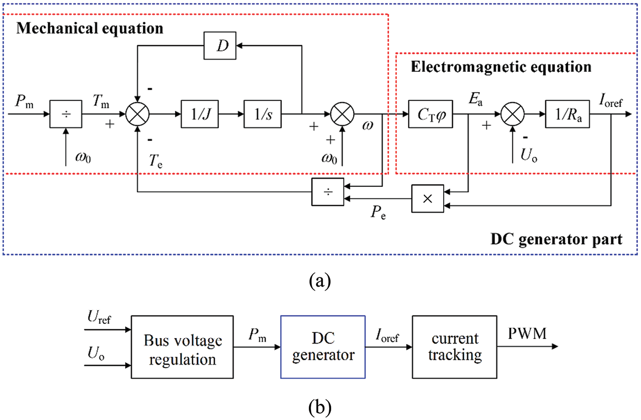
Figure 3: (a) The DC generator link, (b) The VDCG control strategy
The VDCG control strategy is mainly composed of a control link including bus voltage regulation, DC generator and current tracking. The bus voltage regulation mainly suppresses the voltage fluctuation, maintaining the mechanical power Pm as the input of the DC generator link. In the DC generator control, when Pm changes suddenly, the angular velocity ω and the armature induced electromotive force Ea will change slowly due to the role of inertia J and damping coefficient D. Therefore, the change of the output power Pe is also subdued. In the current tracking control, the output current reference value Ioref is converted to the input current reference value according to the power balance principle of the converter, which is used as the current loop reference value to achieve current tracking. Uref is the reference voltage of the DC bus.
The introduction of DC generator in the control link changes the control structure of DC converter, affecting the open-loop characteristics of the control system. As a result, the impact of key parameters on system performance is analyzed as follows and the small-signal model parameters of VDCG control strategy are shown in Table 1.

Bring Δω = ω − ω0 in Eq. (1) into Eqs. (2)~(4), then the Eq. (5) can be deduced as follows:
Add small-signal disturbance into Eq. (5), then Eq. (6) can be obtained
When the perturbation is separated, Eq. (7) can be obtained according to the Eq. (6).
After the substitution of variables, then the Eq. (7) can be rearranged as shown in the Eq. (8).
After Laplace transform, the transfer function of the DC generator can be obtained
As is seen from Eq. (9), the DC generator part can be approximately regarded as the first-order inertia link, which is equivalent to a “virtual capacitor” with variable capacitance connected parallelly at the output port of the DC converter. If the values of J and D are changed reasonably, the inertia of the system will be changed in accordance. The step response curves of GVDCG for the DC generator when changing the inertia coefficient J and damping coefficient D are shown in Figs. 4a and 4b, respectively. In Fig. 4a, as coefficient J fluctuates within a certain range, the response time of the system becomes longer, and the inertial response ability of the output voltage is enhanced. As shown in Fig. 4b, under different D values, the response of the system can become faster, improving the stability.

Figure 4: (a) Step response curve when J changes, (b) Step response curve when D changes
Rearrange Eqs. (3) and (4), the expression of the Eq. (10) can be deduced as follows:
By taking the partial derivative of Eq. (10), the relationship between the output voltage deviation of the DC converter and the angular velocity deviation is shown in Eq. (11).
The small-signal model of VDCG control strategy can be obtained by analyzing the principle in Fig. 3, as shown in Fig. 5.

Figure 5: Small-signal model of VDCG control strategy
According to Fig. 5, the relation between the output voltage deviation of the DC converter and the voltage deviation of the bus is shown in the Eq. (12).
Therefore, the Bode diagram of VDCG control strategy with the change of J and D can be obtained, as shown in Figs. 6a and 6b. It can be seen from Fig. 6a that the cutoff frequency and phase angle margin of the system basically remain unchanged when the inertia coefficient J increases, so the change of J has no obvious influence on the stability of the system. In Fig. 6b, the cutoff frequency and phase angle margin of the system decreases accordingly due to the increase of the damping coefficient D. Therefore, if the D is too large, the stability and response time of the system will be affected.

Figure 6: (a) Bode diagram of G when J changes, (b) Bode diagram of G when D changes
3.2 Control Strategy of Photovoltaic Power Generation System
The two-level control strategy of PV power generation system in this paper is shown in Fig. 7. The purpose of level 1 is to determine the maximum power output for PV. The former Boost1 converter collects the output voltage and current of the PV array. The reference value UPVref in outer voltage loop can be obtained through the MPPT algorithm, and then the UPVref is compared with the actual PV output voltage to obtain the reference value IPVref in the inner current loop. On the other hand, the purpose of level 2 is to stabilize the DC bus voltage, while the Boost2 converter adopting VDCG control strategy enhances the flexibility of DC bus.

Figure 7: Two-level control strategy of photovoltaic power generation system
Based on the above analysis, the inertial energy provided by the PV power generation system to the DC bus mainly includes two parts: one is the equivalent “virtual capacitance” of the PV back-level converter using the VDCG control strategy, the other is provided by the actual output capacitor Co.
3.3 Control Strategy of Energy Storage System
Fig. 8 shows the VDCG control strategy of the bidirectional DC/DC converter, where Ub is the terminal voltage of the battery, IIb and Iob are the inductance current and output current of the converter, respectively. Rb, Lb and Cb are parasitic resistance, inductance and output capacitance of bidirectional DC/DC converter, respectively, and IIbref is the reference value of current loop.
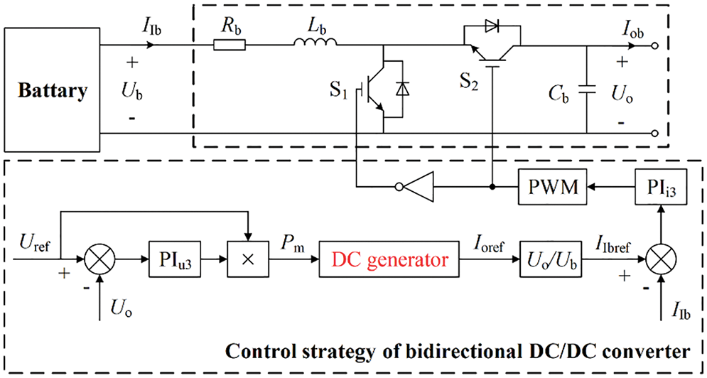
Figure 8: VDCG control strategy of energy storage system
As can be seen from Fig. 8, the inertia sources provided by the energy storage system for the DC bus mainly include three parts: the equivalent “virtual capacitance” of the bidirectional DC/DC converter using the VDCG control strategy, the inertia support provided by the actual output capacitor Cb and the equivalent inertia provided by the battery.
4 Small-Signal Stability Analysis of DC Microgrid Based on VDCG
4.1 Small-Signal Model of Back-Level Converter in Photovoltaic Power Generation System
Since the post-level converter of PV power generation system operates under the VDCG control strategy, suppose the duty cycle of the Boost2 converter is dPV2. The state space equation can be established, as is shown in Eq. (13).
Based on Eq. (13), the small-signal model of PV Boost2 converter is shown in Eq. (14).
where U1 and I1 are the output voltage and output current of PV Boost1 converter respectively, while Uo, Io and IL are the output voltage, output current and inductance current of PV Boost2 converter after adding a small disturbance near the corresponding steady-state operating point, respectively. GiLo is the transfer function from the output current to the inductance current, Gid is the transfer function from the duty cycle to the inductive current, Gud is the transfer function from the duty cycle to output voltage and Zo is the open-loop output impedance of PV Boost2 converter.
The small-signal model block diagram of the PV post-level converter using VDCG control strategy can be obtained from Eq. (14) and Fig. 7, as is shown in Fig. 9.

Figure 9: Small-signal model block diagram of the latter-level converter for PV under VDCG control strategy
It can be seen that the closed-loop output impedance Zoc of the PV back-level converter under the VDCG control strategy is deduced in Eq. (15).
where G1 is the transfer function from the bus voltage deviation to armature induced electromotive force, G2 is the transfer function from armature induced electromotive force deviation to inductance current and G3 is the current closed-loop transfer function. kPu2 and kIu2 are respectively the proportional and integral coefficient of the voltage controller under the VDCG control strategy, and kPi2 and kIi2 are respectively the proportional and integral coefficient of the current controller under the VDCG control strategy.
4.2 Small-Signal Model of Bidirectional DC/DC Converter in Energy Storage System
Since the bidirectional DC/DC converter of the energy storage system also operates in the VDCG control mode, suppose the duty cycle of the bidirectional DC/DC converter is dB. The state space equation is shown in Eq. (16).
where ub and iIb are respectively the input voltage and input current of the bidirectional DC/DC converter after adding small disturbance near the steady-state operating point, and uo and iob are respectively the output voltage and output current of the bidirectional DC/DC converter after adding small disturbance near the steady-state operating point.
According to the Eq. (16), The small-signal model of bidirectional DC/DC converter can be obtained, as is shown in Eq. (17).
where Giib is the transfer function from the output current to the input current, Gidb is the transfer function from the duty cycle to the input current, Gudb is the transfer function from the duty cycle to the output voltage and Zob is the open-loop output impedance of bidirectional DC/DC converter.
The small-signal model block diagram of bidirectional DC/DC converter under VDCG control strategy can be obtained from Eq. (17) and Fig. 8, as is shown in Fig. 10.

Figure 10: Small-signal block diagram of bidirectional DC/DC converter under VDCG control
The closed-loop output impedance Zobc of the bidirectional DC/DC converter under the VDCG control strategy can be deduced, as is shown in Eq. (18).
where G4 is the transfer function from the bus voltage deviation to armature induced electromotive force, G5 is the transfer function from armature induced electromotive force deviation to input current, and G6 is the closed-loop transfer function of current loop. kPu3 and kIu3 are respectively the proportional and integral coefficient of the voltage controller under the VDCG control strategy, kPi3 and kIi3 are respectively the proportional and integral coefficient of the current controller under the VDCG control strategy.
4.3 Small-Signal Model of DC Microgrid With Photovoltaic and Energy Storage
The corresponding energy flow diagram is shown in Fig. 11a. RLoad is the load resistance and iR is the load current. From Eqs. (15), (18) and Fig. 10, the small-signal model of DC microgrid with PV and energy storage can be established, as is shown in Fig. 11b.

Figure 11: (a) Energy flow diagram of DC microgrid, (b) Small-signal model of DC microgrid, (c) Equivalent impedance model of DC microgrid
As the front-level boost1 converter in the PV power generation system operates in MPPT mode, the PV power generation system can be seen as an equivalent to the parallel connection of current source and impedance. On the other hand, the bidirectional DC/DC converter in the energy storage system operates in the VDCG control mode, indicating that the energy storage system can be seen as an equivalent to the series connection of voltage source and impedance, as shown in Fig. 11c. Zso is the output impedance of the source side and ZLi is the input impedance of the load side.
Therefore, in the DC microgrid with PV energy source and energy storage, the ratio of the output impedance Zso of the source side to the input impedance ZLi of the load side is shown in Eq. (19).
According to the impedance ratio criterion of the cascaded system [20], if the Nyquist curve of the impedance ratio does not enter the forbidden region, the cascaded system is stable. Consequently, the Nyquist curves can be obtained when inertia coefficient J and damping coefficient D change, as shown in Figs. 12a and 12b, and the small-signal model parameters of DC microgrid are shown in Table 2.

Figure 12: (a) Nyquist curve when J changes, (b) Nyquist curve when D changes

It can be seen from Fig. 12a that the Nyquist curve moves to the right and gradually away from the forbidden zone when J increases, which improves the stability of the DC microgrid. As a result, the increase of J can attenuate the influence of disturbance on the system. In Fig. 12b, due to the increase of D, the Nyquist curve on the right part of the real axis gradually converges to the right, while the Nyquist curve on the left part of the real axis does not change significantly. Therefore, the increase of D has little influence on the stability of DC microgrid.
To sum up, the adjustment of the value of inertia coefficient J or damping coefficient D will not cause the Nyquist curve to enter the forbidden region indicating that the system is small-signal stable.
5 Simulation Analysis of DC Microgrid Based on VDCG
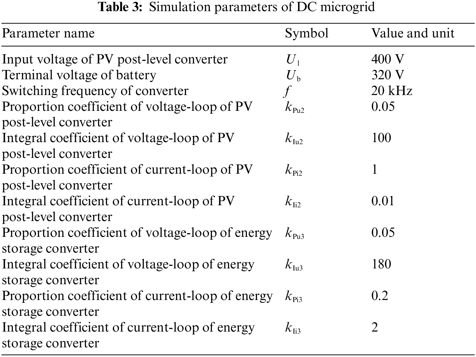
In order to verify the rationality and effectiveness of VDCG control strategy in the DC microgrid with PV and energy storage, the simulation model of the DC microgrid under the isolated island operation is built using MATLAB/Simulink simulation software. The simulation is carried out under the three conditions with different key parameters, PV power and load power. The simulation parameters are shown in Table 3.
5.1 Simulation Result of Key Parameters Change
When the structural parameters, control parameters and VDCG parameters in the microgrid change, the impact on the DC bus voltage is shown in Fig. 13.
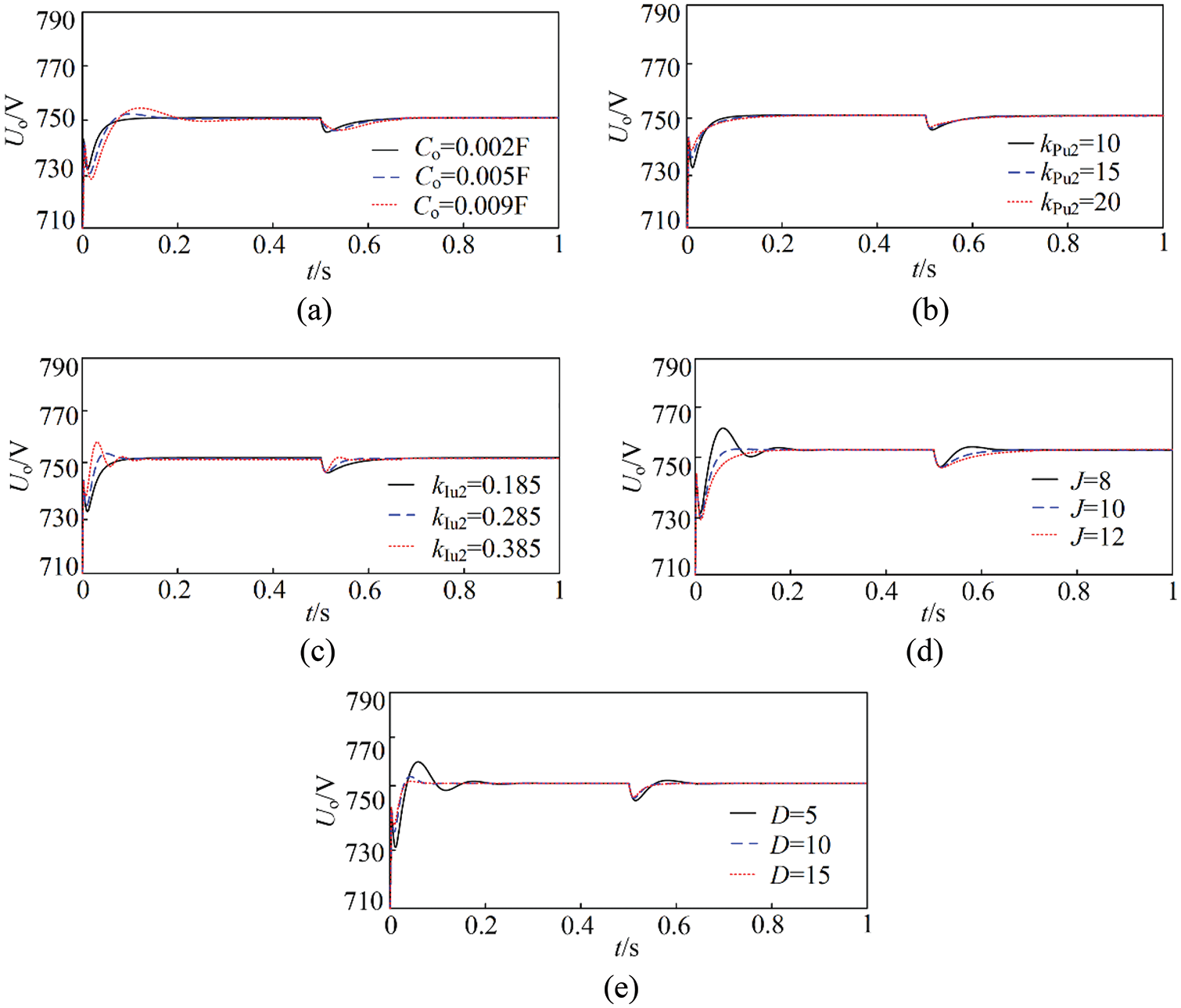
Figure 13: (a) Curve of bus voltage under the change of Co, (b) Curve of bus voltage under the change of kPu2, (c) Curve of bus voltage under the change of kIu2, (d) Curve of bus voltage under the change of J, (e) Curve of bus voltage under the change of D
It can be seen from Fig. 13a that the response of bus voltage uo is delayed, the rise time is increased and the system inertia is enhanced due to the increase of Co. In Fig. 13b, the output waveform of DC bus voltage does not change significantly when kPu2 increases, indicating that the proportional coefficient of the voltage controller has no significant effect on the system inertia. According to Fig. 13c, the increase of kIu2 causes faster response of DC bus voltage, weakened resistance to disturbance and decreased system inertia. It can be seen from Fig. 13d that the system inertia is further improved when the inertia coefficient J increases, which can effectively suppress the impact of power mutation on bus voltage. The Fig. 13e shows that the system inertia does not change significantly when the damping coefficient D increases, but the fluctuation of DC bus voltage can be slowed down and the stability of the system is improved.
5.2 Simulation Result of PV Power Change
Figs. 14a and 14b show the change curves of light intensity and output power of PV power generation system in the microgrid. When the initial light intensity of PV array is 1000 W/m2, the output power of PV power generation system is 6 kW. As the light intensity suddenly reduced to 400 W/m2 at 0.45 s, the output power of the PV power generation system became 3 kW. On the other hand, the corresponding output power of the PV power generation system was 5 kW when the light intensity is suddenly increased to 800 W/m2 at 0.75 s. It can be seen from Fig. 14c that the initial output power of the battery was 2 kW when the load consumption power remained at 8 kW during the steady-state period. Due to the sudden reduction of PV output power at 0.45 s, the output power of the battery increased to 5 kW. At 0.75 s, the output power of the battery was decreased to 3 kW because of the sudden increase of PV output power. Moreover, the change of the output power of the battery was relatively attenuated under the VDCG control strategy. In Fig. 14d, the SOC of battery was slowed down when under the VDCG control, which can effectively prevent the battery from withdrawing from power supply in advance. According to Fig. 14e, because of the change of light intensity, the output power of PV power generation system also changed accordingly. By adopting VDCG control method, the fluctuation of bus voltage can be effectively suppressed, and the system inertia can be improved. Taking the sudden change at 0.45 s as an example, the bus voltage was disturbed due to the sudden weakening of the light. The amplitude of voltage was reduced by 14.2 V and the time for voltage to recover to steady state was 0.101 s without VDCG control. Under the VDCG control, the amplitude of voltage was only reduced by 4.7 V and the time for voltage to recover to steady state was reduced to 0.028 s.

Figure 14: (a) Change curve of light intensity, (b) Output power of PV power generation system, (c) output power of battery, (d) Change curve of SOC, (e) Waveform of DC bus voltage
5.3 Simulation Result of Load Power Change
It can be seen from Figs. 15a and 15b that the load consumption power was 8 kW and output power of battery was 2 kW before 0.45 s. At 0.45 s, the load consumption power was increased to 10 kW and output power of battery was increased to 4 kW. At 0.75 s, the load consumption power was decreased to 8 kW and the output of battery was also decreased to 2 kW. Meanwhile, the output power of the battery changed smoothly under the VDCG control strategy. As can be seen from Fig. 15c, the SOC of battery slowed down significantly under the VDCG control. According to Fig. 15d, when the load consumption power suddenly increased at 0.45 s, the amplitude of bus voltage decreased by 19.5 V and the recovery time for voltage was 0.076 s. However, the amplitude of bus voltage only reduced by 8.2 V, and the time of voltage recovery to steady state was shortened to 0.054 s under the VDCG control strategy. The load power suddenly decreased at 0.75 s, the increase of DC bus voltage was 22.4 V, and the recovery time was 0.115 s. But under the VDCG control strategy, the amplitude of voltage only reduced by 8.5 V and the recovery time was 0.082 s. These results show that VDCG control strategy can weaken the voltage fluctuation and enhance the inertia of the system.

Figure 15: (a) The curve of load power, (b) The output power of battery, (c) The SOC curve of battery, (d) Waveform of DC bus voltage
In view of the low inertia and weak damping characteristics of the DC microgrid caused by the micro-source interface converters connected to the DC bus, the VDCG control is applied to the DC microgrid with PV and energy storage in this paper. The influence of key parameters on stability of DC microgrid is determined with the Nyquist curves according to the impedance ratio criterion. By analyzing the simulation results, the following conclusions can be obtained.
(1) The VDCG control strategy can significantly enhance the system stability due to the increase of inertia coefficient J and damping coefficient D.
(2) Since PV power generation system is an inertia free system, the application of VDCG control to the post-level converter of PV effectively weakens the influence of power fluctuation in the source side on the bus voltage, which in turns enhances the system inertia.
(3) As the inertia support provided by the energy storage system is limited, the fluctuation of the bus voltage caused by disturbance is suppressed by adopting VDCG control to the interface converter of energy storage.
(4) By applying the VDCG control in the PV power generation system and the energy storage system, the DC microgrid exhibits the “flexible” characteristics when connected to DC bus.
Funding Statement: This work was funded by the National Natural Science Foundation of China (52067013), and the Provincial Natural Science Foundation of Gansu (20JR5RA395).
Conflicts of Interest: The authors declare that they have no conflicts of interest to report regarding the present study.
References
1. Magdy, G., Bakeer, A., Alhasheem, M. (2021). Superconducting energy storage technology-based synthetic inertia system control to enhance frequency dynamic performance in microgrids with high renewable penetration. Protection and Control of Modern Power Systems, 6(1), 460–472. https://doi.org/10.1186/s41601-021-00212-z [Google Scholar] [CrossRef]
2. Zeng, G. H., Liao, H. F., Zhao, J. B., Zhu, X. C. (2022). A self-adaptive control strategy of virtual inertia and a damping coefficient for bidirectional DC–DC converters in a DC microgrid. Power System Protection and Control, 50(6), 65–73. https://doi.org/10.19783/j.cnki.pspc.210815 [Google Scholar] [CrossRef]
3. Satyanarayana, T., Dahiya, R. (2021). Autonomous battery storage energy system control of PV-wind based DC micro-grid. International Journal of Ambient Energy, 42(8), 1–7. https://doi.org/10.1080/01430750.2019.1567589 [Google Scholar] [CrossRef]
4. Li, H. E., Hu, J., Tang, Z. Y., Shao, X. Y., Shen, J. C. (2020). Nonlinear control technology for DC–DC converter in islanded DC microgrid. Journal of Power Supply, 18(2), 4–14. https://doi.org/10.13234/j.iSSN.2095-2805.2020.2.4 [Google Scholar] [CrossRef]
5. Xie, X. R., He, J. B., Mao, H. Y., Li, H. Z. (2021). New issues and classification of power system stability with high shares of renewables and power electronics. Proceedings of the CSEE, 41(2), 461–475. https://doi.org/10.13334/j.0258-8013.pcsee.201405 [Google Scholar] [CrossRef]
6. Mahdi, C., Seyed, H. H., Behrooz, V. (2020). New transient stability and LVRT improvement of multi-VSG grids using the frequency of the center of inertia. IEEE Transactions on Power Systems, 35(1), 527–538. https://doi.org/10.1109/TPWRS.2019.2928319 [Google Scholar] [CrossRef]
7. Yu, J. R., Sun, W., Yu, J. Q., Wang, Y. S. (2022). Virtual synchronous generator control of a grid-connected inverter based on adaptive inertia. Power System Protection and Control, 50(4), 137–144. https://doi.org/10.19783/j.cnki.pspc.210775 [Google Scholar] [CrossRef]
8. Cheema, K. M., Mehmood, K. (2020). Improved virtual synchronous generator control to analyse and enhance the transient stability of microgrid. IET Renewable Power Generation, 14(4), 495–505. https://doi.org/10.1049/iet-rpg.2019.0855 [Google Scholar] [CrossRef]
9. Cai, Y. C., Qi, D. L. (2022). A distributed VSG control method for a battery energy storage system with a cascaded H-bridge in a grid-connected mode. Global Energy Interconnection, 5(4), 343–352. https://doi.org/10.1016/j.gloei.2022.08.001 [Google Scholar] [CrossRef]
10. Lan, Z., Tu, C. M., Jiang, F. (2019). The flexible interconnection strategy between DC microgrid and AC grid based on virtual electric machinery technology. Transactions of China Electrotechnical Society, 34(8), 1739–1749. https://doi.org/10.19595/j.cnki.1000-6753.tces.180594 [Google Scholar] [CrossRef]
11. Yang, W. L., Tu, C. M., Lan, Z., Xiao, F., Guo, Q. et al. (2021). Flexible interconnection strategy between DC microgrid and AC distribution grid based on energy storage flexible multi-state switch. Electric Power Automation Equipment, 41(5), 254–260. https://doi.org/10.16081/j.epae.202104021 [Google Scholar] [CrossRef]
12. Sheng, W. X., Liu, H. T., Zeng, Z., Lu, Z. P., Tan, Q. et al. (2015). An energy hub based on virtual-machine control. Proceedings of the CSEE, 35(14), 3541–3550. https://doi.org/10.13334/j.0258-8013.pcsee.2015.14.008 [Google Scholar] [CrossRef]
13. Cui, J., Lu, Z. P., Sheng, W. X., Wu, M., Wang, J. H. et al. (2019). A new virtual DC generator control strategy. Proceedings of the CSEE, 39(10), 3029–3038. https://doi.org/10.13334/j.0258-8013.pcsee.180782 [Google Scholar] [CrossRef]
14. Hussain, M. N., Agarwal, V. (2020). A novel feedforward stabilizing technique to damp power oscillations caused by DC–DC converters fed from a DC bus. IEEE Journal of Emerging and Selected Topics in Power Electronics, 8(2), 1528–1535. https://doi.org/10.1109/JESTPE.2019.2898354 [Google Scholar] [CrossRef]
15. Zhang, Q. J., Zhang, H. W., Liu, Y. C., Chen, L., Hu, W. B. (2021). Control strategy for a DC micro source virtual generator based on adaptive parameters. Power System Protection and Control, 49(18), 90–97. https://doi.org/10.19783/j.cnki.pspc.201512 [Google Scholar] [CrossRef]
16. Pishbahar, H., Cheshmehbeigi, H. M., Yengijeh, N. P., Bagheri, S. (2021). Inertia emulation with incorporating the concept of virtual compounded DC machine and bidirectional DC–DC converter for DC microgrid in islanded mode. IET Renewable Power Generation, 15(8), 1812–1825. https://doi.org/10.1049/rpg2.12150 [Google Scholar] [CrossRef]
17. Samanta, S., Mishra, J. P., Roy, B. K. (2018). Virtual DC machine: An inertia emulation and control technique for a bidirectional DC–DC converter in a DC microgrid. IET Electric Power Applications, 12(6), 874–884. https://doi.org/10.1049/iet-epa.2017.0770 [Google Scholar] [CrossRef]
18. He, F. Q., Li, Z. Y., Yang, R. F., Wang, G. L. (2020). Active virtual DC generator technique for new-energy unit of offshore platform. Ship Engineering, 42(10), 90–96. https://doi.org/10.13788/j.cnki.cbgc.2020.10.16 [Google Scholar] [CrossRef]
19. Cheng, Q. M., Yang, X. L., Chu, S. Y., Zhang, Q., Huang, S. (2017). Research on control strategy of PV system based on virtual DC generator. High Voltage Engineering, 43(7), 2097–2104. https://doi.org/10.13336/j.1003-6520.hve.20170628001 [Google Scholar] [CrossRef]
20. Zhang, T. Y., Wang, H. F. (2021). Research methods for subsynchronous oscillation induced by wind power under weak AC system: A review. Power System Protection and Control, 49(16), 177–187. https://doi.org/10.19783/j.cnki.pspc.210776 [Google Scholar] [CrossRef]
Cite This Article
 Copyright © 2023 The Author(s). Published by Tech Science Press.
This work is licensed under a Creative Commons Attribution 4.0 International License , which permits unrestricted use, distribution, and reproduction in any medium, provided the original work is properly cited.
 Downloads
 Citation Tools