
 Submit a Paper
 Propose a Special lssue
 Open Access
ARTICLE
Pipes with Trapezoidal Cut Twisted Tape Inserts in the Laminar Flow Regime: Nusselt Number and Friction Coefficient Analysis
Department of Mechanical Engineering, Oriental University, Indore, 453555, India
* Corresponding Author: Shrikant Arunrao Thote. Email:
Fluid Dynamics & Materials Processing 2023, 19(2), 501-511. https://doi.org/10.32604/fdmp.2022.021502
Received 18 January 2022; Accepted 15 June 2022; Issue published 29 August 2022
 View Full Text
 Download PDF
Abstract
The thermal behavior of pipes with a twisted tape inside (used to enhance heat transfer through the tube wall) is studied in the laminar flow regime. Oil is used as the work fluid with the corresponding Reynolds Number spanning the interval 200–2000. It is found that in such conditions the ‘Nusselt Number’ (Nu) gradually increases with reducing the tape twist ratio, whereas the friction factor is detrimentally affected by the presence of the tape (as witnessed by the comparison with the companion case where a plain tube is considered). In particular, it is shown that the heat transfer efficiency can be improved by nearly 69% if tape inserts with a relatively low twist ratio are used. On the basis of these findings, it is concluded that loose fit tape inserts are superior to tight fit tapes in terms of heat transfer and ease of replacement.Keywords
Nomenclature
| Nu | Nusselt Number |
| Re | Reynolds Number |
| Pr | Prandtl Number |
| y | Twist Ratio |
| f | Friction factor |
| Nup | Nusselt Number for plane tube |
| fp | Friction factor for plane tube |
| η | Efficiency of heat exchanger |
Heat exchangers can be found in several domestic applications, e.g., solar heaters [1], industrial processes involving manufacturing, processing, chemical industries [2,3], in power generating stations that need fossil fuel, nuclear energy, renewable energy sources [4], etc. In most applications, heat exchange devices are developed to work either in the laminar flow region or the turbulent flow region. The transitional flow zone is not often employed [5], owing to its complexity [6], unreliability [7], instability, and uncertainty [8], as well as its behavior [9] and process [10]. Furthermore, because the transitional flow area is characterized by different transport phenomena, it can be considered a meta-stable and complicated region [11].
To name a few applications, Laminar flow is used to heat and cool viscous liquids and oils in process industries, in solar collectors, as well as to transfer heat in compact heat exchangers. Because the coefficients of heat transmission in plain tubes under laminar flow are often low, heat transfer enhancement approaches play an essential role in laminar flow. One method of heat transfer enhancement technology is the use of a tape insert inside a tube [12].
Over the ‘Reynolds Numbers’ range of 13–2260, with ethylene glycol and water as the conducting fluids, Hong et al. [13] experimented the laminar region. Under constant heat flux conditions, twisted tape inserts were used as passive elements for improving heat transfer. They reported this range of ‘Reynolds Numbers’ as laminar, without any references to a transitional flow region. In conclusion, they recommended investigation in the transitional flow region, as this would serve as a base for developing a correlation between the laminar and turbulent flow behavior. For the ‘Reynolds Numbers’ range of 830–1990, Wongcharee et al. [14] analyzed heat transfer characteristics in laminar flow using alternated clockwise and counter-clockwise twisted tape inserts.
They succeeded in achieving a heat transfer improvement of 5.25% for ‘Reynolds Number’ of 830. Using servo-thermo oil as the conducting fluid, studies were conducted by Saha et al. [12] over the ‘Reynolds Numbers’ range of 45–1150. The experiment included regularly spaced tape inserts, with a single twist in the tape inter-connected by thin circular rods. Researchers found that phase angles greater than zero were useless. Also, the differences between the heated and isothermal friction factors for periodic flow were low compared to the flow-through plain tubes. Similar studies on twisted tape inserts include the work of Watanabe et al. [15], where the air was used as the conducting fluid, and Bandopadhyay et al. [16], whose experiment uses oil. Computational research in the laminar flow region includes the experiments of Date [17] and Date et al. [18]. Furthermore, in all these studies, transitional flow behavior was not identified or discussed, as it was not the primary focus of their research. These studies were performed to highlight the improvement in heat transfer characteristics using twisted tapes, and interest was not in identifying the boundaries of the three (laminar, transitional, and turbulent) flow regions.
Date [17] and Hong et al. [13] studied heat transfer improvement in the laminar region using viscous liquid flow inside a tube with constant heat flux. In the solutions presented by Date [17], flow conditions were considered for zero-width tape thickness. Hong et al. [13] presented a co-relation for defining ‘Nusselt Number’ in fully developed swirl flows, using ethylene glycol and water as fluids in electrically heated tubes. Additional information for laminar flow under constant heat flux conditions was reported by Watanabe et al. [15] using air and by Bandopadhyay et al. [16], who used oil as the fluid. Plessis [19] found that under laminar swirl flow conditions, when a smooth tube is subjected to axially constant tube wall temperature, the phenomenon of heat transfer rate considerably increases for a small rise in pressure drop. Over a wide range of ‘Prandtl Number’, i.e., 1260–8130, experimental information found for swirl flow generated using twisted tape insert is of great importance in heat transfer literature.
Some findings mention that in smooth tubes, change-over from laminar to turbulent flow occurs for a ‘Reynolds Number’ of 2300. However, it might not be true as, in some cases, this change-over occurs over a wide range of ‘Reynolds Numbers,’ i.e., 2300–10,000 [20]. Flow instabilities occur over this range, with large pressure variations. It is also found that the pressure gradient required to change the flow from laminar to turbulent might vary by order of a few magnitudes. Therefore, due to the unpredictable behavior of this region, it is generally recommended to remain outside the transitional range, i.e., 2300–10,000, while designing heat exchangers.
However, some enhanced tubes are used to design heat exchangers, such as chiller units that operate in or near the transitional flow region due to environmental issues. Transition, i.e., change-over, was first found by Reynolds [21] in 1883. He found that these transitions depend not only on surrounding disturbances but also on the ‘Reynolds Number’. Lindgren [22], experimentally observed that turbulence occurs either in flashes or in bursts at a fixed point over the length of the tube above a threshold value. By extending the area with consideration of sink/source and chemical reaction, the steady boundary layer of a two-dimensional magnetohydrodynamic of a viscous magneto micro polar was investigated. They discovered a rise in velocity concerning the Soret, Richardson, and Grashof numbers. In comparison to the micropolar fluid, the Newtonian fluid had a higher velocity [23]. Mohammad Alkasassbeh et al. [24] investigated and derived a method and claimed that the new derived method outperformed the old method when working on similar types of problems. They also obtained better numerical method properties. Djebali et al. [25] investigated that, due to cold fluid transverse entry and flow intrusion under the ceiling, the heated cavity not be analyzed as a part of an infinitely hot and cold plate for the phenomena of the boundary layer that occurred along with the isothermal vertical wall. Marzougui et al. [26] claimed that Cu-water (nano liquid) is a significant factor for entropy generation. The generation of thermal entropy variation is linear by using the volume of nanoparticle fraction. An increase of Hartmann, Darcy, and the volume of nanoparticle fraction decreases the generation of the total entropy. Also, the generation of total entropy is affected by the magnetic field and porous media.
The influence of secondary flow intensity on heat transfer intensity and friction factor was investigated, as well as twenty-two distinct architectures of circle tube-finned heat exchangers with and without VGs. Circle tubes and vortex generators create secondary flow intensity, which is quantified using the dimensionless measure Se. In a circle tube-finned heat exchanger, Se may accurately represent the secondary flow intensity created by tubes and VGs. Nu and Se have a one-to-one connection, which means Nu and Se have a power exponential function relationship. This means that in a circle tube-finned heat exchanger, the volumetrically averaged Se is the single determining factor of Nu [27]. The computational results revealed that the hydrothermal features of the SCHE are greatly influenced by the flow patterns in the presence of VGs. When the Oil/MWCNT rates are increased in the presence of VGs, negative turbulent velocities are generated in large amounts, promoting good agitation of nanofluid particles and therefore increased great transfer rates. This heat exchanger can be used in a variety of applications, including residential heating and cooling, agricultural food drying, and water desalination [28].
In shell and tube heat exchangers, the connection between increased fouling resistance and heat transfer losses is exponential. The exchange areas are exaggerated in design issues that estimate the total heat transfer coefficient without factoring in the fouling variables peculiar to the heat transport fluid, therefore overestimating the costs of heat recovery. In shell and tube heat exchangers, the LMTD defines the severity of fouling resistance. Because of the exponential link between exchanger heat loss and fouling buildup, higher LMTD values worsen heat losses more than lower ones [29]. At low airflow rates (Qa < 1.5 LPM), the behavior was extremely evident, with the bubble size having a major impact on the heat exchanger’s thermal performance. With rising air mass flow rate, the role of bubble size becomes minimal for small bubble size (bubble diameter of 0.1 and 0.8 mm) and is eventually rejected at air mass flow rate larger than or equal to 1.5 LPM. This could lead to the conclusion that, in order to get the best heat transfer improvement with a small bubble size, the injection air flow rate must be carefully controlled [30].
The effectiveness of the heat exchanger controller system has been demonstrated through genuine test experiments, and it has complicated and diverse functions. It also has some intelligence, can alter the heating mode based on the demands of users and the temperature outside, and has some flexibility and stability. The findings of the study reveal that the system has great efficiency, adaptability, stability, and intelligence. It has a specific application value and can be widely employed in the heating job of the heating station [31]. Longer fluid coils grow as a result of inefficient fluid flow distribution, and the liquid cochlea can finally engulf the entire canal branch, limiting heat transfer and disturbing the biphasic system. The use of a small diameter distribution pipe (or something similar) with outlet holes spaced apart appears to be a smart idea for obtaining good flow distribution [32].
The ANN method was used to predict fouling resistance in a shell-and-tube heat exchanger under a variety of operating situations. The accuracy of the MLP created network was confirmed after it was trained with 295 experimental data. The constructed ANN model’s outstanding prediction of fouling resistance confirms the fact that it is a viable tool for integrating a mathematical model in order to estimate a heat exchanger cleaning schedule and control the phosphoric acid concentration plant’s operation [33]. When compared to merely water as the working fluid, the addition of MEPCM to a system’s working fluid was proven to have a direct correlation between the system’s heat capacity and performance [34]. A series of structural analyses on the PHE prototype were carried out using the parent material properties over the entire region to determine the high-temperature structural integrity of the PHE prototype from a macroscopic viewpoint [35].
The efficiency of using twisted tape as a heat transfer enhancement strategy for laminar flow with a constant-wall-temperature boundary condition is investigated and demonstrated in this research. The aim to utilize a loose-fit twisted tape that is easier to apply and clean than one with a tight fit is the driving force behind the project. The flow field inside the tube is affected by the presence of the twisted tape. The flow velocity is increased when the tape blocks the tube flow. Furthermore, the twisted tape creates a secondary flow, which results in swirl mixing; the tape functions as a fin for a tight-fitting twisted tape. This will not be the case with smaller-width loose-fit twisted tape. Heat transmission and friction factor measurements are part of this research. The data was gathered for a fully developed laminar flow with a constant wall temperature and an oil-based working fluid. Different twisted tapes with different H and D (y = H/D), where H is the twisted tape’s wavelength, and D is the twisted tape’s breadth, were examined. Fig. 1 shows a schematic illustration of the twisted tape insert. The tape’s physical dimensions are as follows:
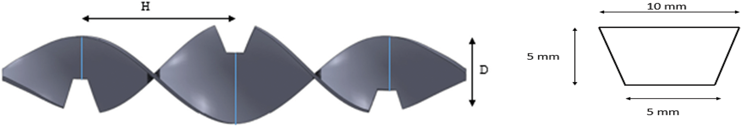
Figure 1: Physical dimensions of the trapezoidal-cut tape
Trapezoidal-cut twisted tapes are 23.5 mm width and 1.5 mm thick strips of aluminum for two different values of twist ratio (y), i.e., y = 6.0 and y = 4.4, where y = H/D. Table 1 gives the calculations of the twist ratio. Full-length trapezoidal-cut twisted tapes of dimensions 5 mm depth, 5 mm base, and 10 mm width is used for the experiment.
A Copper tube, with an internal diameter of 28.5 mm and a longitudinal length of 2000 mm initiates the flow of hot oil which is maintained at 65°C and cold oil maintained at 18°C flows in a counter direction through the annulus. The tube wall is insulated with wool and asbestos rope to reduce heat loss and improve overall heat transfer efficiency (Fig. 2). We want to analyze the flow in a fully developed laminar regime, so we consider the ‘Reynolds Number’ range to vary from 200 to 2000 for the experimental purpose. At 65°C with constant heat flux conditions, the flow rate of hot oil is maintained to vary from 0.277 to 2.77 L/s to attain the laminar flow regime. The flow rate is maintained using a rotameter which indicated the flow rate of hot oil inside the tube (Fig. 3). Reference ‘Nusselt Number’ and friction factor for the laminar regime are expressed as 48/11 and 64/Re, respectively. With a twisted tape insert Nu, f and η can be calculated using correlations 1–2 [14].
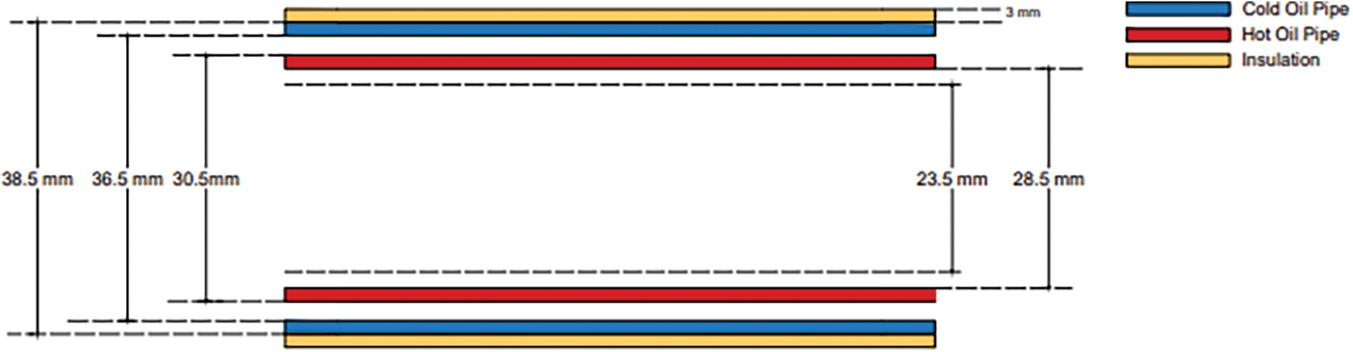
Figure 2: Dimensions of the pipe
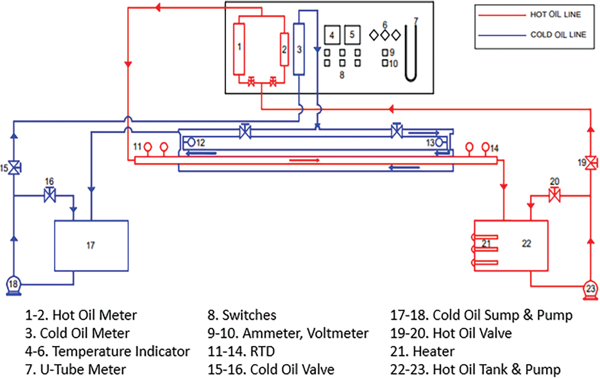
Figure 3: Set-up
3.1 Outcome of an Insert with the Trapezoidal Cut on Heat Transfer
‘Nusselt Number’ is the ratio of convective to the conductive transfer of heat at a layer of boundary in a fluid. ‘Nusselt Number’ over the laminar flow regime is constant for the plain tube and can be calculated as Nu = 48/11 = 4.36. Improvement in ‘Nusselt Number’ by a factor of 35–40 times is observed (Table 2) with tape inserts, which is higher for reducing twist ratio. Fig. 4 indicates that the spiral flow along the length and interrupts the entire pass (flow) of the fluid for an insert with the trapezoidal cut, the Nu is higher than a plain tube, and hence heat transfer rate increases. The maximum rate of heat transfer was given by the smaller twist ratio because turbulence intensity and flow length acquired were maximum for the lower twist ratio.
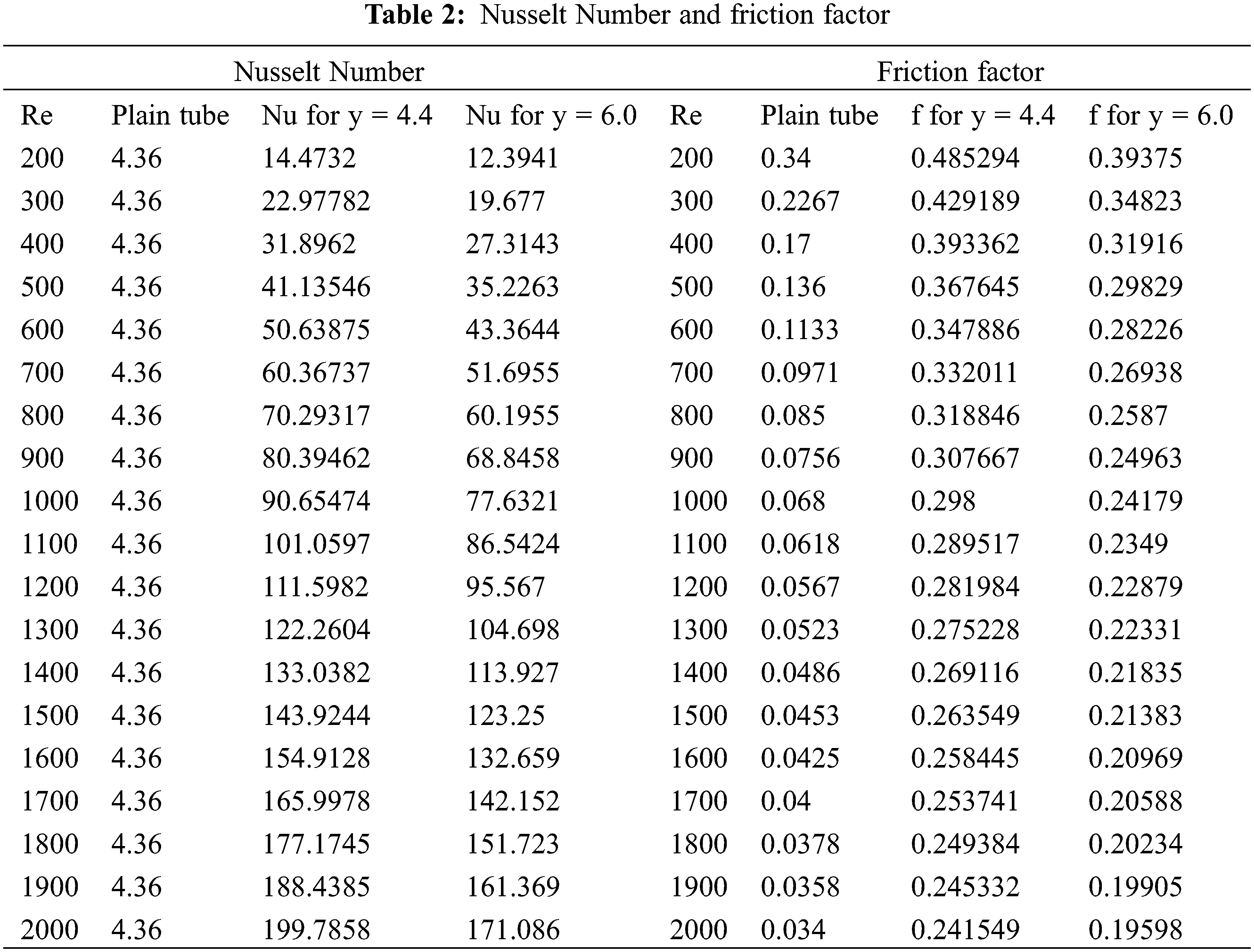
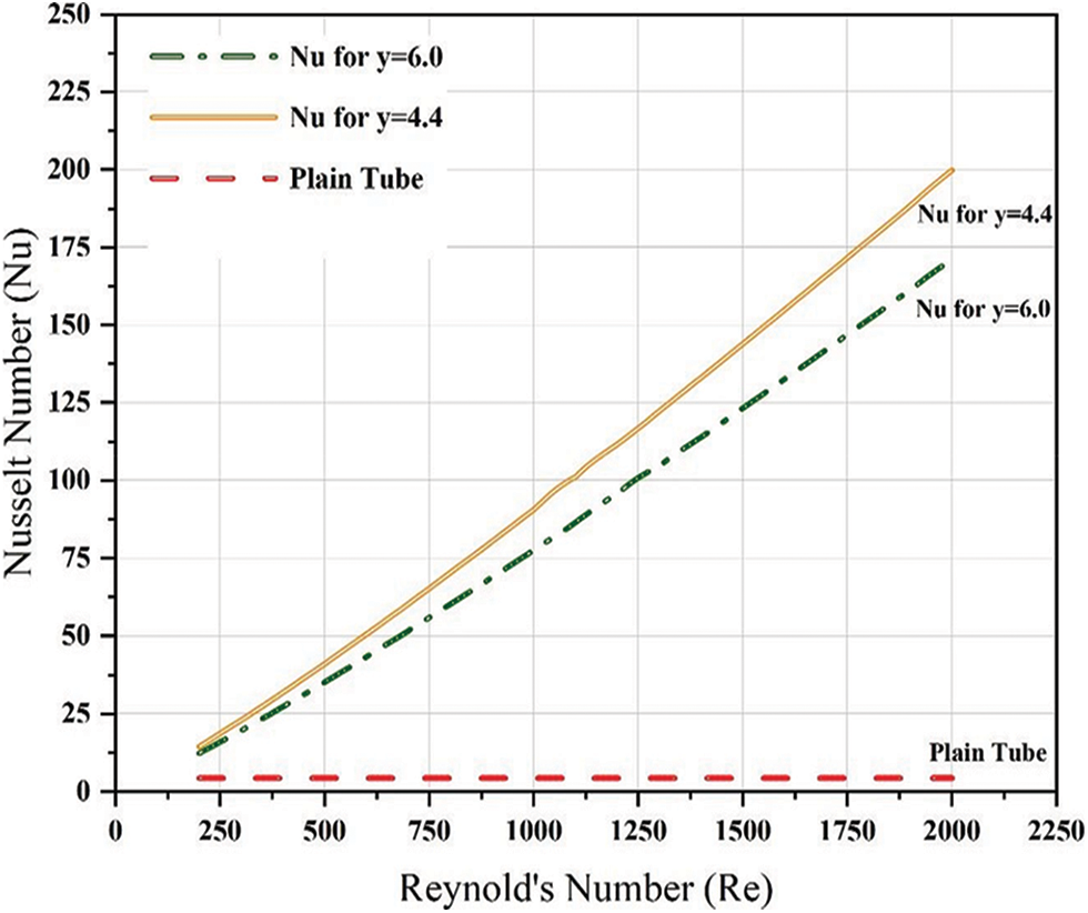
Figure 4: Plot of Nusselt number
3.2 Outcome of an Insert with the Trapezoidal Cut on Friction Factor
The function of Reynold’s Number and relative roughness is called a friction factor. The friction factor is independent of Reynold’s Number at very large Re due to the thickness of the laminar sub-layer decreasing with the increase of Reynold’s Number as shown in Table 2. Fig. 5 represents the friction factor, i.e., heat loss worsens with tape inserts in comparison to plain tubes. Tape insert with a lower twist ratio produces a higher friction factor.
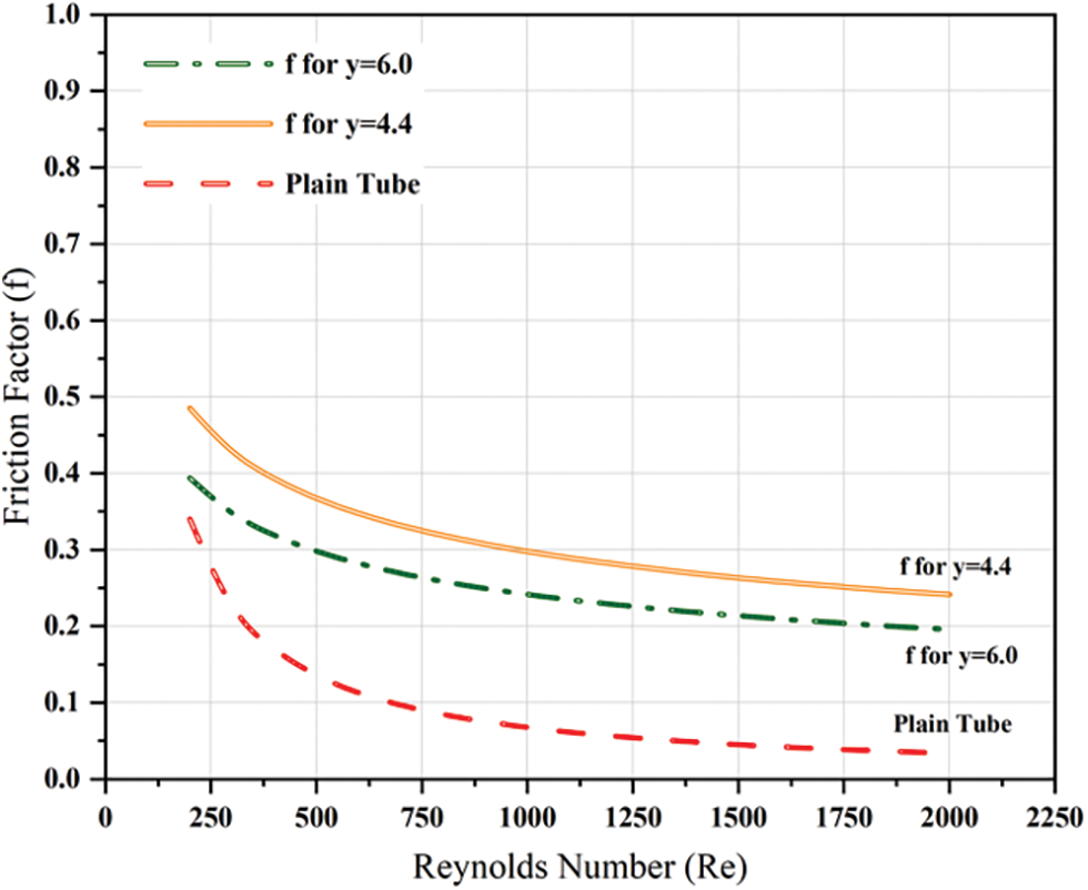
Figure 5: Plot of friction factor
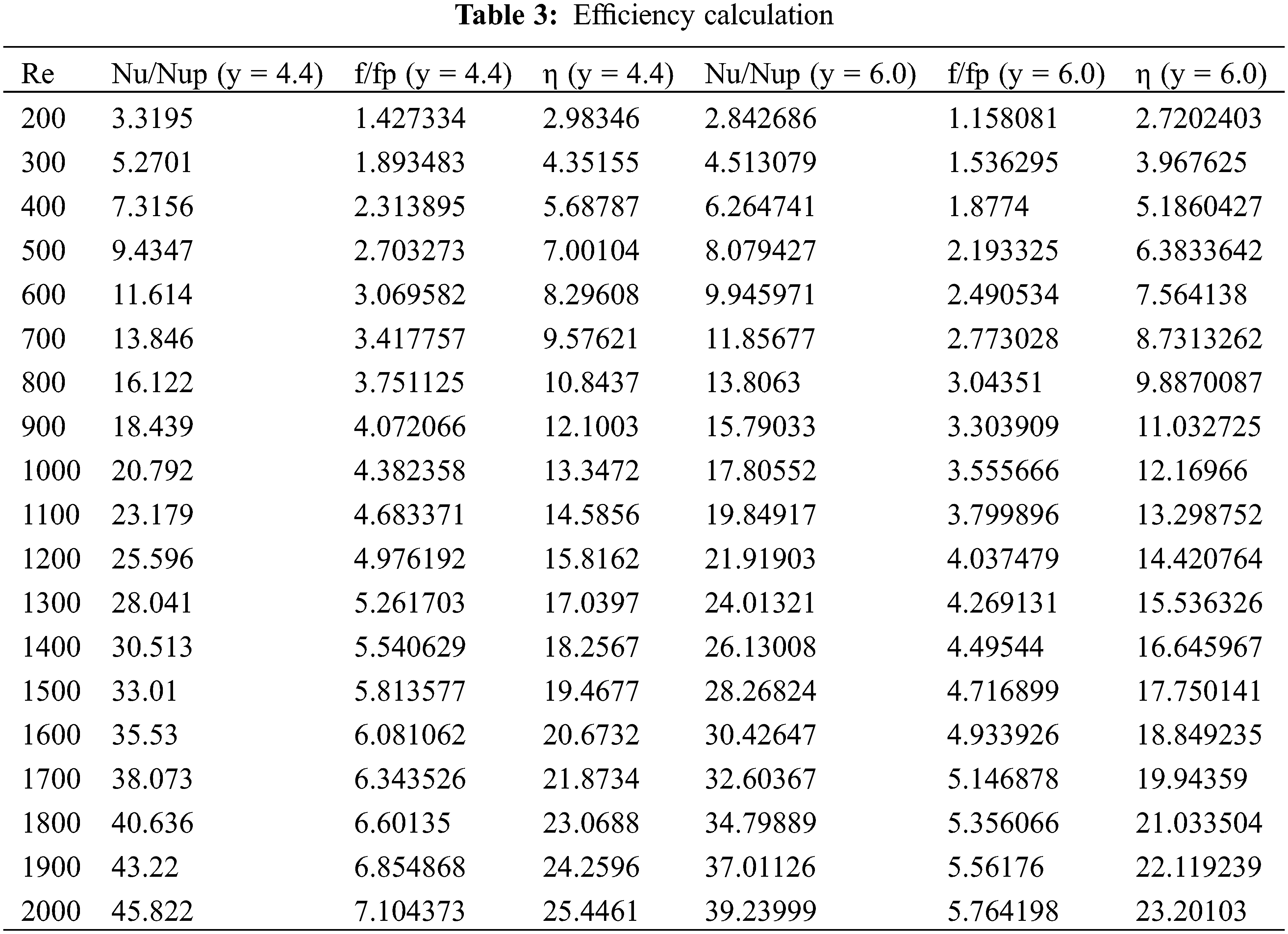
3.3 Outcome of an Insert with the Trapezoidal Cut on the Efficiency of the Heat Exchanger
The thermal efficiency of the trapezoidal-cut tape is analyzed using
The enhancement quality is estimated from Eq. (3). The thermal efficiency variation with Reynold’s Number is plotted in Fig. 6. From Table 3, it can be seen that a trapezoidal cut tape insert with a twist ratio of 4.4 offers better thermal efficiency than a trapezoidal cut tape insert with a twist ratio of 6. Hence, it can be concluded that the lower the twist ratio, the better will be the thermal efficiency. Thermal efficiency is found to be improved by a factor of 69% in comparison to tape inserts with a higher twist ratio.

Figure 6: Plot of efficiency
The major findings of the experiment can be concluded as follows:
1. Over the examined ‘Reynolds Number’ range, tape insert with a lower twist ratio, i.e., y = 4.4 offers a higher value of Nu compared to twisted tape with a higher twist ratio, i.e., y = 6. So, it can be stated that the value of ‘Nusselt Number’ decreases with an increasing twist ratio.
2. For better heat circulation within the system, losses must be minimized. Lower the friction factor lesser will be the heat loss. A plain tube is found to induce a lower friction factor in comparison to tape inserts. It was found that a tape insert with a higher twist ratio offers a lower value of friction factor.
3. Thermal efficiency can be improved by using tape inserts with a smaller twist ratio. It was relatively higher for an insert with the trapezoidal cut with a smaller twist ratio (y = 4.4).
Acknowledgement: For permitting us to experiment, the authors thank the Manager and Assistant Manager of SGP Instruments & Control, Ambernath (E), District-Thane (M.S.)–India.
Funding Statement: The authors received no specific funding for this study.
Conflicts of Interest: The authors declare that they have no conflicts of interest to report regarding the present study.
References
1. Meyer, J. P., Olivier, J. A. (2014). Heat transfer and pressure drop characteristics of smooth horizontal tubes in the transitional flow regime. Heat Transfer Engineering, 35(14–15), 1246–1253. DOI 10.1080/01457632.2013.876793. [Google Scholar] [CrossRef]
2. Rozzi, S., Massini, R., Paciello, G., Pagliarini, G., Rainieri, S. et al. (2007). Heat treatment of fluid foods in a shell and tube heat exchanger: Comparison between smooth and helically corrugated wall tubes. Journal of Food Engineering, 79(1), 249–254. DOI 10.1016/j.jfoodeng.2006.01.050. [Google Scholar] [CrossRef]
3. Liu, S., Sakr, M. (2013). A comprehensive review on passive heat transfer enhancements in pipe exchangers. Renewable and Sustainable Energy Reviews, 19(6), 64–81. DOI 10.1016/j.rser.2012.11.021. [Google Scholar] [CrossRef]
4. Zhang, Z., Ma, D., Fang, X., Gao, X. (2008). Experimental and numerical heat transfer in a helically baffled heat exchanger combined with one three-dimensional finned tube. Chemical Engineering and Processing: Process Intensification, 47(9–10), 1738–1743. DOI 10.1016/j.cep.2007.09.012. [Google Scholar] [CrossRef]
5. Meyer, J. P. (2014). Heat transfer in tubes in the transitional flow regime. Proceedings of the 15th International Heat Transfer Conference, IHTC-15. Kyoto, Japan. DOI 10.1615/ihtc15.kn.000003. [Google Scholar] [CrossRef]
6. Obot, N. T., Esen, E. B., Rabas, T. J. (1990). The role of transition in determining friction and heat transfer in smooth and rough passages. International Journal of Heat and Mass Transfer, 33(10), 2133–2143. DOI 10.1016/0017-9310(90)90115-B. [Google Scholar] [CrossRef]
7. Owen, M. S. (2009). ASHRAE handbook–fundamentals. Atlanta: American Society of Heating, Refrigerating and Air-Conditioning Engineers. [Google Scholar]
8. Cengel, Y. A., Ghajar, A. J. (2015). Heat and mass transfer: Fundamentals & applications. New York: Mcgraw Hill Education. [Google Scholar]
9. Duan, Z., Yovanovich, M. M., Muzychka, Y. S. (2012). Pressure drop for fully developed turbulent flow in circular and noncircular ducts. Journal of Fluids Engineering, 134(6), 1–10. DOI 10.1115/1.4006861. [Google Scholar] [CrossRef]
10. Muzychka, Y. S., Duan, Z. P., Yovanovich, M. M. (2011). Fluid friction and heat transfer in microchannels. In: Handbook of microfluidics and nanofluidics. USA: CRC Press. [Google Scholar]
11. Duan, Z. (2012). New correlative models for fully developed turbulent heat and mass transfer in circular and noncircular ducts. Journal of Heat Transfer, 134(1), 1–6. DOI 10.1115/1.4004855. [Google Scholar] [CrossRef]
12. Saha, S. K., Dutta, A., Dhal, S. K. (2001). Friction and heat transfer characteristics of laminar swirl flow through a circular tube fitted with regularly spaced twisted-tape elements. International Journal of Heat and Mass Transfer, 44(22), 4211–4223. DOI 10.1016/S0017-9310(01)00077-1. [Google Scholar] [CrossRef]
13. Hong, S. W., Bergles, A. E. (1976). Augmentation of laminar flow heat transfer in tubes by means of twisted-tape inserts. Journal of Heat Transfer, 98(2), 251–256. DOI 10.1115/1.3450527. [Google Scholar] [CrossRef]
14. Wongcharee, K., Eiamsa-ard, S. (2011). Friction and heat transfer characteristics of laminar swirl flow through the round tubes inserted with alternate clockwise and counter-clockwise twisted-tapes. International Communications in Heat and Mass Transfer, 38(3), 348–352. DOI 10.1016/j.icheatmasstransfer.2010.12.007. [Google Scholar] [CrossRef]
15. Watanabe, K., Taira, T., Mori, Y. (1983). Heat transfer augmentation in tubular flow by twisted tapes at high temperatures and optimum performance. Heat Transfer-Japanese Research, 12, 1–31. [Google Scholar]
16. Bandyopadhyay, P. S., Gaitonde, U. N., Sukhatme, S. P. (1991). Influence of free convection on heat transfer during laminar flow in tubes with twisted tapes. Experimental Thermal and Fluid Science, 4(5), 577–586. DOI 10.1016/0894-1777(91)90036-Q. [Google Scholar] [CrossRef]
17. Date, A. (1974). Prediction of fully-developed flow containing a twisted-tape. International Journal of Heat and Mass Transfer, 17(8), 845–859. DOI 10.1016/0017-9310(74)90152-5. [Google Scholar] [CrossRef]
18. Date, A. W., Gaitonde, U. N. (1990). Development of correlations for predicting characteristics of laminar flow in a tube fitted with regularly spaced twisted-tape elements. Experimental Thermal and Fluid Science, 3(4), 373–382. DOI 10.1016/0894-1777(90)90035-6. [Google Scholar] [CrossRef]
19. Du Plessis, J. P. (1982). Laminar flow and heat transfer in a smooth tube with a twisted-tape insert (Ph.D. Thesis). University of Stellenbosch, South Africa. [Google Scholar]
20. Tam, L. M., Ghajar, A. J. (1997). Effect of inlet geometry and heating on the fully developed friction factor in the transition region of a horizontal tube. Experimental Thermal and Fluid Science, 15(1), 52–64. DOI 10.1016/S0894-1777(97)00035-6. [Google Scholar] [CrossRef]
21. Reynolds, O. (1883). An experimental investigation of the circumstances which determine whether the motion of water shall be direct or sinuous, and of the law of resistance in parallel channels. Philosophical Transactions of the Royal Society of London, 174(795), 935–982. DOI 10.1098/rstl.1883.0029. [Google Scholar] [CrossRef]
22. Lindgren E. R. (1953). Some aspects of the change between laminar and turbulent flow of liquids in cylindrical tubes. In: Arkiv for fysik, vol. 7, no. 4, pp. 293–308. [Google Scholar]
23. Warke, A. S., Ramesh, K., Mebarek-Oudina, F., Abidi, A. (2021). Numerical investigation of the stagnation point flow of radiative magnetomicropolar liquid past a heated porous stretching sheet. Journal of Thermal Analysis and Calorimetry, 147(12), 6901–6912. DOI 10.1007/s10973-021-10976-z. [Google Scholar] [CrossRef]
24. Alkasassbeh, M., Omar, Z., Mebarek-Oudina, F., Raza, J., Chamkha, A. (2019). Heat transfer study of convective fin with temperature-dependent internal heat generation by hybrid block method. Heat Transfer-Asian Research, 48(4), 1225–1244. DOI 10.1002/htj.21428. [Google Scholar] [CrossRef]
25. Djebali, R., Mebarek-Oudina, F., Rajashekhar, C. (2021). Similarity solution analysis of dynamic and thermal boundary layers: Further formulation along a vertical flat plate. Physica Scripta, 96(8), 85206. DOI 10.1088/1402-4896/abfe31. [Google Scholar] [CrossRef]
26. Marzougui, S., Mebarek-Oudina, F., Magherbi, M., Mchirgui, A. (2022). Entropy generation and heat transport of Cu-water nanoliquid in porous lid-driven cavity through magnetic field. International Journal of Numerical Methods for Heat & Fluid Flow, 32(6), 2047–2069. DOI 10.1108/HFF-04-2021-0288. [Google Scholar] [CrossRef]
27. Guan, Y., Hu, W., Zhang, Y., Song, K., Wang, L. (2020). Numerical study of the intensity correlation between secondary flow and heat transfer of circle tube-finned heat exchanger with vortex generators. Computer Modeling in Engineering & Sciences, 123(1), 237–256. DOI 10.32604/cmes.2020.09141. [Google Scholar] [CrossRef]
28. Maouedj, R., Menni, Y., Inc, M., Chu, Y. M., Ameur, H. et al. (2021). Simulating the turbulent hydrothermal behavior of Oil/MWCNT nanofluid in a solar channel heat exchanger equipped with vortex generators. Computer Modeling in Engineering & Sciences, 126(3), 855–889. DOI 10.32604/cmes.2021.014524. [Google Scholar] [CrossRef]
29. Musonye, F. S., Ndiritu, H., Kinyua, R. (2021). Performance assessment of heat exchangers for process heat integration. Energy Engineering, 118(2), 211–224. DOI 10.32604/EE.2021.013890. [Google Scholar] [CrossRef]
30. Hasan, S. S., Baqir, A. S., Mahood, H. B. (2021). The effect of injected air bubble size on the thermal performance of a vertical shell and helical coiled tube heat exchanger. Energy Engineering, 118(6), 1595–1609. DOI 10.32604/EE.2021.017433. [Google Scholar] [CrossRef]
31. Jia, Y., Wang, J., Shang, L. (2020). Optimization of a heat exchanger using an ARM core intelligent algorithm. Fluid Dynamics & Materials Processing, 16(5), 871–882. DOI 10.32604/fdmp.2020.09957. [Google Scholar] [CrossRef]
32. Tokhtarov, Z., Perov, V., Borisov, V., Tikhomirov, E., Grunina, O. et al. (2022). Experimental investigation of two-phase flow maldistribution in plate heat exchangers. Fluid Dynamics & Materials Processing, 18(4), 1015–1024. DOI 10.32604/fdmp.2022.019534. [Google Scholar] [CrossRef]
33. Jradi, R., Marvillet, C., Jeday, M. (2022). Application of an artificial neural network method for the prediction of the tube-side fouling resistance in a shell-and-tube heat exchanger. Fluid Dynamics & Materials Processing, 18(5), 1511–1519. DOI 10.32604/fdmp.2022.021925. [Google Scholar] [CrossRef]
34. Plant, R., Saghir, M. Z. (2019). Implementation of micro encapsulated phase change material (MEPCM) into fluid based heat exchangers. The International Conference on Computational & Experimental Engineering and Sciences, 21(1), 18. DOI 10.32604/icces.2019.04980. [Google Scholar] [CrossRef]
35. Song, K. N. (2012). Effect of weld properties on the thermo-mechanical structural analysis of prototype process heat exchanger. Structural Durability & Health Monitoring, 8(3), 209–222. DOI 10.32604/sdhm.2012.008.209. [Google Scholar] [CrossRef]
Cite This Article
 Copyright © 2023 The Author(s). Published by Tech Science Press.
This work is licensed under a Creative Commons Attribution 4.0 International License , which permits unrestricted use, distribution, and reproduction in any medium, provided the original work is properly cited.
 Downloads
 Citation Tools