
 Submit a Paper
 Propose a Special lssue
 Open Access
ARTICLE
Analysis of a Stagnation Point Flow with Hybrid Nanoparticles over a Porous Medium
1
Department of Mathematics, Davangere University, Shivagangothri, Davangere, India
2
Department of Mechanical Engineering, Ferdowsi University of Mashhad, Mashhad, Iran
* Corresponding Authors: M. Hatami. Email: ;
Fluid Dynamics & Materials Processing 2023, 19(2), 541-567. https://doi.org/10.32604/fdmp.2022.022002
Received 16 February 2022; Accepted 25 April 2022; Issue published 29 August 2022
 View Full Text
 Download PDF
Abstract
The unsteady stagnation-point flow of a hybrid nanofluid over a stretching/shrinking sheet embedded in a porous medium with mass transpiration and chemical reactions is considered. The momentum and mass transfer problems are combined to form a system of partial differential equations, which is converted into a set of ordinary differential equations via similarity transformation. These ordinary differential equations are solved analytically to obtain the solution for velocity and concentration profiles in exponential and hypergeometric forms, respectively. The concentration profile is obtained for four different cases namely constant wall concentration, uniform mass flux, general power law wall con-centration and general power law mass flux. The effect of different physical parameters such as Darcy number (Da-1), mass transpiration parameter (VC), stretching/shrinking parameter (d), chemical reaction parameter (β) and Schmidt number (SC) velocity and concentration profile is examined. Results show that, the axial velocity will decreases as the shrinking sheet parameter increases, regardless of whether the suction or injection case is examined. The concentration decreases with an increase in the shrinking sheet parameter and the chemical reaction rate parameter.Keywords
Nomenclature
| | Constants |
| | Concentration field |
| | Molecular diffusivity |
| | Inverse Darcy number |
| | Chemical reaction parameter |
| | Permeability of porous medium |
| | Pressure |
| | Schmidt number |
| | Suction/injection parameter |
| | Mass transfer velocity |
| | Velocities along |
| | Cartesian coordinates |
| Greek symbols | |
| | Chemical reaction parameter |
| | Similarity variable |
| | Dynamic viscosity |
| | Kinematic viscosity |
| | Density |
| Subscripts | |
| | Hybrid nanofluid parameter |
| | Wall condition |
| | Ambient condition |
| Abbreviations | |
| HNF | Hybrid nanofluid |
| MHD | Magneto hydrodynamics |
| ODEs | Ordinary differential equations |
| PDEs | Partial differential equations |
| PST | Prescribed surface temperature |
| PHF | Prescribed heat flux |
Highlights
• This work investigates the unsteady stagnation point flow and mass transfer with chemical reaction.
• The system of partial differential equations is converted into system of ordinary differential equations via similarity transformations.
• The concentration profile is obtained for cases such as constant wall concentration, uniform mass flux, general power law wall concentration and general power law mass flux.
• The axial velocity decreases as the shrinking sheet parameter increases.
The mass transfer and momentum boundary layer flow have practical interest in the field of polymer process and electrochemistry. Also, the hybrid nanofluid (HNF) flow is a significant field in industry and become an interest field for researchers due to its wide applications. There are many significances of heat transfer over stretching sheet, due to its advantages mentioned by many researchers [1,2]. Aly et al. [3,4] made a comparison between the significances of HNF over NF for the magneto-hydrodynamic (MHD) flow and heat transfer by considering the effect of partial slip. Turkyilmazoglu [5] found the multiple solutions for MHD slip flow of viscoelastic fluid and Anusha et al. [6,7] investigated the unsteady inclined MHD flow for Casson fluid with hybrid nanoparticles in a porous media. Also, Mahabaleshwar et al. [8] investigated the MHD flow behaviour and mass transfer due to porous media. Fang et al. [9] examined the unsteady stagnation point flow and heat transfer to obtain the closed form solutions for prescribed wall temperature and wall heat flux. Mahabaleshwar et al. [10,11] made a research on the MHD flow with carbon nanotubes by considering the effect of mass transpiration and radiation on it. Suresh et al. [12,13] investigated the effect of hybrid nanofluid on heat transfer characteristics and observed that a hybrid nanofluid of (Al2O3-Cu/H2O) had significant heat transfer. Momin [14] investigated the laminar flow in an elevated funnel using mixed convection with a (Al2O3-Cu/H2O) hybrid nanofluid. Recently, the mixed convective flow with radiation is studied by Patil et al. [15] considering the couple stress fluid flow for first order chemical reaction. Furthermore, Mahabaleshwar et al. [16] examined the MHD non-Newtonian fluid flow and heat transfer due to porous surface with heat source/sink by different solution methods. Mahabaleshwar et al. [17] investigated the steady flow with HNF with mass suction, mathematically, and found the solution in algebraic decaying form. Nakhchi et al. [18,19] studied the effect of CuO-water nanofluid on the improvement of entropy production for a double pipe heat exchanger and a double V-cut twisted tapes, respectively. Recently many works are done on HNF flow by researchers such as Zainal et al. [20] on MHD flow due to quadratic stretching/shrinking sheet, Umair et al. [21] on radiative mixed convective flow, more recent developments and applications of HNF are investigated by Sarkar et al. [22], Vishalakshi et al. [23] studied the effect of slips and mass transpiration on the flow over porous sheet and Sneha et al. [24] on dusty HNF. The effect of nanoparticles on the flow is also investigated by Jalali et al. [25] and Bhandari [26].
Motivated by these investigations, the current work investigates the unsteady stagnation point flow of
The incompressible unsteady stagnation point flow over stretching/shrinking sheet is embedded in porous media with mass transpiration and mass transfer with chemical reaction as shown in Fig. 1. The
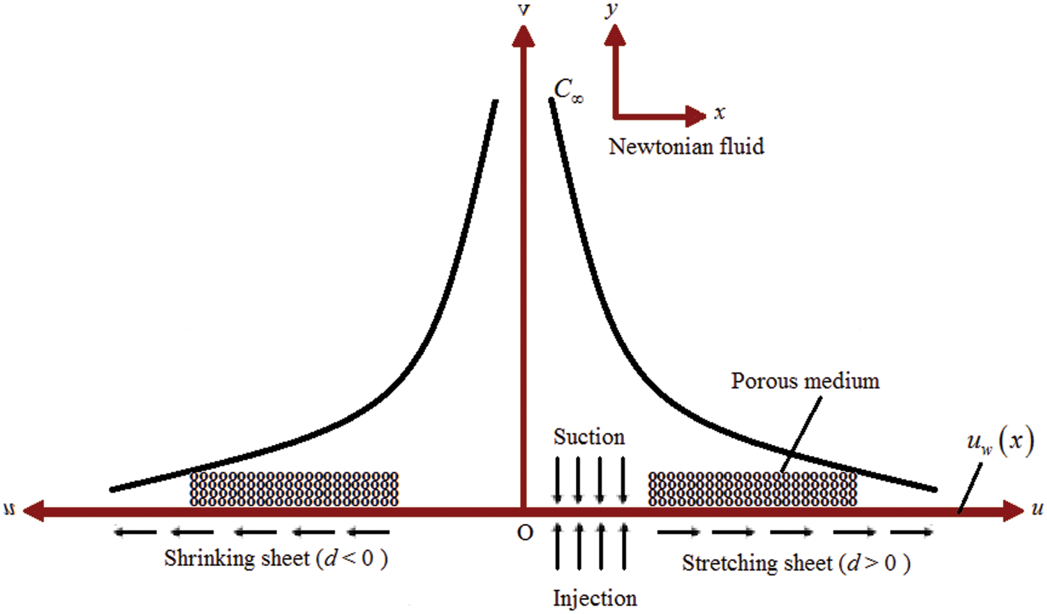
Figure 1: Schematic diagram of the problem
and the boundary conditions (B.Cs) are,
The following similarity transformation is introduced (see Fang et al. [9]) to transform the system of PDEs (1) to (4) into system of ODEs in order to find out the analytical solution,
And therefore the velocities along x- and y-axes are obtained as,
and wall mass transpiration velocity is,
On applying x-momentum with
Use Eqs. (7), (8) and (10) in Eqs. (2) and (4) to get,
The B.Cs associated with this Eqs. (5) and (6) also reduced as
here,
Also,
Since
and
where,
On differentiate Eq. (16) w.r.t x to obtain equation as
The pressure
where,
Consider a special case with
Defining a new transformation
And the associated B.Cs will reduces as,
Assume the solution of Eq. (22) is in the form,
On applying B.Cs defined in Eq. (23),
And on using Eqs. (24) and (25) in Eq. (22) will give,
Its roots will obtained as,
here, to obtain physically feasible solution Eq. (27) must satisfy
The solution will become,
And axial velocity is given by
2.3 Solution for Concentration
For the special case
Use Eq. (29) in above,
Then use Eq. (28) in above,
On introducing the new variable
And the B.Cs in terms of new variable are,
Then the general solution of Eq. (33) in terms of
And Eq. (35) in terms of
To obtain value of constant
where,
then wall mass flux is given by,
Define the transformation for Eq. (4) as,
Use Eq. (40) in Eq. (4) for
With B.Cs,
The Eq. (41) is similar to Eq. (31b) upto their general solution,
On using B.Cs as in Eq. (42), Eq. (43) will imply.
2.5 General Power Law Wall Concentration
In the current section we examined the general condition by assuming the wall concentration with a power law dependence on both time and distance as
by applying this new definition in Eq. (4) to obtain the following ODE for
With the following B.Cs,
For
By introducing new variable
where,
And the B.Cs will reduce to,
Now define
Here
Eq. (51) is the standard form of hypergeometric differential equation and its solution will be in the form of,
It gives the solution of Eq. (49) in the form,
And the wall mass flux is,
2.6 General Power-Law Mass Flux
In this section, the general condition is assumed with the wall concentration by a power law dependence on both time and distance
Use Eq. (56) in Eq. (4) for
With B.Cs as,
Eq. (57) is the same as Eq. (46), therefore their solutions are similar. We can obtain the solution of Eq. (57) as,
On applying B.C as in Eq. (58) to Eq. (59), we obtain the solution of Eq. (57) as follows:
The current work with nanoparticles dispersed in the base fluid is well agreement with the investigation of Fang et al. [9] in the absence of nanoparticles, porous media, stagnation point parameter and chemical reaction parameter.
The examination of unsteady stagnation point flow over porous media with mass transpiration and mass transfer with chemical reaction for
Fig. 2 demonstrates the solution domain
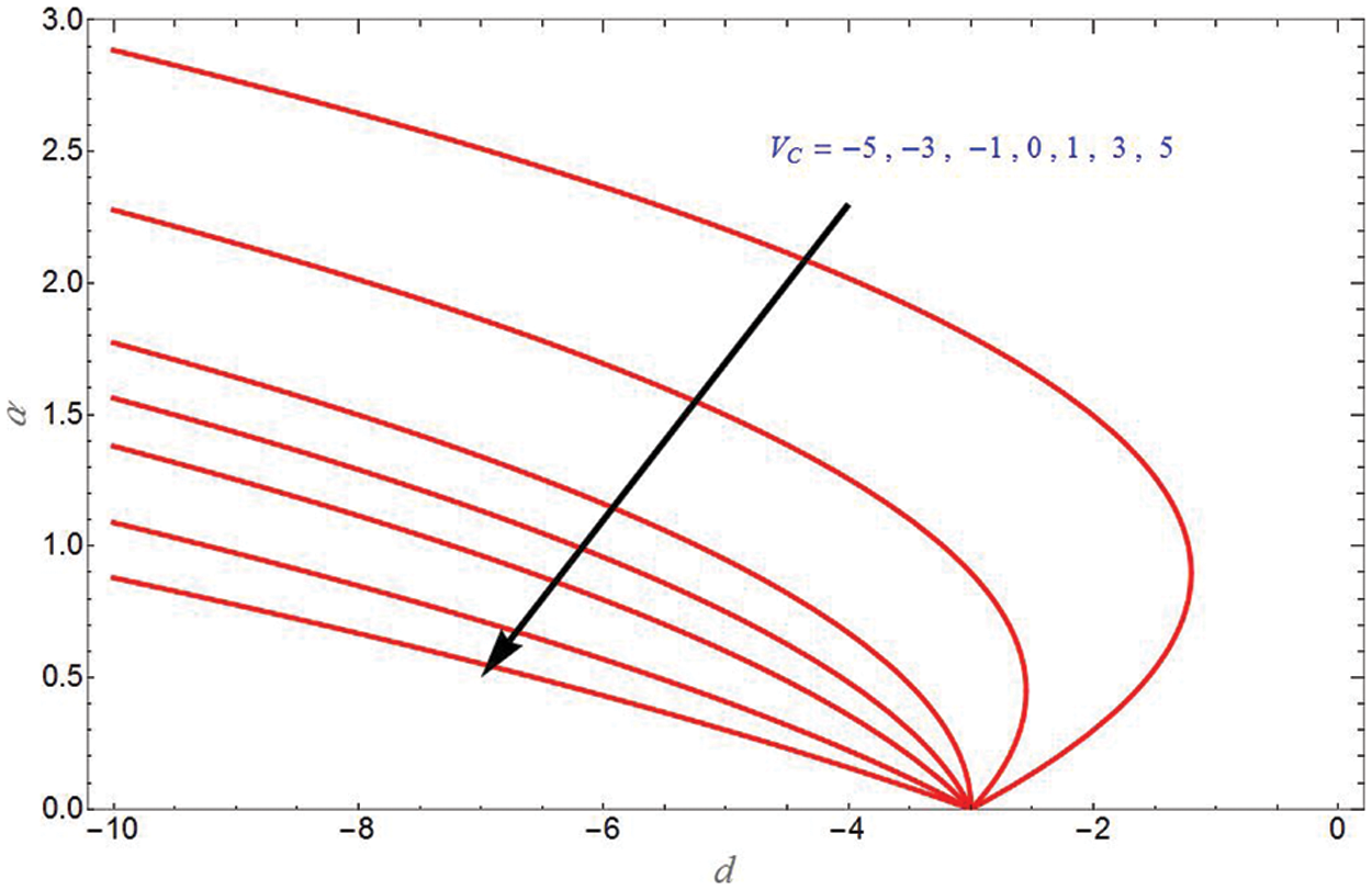
Figure 2:
Fig. 3 depicts the transverse velocity due to stretching sheet and different values of
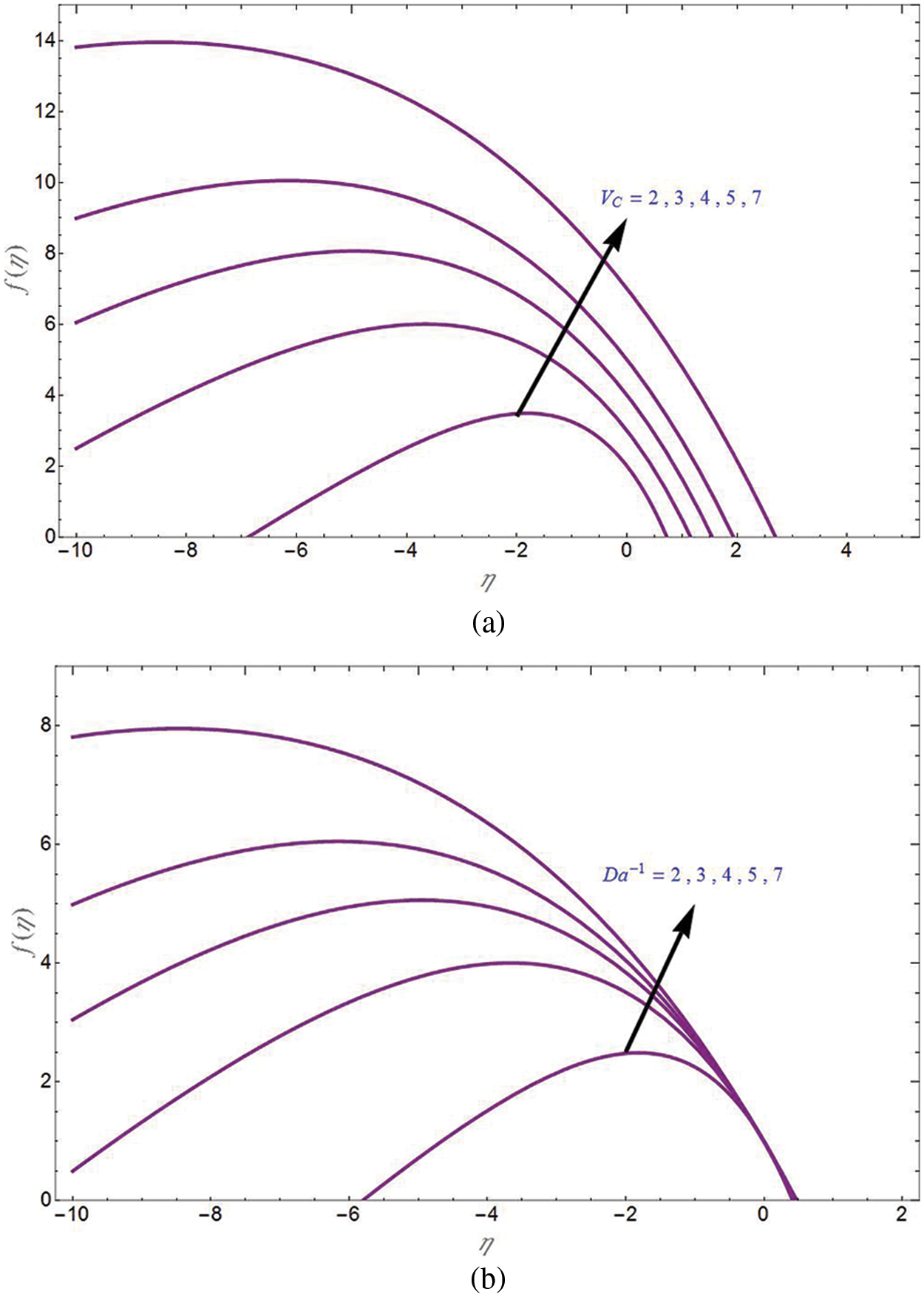
Figure 3: Transverse velocity
Fig. 4a is the plot for axial velocity due to shrinking sheet
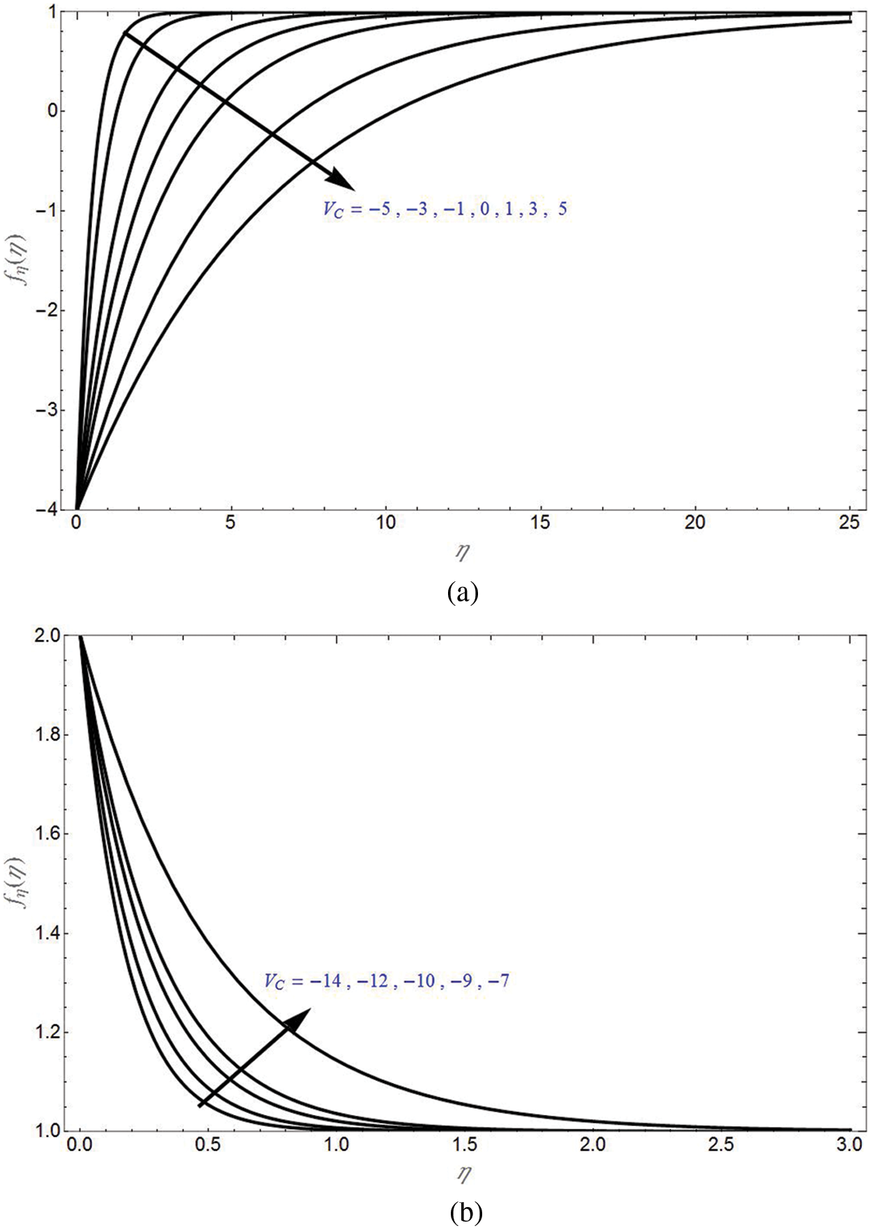
Figure 4: Axial velocity
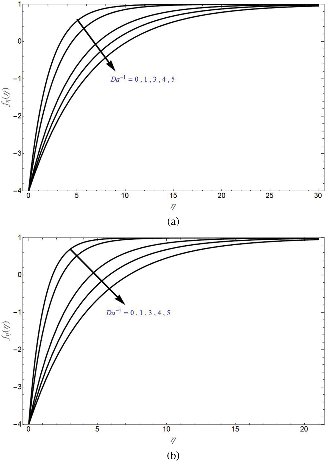
Figure 5: Axial velocity

Figure 6: Axial velocity
The concentration profiles for different values of shrinking sheet parameter are demonstrated in Fig. 7 for suction and non-permeability cases in Figs. 7a and 7b, respectively. It can be seen that
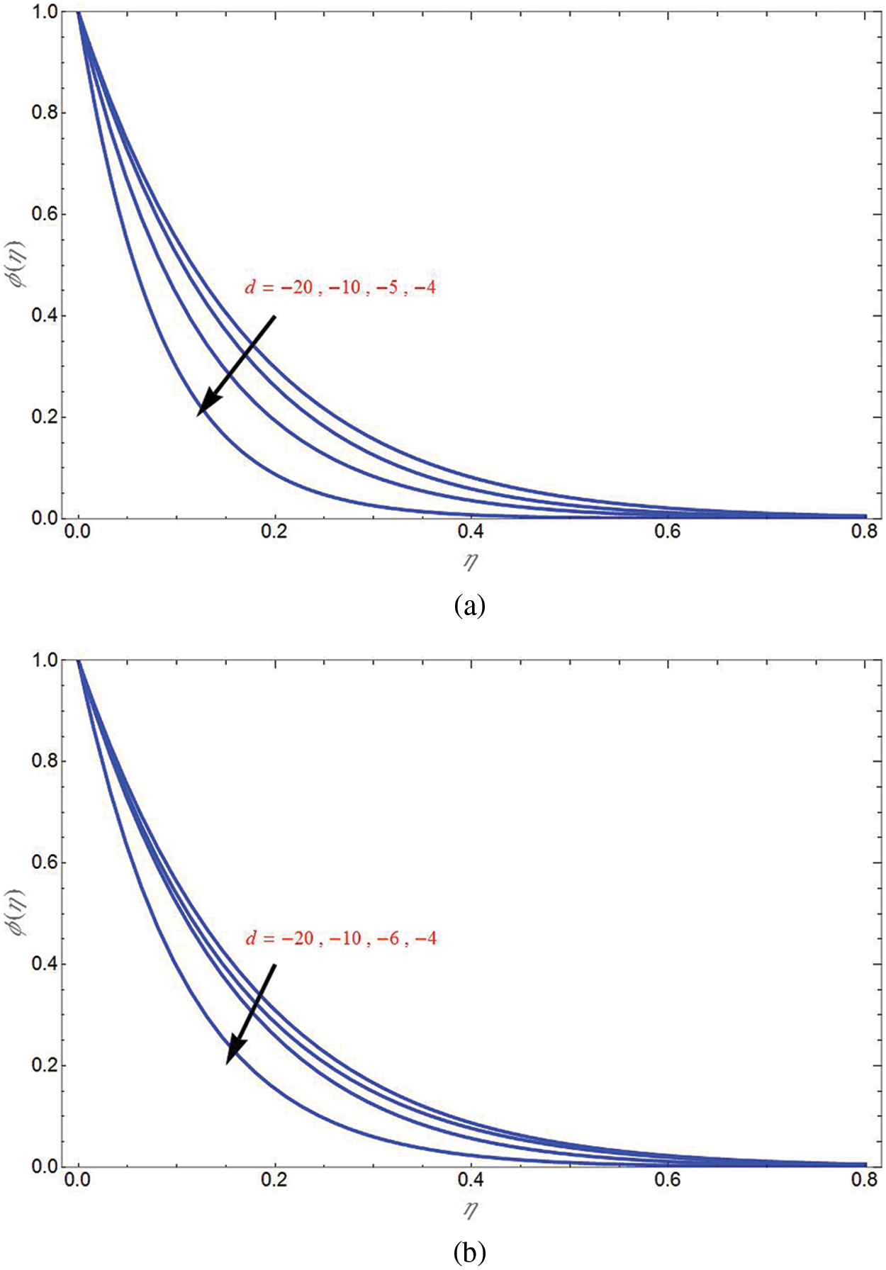
Figure 7: Concentration profile
The concentration profile for different values of

Figure 8: Concentration profile
The concentration profile for different values of mass transpiration parameter due to shrinking sheet

Figure 9: Concentration profile
The concentration profile of mass flux case for different values of shrinking sheet parameter is demonstrated in Fig. 10 for suction, non-permeability and injection cases, respectively in Figs. 10a–10c. It can be seen that
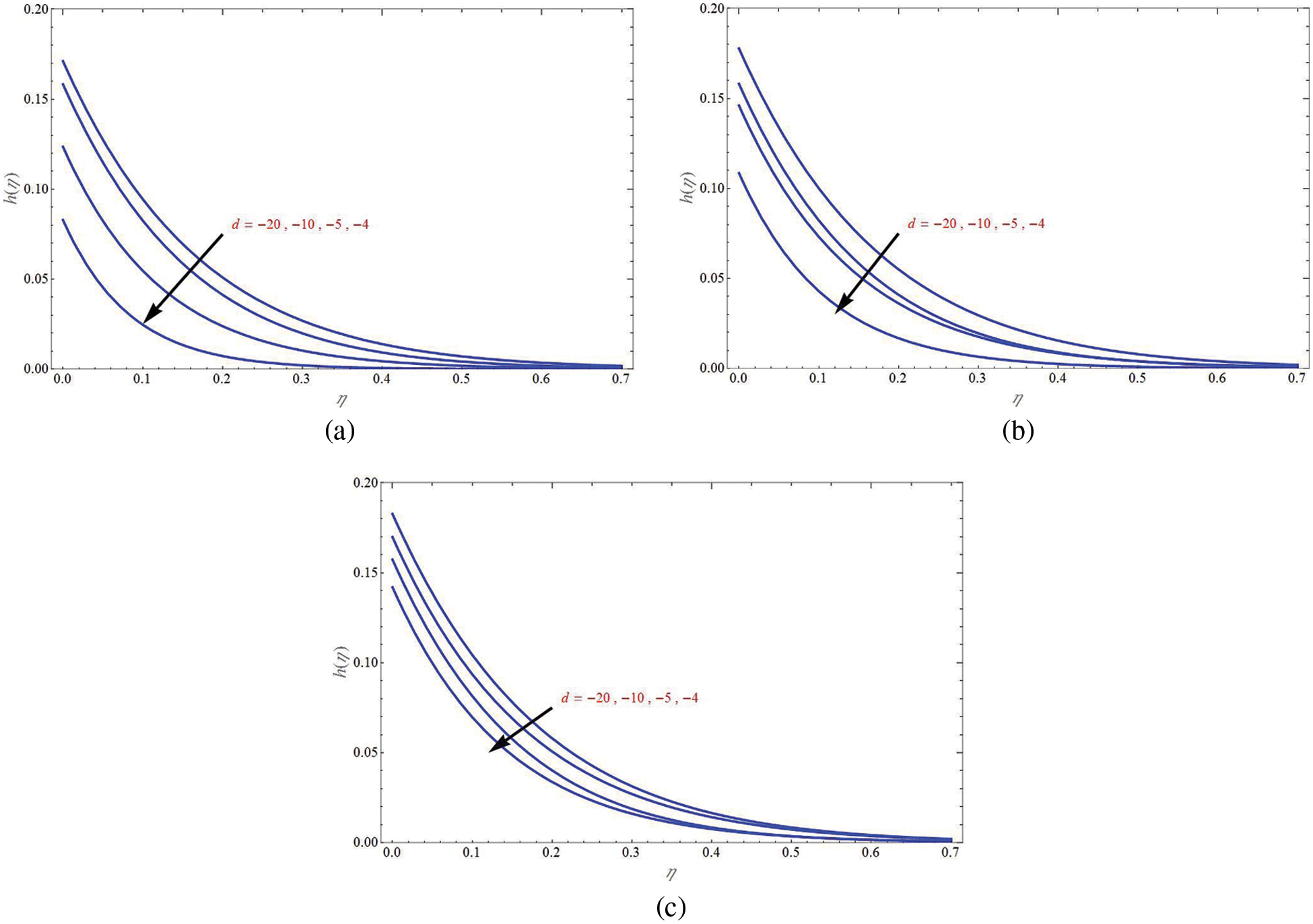
Figure 10: Concentration profile
The concentration profile of mass flux case for different values of
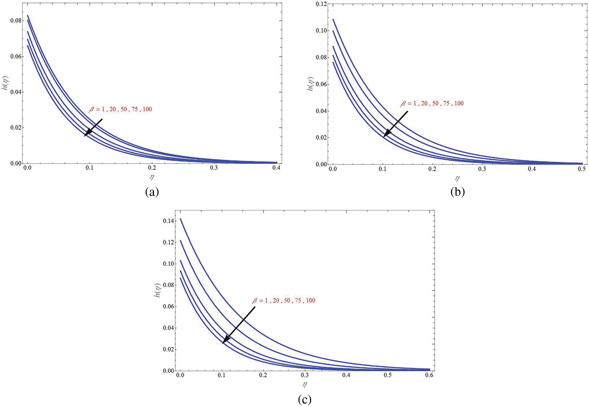
Figure 11: Concentration profile
The concentration profile of mass flux case for different values of mass transpiration parameter due to shrinking sheet
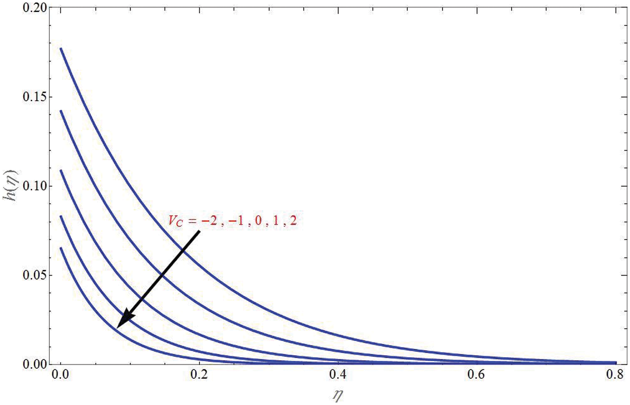
Figure 12: Concentration profile
The concentration profile of mass flux case for different values of

Figure 13: Concentration profile
The concentration profile of mass flux case for different values of

Figure 14: Concentration profile
Fig. 15 shows the general power law wall concentration profile for different values of shrinking sheet parameter for suction, non-permeability and injection cases in Figs. 15a–15c, respectively. It can be seen that

Figure 15: General power law wall concentration profile
Furthermore, Fig. 16 demonstrates the general power law wall concentration profile for different values of
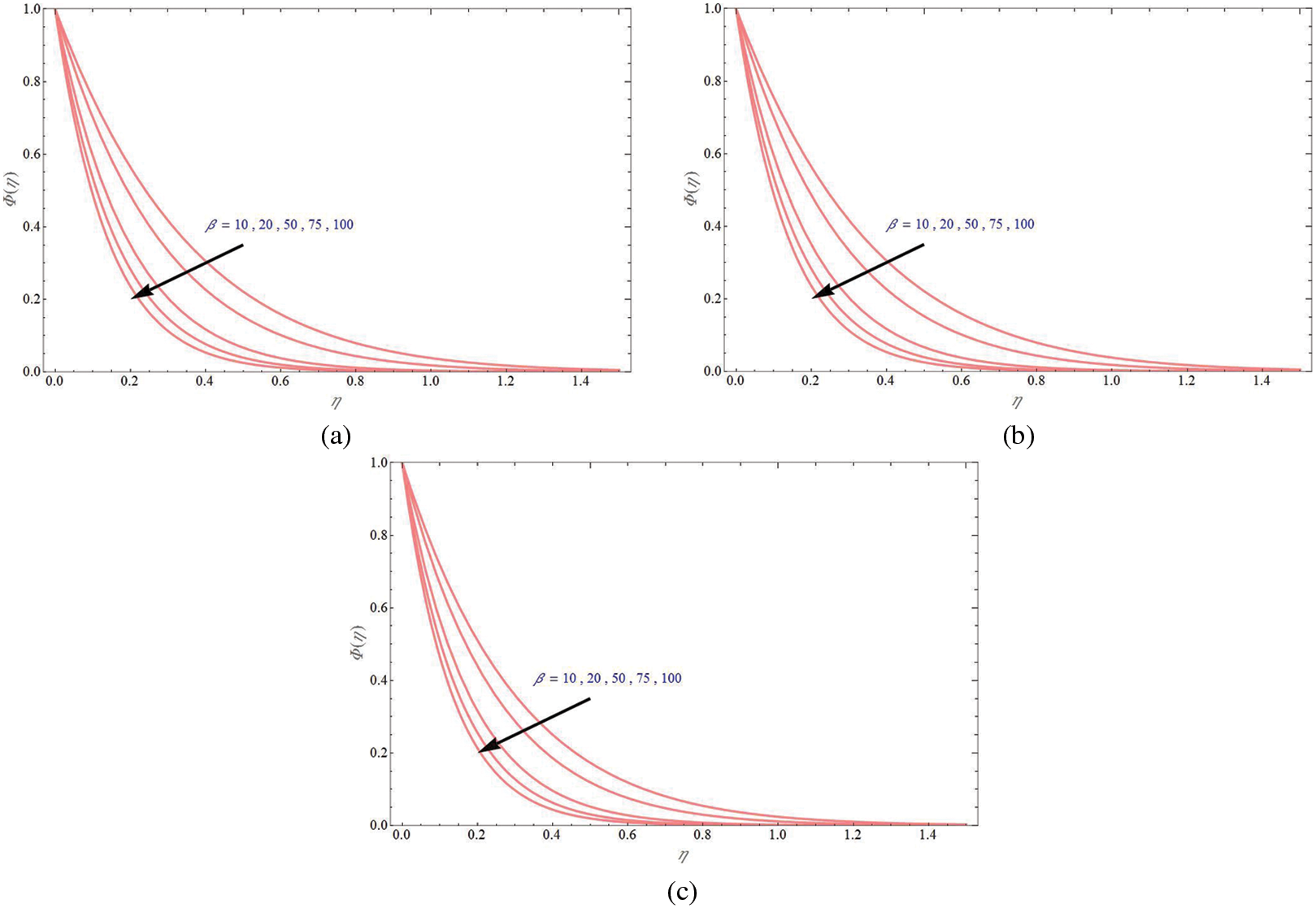
Figure 16: General power law wall concentration profile
The general power law wall concentration profile for different values of mass transpiration parameter due to shrinking sheet

Figure 17: The general power law wall concentration profile
The general power law wall concentration profile for different values of

Figure 18: The general power law wall concentration profile
Finally, Figs. 19 and 20 demonstrate the stream line graphs for upper branch solution and lower branch solution, respectively for some values of time t = 0.1, 0.5, 1. Stretching velocity of the wall is away from the origin since stream velocity is towards the origin. It can be seen that as the time increases, the stagnation point is moving away from the origin and towards the positive y direction.

Figure 19: Stream line graphs for upper branch solution keeping VC = −6, d = −1, K = 1, in (a)

Figure 20: Stream line graphs for lower branch solution keeping
The current work examined the unsteady stagnation point HNF flow over porous sheet with mass transpiration and mass transfer with chemical reaction. The momentum and mass transfer problem are solved analytically to obtain the solution for velocity and concentration profiles in exponential form and hypergeometric form respectively. The concentration profile is obtained for four different cases such as constant wall concentration, uniform mass flux, general power law wall concentration and general power law mass flux. The effect of different physical parameters like Darcy number
• The solution domain will expand as mass transpiration decreases for shrinking sheet case.
• Transverse velocity increases with increase in
• Axial velocity decreases with increase in mass transpiration and it decreases with increase in
• The axial velocity will decrease as the shrinking sheet parameter increases both in suction and injection cases.
• Concentration profile
• The concentration profile of mass flux case
• Injection case had more mass transfer than suction case.
• The general power law wall concentration profile
Acknowledgement: The author T. Anusha is thankful to Council of Scientific and Industrial Research (CSIR), New Delhi, India for financial support in the form of Junior Research Fellowship: File No. 09/1207(0003)/2020-EMR-I.
Funding Statement: The authors received no specific funding for this study.
Conflicts of Interest: The authors declare that they have no conflicts of interest to report regarding the present study.
References
1. Crane, L. J. (1970). Flow past a stretching plate. Zeitschrift für angewandte Mathematik und Physik ZAMP, 21(4), 645–647. DOI 10.1007/BF01587695. [Google Scholar] [CrossRef]
2. Wang, C. Y. (1984). The three-dimensional flow due to a stretching flat surface. Physics of Fluids, 27, 1915–1917. [Google Scholar]
3. Aly, E. H., Pop, I. (2020). MHD flow and heat transfer near stagnation point over a stretching/shrinking surface with partial slip and viscous dissipation: Hybrid nanofluid versus nanofluid. Powder Technology, 367(1), 192–205. DOI 10.1016/j.powtec.2020.03.030. [Google Scholar] [CrossRef]
4. Aly, E. H., Pop, I. M. (2019). MHD flow and heat transfer over a permeable stretching/shrinking sheet in a hybrid nanofluid with a convective boundary condition. International Journal of Numerical Methods for Heat and Fluid Flow, 29(9), 3012–3038. DOI 10.1108/HFF-12-2018-0794. [Google Scholar] [CrossRef]
5. Turkyilmazoglu, M. (2011). Multiple solutions of heat and mass transfer of MHD slip flow for the viscoelastic fluid over a stretching sheet. International Journal of Thermal Sciences, 50(11), 2264–2276. DOI 10.1016/j.ijthermalsci.2011.05.014. [Google Scholar] [CrossRef]
6. Anusha, T., Huang, H. N., Mahabaleshwar, U. S. (2021). Two dimensional unsteady stagnation point flow of Casson hybrid nanofluid over a permeable flat surface and heat transfer analysis with radiation. Journal of Taiwan Institute of Chemical Engineers, 127(8), 79–91. DOI 10.1016/j.jtice.2021.08.014. [Google Scholar] [CrossRef]
7. Anusha, T., Mahabaleshwar, U. S., Sheikhnejad, Y. (2021). An MHD of nanofluid flow over a porous stretching/shrinking plate with mass transpiration and Brinkman ratio. Transport in Porous Media, 142(1–20), 333–352. DOI 10.1007/s11242-021-01695-y. [Google Scholar] [CrossRef]
8. Mahabaleshwar, U. S., Anusha, T., Hatami, M. (2021). The MHD Newtonian hybrid nanofluid flow and mass transfer analysis due to super-linear stretching sheet embedded in porous medium. Scientific Reports, 11(1), 1–17. DOI 10.1038/s41598-021-01902-2. [Google Scholar] [CrossRef]
9. Fang, T. G., Wang, F. J. (2020). Momentum and heat transfer of a special case of the unsteady stagnation point flow. Applied Mathematics and Mechanics, 41(1), 51–82. DOI 10.1007/s10483-020-2556-9. [Google Scholar] [CrossRef]
10. Mahabaleshwar, U. S., Sneha, K. N., Huang, H. N. (2021). An effect of MHD and radiation on CNTS-water based nanofluid due to a stretching sheet in a Newtonian fluid. Case Studies in Thermal Engineering, 28(2), 101462. DOI 10.1016/j.csite.2021.101462. [Google Scholar] [CrossRef]
11. Siddheshwar, P. G., Mahabaleshwar, U. S., Andersson, H. I. (2013). A new analytical procedure for solving the non-linear differential equation arising the stretching sheet problem. International Journal of Applied Mechanics and Engineering, 18(3), 955–964. [Google Scholar]
12. Suresh, S., Venkitaraj, K., Selvakumar, P., Chandrasekar, M. (2012). Effect of Al2O3–Cu/water hybrid nanofluid in heat transfer. Experimental Thermal and Fluid Science, 38, 54–60. [Google Scholar]
13. Suresh, S., Venkitaraj, K., Selvakumar, P., Chandrasekar, M. (2011). Synthesis of Al2O3–Cu/water hybrid nanofluids using two step method and its thermo physical properties. Colloids and Surface A, 388, 41–48. [Google Scholar]
14. Momin, G. G. (2013). Experimental investigation of mixed convection with water-Al2O3 & hybrid nanofluid in inclined tube for laminar flow. International Journal of Scientific and Technology Research, 2, 195–202. [Google Scholar]
15. Mallikarjun, P., Murthy, R. V., Mahabaleshwar, U. S., Lorenzini, G. (2019). Numerical study of mixed convective flow of a couple stress fluid in a vertical channel with first order chemical reaction and heat generation/absorption. Mathematical Modelling of Engineering Problems, 6(2), 175–182. [Google Scholar]
16. Mahabaleshwar, U. S., Vishalakshi, A. B., Azese, M. N. (2022). The role of Brinkman ratio on non-Newtonian fluid flow due to a porous shrinking/stretching sheet with heat transfer. European Journal of Mechanics–B Fluids, 92, 153–165. [Google Scholar]
17. Mahabaleshwar, U. S., Vishalakshi, A. B., Andersson, H. I. (2022). Hybrid nanofluid flow past a stretching/shrinking sheet with thermal radiation and mass transpiration. Chinese Journal of Physics, 75, 152–168. [Google Scholar]
18. Nakhchi, M. E., Hatami, M., Rahmati, M. (2021). Effects of CuO nano powder on performance improvement and entropy production of double-pipe heat exchanger with innovative perforated turbulators. Advanced Powder Technology, 32, 3063–3074. [Google Scholar]
19. Nakhchi, M. E., Esfahani, J. A. (2021). Numerical investigation of turbulent CuO-water nanofluid inside heat exchanger enhanced with double V-cut twisted tapes. Journal of Thermal Analysis and Calorimetry, 145, 2535–2545. [Google Scholar]
20. Zainal, N. A., Nazar, R., Naganthran, K., Pop, I. M. (2020). Stability analysis of MHD hybrid nanofluid flow over a stretching/shrinking sheet with quadratic velocity. Alexandria Engineering Journal, 60, 915–926. [Google Scholar]
21. Khan, U., Shafiq, A., Zaib, A., Baleanu, D. (2020). Hybrid nanofluid on mixed convective radiative flow from an irregular variably thick moving surface with convex and concave effects. Case Studies in Thermal Engineering, 21, 100660. [Google Scholar]
22. Sarkar, J., Ghosh, P., Adil, A. (2015). A review on hybrid nanofluids: Recent research, development and applications. Renewable and Sustainable Energy Reviews, 43, 164–177. [Google Scholar]
23. Vishalakshi, A. B., Mahabaleshwar, U. S., Sarris, I. E. (2022). An MHD fluid flow over a porous stretching/shrinking sheet with slips and mass transpiration. Micromachines, 13(1), 116. [Google Scholar]
24. Sneha, K. N., Mahabaleshwar, U. S., Bennacer, R., Ganaoui, M. E. L. (2021). Darcy Brinkman equations for hybrid dusty nanofluid flow with heat transfer and mass transpiration. Computation, 9(11), 118. [Google Scholar]
25. Jalali, H., Abbassi, H. (2020). Analysis of the influence of viscosity and thermal conductivity on heat transfer by Al2O3-water nanofluid. Fluid Dynamics and Materials Processing, 16(2), 181–198. DOI 10.32604/fdmp.2020.07804. [Google Scholar] [CrossRef]
26. Bhandari, A. (2019). Radiation and chemical reaction effects on nanofluid flow over a stretching sheet. Fluid Dynamics and Materials Processing, 15(5), 557–582. DOI 10.32604/fdmp.2019.04. [Google Scholar] [CrossRef]
Cite This Article
 Copyright © 2023 The Author(s). Published by Tech Science Press.
This work is licensed under a Creative Commons Attribution 4.0 International License , which permits unrestricted use, distribution, and reproduction in any medium, provided the original work is properly cited.
 Downloads
 Citation Tools