
 Submit a Paper
 Propose a Special lssue
 Open Access
ARTICLE

Analysis and Optimization of Flow-Guided Structure Based on Fluid-Structure Interaction
1
Key Laboratory of Intelligent Equipment Digital Design and Process Simulation, Hebei Province, Tangshan University, Tangshan,
063000, China
2
Department of Intelligent Manufacturing, Tangshan Vocational College of Science and Technology, Tangshan, 063001, China
3
Beijing Materials Handling Research Instituted Co., Ltd., Beijing, 100010, China
* Corresponding Author: Yue Cui. Email:
(This article belongs to the Special Issue: Computational Mechanics and Fluid Dynamics in Intelligent Manufacturing and Material Processing)
Fluid Dynamics & Materials Processing 2023, 19(6), 1573-1584. https://doi.org/10.32604/fdmp.2023.024873
Received 11 June 2022; Accepted 15 August 2022; Issue published 30 January 2023
 View Full Text
 Download PDF
Abstract
Gases containing sulfur oxides can cause corrosion and failure of bellows used as furnace blowers in high-temperature environments. In order to mitigate this issue, the behavior of an effective blast furnace blower has been examined in detail. Firstly, the Sereda corrosion model has been introduced to simulate the corrosion rate of the related bellows taking into account the effects of temperature and SO2 gas; such results have been compared with effective measurements; then, the average gas velocity in the pipeline and the von Mises stress distribution of the inner draft tube have been analyzed using a Fluid-Structure Interaction model. Finally, the semi-closed internal corrosion environment caused by a 5 mm radial gap between the inner draft tube and the bellows has been considered. The gas flow rate in the residential space has been found to be low (0.5 ms–this value leads to a stable semi-closed internal corrosion environment for exhaust gas exchange); water phase in the exhaust gas is prone to accelerate the corrosion rate. On this basis, a bellows with an optimized inner draft tube has proposed, which includes corrosion-resistant honeycomb buffer rings.Keywords
Metal bellows compensator is a device composed of one or several bellows and structural parts, which is used to absorb the size change of pipelines or equipment caused by thermal expansion and cold contraction. It has the advantages of compact structure, low flow resistance, and maintenance-free. It is applied in the fields of petroleum, chemical industry, natural gas, power transmission, and urban water supply. If the bellows have some quality problems, the production will be affected [1].
In the application of the bellows, stability and corrosion are the key problems. During operation, there are two kinds of failure modes of bellows. One is corrosion leakage, in which there are many failure accidents caused by corrosion leakage. Through the disassembly analysis of bellows, it is found that corrosion perforation is the direct cause of corrosion failure. In addition, stress corrosion cracking is one cause of corrosion failure [2]. The second is instability deformation; due to the uneven internal and external pressure of the bellows, circumferential instability of the bellows will happen. At the same time, the column instability of the bellows caused by internal pressure will lead to structural instability [3].
A blast furnace blower is used to exhaust the flue gas in the drying section and preheating section of a certain Iron Plant roaster. The in-service inner draft tube of bellows for furnace blower is ordinary cylinder shape without corrosion-resistant material filling. Half a year after the pipeline was put into use, serious corrosion occurred at the lower part of the bellows, failing the furnace blower system.
At present, many studies have been carried out on the influencing factors of elemental sulfur on the corrosion of tubing steel, such as water, temperature, pressure, and so on. The elemental sulfur will corrode metals when dissolved in water; the contrary, it will not corrode metal materials in a dry environment [4]. When sulfur contacts metal materials, sulfide films are formed, which prevents further corrosion of metal materials.
The corrosion of elemental sulfur is directly related to temperature. With the increase in temperature, the activation energy of reaction particles increases, intensifying the corrosion and leading to the failure of the pipeline. Chen et al. [5,6] found that in the liquid phase containing 0.5% elemental sulfur, the corrosion of X65 steel intensifies with the temperature increase. The corrosion is further intensified when the temperature increases from 60°C to 90°C. This is because the electrode reaction is controlled by activation, and the disproportionation of elemental sulfur increases the H+ concentration, resulting in the obvious enhancement of cathodic depolarization.
The deposition of elemental sulfur only intensifies the local corrosion of the carbon steel when the temperature is higher than the melting point of elemental sulfur (112.8°C), and the local corrosion presents a trend of first increasing and then decreasing with the increase of temperature, the most serious local corrosion is at 150°C [7]. Sulfur at low temperature, which is insoluble in water, is low in activity; When the temperature is higher than the melting point of sulfur, the sulfur adsorbed on the material surface is prone to disproportionation reaction, resulting in the dissolution of metal matrix and the formation of pitting corrosion; However, when the temperature is too high, the adsorbed sulfur is desorbed at high potential, the passive film is self-repairing, and the corrosion is weakened [8].
There are four forms of sulfur: suspension, deposition, adhesive covering, and melting covering. The closer the contact between sulfur and carbon steel surface, the higher the corrosion rate. The deposition and adhesive coverage are mainly uniform corrosion, while the suspension and melting coverage are mainly local. In the presence of sulfur suspension, the corrosion rate of carbon steel accelerates with the increase of elemental sulfur content. When the elemental sulfur content is 10 g/L, the corrosion rate of carbon steel reaches the maximum and then decreases with the increase of elemental sulfur content [9].
The corrosion mechanism of SO2 is the self-catalyzed process of sulfate hole [10–12], SO2, and water vapor exist in the exhaust gas transported by the furnace blower. When SO2 is adsorbed on the metal surface and reacts with Fe to form ferrous sulfate, FeSO4 is further oxidized and hydrolyzed to form H2SO4 and continues to accelerate corrosion with Fe.
The reaction is as follows:
When O2 exists in the system, the resulting FeSO3 is further oxidized to FeSO4:
When oxygen is sufficient, FeSO4 is further oxidized to FeOOH:
Based on a large number of corrosion rate experiments, Sereda proposed the regression equation of carbon steel corrosion rate [13]:
where, V is the corrosion amount, [mg/(dm2 × d)]; X is the concentration of SO2, mgSO3/(dm2 × d); T is the average temperature,°C.
The flow rate of gas in the pipeline will affect the efficiency of elemental sulfur carried by the gas flow. The increase in flow rate can effectively suspend the elemental sulfur in the gas and carry it out. However, a high flow rate will aggravate erosion-corrosion, so the upper limit of the gas flow rate must be controlled. To effectively remove elemental sulfur without increasing corrosion, the flow rate of gas should be controlled to be higher than 3 m/s and less than 5 m/s [14].
The FSI system, which can be calculated using fluid and structure displacements, was influenced by the displacement vector’s structure and fluid field (in displacement form) [15]. According to the continuity conditions of compressible fluid, the dynamic balance of fluid in each direction can be expressed as follows (where K is the modulus of compressibility of the fluid) [16,17]:
where,
C is the velocity of the compression wave of the fluid.
Discretization by Galerkin method, the pressure distribution can be expressed in the following form:
where, N is the shape function vector and p is the pressure vector.
To obtain the minimum value of pressure vector on the left side of Eq. (7) by Galerkin method:
By taking the pressure distribution of Eq. (8) into Eq. (9):
where,
The relationship between vertical acceleration
The vertical acceleration vector
The motion equation of the fluid can be discretized as follows:
where,
where, B is the coefficient matrix,
The solid structure motion equation can be described as:
where, Ms is the displacement mass matrix of the structure, Cs is the damping matrix of the structure, Ks is the stiffness matrix of the structure, and f0 is the vector of the external motivator.
The virtual work from the pressure at the fluid-structure border is expressed as:
The generalized force for general coordinates is:
Assembled the force of each fluid element:
The motion equation of the structure influenced by the fluid is:
By combining Eq. (13) and Eq. (23), the motion equation of the fluid-structure system can be processed:
According to the actual working conditions of the designated blast furnace blower in Table 1, the temperature range of the exhaust gas transported by the blower was 120°C–270°C, and the Sulfur oxide corrosion component was 100–1300 (mg/Nm3). The range of the temperature-controlled the corrosion of SO2 through the decrease of medium solubility and the film-forming mechanism of corrosion products.
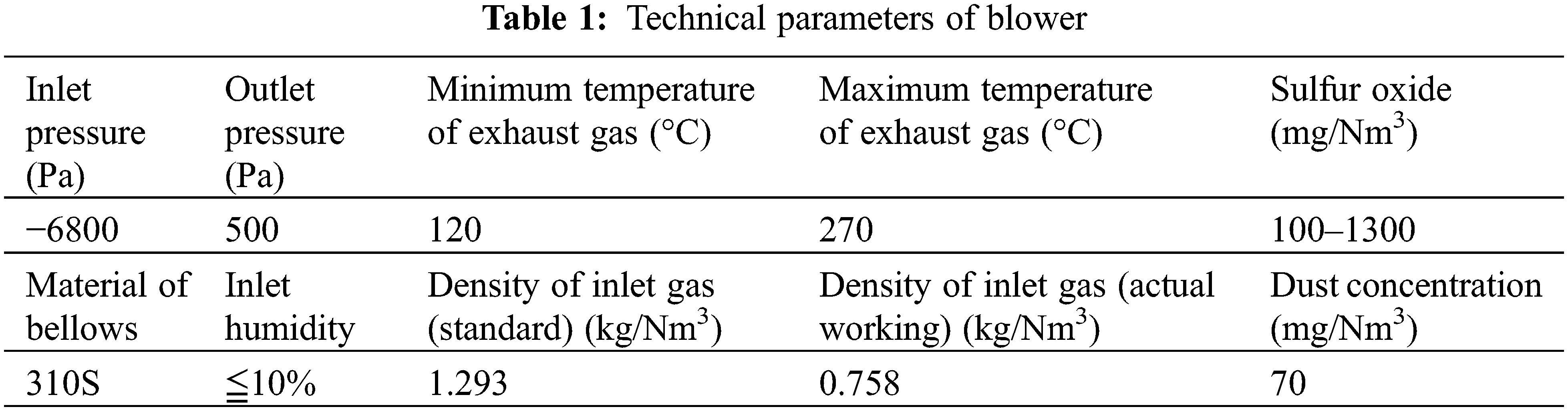
Selected parameters of the SO2 content at the inlet of waste gas 578 mg/Nm3, the humidity 6.5%, the inlet temperature 140°C, and the material of bellows 310S stainless steel, the corrosion of bellows was simulated based on SO2 corrosion model.
In Fig. 1, when the composition of SO2 changed from 0.02% to 0.17% at 140°C, the simulated corrosion rate changed from 8.89 μm/cm2•d to 41.65 μm/cm2•d, the increase of SO2 gas composition had a great influence on the corrosion rate of bellows.
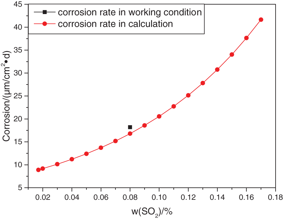
Figure 1: Corrosion of stainless steel under different content of SO2 at 140°C
In the field working condition of SO2 gas 578 mg/Nm3 (accounting composition about 0.0817%), the actual maximum corrosion rate of bellows after conversion is 18.2 μm/cm2•d. Location is at the lower trough of the bellows as shown in Fig. 2. The deviation between the calculated value and the actual corrosion rate is about 8%.
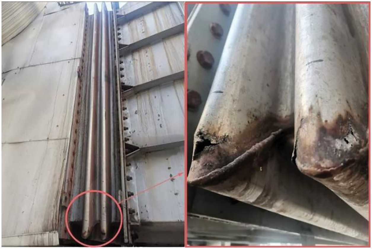
Figure 2: Maximum corrosion position of bellows for furnace blower
The simulated corrosion rate increased from 8.66 μm/cm2•d to 47.46 μm/cm2•d, in the temperature range from 120°C to 240°C in Fig. 3. The SO2 gas composition range from 0.02% to 0.17%. The maximum corrosion rate occurs when the SO2 gas component is 0.17%, and the working condition temperature is 240°C. The increase of SO2 gas composition had a greater effect on the corrosion rate of the bellows than that of temperature.
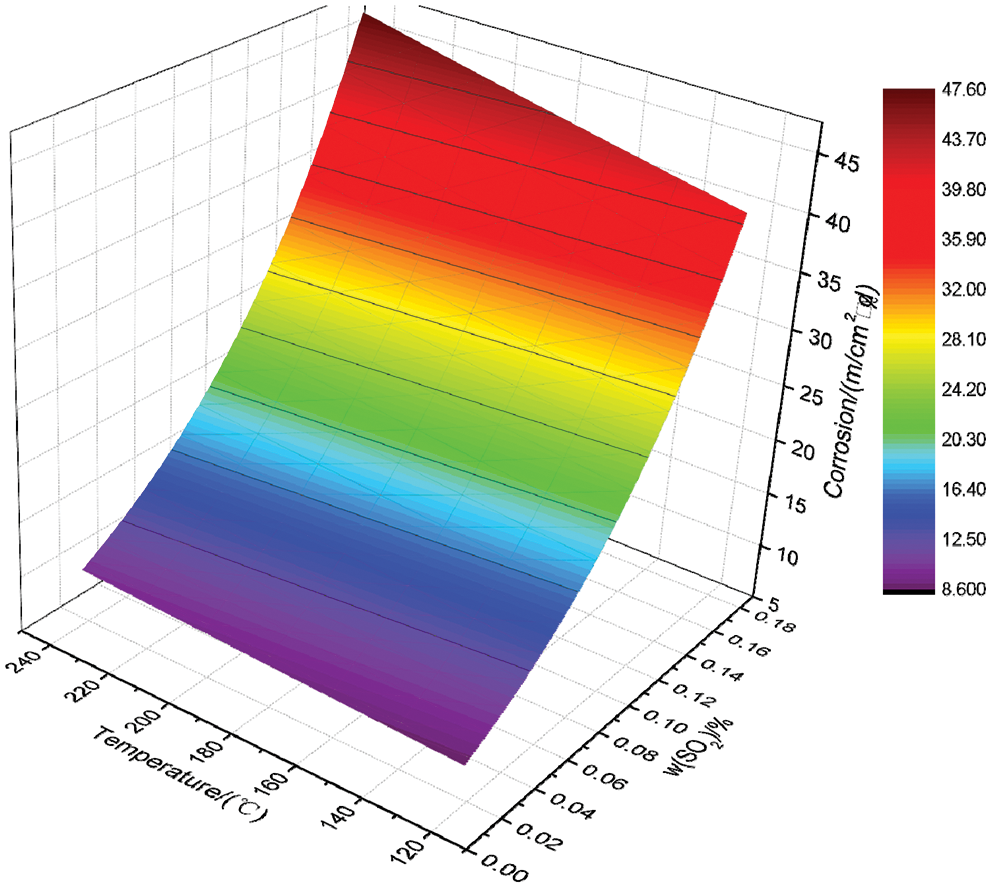
Figure 3: Corrosion of stainless steel under different content of SO2 at different temperatures
The bellows model described in Fig. 4 selected from the furnace blower was used to exhaust the flue gas in the drying and preheating sections. The diameter of the bellows is about 2 m, and the in-service inner draft tube of the bellows is an ordinary cylinder shape welded to one side of the cylinder. There is no corrosion-resistant filling material in the bellows. Under the gas monitoring in the pipeline, the average flow rate is 6 m/s, the SO2 content is 578 mg/Nm3, the humidity is 6.5%, and the monitoring temperature is 140°C. The material of the bellows and the inner draft tube is 310S.
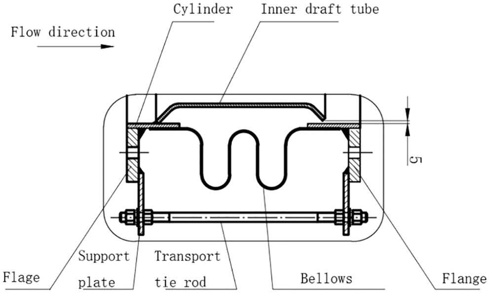
Figure 4: Schematic diagram of bellows
The bellows model was established on the severely corroded position at the lower part, and the grid division was shown in Fig. 5.
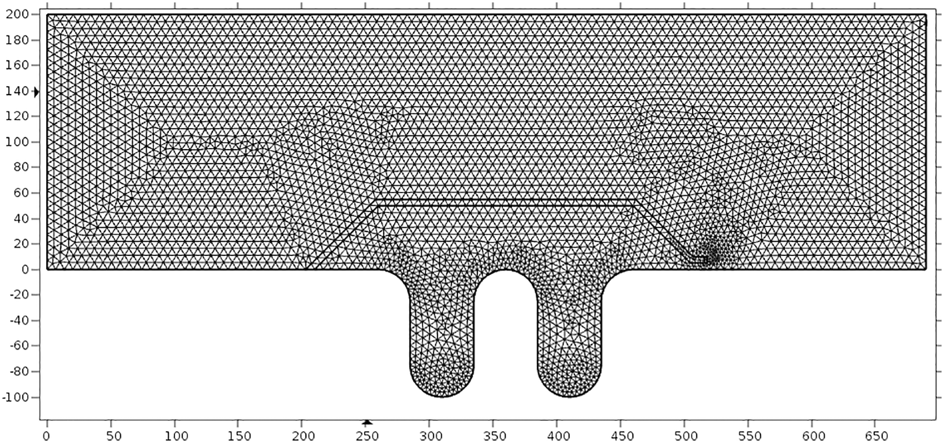
Figure 5: Meshing model of bellows flow field area
Gas-phase transport was assumed to be a quasi-continuous process to solve the transient response of structures. The inner part of the bellows was set as the fluid area, and the bellows and inner draft tube were set as the solid area. The left flow field calculation domain was set as velocity inlet condition (6 m/s), and the right was set as pressure outlet condition; the right side of the pipe was fixed as the solid boundary. The nonslip wall condition was adopted on the wall in contact with the fluid, and the staggering iterative method was used to solve it. Gas velocity and von Mises stress distribution were shown in Fig. 6.
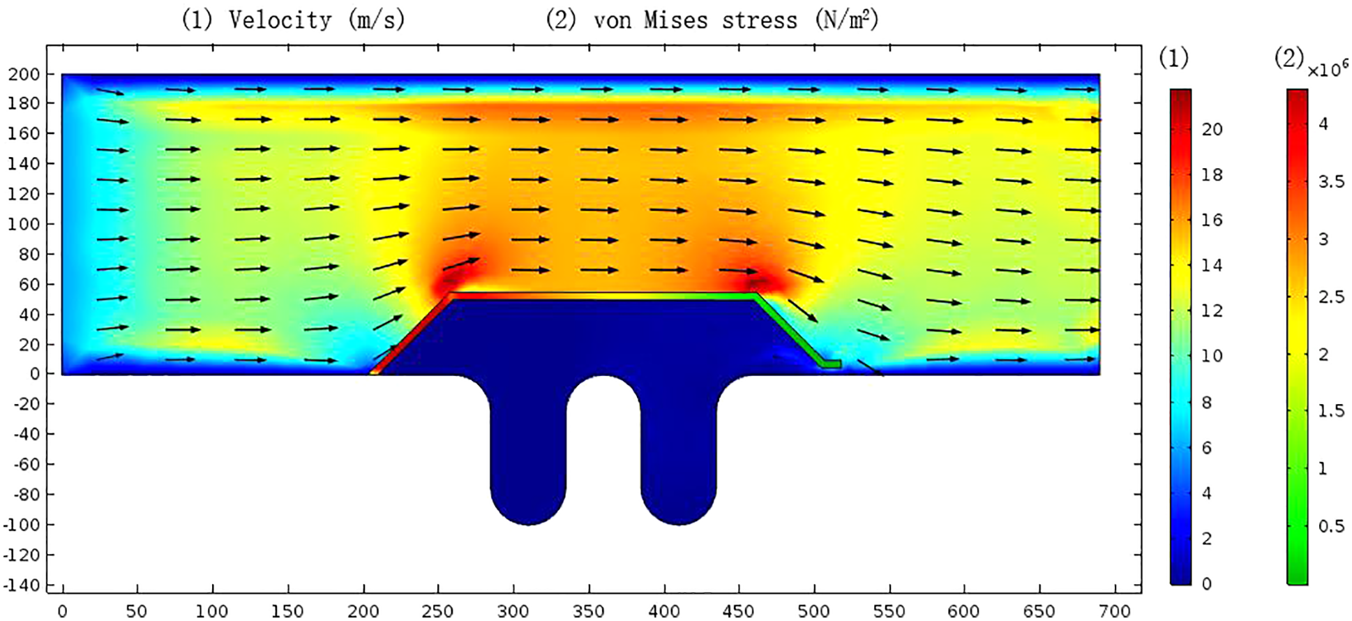
Figure 6: Gas velocity distribution in bellows (m/s) and von Mises stress distribution in the inner draft tube (N/m2)
The average flow rate of gas in the pipeline was maintained at about 6 m/s (Fig. 6). In the inlet area of the inner draft tube, the flow rate increased up to about 16 m/s due to the reduction of the flow channel; Since the inner draft tube and the bellows reserved a radial clearance of 5 mm (Fig. 4) for axial compensation of the bellows, the exhaust gas entered from the radial gap and resided between the inner draft tube and the bellows. The gas flow rate in the residential space was low, forming a stable semi-closed internal corrosion environment in which exhaust gas can be exchanged by radial clearance, especially at the lower trough of the bellows; it was easy to retain the water phase in the exhaust gas and increase the corrosion rate. The largest stress of the inner draft tube was at the upstream surface, and the von Mises stress reached 4 × 10⁶ N/m2.
As shown in Fig. 7, the pressure in the bellows was maintained at about 15 kPa due to the suction of the blower. In the semi-enclosed area between the inner draft tube and the bellows, the pressure was stable at about 3 kPa. The flow field had a small range of turbulence in the outlet area of the inner draft tube due to the narrow flow channel at the radial gap, and the pressure was slightly higher than the average value in the semi-closed area. The pressure was stable at the position with severe corrosion at the lower trough of the bellows (Fig. 2).
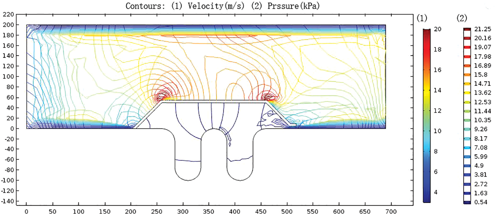
Figure 7: Contour map of gas velocity distribution and pressure distribution in bellows
3.3 Optimize the Structure of the Inner Draft Tube
According to the analysis of the corrosion and the flow field of the bellows, an optimized inner draft tube was proposed to improve the actual service life of the corrugated compensator.
As shown in Fig. 8, corrosion-resistant honeycomb buffer rings made of polyurethane were added inside bellows. The structure of the inner draft tube was optimized as a split streamline type, which converts the circulating lift force of the exhaust gas into the compression force of the corrosion-resistant honeycomb buffer ring by press plate. The split streamline draft tube was composed of 9 arc tiles, and the structure of the multi-tile combination was convenient for installation and fixation inside the bellows. The center angle of each arc tile was 30°, and each tile was evenly distributed in the cylinder in a circumferential direction with an interval of 10°. Each arc tile contained 2 × 3 press plates.
Figure 8: Corrugated compensator with the optimized structure of inner draft tube
As shown in Fig. 9, in the inlet area of the optimized split streamline draft tube, the gas velocity did not increase significantly, and the average velocity was about 5 m/s; the maximum von Mises stress of the split streamline draft tube was about 5 × 10⁴ Pa appeared at the joint of the draft tube and the press plate; the pressure plate was uniformly stressed, and the von Mises stress was about 1 × 10⁴ Pa.
Figure 9: Distribution of gas velocity distribution and von Mises stress in bellows after structural optimization of split streamline draft tube
As shown in Fig. 10, the maximum radial force generated in exhaust gas transportation can be obtained in the split streamline draft tube. The exhaust gas flow rate with an average speed of 6 m/s generated about 240 N radial thrust on each piece of arc tile. Therefore, the buffer rings were fixed radially through 54 pressing plates at the lower trough of the bellows. Each press plate provided a radial force of 60 N to tightly compact the buffer ring and bellows, to eliminate the semi-closed internal corrosion environment, and protect the bellows’ key corrosion position.
Figure 10: Distribution of von Mises stress of split streamline draft tube and press plate
Based on the analysis of the corrosion and FSI of the bellows in the blast furnace blower, the conclusions are as follows:
1. In the simulation of the corrosion, the simulated corrosion rate increased from 8.66 μm/cm2•d to 47.46 μm/cm2•d, in the temperature range from 120°C to 240°C and the SO2 gas composition range from 0.02% to 0.17%. The increase of SO2 gas composition had a greater effect on the corrosion rate of the bellows than that of temperature.
2. In the simulation of the FSI, a stable semi-closed internal corrosion environment was formed by the clearance between the inner draft tube and the bellows. Where the flow rate was low, and the water phase in the exhaust gas was easy to retain, increased the corrosion rate. The maximum corrosion position was well compared with the actual corrosion position on site.
Based on the simulation of the corrosion and the flow field of bellows, an optimized inner draft tube was proposed to improve the actual service life of the corrugated compensator. Corrosion-resistant honeycomb buffer rings made of polyurethane were added inside bellows. The structure of the inner draft tube was optimized as a split streamline type, which converts the circulating lift force of the exhaust gas into the compression force of the corrosion-resistant honeycomb buffer ring by press plate. The close compaction between the buffer rings and the bellows can effectively protect the key corrosion position of the original bellows. It can effectively eliminate the bellows’ vibration, alleviate the bellows’ corrosion and prolong the bellows’ service life. The research results can lay a theoretical foundation for the future’s popularization and application of bellows corrosion inhibition.
Funding Statement: The paper was funded by Science and Technology Project of Hebei Education Department (Project No. QN2022198).
Conflicts of Interest: The authors declare that they have no conflicts of interest to report regarding the present study.
References
1. The State Administration for Market Regulation (GB/T 12777-2019). General specification of metallic bellows expansion joints. Beijing, China: China Standards Press. [Google Scholar]
2. Liu, S. (2020). Failure cause and reliability of bellows compensator. Scientific and Technological Innovation, 13, 173–175. [Google Scholar]
3. Qin, Z. Q., Zhang, H. B., Xu, J. L., Zeng, C., Zheng, H. S. (2017). Analysis and treatment on the corrosion cracking of bellows compensator in Hot blast stove of No. 5 BF. Liugang Technology, 3. [Google Scholar]
4. Swift, S. C., Manning, F. C., Thompson, R. E. (1986). Sulfur bearing capacity of hydrogen sulfide gas. Society of Petroleum Engineers Journal, 4(16), 57–64. [Google Scholar]
5. Chen, J., Nie, L. L., Miao, J., Bai, Z. Q., Yan, W. (2013). Effect of temperature on elemental sulfur corrosion behavior of X65 steel. Journal of Xi’an University of Technology, 33(4), 309–312. [Google Scholar]
6. Liu, H. F. (2017). Effects of SO2 and O2 on corrosion of X65 steel in supercritical CO2 transport pipeline (Master Thesis). University of China University of Petroleum, China. [Google Scholar]
7. Ding, Y. S. (2016). A study on the mechanism and influencing factors of elemental sulfur corrosion (Master Thesis). University of Xi’an Shiyou University, China. [Google Scholar]
8. Xu, M., Zhang, Q., Yang, X., Wang, Z., Liu, J. et al. (2016). Impact of surface roughness and humidity on X70 steel corrosion in supercritical CO2, mixture with SO2, H2O, and O2. The Journal of Supercritical Fluids, 107, 286–297. DOI 10.1016/j.supflu.2015.09.017. [Google Scholar] [CrossRef]
9. Liu, Z. D., Lu, M. D., Xiao, X. L. (2012). Elemental sulfur corrsoion mechanism and evaluation methods for high sour gas fields. Chemical Engineering of Oil & Gas, 41(5), 495–498. [Google Scholar]
10. Hua, Y., Barker, R., Neville, A. (2015). The influence of SO2 on the tolerable water content to avoid pipeline corrosion during the transportation of supercritical CO2. International Journal of Greenhouse Gas Control, 37, 412–423. DOI 10.1016/j.ijggc.2015.03.031. [Google Scholar] [CrossRef]
11. Ayello, F., Evans, K., Thodla, R., Sridhar, N. (2010). Effect of impurities on corrosion of steel in supercritical CO2. In: CORROSION 2010. San Antonio, Texas. [Google Scholar]
12. Xiang, Y., Wang, Z., Xu, M., Li, Z., Ni, W. (2013). A mechanistic model for pipeline steel corrosion in supercritical CO2-SO2-O2-H2O environments. The Journal of Supercritical Fluids, 82(10), 1–12. DOI 10.1016/j.supflu.2013.05.016. [Google Scholar] [CrossRef]
13. Matsuiwa. (2004). Low alloy corrosion resistant steel, development and research. Beijing, China: Metallurgical Industry Press (Translated by Yu-kang Jin). [Google Scholar]
14. Fan, Z., Li, H. C., Liu, J. Y., Ouyang, X., Lu, L. (2013). The elemental sulfur deposition and its corrosion in high sulfur gas fields. Natural Gas Industry, 33(9), 102–109. [Google Scholar]
15. Andrianantenaina, M. H., Ratovonarivo, N., Zeghmati, B. (2022). Modeling the unsteady flow of a newtonian fluid originating from the hole of an open cylindrical reservoir. Fluid Dynamics & Materials Processing, 18(6), 1737–1748. DOI 10.32604/fdmp.2022.022047. [Google Scholar] [CrossRef]
16. Widjaja, G., Al-Thamir, M., Mehran, F., Yapanto, L. M., Fardeeva, I. N. et al. (2022). Optimizing fluid flow cooling in gas transmission systems. Fluid Dynamics & Materials Processing, 18(4), 1099–1109. DOI 10.32604/fdmp.2022.019489. [Google Scholar] [CrossRef]
17. Du, X. X., Liu, M. Y., Sun, Y. H. (2022). Optimization of the internal circulating fluidized Bed using computational fluid dynamics technology. Fluid Dynamics & Materials Processing, 18(2), 303–312. DOI 10.32604/fdmp.2022.016242. [Google Scholar] [CrossRef]
Cite This Article
 Copyright © 2023 The Author(s). Published by Tech Science Press.
This work is licensed under a Creative Commons Attribution 4.0 International License , which permits unrestricted use, distribution, and reproduction in any medium, provided the original work is properly cited.
 Downloads
 Citation Tools