
 Submit a Paper
 Propose a Special lssue
 Open Access
ARTICLE

A Model for the Determination of Semi-Circular Spot Corrosion Damage and Residual Strength in Oil Pipes
1 Research Institute of Oil and Gas Engineering Tarim Oilfield Company, PetroChina, Korla, 841000, China
2 CNPC Research Institute of Safety and Environment Technology, Beijing, 102206, China
* Corresponding Author: Bo Zhang. Email:
Fluid Dynamics & Materials Processing 2023, 19(6), 1709-1720. https://doi.org/10.32604/fdmp.2023.025513
Received 18 July 2022; Accepted 25 October 2022; Issue published 30 January 2023
 View Full Text
 Download PDF
Abstract
Pitting corrosion often occurs due to the presence of various corrosive substances, such as CO2 and H2S, in the pipe service environment. As a result of this process, the residual strength of oil pipes is reduced and this can compromise the integrity of the entire pipe string. In the present work, a model is introduced on the basis of the API579 standard to determine the so-called stress concentration coefficient. The model accounts for pitting corrosion shapes such as shallow semi-circles, semi-circles, and deep semi-circles. The relationship between the corrosion pit depth and opening diameter and the residual strength of the oil casing is obtained. The results show that the influence of the pit opening diameter on the stress concentration coefficient is smaller than that of the pit depth. For a constant pit opening diameter, the coefficient increases gradually with increasing the pit depth. The compressive strength and internal pressure strength of the carbon steel oil casing decrease accordingly. When the depth of the corrosion pit is relatively small, the growth of the coefficient is slower; when the depth of the corrosion pit increases to a certain value, the increase in stress concentration coefficient becomes obvious.Keywords
Nomenclature
| a | Radius of circular pit, mm |
| b | The radius of the outer boundary of the action area of stress concentration, mm |
| C | The correction coefficient of transforming finite plate problem into infinite plate problem, dimensionless |
| d | The opening diameter of the circular corrosion pit, mm |
| D | Outer diameter of carbon steel oil sleeve, mm |
| h | Depth of the corrosion pit, mm |
| K1, K2 | Intermediate parameters of the derivation process |
| Ktg | The stress concentration coefficient at the edge of the corrosion pit, dimensionless |
| m, n, K | are intermediate parameters in the derivation process |
| Pb | Internal pressure strength of carbon steel oil casing, kPa |
| | The internal pressure strength of carbon steel oil casing, kPa |
| r | Distance to the center of the semi-circular pit, mm |
| t | Thickness of carbon steel oil casing, mm |
| v | Poisson’s ratio, dimensionless, is generally 0.31 for steel |
| w, u | Intermediate parameters in the derivation process |
| σ | is tensile stress, MPa |
| σy | The minimum yield strength of the pipe body, kPa |
| σz | is Axial stress, MPa |
| ω, ψ, θ, β, γ | Angle used in the derivation of stress concentration coefficient, rad |
With the development of industrial technology, conventional onshore oil and gas fields can no longer meet the energy demand, and exploration and development are gradually growing in harsh environments such as deep formation [1,2], ocean [3,4], and polar regions [5]. Technological challenges also follow, one of which is the shortening of tubing life caused by tubing corrosion. In the production process, the casing is exposed to high temperature and high pressure for a long time, and it is in contact with the formation fluid containing corrosive substances such as CO2 or H2S, which greatly accelerates the corrosion of pipe and leads to the frequent failure of the casing, bringing huge economic losses and security concerns. Therefore, it is of great significance to analyze residual corrosion strength of oil pipes to guide safety in production. Casing residual strength evaluation results from the strength to consider whether the casing to meet the current pressure capacity, whether the need to replace the pipeline in service, to maximize the safety of the pipeline. There are three common corrosion types in oil pipe, local corrosion, uniform corrosion, and pitting corrosion. Corrosion type and form have a very important influence on the residual strength of oil and gas pipes [6,7]. Pitting corrosion has a high local penetration rate, which is actually a kind of local corrosion with hidden appearance but great damage. Although the metal weight lost due to pitting corrosion is very small, it will lead to perforation of corroded pipes with great harm if it develops continuously [8,9]. Among all pitting corrosion shapes, semicircle is the most common. Therefore, it is very important to evaluate residual strength of semi-circular corroded pipe.
Pitting corrosion defects are volumetric corrosion defects, and API579, DNVRP-F101 and ASMEB31G are usually used to evaluate residual strength of pipe with volumetric defects. These standards are clearly defined, but there are some limitations in describing precise failure pressure, and they cannot take account of the nonlinearity of materials, such as elastic-plastic effect of pipelines. Moreover, most of the evaluation methods such as API579 take the pitting corrosion of cube shape with regular length, width, and depth as the research object. Mondalb et al. [10] carried out relevant studies on the failure mechanism of regular corroded pipe under internal pressure, and gave the calculation method of ultimate internal pressure load of corroded pipe. Sedmak et al. [11] studied the casing pipes integrity after 70,000 h of wellbore service. The finite element analysis was applied in the analysis of the damaged pipe subjected to internal pressure and the stress state was simulated to establish the criteria for the maximum pressure that a damaged pipe can withstand. Nazaria et al. [12] presented a result about the ultimate strength of locally corroded tubular under axial compressive loads, which indicated that the corrosion geometry could impact the tubular behaviors under compressive loads. Martin et al. [13] used an electromagnetic corrosion inspection tool to accurately assess pipe corrosion. The results showed that the tool can accurate assess the fourth and fifth pipes and provided useful information for the decision-making for mature well operations. Liang et al. [14] fully considered the dual effects of pitting corrosion and fatigue damage and proposed a failure analysis model based on a dynamic Bayesian network. Abdallah et al. [15] reviewed the casing corrosion measurement and indicated that casing corrosion could shorten the wellbore service life. Gallego et al. [16] found that pitting corrosion and cracking led to tubing failure in water injection wells through microscopy observations, chemical analyses and computational fluid dynamic simulations. Laumb et al. [17] provided proofs for the small corrosion pits in the casing through two case wells and verified that the corrosion casing was one of the reasons for wellbore leakage.
Although the above researchers put forward some residual strength criteria for casing with volume defects, these criteria cannot guide the calculation of residual strength of semi-circular irregular pitting shape. Therefore, it is necessary to evaluate the residual strength of oil casing with semi-circular irregular pitting defects.
2 Stress Concentration Coefficient Due to Point Corrosion
The corrosion pit on the inner wall of the carbon steel oil casing is regarded as a two-dimensional circular corrosion pit to solve its stress concentration coefficient. For the stress concentration at the edge of the circular hole on the general infinite plate, elastic mechanics can be used to accurately solve the stress concentration [18]. The derivation of the stress concentration coefficient of the corrosion pit in carbon steel oil casing is based on the problem that there is a kind of circular corrosion pit on a finite cylinder. Let b→∞, it can be considered as the case of an infinite plate. According to elasticity, the axial stress distribution on both sides of the hole is [3]:
When r = a, the axial stress is the largest, and its value is:
2.1 Shallow Semi-Circular Corrosion Pit
The quasi-circular corrosion pit whose corrosion depth h is less than the opening radius (h < d/2) is defined as a shallow semi-circular corrosion pit. The relationship between the surface radius a, opening diameter d, and depth h of shallow semi-circular corrosion pits can be expressed as follows:
Shallow circular corrosion pits can be analyzed simply as a plate problem, assuming that the stress σ is distributed along the axial direction of the carbon steel oil casing. The radius of the outer boundary can be expressed as follows:
The resultant force of σy distributed along the y direction of the hole should be equal to the resultant force of far-field stress σ in the shadow. After multiplying by a stress concentration factor C, the infinite plate problem can be transformed into a finite plate hole problem, and the equation is [5]:
The solution is as expressed by Eq. (6),
Therefore, the stress concentration coefficient at the edge of the shallow semi-circular corrosion pit is:
The m, n, K are intermediate parameters in the derivation process. Among them,
2.2 Semi-Circular Corrosion Pit
The quasi-circular corrosion pit whose corrosion depth h is equal to the corrosion opening radius (h = d/2) is defined as a semicircular corrosion pit. For semi-circular corrosion pits,
The balance equation of force in the y-axis direction is:
The solution is as follows:
Therefore, the stress concentration coefficient at the edge of the semi-circular corrosion pit is:
Among them,
2.3 Deep Semi-Circular Corrosion Pit
The quasi-circular corrosion pit whose corrosion depth h is greater than the corrosion opening radius (h > d/2) is defined as a deep semi-circular corrosion pit. In the figure, a = (d2 + 4h2)/8h, b = a − h + t. The balance equation of force in the y-axis direction is:
The solution is as follows:
Therefore, the stress concentration coefficient at the edge of a deep semi-circular corrosion pit is:
Among them,
3 Residual Strength of Carbon Steel Oil Casing Considering Pitting Corrosion
The influence of corrosion on the strength of carbon steel oil bushing is mainly because of the stress concentration at the edge of the corrosion pit, which changes the stress distribution of carbon steel oil bushing at the edge of the corrosion pit, and thus changes the strength of carbon steel oil bushing. Influence of corrosion on strength of carbon steel oil bushing can be evaluated by the stress concentration coefficient. Choi et al. [18] studied the influence of stress concentration on the internal pressure of carbon steel oil casing and proposed a modified formula for internal pressure strength.
3.1 API Standard Carbon Steel Oil Sleeve Strength Calculation Formula
API carbon steel oil sleeve internal pressure strength formula is:
The API yield strength collapse formula of carbon steel oil sleeve is:
3.2 Internal Pressure Strength and Squeeze Strength of the Corroded Carbon Steel Oil Sleeve
Choi et al. [18] believed that the stress concentration coefficient could be used to directly modify the internal pressure strength of carbon steel oil casing. Assuming that the stress concentration coefficient at the hole edge of quasi-circular hole was Ktg, formula for the internal pressure strength of the corroded carbon steel oil casing was as follows:
The compressive strength of carbon steel oil casing can be modified by using the same method that considers the influence of stress concentration on the compressive strength of carbon steel oil casing [16].
The formula of compressive strength of corroded carbon steel oil sleeve is:
Steel grade TP140V carbon steel oil casing with Φ139.7 mm and wall thickness of 12.09 mm in KeS8-2 well was selected for corrosion analysis, and the opening diameter of circular corrosion pit on carbon steel oil casing was set as d = 6 mm. The calculation method of stress concentration coefficient was as follows: When the hole depth h is less than 5 mm, the corrosion of carbon steel oil casing is shallow semi-circular pit, which can be calculated by formula (7). When hole depth h is equal to 5 mm, the corrosion of carbon steel oil casing is semi-circular pit, which can be calculated by formula (10). When the hole depth h is more than 5 mm, the corrosion of the carbon steel oil casing is deep semi-circular pit, which can be calculated by formula (13).
By calculating the distribution of stress concentration coefficient Ktg with different hole depth h, the corresponding strength reduction of carbon steel oil casing with different hole depths can be obtained. The stress concentration coefficient distribution corresponding to different hole depths is calculated as shown in Fig. 1. As can be seen from the figure, when the opening diameter d of the corrosion pit is constant, the stress concentration coefficient at the edge of the corrosion pit increases gradually with the increase of the corrosion pit depth. When the depth of the corrosion pit is small, the increase of the stress concentration coefficient is slower, when the depth of the corrosion pit increases to a certain value, the increase in stress concentration coefficient becomes obvious.
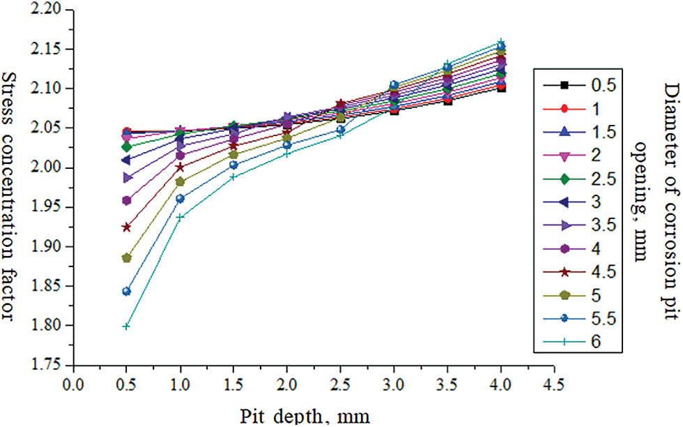
Figure 1: Variation of stress concentration coefficient at corrosion pit edge with corrosion pit depth
As the diameter of the corrosion pit opening increases, the variation trend of the stress concentration coefficient at the edge of the corrosion pit is shown in Fig. 2. It can be seen from the figure that the influence of corrosion pit opening diameter on stress concentration coefficient is not as obvious as the influence of corrosion pit depth on stress concentration coefficient, and stress concentration coefficient is mainly affected by corrosion pit depth. When the pit opening diameter is smaller than the thickness of the carbon steel oil casing wall, the stress concentration coefficient increases with the increase of the pit opening diameter. When pit opening diameter is larger than the thickness of the carbon steel oil casing wall, the stress concentration coefficient decreases with the increase of pit opening diameter.
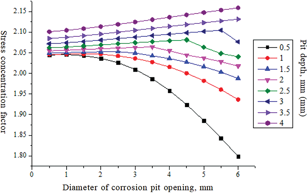
Figure 2: Influence of corrosion pit opening diameter on stress concentration coefficient
The influence of corrosion pit depth on compressive strength and internal pressure strength of carbon steel oil sleeve is analyzed below. The influence of corrosion pit depth on the compressive strength of the carbon steel oil sleeve is shown in Fig. 3. The influence of the corrosion pit on the internal pressure strength of carbon steel oil sleeve is shown in Fig. 4. It can be seen from the figure that the depth of the corrosion pit affects the compressive strength and internal pressure strength of the carbon steel oil sleeve. With the increase of the depth of the corrosion pit, the stress concentration coefficient at the edge of the corrosion pit increases, and the compressive strength and internal pressure strength of the carbon steel oil sleeve will decrease.
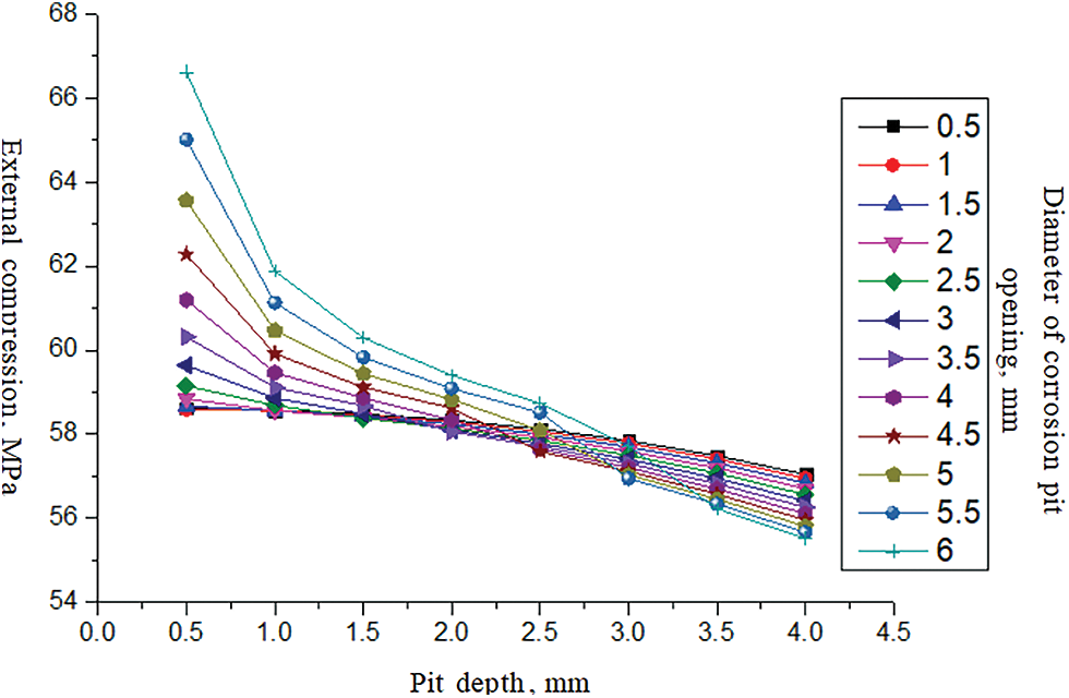
Figure 3: Influence of corrosion pit depth on the compressive strength of carbon steel oil casing
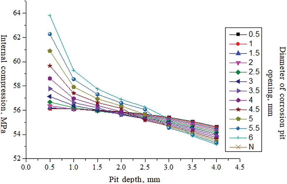
Figure 4: Influence of corrosion pit depth on internal pressure strength of carbon steel oil casing
A steel grade 13Crs-110 pipe with a diameter of Φ88.9 mm and a wall thickness of 7.34 mm was selected for corrosion analysis. Assuming that the opening diameter of circular corrosion pit on carbon steel oil casing was d = 6 mm, the distribution of stress concentration coefficient Ktg with different hole depth h was calculated, and the corresponding strength reduction of pipe with different hole depth h was obtained.
The stress concentration coefficient distribution corresponding to different hole depths is calculated as shown in Fig. 5. As can be seen from the figure, when the opening diameter d of the corrosion pit is constant, the stress concentration coefficient at the edge of the corrosion pit increases gradually with the increase of the corrosion pit depth. When the depth of the corrosion pit is small, the increase of stress concentration coefficient is slower. When the depth of the corrosion pit increases to a certain value, the increase in stress concentration coefficient becomes obvious.
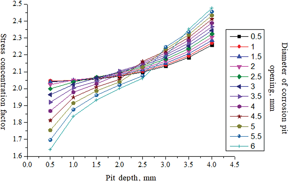
Figure 5: Variation of stress concentration coefficient at the edge of corrosion pit with the depth of corrosion pit
As the diameter of the corrosion pit opening increases, variation trend of the stress concentration coefficient at the edge of corrosion pit is shown in Fig. 6. It can be seen from the figure that the influence of corrosion pit opening diameter on the stress concentration coefficient is not as obvious as the influence of corrosion pit depth on the stress concentration coefficient, and the stress concentration coefficient is mainly affected by corrosion pit depth. When the pit opening diameter is smaller than the pipe wall thickness, the stress concentration coefficient increases with the increase of the pit opening diameter; when the pit opening diameter is larger than the pipe wall thickness, the stress concentration coefficient decreases with the increase of pit opening diameter.
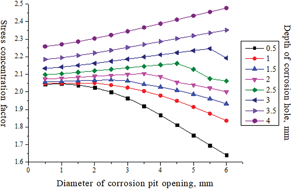
Figure 6: Influence of corrosion pit opening diameter on stress concentration coefficient
The influence of corrosion pit depth on compressive strength and internal pressure strength of oil pipe is analyzed below. The influence of corrosion pit depth on the compressive strength of the carbon steel oil sleeve is shown in Fig. 7. The influence of the corrosion pit on the internal pressure strength of the pipe is shown in Fig. 8. It can be seen from the figure that the depth of the corrosion pit affects the compressive strength and internal pressure strength of the pipe. As the depth of the corrosion pit increases, the stress concentration coefficient at the edge of the corrosion pit increases, and both the compressive strength and internal pressure strength of the pipe decrease.
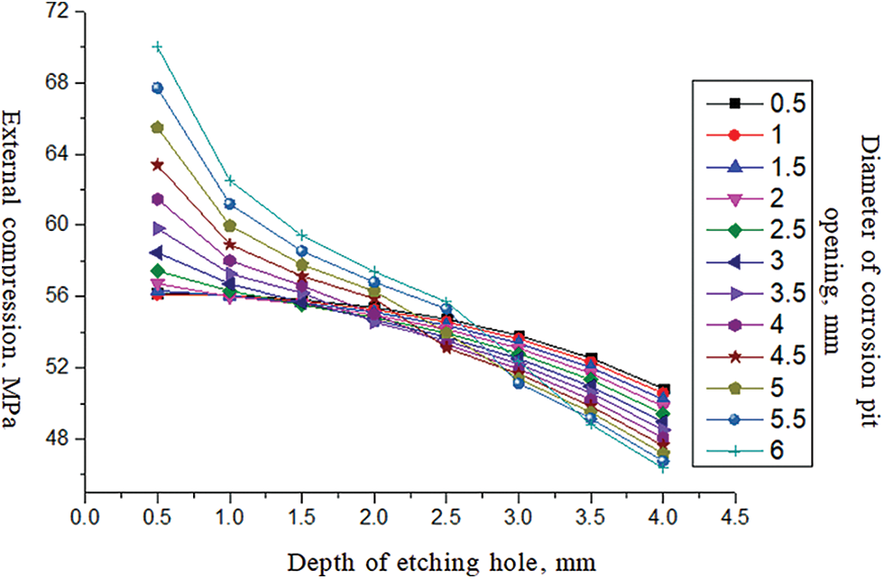
Figure 7: Influence of corrosion pit depth on pipe compressive strength
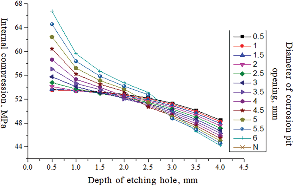
Figure 8: Influence of corrosion pit depth on internal pressure strength of the pipe
(1) When the opening diameter of the corrosion pit is constant, the stress concentration factor at the edge of the corrosion pit increases with the increase of the depth of the corrosion pit, and the collapse strength and internal pressure strength of the carbon steel oil casing will decrease. When the depth of the corrosion pit is small, the increase of the stress concentration factor is slower; when the depth of the corrosion pit increases to a certain value, the increase of stress concentration factor becomes obvious.
(2) When the opening diameter of the corrosion pit is constant, the stress concentration coefficient of the corrosion pit edge increases gradually with the increase of corrosion pit depth. When the depth of the corrosion pit is small, the increase of the stress concentration coefficient is slower. When the depth of the corrosion pit increases to a certain value, the increase of stress concentration coefficient becomes obvious.
(3) Compared with the corrosion pit opening diameter, the effect of corrosion pit depth on stress concentration factor is more obvious; when the corrosion pit opening diameter is less than the oil pipe wall thickness, the stress concentration factor increases with the increase of the corrosion pit opening diameter. When the diameter of the corrosion pit opening is greater than the thickness of the oil pipe wall, the stress concentration factor will gradually decrease as the diameter of the corrosion pit opening increases.
Funding Statement: The project is supported by CNPC Forward-Looking Basic Strategic Technology Research Projects (Nos. 2021DJ6504, 2021DJ6501, 2021DJ6502 & 2021DJ0806) received by Bo Zhang. The authors also thank the PetroChina Tarim Field Company for providing the support and the field data.
Conflicts of Interest: The authors declare that they have no conflicts of interest to report regarding the present study.
References
1. Worden, R. H., Smalley, P. C. (1996). H2S-producing reactions in deep carbonate gas reservoirs: Khuff formation, Abu Dhabi. Chemical Geology, 133(1–4), 157–171. DOI 10.1016/S0009-2541(96)00074-5. [Google Scholar] [CrossRef]
2. Zhang, B., Lu, N., Guo, Y., Wang, Q., Cai, M. et al. (2022). Modeling and analysis of sustained annular pressure and gas accumulation caused by pipe integrity failure in the production process of deep natural gas wells. Journal of Energy Resources Technology, 144(6), 063005. DOI 10.1115/1.4051944. [Google Scholar] [CrossRef]
3. Camilli, R., di Iorio, D., Bowen, A., Reddy, C. M., Techet, A. H. et al. (2012). Acoustic measurement of the deepwater horizon macondo well flow rate. Proceedings of the National Academy of Sciences, 109(50), 20235–20239. DOI 10.1073/pnas.1100385108. [Google Scholar] [CrossRef]
4. Zhang, B., Xu, Z., Lu, N., Liu, H., Liu, J. et al. (2021). Characteristics of sustained annular pressure and fluid distribution in high pressure and high temperature gas wells considering multiple leakage of tubing string. Journal of Petroleum Science and Engineering, 196, 108083. DOI 10.1016/j.petrol.2020.108083. [Google Scholar] [CrossRef]
5. Engelhardt, F. R. (1994). Limitations and innovations in the control of environmental impacts from petroleum industry activities in the Arctic. Marine Pollution Bulletin, 29(6–12), 334–341. DOI 10.1016/0025-326X(94)90650-5. [Google Scholar] [CrossRef]
6. Anwar, I., Chojnicki, K., Bettin, G., Taha, M. R., Stormont, J. C. (2019). Characterization of wellbore casing corrosion product as a permeable porous medium. Journal of Petroleum Science and Engineering, 180, 982–993. [Google Scholar]
7. Mahmoodian, M., Li, C. Q. (2017). Failure assessment and safe life prediction of corroded oil and gas pipelines. Journal of Petroleum Science and Engineering, 151, 434–438. DOI 10.1016/j.petrol.2016.12.029. [Google Scholar] [CrossRef]
8. Mohammed, A. I., Oyeneyin, B., Atchison, B., Njuguna, J. (2019). Casing structural integrity and failure modes in a range of well types–A review. Journal of Natural Gas Science and Engineering, 68, 102898. DOI 10.1016/j.jngse.2019.05.011. [Google Scholar] [CrossRef]
9. Meresht, E. S., Farahani, T. S., Neshati, J. (2011). Failure analysis of stress corrosion cracking occurred in a gas transmission steel pipeline. Engineering Failure Analysis, 18(3), 963–970. DOI 10.1016/j.engfailanal.2010.11.014. [Google Scholar] [CrossRef]
10. Mondalb, C., Dhar, A. S. (2015). Corrosion effects on the strength of steel pipes using FEA. International Conference on Offshore Mechanics and Arctic Engineering, OMAE2015-42003, V05AT04A022. Newfoundland, Canada. [Google Scholar]
11. Sedmak, A., Arsić, M., Šarkoćević, Ž., Medjo, B., Rakin, M. et al. (2020). Remaining strength of API J55 steel casing pipes damaged by corrosion. International Journal of Pressure Vessels and Piping, 188, 104230. DOI 10.1016/j.ijpvp.2020.104230. [Google Scholar] [CrossRef]
12. Nazaria, M., Khedmati, M. R., Khalaj, A. F. (2014). A numerical investigation into ultimate strength and buckling behavior of locally corroded steel tubular members. Latin American Journal of Solids and Structures, 11, 1063–1076. DOI 10.1590/S1679-78252014000600010. [Google Scholar] [CrossRef]
13. Martin, L. E., Fouda, A. E., Amineh, R. K., Capoglu, I., Donderici, B. et al. (2017). New high-definition frequency tool for tubing and multiple casing corrosion detection. Abu Dhabi International Petroleum Exhibition & Conference, Abu Dhabi, UAE. [Google Scholar]
14. Liang, Z., Xiao, Y., Zhang, J. (2018). Stress–strain analysis of a pipeline with inner and outer corrosion defects. Journal of Pressure Vessel Technology, 140(6), 64501. DOI 10.1115/1.4041434. [Google Scholar] [CrossRef]
15. Abdallah, D., Fahim, M., Al-Hendi, K., Al-Muhailan, M., Jawale, R. et al. (2013). Casing corrosion measurement to extend asset life. Oilfield Review, 22(3), 18–31. [Google Scholar]
16. Gallego, M., San Román, J., Bianchi, G. L., Otegui, J. L. (2021). Influence of fluid flow in microbiological corrosion failures in oil field injector well tubing. Engineering Failure Analysis, 128, 105603. DOI 10.1016/j.engfailanal.2021.105603. [Google Scholar] [CrossRef]
17. Laumb, J. D., Glazewski, K. A., Hamling, J. A., Azenkeng, A., Watson, T. L. (2016). Wellbore corrosion and failure assessment for CO2 EOR and storage: Two case studies in the weyburn field. International Journal of Greenhouse Gas Control, 54, 479–489. DOI 10.1016/j.ijggc.2016.08.031. [Google Scholar] [CrossRef]
18. Choi, K. H., Lee, C. S., Ryu, D. M., Koo, B. Y., Kim, M. H. et al. (2016). Comparison of computational and analytical methods for evaluation of failure pressure of subsea pipelines containing internal and external corrosions. Journal of Marine Science and Technology, 21(3), 369–384. DOI 10.1007/s00773-015-0359-5. [Google Scholar] [CrossRef]
Cite This Article
 Copyright © 2023 The Author(s). Published by Tech Science Press.
This work is licensed under a Creative Commons Attribution 4.0 International License , which permits unrestricted use, distribution, and reproduction in any medium, provided the original work is properly cited.
 Downloads
 Citation Tools