
 Submit a Paper
 Propose a Special lssue
 Open Access
ARTICLE

Mechanical Analysis of a Multi-Test String in High-Temperature and High-Pressure Deep Wells
Downhole Operation Branch of Sinopec Southwest Petroleum Engineering Corporation, Deyang, 618000, China
* Corresponding Author: Zubing Tang. Email:
Fluid Dynamics & Materials Processing 2023, 19(8), 2161-2170. https://doi.org/10.32604/fdmp.2023.026608
Received 15 September 2022; Accepted 24 November 2022; Issue published 04 April 2023
 View Full Text
 Download PDF
Abstract
The mechanical behavior of the test string in deep wells is generally relatively complex as a result of the high temperature and high pressure, severe dogleg and buckling effects, which in some circumstances can even lead to string failure. Traditional computational methods for the analysis of these behaviors are often inaccurate. For this reason, here a more accurate mechanical model of the test string is introduced by considering variables such as temperature, pressure, wellbore trajectory, and buckling, as well as combining them with the deformation and string constraint conditions brought in by changes in temperature and pressure during the tripping, setting, and test operations. The model is validated by applying it to a specific high-pressure gas well (located in Northeast Sichuan).Keywords
It is difficult to conduct test operations effectively and safely due to the ongoing development of deep wells with high temperatures and pressures, which create harsh downhole conditions. The geological conditions of high-temperature and high-pressure deep wells are complex (deep reservoir, high pressure, high temperature), and are accompanied by a complex wellbore structure. The test string routinely involves steps like tripping, setting, acid injection, production, etc. In a high-temperature and high-pressure environment, the load, deformation, and change in tension of the test string under each operation are particularly visible, which has a significant impact on the safety and reliability of the downhole test string. As a result, the mechanical model of the test string must be built in accordance with the technical characteristics of high temperature and high pressure deep horizontal wells to provide a theoretical foundation for the test string’s design.
There has been a lot of theoretical research and experimental analyses on the mechanical problems of downhole string. Johancsik et al. [1] first studied the string force in a three-dimensional wellbore trajectory, ignoring the string stiffness to establish a three-dimensional soft rod model. Through experiments, Sheppard et al. [2] discovered that the friction coefficient in the soft rod model is a comprehensive value that is affected by wellbore parameters and mud. Ho [3] devised a three-dimensional rigid rod model after initially taking the tubular string’s rigidity into account, although the model is challenging to solve. The influencing aspects and solving methods of the soft rod model and the rigid rod model were enhanced by lots of experts [4–7]. Lubinski [8] initially introduced the idea of helical buckling for the tubular string buckling problem, followed by an energy method study of the packer tubular string buckling behavior, from which the relationship between pitch and compression force was derived. The essential sinusoidal buckling load of inclined vertical wells was determined by Paslay et al. [9].
Wu [10] introduced the critical buckling load and the additional contact force caused by buckling into the overall stress model of the string and established the load model of the downhole string considering the buckling effect. According to the principle of sliding friction, Mitchell [11–12] established the load model of the string shaft with buckling and determined the buckling length of the string and the contact load with the wellbore wall. Li et al. [13] considered the influence of the string joint and centralizer, combined with the buckling of the drill string, and established a full string load model coupling the local and overall stress of the string. Lian et al. [14] developed a finite element model of tubular string buckling, investigated the buckling form and lateral displacement of tubular string under different boundary conditions under complex working conditions, and evaluated pipe string buckling relief schemes such as optimizing output, adding a centralizer, and designing expansion joint.
The mechanical behavior of downhole strings has been extensively studied by pioneers, but previous models of mechanical string testing did not subdivide the entire testing process. The boundary conditions of the entry, setting, and testing of the string are not linked, and the stress calculation of the test string under the test condition is not accurate. In this paper, factors such as temperature, pressure, wellbore trajectory, and buckling are comprehensively considered. Combined with the deformation and string constraint conditions caused by temperature and pressure changes in the working process of tripping, setting, and testing, the mechanical model of the muti-test string is established, which provides a theoretical guide for the design of the test strings in deep horizontal wells with high-temperature and high-pressure environments.
2 Three-Dimensional Mechanical Model of Downhole Test String
The establishment of a mechanical model of a test string needs to make the following assumptions:
The following assumptions should be made before establishing the mechanical model of the test string:
1. The curvature of the unit string element is constant, and the test string axis coincides with the borehole axis;
2. The wellbore trajectory data between two measured points is in the same spatial plane;
3. The bending deformation of the string is within the elastic range;
4. The edge of the string is in continuous contact with the casing.
The test string was separated into N unit segments from the bottom to the wellhead, and the unit segment j of the test string was selected as the research object to conduct force analysis. The three-dimensional force diagram of the unit segment was obtained, as shown in Fig. 1.
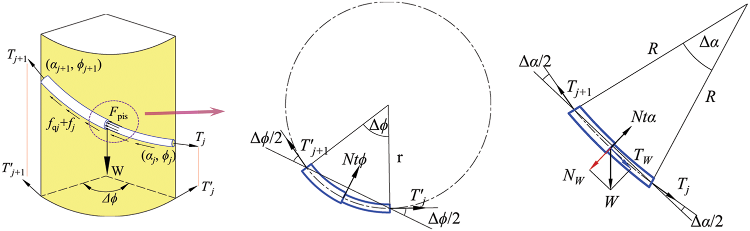
Figure 1: The stress diagram of the unit test string
According to the force of the unit segment string on the arc surface, the force of the unit test string is decomposed into the horizontal and vertical planes, and then synthesized and simplified [1]. The test mechanical model is established as follows:
where W is the weight per unit length of the test string, N/m; Tj+1 is the true axial force on the upper face of the unit segment test string, N; Tj is the true axial force on the lower face of the unit segment test string, N; ΔT is the axial force increment of the unit segment test string, N; αj+1, αj are the deviation angles of the upper end face and the lower end face of the unit test string, rad; ϕj+1, ϕj are the azimuth angles of the upper end face and the lower end face of the unit segment test string, rad; Δα is the increment of well inclination angle, rad; Δϕ is azimuth angle increment, rad; Nj is the lateral force of the unit segment test string, N; fj is the friction caused by the lateral force of the unit segment test string, N; μ is the friction coefficient between the string and the sleeve wall; Nq, fq are the buckling contact force and buckling friction between the string and the casing, N; L is the length of the unit segment test string, m.
When the effective axial compression force of the test string is greater than the critical buckling load (the critical load equation is shown in Table 1), that is, −Te < −Fsin or −Te < −Fhel, the test string will buckle and make contact with the wellbore or casing. Buckling increases the contact force between the string and the wellbore casing due to string weight or wellbore trajectory bending. The additional contact force Nq of unit-length buckling is [12]:
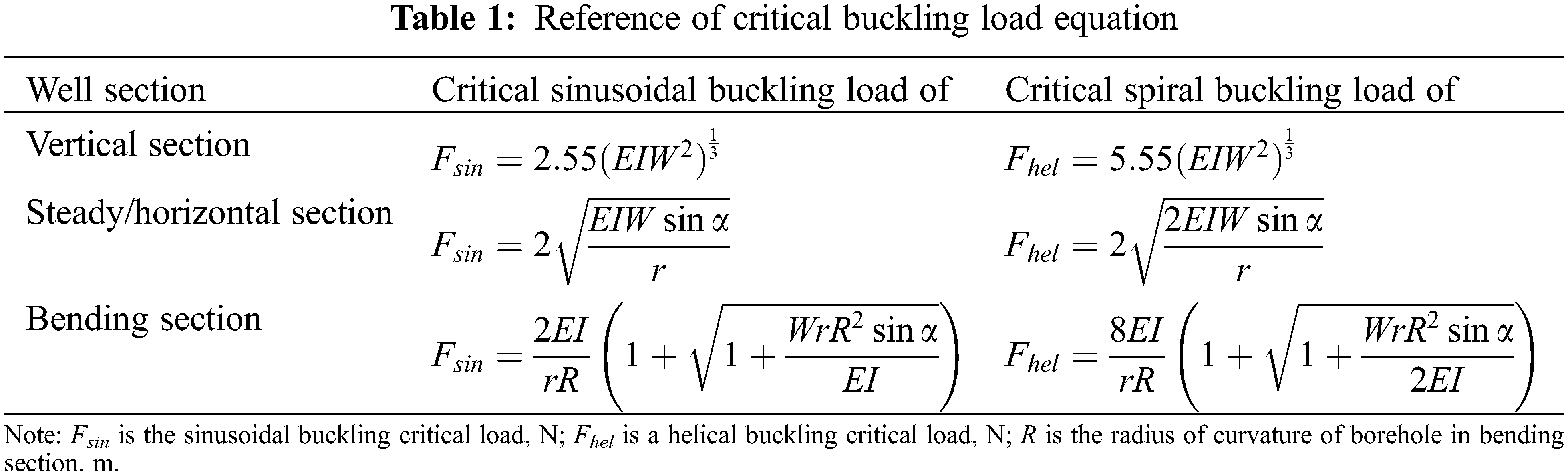
where Te is the effective axial force of the test string, N; r is the annulus space gap between the test string and the casing, m; I is the moment of inertia of the test string, m4; E is the elastic modulus of the test string, Pa.
The effective axial force Te can be expressed as [15]:
where Te and T are the effective axial force and the true axial force of the unit test string, N; Po and Pi are the external pressure and internal pressure of the unit segment test string, respectively, Pa; Ai and Ao are the inner area and outer area of the current string, respectively, m2.
There is a variable diameter in the multi-test string, and the piston force of the variable section of the string cannot be ignored. The equation for the calculation of the piston force at the bottom of the nth-sleeve test string is [16]:
where n is the series number of the test string (from bottom to top); Fpisn is the nth level test string bottom piston force, N; Ain is the area surrounded by the inner diameter of the nth-sleeve test string, m2; Aon is the area surrounded by the outer diameter of the nth-sleeve test string, m2; Pin is the internal pressure at the bottom of the nth-sleeve test string, Pa; Pon is the annulus fluid pressure at the bottom of the nth-sleeve test string, Pa;
In actual horizontal wells, the buckling configurations of different sections are different, and the reference equations of critical buckling loads for different sections [16] are given in Table 1.
3 Test String Deformation Model
During the operation of the test string, the internal pressure, external pressure, wellbore flow parameters, and wellbore temperature of the string change with the test conditions, resulting in different forms of deformation of the test string. Under the constraint of the packer and wellhead, the deformation is transformed into load [17]. The effective deformation is reflected in the following aspects.
After the packer is sealed, the temperature of the test string significantly changes along the depth of the well, and there is deformation of the axial thermal expansion effect. The equation for calculating the deformation caused by the temperature effect of the test string under certain working conditions is:
where ΔL1 is the axial deformation of the test string under the temperature effect, m; β is the string’s thermal expansion coefficient, °C−1; Δkj is the temperature change of test string unit j relative to before setting, °C; Lj is the length of the test string segment j, m; and N is the total number of the test string units.
Under different operating conditions of the test string, the fluid pressure inside and outside the pipe changes greatly, which will cause the radial expansion or contraction of the tubing and cause axial deformation. The equation for calculating the deformation caused by the ballooning effect of the test string under certain operating conditions is:
where ΔL2 is the axial deformation of the test string under the action of the ballooning effect, m; μ is the Poisson’s ratio of the test string; ΔPij is unit j to test the change of internal pressure of the test string relative to the pre-setting, Pa; ΔPoj is unit j to test the change of external pressure of the column relative to the pre-setting, Pa; roj is the outer radius of the test string in unit j, m; rij is the inner radius of the test string in unit j, m.
The test string is generally a multi--sleeve string. The change in fluid pressure inside and outside the string will act on the shoulder between the test tubes to form a piston force. The deformation of the test string under the piston effect is:
where ΔL2 is the axial deformation of the test string under the piston effect, m; M is the total sleeves of the test string; Lsn is the length of level n sleeve test string, m; Fpis(n−1) is the piston force at the bottom of the n−1th sleeve test string, N; ΔPin is the change value of internal pressure at the bottom of the nth sleeve test string, Pa; ΔPon is the change value of annulus fluid pressure at the bottom of the nth sleeve test string, Pa.
When the effective axial compression force of the test string reaches the critical buckling load, the string will buckle. The model for calculation of the critical buckling load of the downhole string is given by equations in Table 1. The axial shortening length of the test string due to buckling is:
where Tej is the effective axial force on the test string unit in paragraph j, N; rj is the ring space gap between the test string unit and the casing in paragraph j, m; and Ij is the moment of inertia of the test string unit in paragraph j, m4.
The steps for solving Eq. (1) are:
According to the empirical trajectory data, the test string is divided into finite element sections and numbered from the bottom end of the string to the wellhead in the order of 0, 1, 2,…, P,…, j,…, N, and the parameters such as the well inclination angle, azimuth angle, the weight of the unit test string, curvature, and variable cross section position of each element section are calculated.
The solution of the model requires specific boundary conditions. In Eq. (1), the contact force Nj of the unit section test string j and the axial force Tj+1 of the upper end face are coupled with each other, so it is necessary to use the iterative method to solve. The flowchart of the solution for the load of the whole string of the test string is shown in Fig. 2.
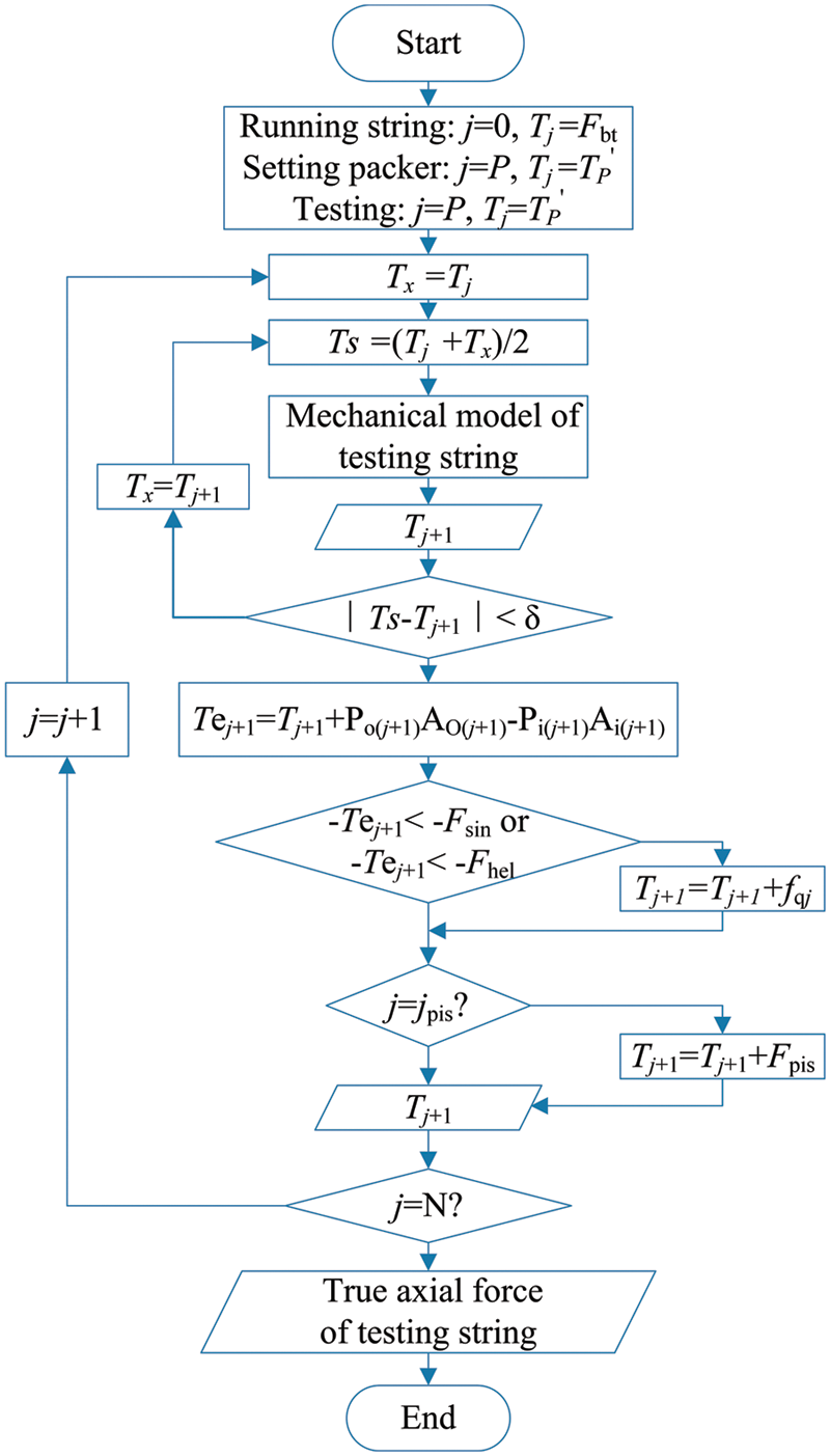
Figure 2: Flowchart of force solution of whole test string
After the test string trips into the predicted depth, the static balance is achieved under the combined action of drilling fluid force, gravity, friction, and the support reaction of the borehole wall. Therefore, when the column enters the expected depth, the boundary conditions of the mechanical model can be expressed as follows:
The axial force T0 at the bottom of the test string is the liquid force, which is taken as the starting point for calculation. Combined with Eq. (1), the true axial force at the bottom end of each unit segment of the whole string can be obtained when the tripping is completed, which is T0, T1,…, TP,…, TN from bottom to top. TP is the true axial force of the lower end face of the unit test string at the packer when the tripping is completed.
A Hydraulic setting is adopted. After the wellhead is put into the ball, the tubing is pressed to the start-up pressure difference of the packer, the slip extends and bites the casing wall, and the packer is no longer moved. In this process, the packer string will deform under the combined action of the piston effect and the ballooning effect formed by pressure. Under the fixed constraint of slip, the deformation will be transformed into force, and new boundary conditions will be formed at the packer. Therefore, when the column setting is completed, the force at the packer can be expressed as:
where
where TP is the axial force of the lower end face of the unit test string at the packer when the setting is completed, N; ΔF1 is the variable axial force formed in the process of seating compression, N; pac is the serial number of the test string at the packer; hpac is the depth of the packer, m; ΔL2 and ΔL3 are the total deformation of the test string due to the ballooning effect and piston effect in the processes of seating and pressing, respectively. m; Asn is the cross-sectional area of the n-sleeve test string, N.
The loading condition of the string after the completion of the setting will be the initial condition for the loading analysis of the test string during the operation after the setting. At the same time, the temperature and pressure changes caused by the test operation after the setting will produce various types of stress. Since the test string cannot be moved at the packer and wellhead, the stress will act on the string at the packer, forming a new boundary condition. The force at the packer can be expressed as:
where
where TP″ is the true axial force of the lower end face of the test string unit segment at the packer (working condition) after setting, N; ΔF2 is the temperature and pressure changes formed by the change of axial force, N; ΔL1, ΔL2, ΔL3, and ΔL4 represent the test string’s total deformation due to the temperature effect, ballooning effect, piston effect, and buckling effect, respectively, m.
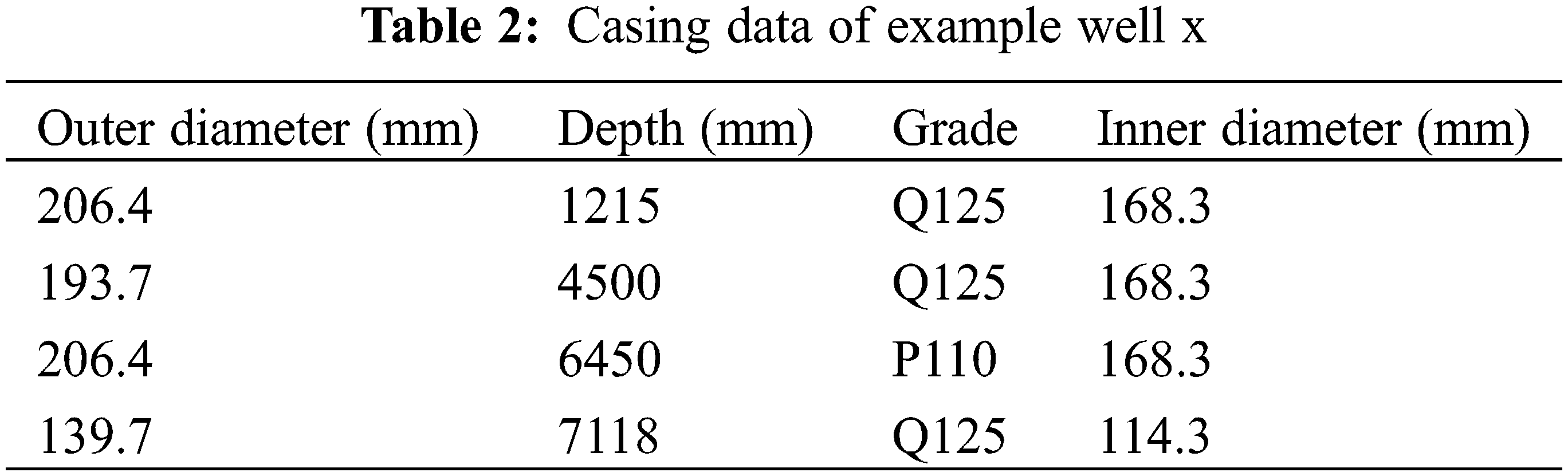
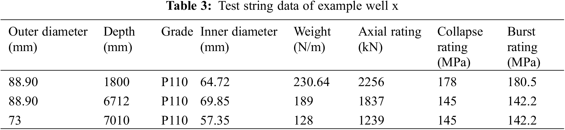
Taking the test string of a certain high-temperature and high-pressure gas-well as the research object, the mechanical analysis of the test string is carried out. The well depth structure is a continuous well, the completion depth is 7123 m, the test formation is 6950.5–7010 m, the packer depth is 6700 m, the surface temperature is 16°C, and the converted geothermal gradient is 2.01°C. The basic parameters of the test string are presented in Table 2, and the casing parameters are shown in Table 3.
According to the model in this paper and the solving block diagram, the mechanical analysis of the test string of the example well x is carried out. The axial force distribution of the test string along the well depth under different test conditions is shown in Fig. 3.
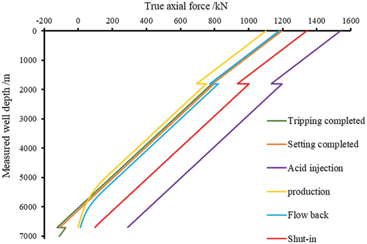
Figure 3: True axial force of the test string along the well depth under different working conditions
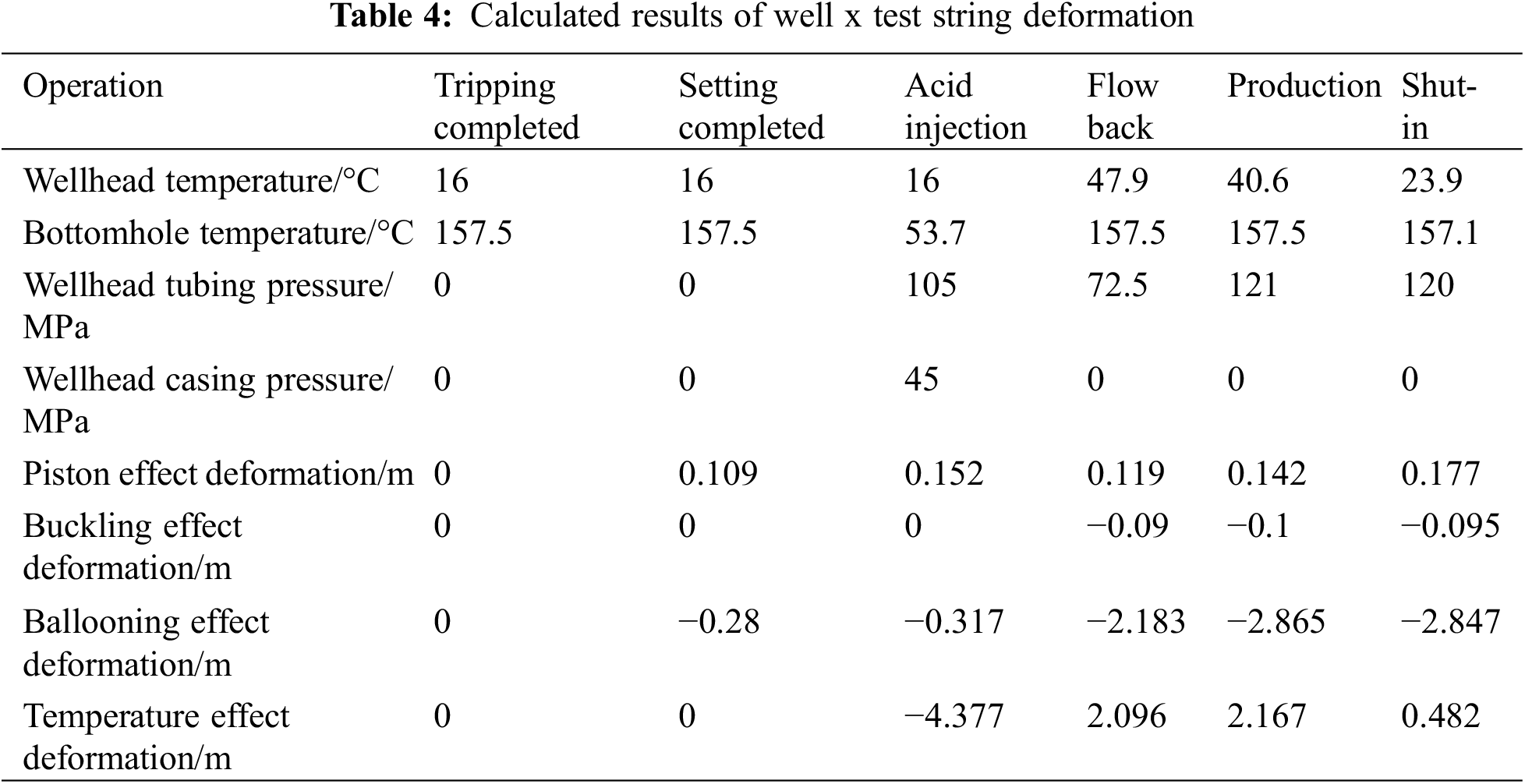
The deformation of test string under different test conditions is presented in Table 4.
The true axial distribution of test string along well depth under different production rates is shown in Fig. 4.
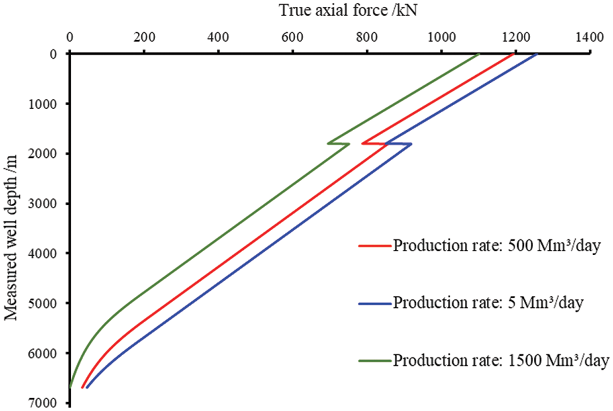
Figure 4: True axial force of the test string along the well depth under different production capacity
As shown in Fig. 4, with the increase in production, the true axial force of the test string along the well depth is seriously nonlinear. The reason is that the wellbore temperature increases with the increase in production, and the temperature effect leads to an increase in the elongation of the string. Under the constraint of the packer end, the effective axial compression force of the test string increases gradually, and the string buckling is serious. The buckling of the test string causes an increase in the friction resistance, resulting in the nonlinear situation of the true axial force curve.
1) According to the operational characteristics of the test string in high-temperature and high-pressure gas wells, the mechanical model and solution method of the test string are established by comprehensively considering such factors as temperature, pressure, wellbore trajectory, and buckling, and combining the deformation and string constraint conditions caused by temperature and pressure changes in the processes of entry, setting, and test operations.
2) The force of test string in well x under different working conditions is analyzed using the mechanical model derived in this paper. The feasibility of the mechanical model and solution method is verified.
3) It is concluded from a sensitivity analysis of the true axial force of the test string under different yields that the higher the yield, the more severe the buckling deformation of the test string. It is necessary to select the appropriate yield to ensure the safe production of the test string.
Funding Statement: The author received no specific funding for this study.
Conflicts of Interest: The author declares that they have no conflicts of interest to report regarding the present study.
References
1. Johancsik, C. A., Friesen, D. B., Dawson, R. (1984). Torque and drag in directional wells-prediction and measurement. Journal of Petroleum Technology, 36(6), 987–992. https://doi.org/10.2118/11380-PA [Google Scholar] [CrossRef]
2. Sheppard, M. C., Wick, C., Burgess, T. (1987). Designing well paths to reduce drag and torque. SPE Drilling Engineering, 2(4), 344–350. https://doi.org/10.2118/15463-PA [Google Scholar] [CrossRef]
3. Ho, H. S. (1988). An improved modeling program for computing the torque and drag in directional and deep wells. SPE Annual Technical Conference and Exhibition, Houston, Texas, USA. [Google Scholar]
4. Maidla, E., Wojtanowicz, A. K. (1987). Field comparison of 2-D and 3-D methods for the borehole friction evaluation in directional wells. SPE Annual Technical Conference and Exhibition, Dallas, Texas. https://doi.org/10.2118/16663-MS [Google Scholar] [CrossRef]
5. Zhang, J. Q., Sun, X. Z., Zhao, J. P. (1989). A preliminary study of frictional drag model and its application to directional wells. Journal of DAQING Petroleum Institute, 13(4), 23–38. [Google Scholar]
6. Han, Z. Y. (1993). Study on 3-D and 2-D models of drill string torque and drag in hole. Journal of the University of Petroleum, 17, 44–50. [Google Scholar]
7. Gao, D. L. (2006). Downhole tubular mechanics and its applications. China: China University of Petroleum Press. [Google Scholar]
8. Lubinski, A. (1950). A study of the buckling of rotary drilling strings. API Drilling & Production Practice, 5, 178–214. [Google Scholar]
9. Paslay, P. R., Bogy, D. B. (1964). The stability of a circular rod laterally constrained to be in contact with an inclined circular cylinder. Journal of Applied Mechanics, 31(4), 605–610. https://doi.org/10.1115/1.3629721 [Google Scholar] [CrossRef]
10. Wu, J. (1992). Buckling behavior of pipes in directional and horizontal wells (Ph.D. Thesis). A&M University, Texas, AM. [Google Scholar]
11. Mitchell, R. F. (1999). A buckling criterion for constant-curvature wellbores. SPE Journal, 4(4), 349–352. https://doi.org/10.2118/57896-PA [Google Scholar] [CrossRef]
12. Mitchell, R. F. (2005). The pitch of helically buckled pipe. SPE IADC Drilling Conference, Amsterdam, Netherlands.SPE-92212-MS. [Google Scholar]
13. Li, X., Gao, D. L. (2019). Study on mud weight window prediction model and safety additional value of horizontal well in shales considering effects of well’s extended-reach limit. Journal of Petroleum Science and Engineering, 173(3), 579–587. https://doi.org/10.1016/j.petrol.2018.10.054 [Google Scholar] [CrossRef]
14. Lian, Z. H., Wang, T., Mou, Y. S. (2021). Buckling behavior of completion string in complex mechanical environment and preventive measures. Science Technology and Engineering, 21(5), 1758–1763. [Google Scholar]
15. Robello, S. (2012). Effective force and true force: What are they? IADC/SPE Drilling Conference and Exhibition. San Diego, California, USA. [Google Scholar]
16. Chen, W. K., Feng, D. (2019). Study on tubing joined pattern of drill-grinding string in horizontal well and safety analysis of tripping. Journal of Safety Science and Technology, 15(11), 43–49. [Google Scholar]
17. Liu, X. K., Ding, L. L., Li, Y. F. (2020). Study of the buckling behavior of completion strings for ultra-deep gas wells. China Petroleum Machinery, 48(2), 29–34. [Google Scholar]
Cite This Article
 Copyright © 2023 The Author(s). Published by Tech Science Press.
This work is licensed under a Creative Commons Attribution 4.0 International License , which permits unrestricted use, distribution, and reproduction in any medium, provided the original work is properly cited.
 Downloads
 Citation Tools