
 Submit a Paper
 Propose a Special lssue
 Open Access
ARTICLE
Study on Rotational Effects of Modern Turbine Blade on Coolant Injecting Nozzle Position with Film Cooling and Vortex Composite Performance
1 School of Energy and Power Engineering, Xi’an Jiaotong University, Xi’an, 710049, China
2 School of Mechanical and Aerospace Engineering, College of Engineering, Nanyang Technological University, 639798, Singapore
3 Shaanxi Engineering Laboratory of Turbomachinery and Power Equipment, Xi’an, 710049, China
* Corresponding Authors: Eddie Yin Kwee Ng. Email: ; Liang Li. Email:
Frontiers in Heat and Mass Transfer 2023, 21, 1-31. https://doi.org/10.32604/fhmt.2023.045510
Received 29 August 2023; Accepted 23 October 2023; Issue published 30 November 2023
 View Full Text
 Download PDF
Abstract
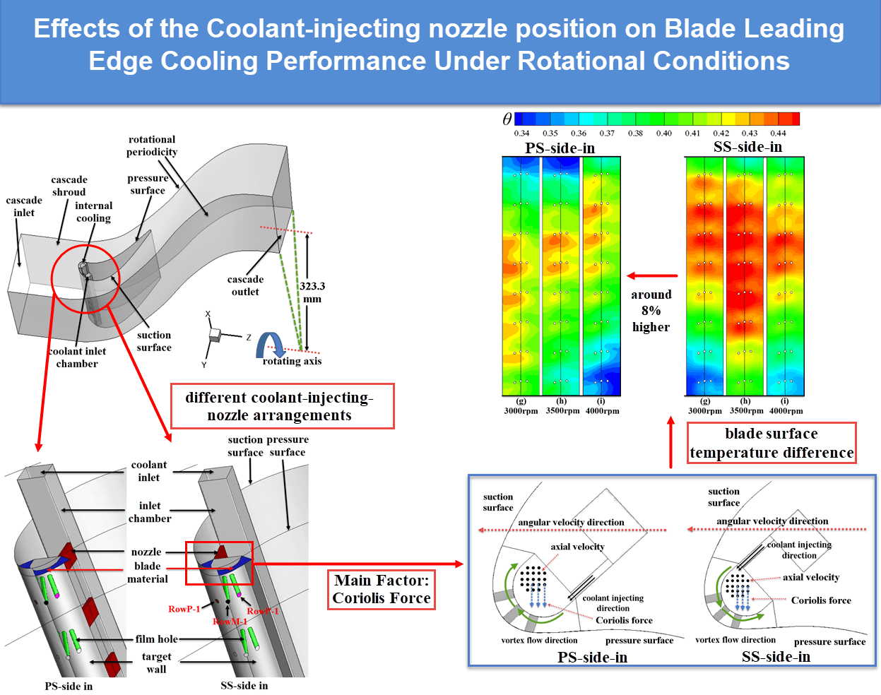
The flow structure of the vortex cooling is asymmetrical compared to the traditional gas turbine leading edge cooling, such as the impingement cooling and the axial flow cooling. This asymmetrical property will affect the cooling performance in the blade leading edge, whereas such effects are not found in most of the studies on vortex cooling due to the neglect of the mainstream flow in the airfoil channel. This study involves the mainstream flow field and the rotational effects based on the profile of the GE E3 blade to reveal the mechanism of the asymmetrical flow structure effects. The nozzle position on the characteristics of the vortex and film composite cooling in the turbine rotating blade leading edge is numerically investigated. The cool-ant injecting nozzles are set at the side of the pressure surface (PS-side-in) vs. that is set at the side of the suction surface (SS-side-in) to compare the cooling characteristics at the rotating speed range of 0–4000 rpm with fluid and thermal conjugate approach. Results show that the nozzle position presents different influences under low and higher rotational speeds. As for the mainstream flow, rotation makes the stagnation line move from the pressure surface side to the suction surface side, which changes the coolant film attachment on the blade leading edge surface. The position of nozzles, however, indicates limited influence on the coolant film flow. As for the internal channel vortex flow characteristics, the coolant injected from the nozzles forms a high-velocity region near the target wall, which brings about enhancing convective heat transfer. The flow direction of the vortex flow near the internal channel wall is opposite and aligns with the direction of Coriolis force in both the PS-side-in and SS-side-in, respectively. Therefore, the Coriolis force augments the convective heat transfer intensity of the vortex cooling in the internal channel in SS-side-in while weakening the internal heat transfer in PS-side-in. Such effects become more intense with higher rotational speed. The blade surface temperature decreases as the Coriolis force increases the internal heat transfer intensity. The SS-side-in suggests a superior composite cooling performance under the relatively higher rotating speed. The SS-side-in structure is recommended in the gas turbine blade leading edge running at a higher rotating speed.Graphic Abstract
Keywords
Highlights
| • | The asymmetrical mainstream flow effects on the cooling performance are revealed. |
| • | The “asymmetrical property” of the vortex cooling is discovered and analyzed. |
| • | The Coriolis force is the root cause that brings about the “asymmetrical property”. |
| • | A more reasonable and flexible evaluation criterion of cooling performance is utilized. |
| Nomenclature | |
| c | Absolute velocity of the mainstream inlet flow (m/s) |
| Dc | Hydraulic diameter of coolant supply chamber inlet (mm) |
| f | The loss of pressure |
| f0 | Blasius friction |
| L | Vortex chamber axial length |
| Mc | The mass flow of the coolant flow at the internal inlet |
| Mc0 | The mass flow of the coolant flow at the internal inlet at stationary case (0 rpm) |
| n | Alterable weighting index |
| Nu | Nusselt number |
| Nua | Area-averaged Nusselt number of the target wall |
| Pr | Prandtl number |
| Pin | Mean pressure of the coolant flow at internal inlet |
| Pout | Mean pressure of the film hole channel internal side |
| qw | Wall heat flux (W/mm−2) |
| ReD | Reynolds number of the flow in the vortex chamber |
| T | Temperature (K) |
| Tw | Target wall temperature (K) |
| Tc | Coolant temperature at internal inlet (K) |
| T∞ | Cascade inlet flow temperature (K) |
| u | Angular velocity (rad/s) |
| Ucf | Coolant velocity at the film hole (m/s) |
| Vj | Velocity of the coolant flow at internal inlet (m/s) |
| Vyz | Coolant velocity on XY section (m/s) |
| Vy | Y-componenet of the coolant velocity in the rotational frame |
| Vz | Z-componenet of the coolant velocity in the rotational frame |
| w | Mainstream flow velocity relative to the rotation frame (m/s) |
| θ | Dimensionless temperature |
| ε | The rate of dissipation of turbulent kinetic energy |
| ω | Rotational speed (rpm) |
| ρ | Fluid density (kg/m3) |
| ρc | Coolant density at the internal inlet (kg/m3) |
| ρcf | Coolant density at the film hole (kg/m3) |
| ρ∞ | Mainstream fluid density (kg/m3) |
| μ | fluid dynamic viscosity, kg/(mm·s) |
| λ | fluid thermal conductivity, W/(mm·K) |
| φ | Aerodynamic parameter evaluating the cooling performance in the current study |
| Φ | Aerodynamic parameter evaluating the cooling performance in the previous studies |
| Abbreviation | |
| BLE | Blade leading edge |
| IVC | Internal vortex cooling |
| EFC | External film cooling |
| delta | Area-averaged dimensionless temperature θ on the blade surface |
| VFCC | Vortex and film composite cooling |
| GCI | Grid Convergence Index |
| MF | Mainstream flow |
| SST~γ-θ | SST k-ω with γ-θ transition model |
| SST | SST k-ω model |
| SL | Stagnation line |
Gas turbines have gained significant popularity in various applications, such as aircraft, marine propulsions, and electricity generation, and they continue to undergo advancements. As one of the crucial factors contributing to the enhanced engine power and operating efficiency, the inlet temperature of the turbine part has surpassed 1644–1700 K. Consequently, the working conditions for turbine blades have become increasingly severe [1]. To counteract this challenge while minimizing coolant consumption, effective cooling methods have become imperative. Vortex cooling is a specialized approach for cooling the turbine blade leading-edge part. Vortex cooling combines the advantages of intense convective heat transfer observed in impingement cooling and the uniform heat flux distribution associated with axial flow. In practical scenarios, blade leading edge cooling (such as vortex cooling) is usually utilized in conjunction with external film cooling (EFC) in the blade leading edge (BLE), and such a cooling method is called the vortex and film composite cooling (VFCC) [1].
The heat transfer performance of composite film and vortex cooling is influenced by three primary factors. These factors encompass the geometrical parameters, the mass transfer between the internal vortex cooling (IVC) flow and the mainstream flow (MF), the heat transfer brought about by the blade material, and the aerodynamic factors (injection blowing rate ratio, rotational speed, temperature ratio, etc.). Researchers have conducted many studies on the IVC and EFC conception as cited in the following text.
In terms of IVC, earlier research mainly focused on the swirl-flow structure generation and measurement. Kreith et al. [2] combined the twisted tape with a cylinder channel to generate a swirl flow field with the axial inlet flow. They found that the swirl velocity reduced by 80%–90% at around 50 times diameter downstream along the cylinder channel axis. Ling et al. [3] utilized the tangential nozzle and measured the target surface temperature using the transient liquid crystal technique. Results showed that the Reynolds number of the coolant injecting flow led to a distinct heat transfer intensity increment. Besides, the near-wall velocity distribution of the vortex flow field was measured in detail. Most of the recent studies on internal vortex cooling (IVC) focused on the influences of geometrical and aerodynamic factors on the IVC performance. Liu et al. [4–6] systematically studied the influences of the Reynolds number, ratio of vortex chamber radius to slot height and the jet nozzle aspect ratio based on the experimental rig Ling et al. [3]. Fan et al. [7] experimentally tested the influences of the coolant inlet Reynolds Number on the heat transfer intensity of the half-cylinder IVC structure. Mousavi et al. [8] placed several tangential cooling injecting nozzles at the identical axial position of the vortex chamber. Results indicated that the increasing nozzle amount could slow down the decay of the vortex flow circumferentially. Bigger et al. [9] utilized the DES (Detached Eddy Simulation) to capture the decay of the circumferential velocity in the vortex chamber. In addition, Bigger et al. [10] used the thermochromic liquid crystals technique to experimentally investigate the influences of the outlet conditions on the heat transfer intensity of vortex cooling. Kusterer et al. [11] merged part of the two cylinders and obtained a new vortex chamber called the double swirl chamber. The coolant injected into the double swirl chamber would generate two anti-rotating large-scale vortices. Lin et al. [12,13] studied the heat transfer and pressure loss of the double swirl chamber and found higher heat transfer intensity or lower pressure loss achieved under specific aerodynamic conditions. Liu et al. [14] introduced the dimples into the inner surface of the vortex chamber and found that the total heat transfer intensity increases by up to 7.2% compared to the original structure.
As for external film cooling (EFC), researchers mainly focused on investigating the geometrical factors that influence the performance of the EFC. They also tried to introduce some special structures to optimize the EFC performance. Zhao et al. [15] utilized film holes to connect the internal axial flow cooling channel with the MF. They numerically compared the adiabatic EFC efficiency of the cylindrical film holes and fan-shaped film holes. Zhu et al. [16] numerically compared the showerhead EFC performance of the cylindrical film hole, fan-shaped film hole and the converging round-to-slot film hole in the blade leading edge (BLE). Ye et al. [17,18] introduced the groove structure into the showerhead film hole on the BLE to optimize the EFC effectiveness.
In the previous work, it can be concluded that systematic and detailed investigations have been carried out separately on the internal vortex cooling (IVC) and the external film cooling (EFC). Whereas the IVC and EFC are combined to cool the BLE. Although internal cooling is involved in the research on the EFC above, the internal cooling in those studies is axial flow cooling, which is different from impingement cooling or the IVC in the practical blade leading edge (BLE).
Some researchers focused on the internal vortex cooling (IVC) characteristics in practical situations. In those studies, the IVC conception is placed in the BLE. Besides, they merged the film holes with the IVC structure to study the performance of the vortex and film composite cooling (VFCC). Fan et al. [19] combined a row of film holes with the IVC structure and studied the film hole circumferential angle effect. Du et al. [20] numerically researched the rotation effects on the IVC based on the VFCC established by Fan et al. [19]. Li et al. [21] introduced a rectangular channel as the airfoil cascade into the IVC model put forward by Fan et al. [19] and explored the IVC intensity as well as the adiabatic EFC effectiveness. Zhang et al. [22] experimentally explored the performance of the VFCC influenced by the MF. The IVC chamber was placed in a symmetrical BLE, where the MF flow field near the BLE was different from the practical situation. Wang et al. [23] numerically studied the nozzle position effect on the VFCC performance in a vane of GE E3 (General Electric Energy Efficient Engine). In that case, the mainstream flow (MF) flow field near the BLE was asymmetrical. The results showed that the position of the internal coolant injecting nozzles would impact the heat transfer of the IVC and the coverage level of the external film cooling (EFC). However, the heat conduction of the blade material was not considered in their study.
From the foregoing discussion, most of the studies were linked to the impacting mechanism of aerodynamic and geometrical parameters on internal vortex cooling (IVC) performance. Nevertheless, there remains a limited number of investigations on predicting and analyzing the performance of IVC in mainstream flow (MF) cascades. Vortex and film composite cooling (VFCC), which combines external film cooling (EFC) and IVC, is commonly employed to cool the BLE in practical cases. The characteristics of the VFCC are dominated by the coverage of EFC, heat transfer of IVC, heat transfer through the blade material, and the effects of rotation. Nearly all the studies mentioned above used a semi-cylinder configuration to substitute the profile of the BLE, such as the experiment carried out by Zhang et al. [22]. In those simulations, the MF was symmetrical. However, it should be noted that the MF flow field in blade cascades is inherently asymmetrical. Therefore, those studies on the MF effects of the VFCC are quite different from the practical situation. In addition, the heat conduction through the blade material would connect the hot gas in the MF and the IVC flow. This heat conduction has a simultaneous impact on the heat transfer of the internal cooling and the effectiveness of the EFC. Consequently, it is essential to recognize that the fluid-thermal coupling simulating method is required, which does not exist in the previous studies on the VFCC.
To further investigate the characteristics of the vortex and film composite cooling (VFCC), it is imperative to conduct comprehensive investigations that consider asymmetrical mainstream flow (MF) effects, the influence of the fluid-thermal coupling, and the effects of rotation and this is the strength or contribution of the current paper. A VFCC model is put forward and studied within the asymmetrical MF. Specifically, the structure of the internal vortex cooling (IVC) model is referred to the model in Fan et al. [7]. The MF cascade structure and the blade profile are put forward based on the base stage1 blade in the test rig [24]. The mainstream flow (MF) flow field in the cascade will be asymmetrical. In our paper, the conjugate approach is carried out by introducing the blade material solid part to connect the MF flow field and the internal vortex flow field. The VFCC models with different coolant injection nozzle arrangements are established. The temperature distribution of the blade surface, the heat transfer distribution of the IVC, and the coolant film coverage of the external film cooling (EFC) are calculated under different rotational speeds. This work might contribute to a more thorough understanding of the complex interactions of BLE cooling and provide valuable references for the application of IVC in practical scenarios.
2 Structure and Numerical Methods
For convenience, the following technical phrases will be substituted to the respective abbreviations: internal vortex cooling (IVC), external film cooling (EFC), dimensionless temperature (delta), vortex and film composite cooling (VFCC), blade leading edge (BLE), mainstream flow (MF), SST k-ω with γ-θ transition model (SST~γ-θ), SST k-ω model (SST), the standard k-ω model (k-ω), and stagnation line (SL).
Fig. 1 illustrates the three-dimensional computational model. The boundaries are also pointed out. The calculation model, as depicted in Figs. 1a and 1b, comprises the cascade with the blade, film hole channels, internal vortex cooling (IVC) chambers, and the blade leading edge (BLE) material part of the blade as one integrated entity. The vortex and film composite cooling (VFCC) system consists of an inlet chamber connecting with a semi-cylinder vortex chamber (the connecting part consists of eight coolant injection nozzles) and twenty-four film hole channels (the coolant inside the vortex chamber could only enter the mainstream flow (MF) cascade through the film holes). The upstream segment of the MF channel is set to the length of the blade chord, and the downstream segment of the MF channel is set to 1.5 times the length of the blade chord. For clarity, Fig. 1 presents only a partial view of the upstream and downstream segments. The extended upstream segment ensures the formation of the MF boundary layer before impacting the BLE surface.

Figure 1: The three-dimensional computational model
Fig. 2 presents the top view of the structure of the blade leading edge (BLE). Given the internal vortex cooling (IVC) structure is asymmetrical compared to the classical symmetrical cooling conception, such as impingement cooling, there are mainly two types of nozzle arrangements, as indicated in Fig. 2. The case in which the nozzles are set near the side of the pressure surface is called “PS-side-in” case, and the case in which the nozzles set near the side of the suction surface is called “SS-side-in” case in the following text. In Fig. 2b, there are two sections of the BLE: the segment of the pressure surface and the segment of the suction surface. Our analysis primarily focuses on the isotherms distribution on the surface of the BLE, specifically on the suction surface leading edge part and the pressure surface leading edge part depicted in Fig. 2b. The film holes located on the segment of the pressure surface, the segment of the suction surface, and the position between them are designated as RowP, RowS, and RowM, respectively.

Figure 2: Sketch of the two cases with different nozzle position
Fig. 3 exhibits the sizes of the vortex chamber of the vortex and film composite cooling (VFCC) model. The incline angle of the film holes with the showerhead configuration is set to 25° to blade height direction, with a 30° angle between adjacent rows of film holes (close to the GE E3 stage1 blade configuration [24]). Such an inclined angle setting of film hole configuration in the blade leading edge (BLE) is commonly applied in gas turbine blades as the coolant will be forced to move towards the blade height direction due to the influence of the centrifugal force. The film hole channels at different heights are labeled as Row1, Row2,…, Row8. The entire computational model is set as the rotational domain. The rotational axis is the Z-axis, with a length of 364 mm [24] from the rotational axis to the hub wall of the cascade.
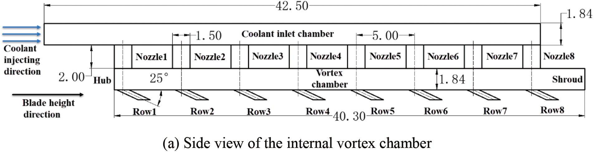

Figure 3: Internal vortex cooling (IVC) structure sizes of the vortex and film composite cooling (VFCC) model
As for the coolant flow path, the coolant initially blows into the inlet chamber from the boundary called internal inlet. Next, the coolant flows through the coolant injecting nozzles, and enters the vortex chamber as the tangential jet. Finally, the coolant flows through the film hole channels into the cascade, and then becomes the film attached to the blade surface or mixes with the hot gas of the mainstream flow (MF). As for the MF, in the stationary case, the MF hot gas flows into the cascade with an angle 30° to the Y-axis in the absolute coordinate.
The profile of the blade, the configuration and sizes of the film holes, and the rotating axis setting in our setup are identical to the test rig used by NASA [24]. Furthermore, the internal vortex cooling (IVC) structure was replicated and scaled from the experimental rig developed by Fan et al. [7].
Figs. 4a and 4b display a whole view and a partial view of the mesh, respectively. To generate the unstructured mesh with requested high-quality, the commercial software ANSYS 12.1 was utilized. The connecting surfaces between the solid domains and the fluid domains are set to the interfaces. In order to achieve low y+ values, at least 12 prism layers were implemented in the regions near the boundary of the walls. Fig. 4c presents the y+ contour on the pressure surface under one of the calculating conditions. It could be captured that the y+ is lower than 1 on the pressure surface of the blade. The y+ values on other walls are all checked to ensure y+ is lower than 1. This approach ensures that the flow field in the regions near the wall is calculated directly rather than relying on empirical wall functions, by which the calculating results will be much more accurate.

Figure 4: Schematic of the calculating mesh and y+ checking
2.3 Solution Procedure and Boundary Conditions
The governing equations is shown as follows:
In this conservative Navier-Stokes equations, where
• U is the solution vector and represents the conservative variables
F G H mean the inviscid flux vectors
where
• ρ represents density
• u, v, w represents the velocity on the X, Y and Z direction, respectively
• p represents pressure
• E represents the total energy per mass
Fv Gv Hv mean the viscous flux vectors
• τ represents the stress
• λ represents the conductivity
To effectively solve the governing equations above by numerical methods, the ideal gas law as well as the turbulence model are required.
In the study conducted by Du et al. [20], the flow field and heat transfer distribution of internal vortex cooling (IVC) influenced by rotation were numerically investigated using the standard k-ω turbulence model coupled with the three-dimensional steady viscous RANS equation (Reynolds averaged Navier-Stokes). Similarly, Zhang et al. [22] and Wang et al. [23] examined the blade surface temperature, heat transfer intensity and flow field of the vortex and film composite cooling (VFCC) under the effect of the mainstream flow (MF) solving the RANS equation coupled with the realizable k-ε model or SST~γ-θ, respectively. These studies demonstrated that the two-equation turbulence models employed were effective in capturing flow field distribution and accurately simulating the distribution of the heat transfer affected by rotation. Consequently, our research also adopts the 3D steady viscous RANS model together with the turbulence model of two-equation for calculation, which is applicable in engineering as the previous studies. If the hot spot in the MF inlet flow is involved, the transient unsteady simulation should be conducted to capture the interaction process between the coolant jet of the external film cooling (EFC) flow and the hot spot.
For discretizing the convection term, we applied the high-resolution correction in the second-order format. Initially, the timestep is set to 10−4 s and is updated during iteration, referring to the timescale factor value of 0.05. To ensure convergence, the monitors are set based on those critical variables throughout the iteration step. These variables include Reynolds numbers of the coolant inlet flow as well as the cascade inlet flow, the averaged target wall Nusselt number of the internal cooling chamber, the dimensionless temperature (delta) of area-averaged blade leading surface, and the film hole channel massflow rate.
The definition of Nusselt number Nu is identical to the previous studies on the IVC performance. The Nusselt Number Nu is defined as:
where
• qw is the heat flux of the target wall (W/m2)
• Dc means the cross section hydraulic diameter of internal vortex chamber (m)
• λ represents the fluid thermal conductivity (W/(m·K))
• Tw represents the target wall temperature
The dimensionless temperature θ is:
• T∞ stands for the cascade inlet flow temperature
• Tc represents the coolant flow temperature of internal inlet
The higher θ indicates the lower actual temperature of the fluid or the blade wall. Convergence is achieved when the oscillation amplitude of the profiles of these variables varying with the iteration step is lower than 5% of the average values.
Table 1 presents the boundary conditions set in the simulation. As for the mainstream flow (MF) cascade boundaries, the total temperature of the cascade inlet, the total pressure of the cascade inlet, and the static pressure of the cascade outlet are 206.431 kPa, 683 K, and 68.81 kPa, respectively. These values are obtained from experimental data in NASA experiments [24]. The turbulent intensity of the cascade inlet is set to a high level of 10%. As for the boundaries of the internal cooling chambers, the inlet total temperature is 352 K, while the turbulent intensity of the internal inlet and the total pressure of the internal inlet are medium (5%) and 360 kPa, respectively. All the boundary conditions mentioned above are set based on the stationary coordinate (absolute coordinate). All walls are treated as adiabatic and non-slip walls. The working medium is assumed to be the air ideal gas. The material of the solid is set as steel whose thermal conductivity is 60.5 W/(m·K), as the formula and property of the alloy of the gas turbine blade cannot be simply defined. The variation of the thermal conductivity vs. temperature will be required if the researchers get interested, which is not the focus of the current research.

In addition, the reason for the selection of the range of the rotational speeds is explained as follows: in GE E3 experiment [24], the rotational velocity is set within 2000–8000 rpm. And the range of the rotational speeds in the current study is 0–4000 rpm. On the one hand, the current investigation is carried out based on the experiment rig of GE E3 experiment. It is reasonable to select the range of rotation speeds within the range of the GE E3 experiment conditions. On the other hand, the low-rotation speeds are also involved, which is important to reveal the mechanism of the asymmetrical property by the comparison between the high-rotational speed cases and the low-rotational speed cases. Besides, the range of 2000–4000 rpm stays within the variable operating conditions of the 60 Hz power generation gas turbine, such as the M701F engine in the combined cycle power generation.
2.4 Grid Independence Analysis
To reduce numerical uncertainty and discretization errors, a grid invariant analysis is performed. This test helps determine the appropriate number of nodes for the simulation. In this analysis, the case with an angular velocity of 3000 rpm is selected to conduct the grid independence analysis. There are three grids generated with the same growing rate at X-, Y-, and Z- directions, resulting in node numbers of 2.70 million, 7.42 million, and 18.79 million, respectively. All three grids undergo smoothing, and the mesh quality standards are thoroughly checked prior to calculation. In the traditional grid independence method, researchers will prepare around 6~7 sets of girds and utilize them to calculate the flow field or heat transfer parameters. The profile of certain parameters will initially fluctuate, gradually converge and finally remain almost unchanged with the increasing mesh number. This method is time-consuming. Celik et al. [25] described a grid independence analysis method (Grid Convergence Method), which has been evaluated over several hundred CFD cases according to their description. This time-saving method is utilized in this chapter.
The area-averaged delta on the suction surface part θS and the pressure surface part θP of the blade leading edge (BLE), along with the area-averaged Nusselt number on the target wall of the internal vortex cooling (IVC) chamber Nua, are calculated and exhibited in Table 2. Additionally, Fig. 5 illustrates the distribution of the coolant flow pressure in the vortex chamber, accompanied by the error bars of the numerical uncertainty. The grid with a node number of 7.42 million is used for calculating the pressure distribution, as shown in Fig. 5. The numerical uncertainty is evaluated using the GCIfine method put forward by Celik et al. [25]. In their methods, an extrapolation value will be obtained by solving the GCIfine equation utilizing the computational results calculated from a coarse, a medium and a fine grid. The numerical uncertainty is calculated based on the extrapolation value and with the results from those three grids. As shown in Table 2, the maximum numerical uncertainty does not exceed 5% of the pressure distribution solution.

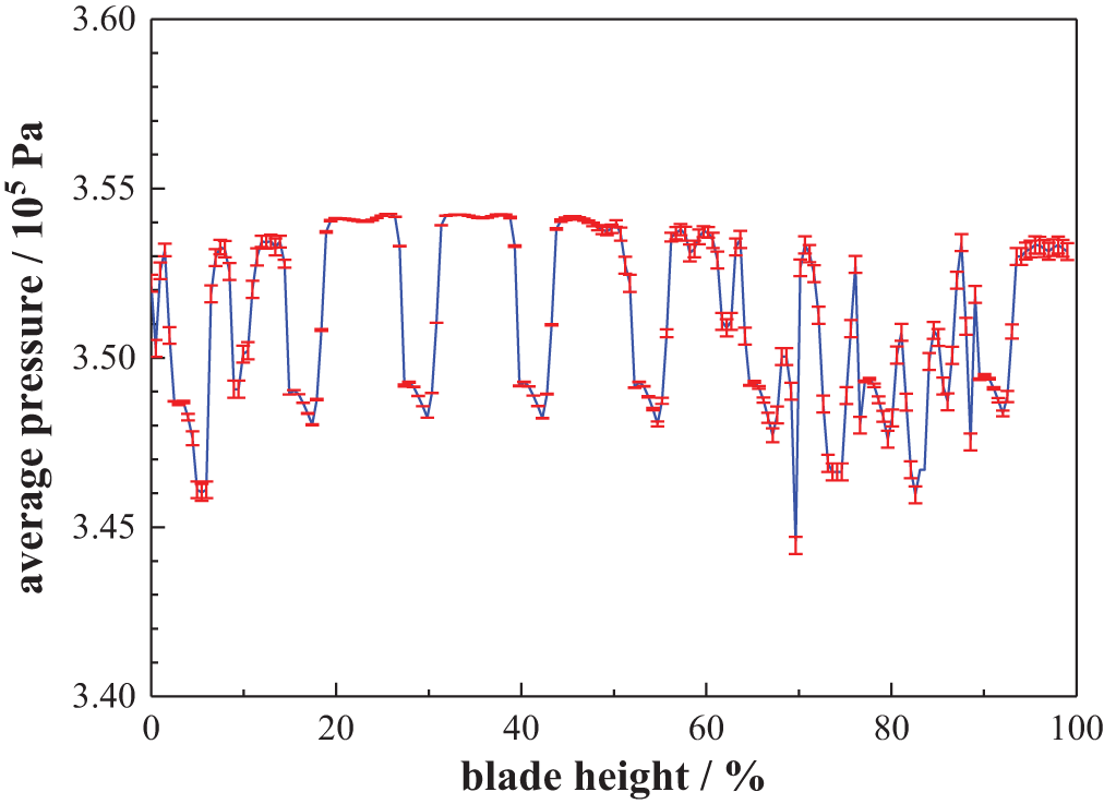
Figure 5: Profile of the coolant flow pressure in the vortex chamber along blade height with the numerical uncertainty
2.5 Turbulence Model Verification
To obtain accurate and reliable numerical results, the selection of an appropriate turbulence model is crucial. Wang et al. [23] have demonstrated that the SST~γ-θ exhibits superior simulation accuracy to the SST and the k-ω1, as illustrated in Fig. 6. In Fig. 6, the black dots represent the experimental data, and the solid-lines with color represent the simulation results. Fig. 6a shows a flat board film cooling experiment carried out by Kohli et al. [26], where the SST~γ-θ demonstrates superior performance in predicting the distribution of the film cooling effectiveness. This model accurately captures the laminar-to-turbulent transition at the downstream region of the film hole.

Figure 6: Comparison of the prediction data obtained from the turbulence models to the experiment data
In Figs. 6b and 6c, a comparison is shown between simulation and experimental data from the NASA GE E3 experiment [24]. All three turbulence models adequately predict the distribution of the vane efficiency. However, discrepancies between the numerical results and experimental data become more pronounced within the blade height range of 5% to 40%. Such a phenomenon may be attributed to non-uniform inlet flow field conditions or fluctuations in inlet flow velocity during the experiment. Given both the film cooling flow and the cascade flow are involved in studying the vortex and film composite cooling (VFCC) characteristics, the turbulence model prediction on the film cooling experiment [26] and the cascade flow experiment [24] are all examined to choose the most suitable model. As indicated in Fig. 6, the
In a study by Safi et al. [27], A numerical investigation was conducted to explore the rotational influences on the impingement cooling performance in the blade leading edge (BLE) of gas turbines. The simulations covered a rotating speed range of 0–750 rpm, revealing the underlying mechanism of rotational influences on the vortex and film composite cooling (VFCC) performance in the BLE of gas turbines. In the current research, similar simulations are performed within an extended rotating speed range of 0–4000 rpm, which aligns with the range studied by Safi et al. [27].
3.1 Rotation Influences on the External Flow
Fig. 7 shows the schematic of the direction of the mainstream flow (MF) inlet flow vs. the angular velocity. There are three types of velocity vector: the MF inlet flow absolute velocity c, the angular velocity u and the MF inlet flow velocity relative to the rotation frame w, in which c= u + w. When the angular velocity u is 0 rpm, velocity c and velocity w are identical. The angle between the velocity w and Y-axis is 30°. As the angular velocity u increases under the fixed velocity c, the angle between the velocity w and Y-axis gradually increases. A flow stagnating to the blade will bring about a line-shaped stagnation region on the blade leading edge (BLE) surface, whose position is related to the flow direction. Given the blade could be regarded as a rotation frame, it can be concluded in Fig. 7 that the stagnation region will move from the pressure surface side to the suction surface side on the BLE surface with the increasing angular velocity u. The line-shaped stagnation region is termed “SL (stagnation line)” in the following text.

Figure 7: Schema of MF velocity relative to the stationary and rotational coordinate
Fig. 8 illustrates the pressure contour and surface streamlines on the blade leading edge (BLE). The presence of stagnation lines (SL) could be observed as characterized by the opposite streamline directions on each side of these lines. At 0 rpm, the SL presents a relatively straight profile from the hub to the shroud side and is positioned to the left side of RowP. When the rotating speed rises, the SL shifts towards the suction surface of the blade and eventually settles on the left of the film hole RowS. This shift is attributed to the keeping growing norm of the circumferential velocity u as presented in the velocity triangle, leading to a direction change in the of w. Metaphorically, the upper portion of the SL moves “faster” towards the blade suction surface compared to the portion near the hub with increasing rotating speed, primarily due to the higher circumferential velocity near the shroud. This difference becomes more distinct at higher rotating speeds. Additionally, the surface streamlines gradually curve towards the side of the shroud, given the effects of the growing centrifugal force associated with the growing rotational speed. It is worth noting that the position of the SL aligns with RowP and RowM positions at 1500, 3000 and 3500 rpm, respectively. The position of the SL will affect the heat and mass transfer between the coolant film flow and the MF.

Figure 8: Pressure contour and surface streamline on the leading-edge region of the blade under all rotating speeds
Fig. 9 presents the blowing ratio variation vs. the rotating speed in PS-side-in and SS-side-in. Blowing ratio BR is defined as:
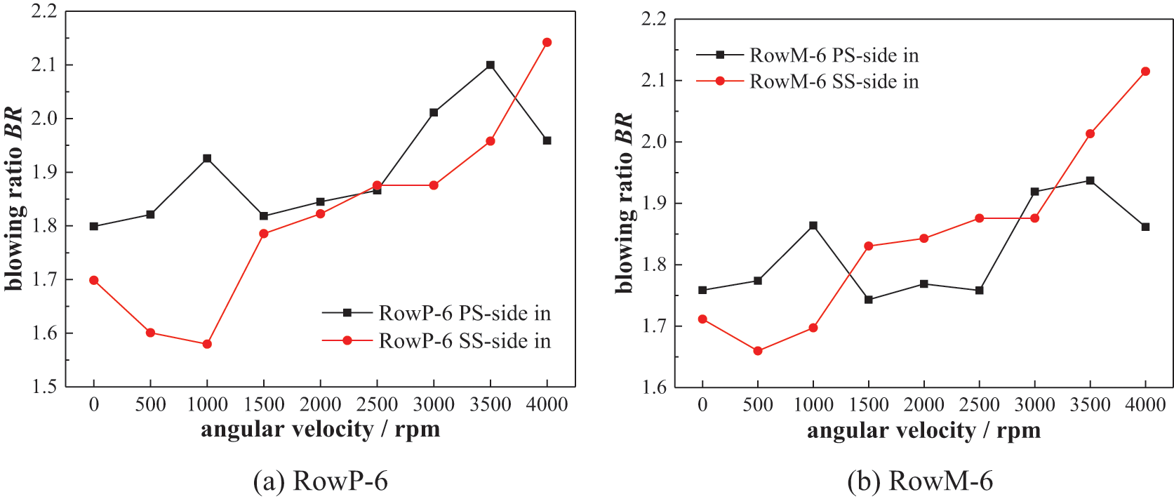

Figure 9: Blowing ratios of the film holes Row6 under all rotating speeds
The dimensionless temperature θ is:
• ρcf and ρ∞ stand for the coolant density at the film hole and the mainstream fluid density at the cascade inlet, respectively.
• Ucf and U∞ stand for the coolant velocity at the film hole and the mainstream flow velocity at the cascade inlet, respectively.
The blowing ratio indicates the momentum ratio of the coolant to the mainstream flow. RowP-6, RowM-6 and RowS-6 represent the sixth-row of film hole located at the pressure surface, the suction surface, and the position between the suction surface and pressure surface, respectively. Those three film holes’ blowing ratios fluctuate and increase with the growing rotational speed. Such a phenomenon is brought about by the enlarging centrifugal force caused by the increasing rotating speed, which, as a result, forces the coolant to move along the blade height direction. It is noteworthy that the blowing ratios of RowP-6 and RowM-6 at 0–1000 rpm are lower in PS-side-in than that in SS-side-in. The reasons are explained as follows. On the one hand, the coolant injecting nozzles stay closer to RowP in PS-side-in than SS-side-in. Hence, more coolant will flow to the MF through RowP in PS-side-in than the SS-side-in. On the other hand, the SL appears near RowP and RowM at 0–1000 rpm, which brings about higher MF pressure near RowP and RowM but lower MF pressure near RowS. In that case, in SS-side-in, a higher proportion of the coolant directly flows into the MF through RowS rather than RowP or RowM. This causes a lower blowing ratio of RowP and RowM as well as a higher blowing ratio of RowS in SS-side-in compared to PS-side-in at 0–1000 rpm. Such phenomena will bring about the difference in the performance of the vortex and film composite cooling (VFCC) in the following discussion.
Fig. 10 depicts different types of cross-sections for analysis. Section A presented in Fig. 10a locates on the axis of RowM and is parallel to the blade height. There are three types of Section A. They are located on the axis of RowP, RowM and RowS, respectively. Section A is created to ‘capture’ the external near wall flow field of the external film cooling (EFC). Section B shown in Fig. 10b locates on the blade height of Row6 and is vertical to the blade height to ‘capture’ the flow field of the internal vortex cooling (IVC).

Figure 10: Positions of the cross-sections for analysis
Fig. 11 presents the θ contour on Section A to exhibit the spreading level of the coolant film on the blade surface. Figs. 11(1), 11(2) and 11(3) illustrate the local-region θ contour near RowP-6, RowM-6 and RowS6 in PS-side-in and SS-side-in, respectively. In general, there are mainly three types of external film cooling (EFC) flow regimes under all of the rotating speed scenarios. First, the coolant jet lifts away from the surface of the blade and penetrates into the mainstream flow (MF), such as the phenomena revealed in Figs. 11(2(a)), 11(3(d)) and 11(4(f)). The coolant jet lifting off is caused by the low MF pressure at the outer side region of the film hole and the higher blowing ratio of the film hole. In that case, the coolant film thus fails to protect the blade surface from the MF hot gas sufficiently. Second, the coolant jet is suppressed by the MF to the surface of the blade and spreads on the blade surface. This phenomenon appears when the position of the SL aligns with the film hole position. At 1500 rpm, the SL stays at the position of RowP. Given the pressure and temperature of the MF near the SL position is the highest within the whole fluid domain, the coolant jet from RowP is suppressed onto the blade surface, leading to a large coolant film coverage area on the blade surface as seen in Fig. 11(2(c)). Similarly, the coolant film from RowM attaches to the surface of the blade well at 3000 rpm, as revealed in Fig. 11(3(e)). Third, the coolant jet lifts off initially and then reattaches to the surface of the blade, as shown in Figs. 11(2(f)), 11(3(a)) and 11(4). The reattachment level is affected by both the stagnation position and rotating speed. The increasing centrifugal force as a result of the increasing rotating speed makes the coolant film flow toward the side of the shroud, therefore increasing the reattachment distance, as seen in Fig. 11(4). Furthermore, the stagnation line (SL) gets closer to film hole RowS with an increasing rotating speed. The high-pressure hot gas of the MF flow around the SL, then pushes the coolant jet away and increases the reattachment zone.

Figure 11: Near-wall contour of θ on the cross-section A
The coolant film attachment normally happens under a relatively low blowing ratio and relatively high mainstream flow pressure. As shown in Fig. 11(2(c)), the mainstream flow pressure in the region near RowP-6 and blowing ratio of RowP-6 are relatively high and low, respectively. Hence, the film hole attachment level is relatively higher compared to other cases. Similarly, the coolant film reattachment normally happens under a relatively high blowing ratio and relatively high mainstream flow pressure, which can be verified in Fig. 11(3(a)) and 11(3(b)). In this case, the mainstream flow failed to suppress the coolant jet when initially injected from the film hole. Then, the coolant jet will first lift off from the wall and then be suppressed to the wall (reattachment) due to the relatively high-pressure mainstream flow. These are the physical details of the coolant film attachment and reattachment. The nature of the coolant fluid, such as viscosity might influence the film cooling flow field distribution. Given the type of the coolant is air in almost all types of gas turbines, the effect of the nature of the coolant fluid has not been deeply and systematically investigated. The blowing ratio still be the dominating factor in the interaction between the coolant film flow and the mainstream flow.
The coolant film flow distribution in PS-side-in is rather similar to that in SS-side-in, especially at the rotating speed higher or equal to 1000 rpm. At 0 or 500 rpm, the coolant film from RowM shows a higher attachment level in PS-side-in compared to SS-side-in. Because the value of blowing ratio of RowM in PS-side-in is higher than that in SS-side-in. A higher blowing ratio of RowM indicates that a larger amount of coolant reattaches to the surface of the blade. In general, the coolant film attachment levels in PS-side-in and SS-side-in under the identical rotating speed are almost the same. This suggests that there’s little difference in the external film cooling (EFC) effectiveness between PS-side-in and SS-side-in.
Fig. 12 presents θ (defined in Eq. (7)) contour on the blade leading edge (BLE) surface of the PS-side-in and SS-side-in under all rotating speed ranges. Fig. 13 shows the area-averaged θ on the blade leading edge (BLE) surface under all rotating speeds. In general, there are distinct differences in the temperature distributions on the BLE between the PS-side-in and the SS-side-in. Whereas the coolant film coverage situations in those two cases are quite similar. This concludes that the dominating factor that brings about such temperature distribution differences is related to internal vortex cooling (IVC) rather than external film cooling (EFC).

Figure 12: Contours of θ on the BLE surface under all rotating speeds

Figure 13: θ on the blade leading edge (BLE) surface under all rotating speeds (PS-side-in vs. SS-side-in)
As for the similarities, large-area of the low-temperature regions could be captured at 1500, 3000 and 3500 rpm, in which the position of the stagnation line (SL) aligns with the film hole position. Large-area of coolant film coverage brings about large-area of low-temperature regions. When the SL exists at other positions, the coolant film is pushed away by the high-pressure MF near the SL, leading to a higher area-averaged temperature on the BLE surface.
As for the differences, there are mainly three aspects of dissimilarities between the PS-side-in and the SS-side-in. First, the blade surface temperature is much higher in SS-side-in than that of the PS-side-in when the rotating speed is lower or equal to 1000 rpm. Second, the blade surface temperature in SS-side-in becomes higher than that in the PS-side-in when the rotating speed is higher than 1500 rpm. Such a variation becomes larger with the increasing rotating speed. Those phenomena could also be captured in Fig. 13. The highest differences appear at 0 and 3500 rpm, where θa in PS-side-in is 37.3% higher than the SS-sid-in and θa in SS-side-in is 7.8% higher than that in PS-side-in, respectively. Third, there are large-area of high-temperature regions appear near the shroud in the PS-side-in at 1000–3500 rpm. Nevertheless, those high-temperature regions disappear in the SS-side-in.
In addition, the θa of the blade leading edge (BLE) surface at 3500 rpm is different vs. other values of rpm. There are mainly two reasons. On the one hand, the Coriolis force will contribute to the internal vortex cooling heat transfer intensity near the shroud region, especially under relatively higher rotational speeds. This makes the cooling performance of SS-side-in at 3500 rpm much superior to the cases with the value of rotational speed lower than 3500 rpm. The mechanism of the Coriolis force effects will be discussed in the following chapter in detail. On the other hand, the position of the stagnation line aligns with RowM-1~RowM-4, which is located near the hub. This will improve the coolant attachment level on the blade surface near the hub compared to other cases. Therefore, a better cooling performance in the shroud and hub regions of the blade surface compared to other cases brings about different θ vs. other values of rpm.
In summary, the arrangement of the internal coolant injecting nozzles confirms little influence on the flow field of the external film cooling (EFC). However, the nozzle arrangement presents significant influences on the temperature of the blade leading edge (BLE). This indicates that the nozzle configurations will change the internal vortex cooling (IVC) performance and then affects the vortex and film composite cooling (VFCC) performance. The discussion on the IVC is presented next.
3.2 Rotation Influences the on IVC Flow
The rotation influences on the flow field of the IVC are discussed in Figs. 14 and 15. Fig. 14 shows the contour of velocity Vyz as well as the streamline on the Y-Z section. Fig. 15 presents the velocity contour and streamline on the cross-sections at various blade heights at 0 rpm.
• Vy stands for the Y-component of the coolant velocity in the rotational frame
• Vz stands for the Z-component of the coolant velocity in the rotational frame

Figure 14: Streamline and contour of velocity on the cross-section B under different rotational speed

Figure 15: Streamline and contour of velocity on the cross-section B at various blade heights under 0 rpm
As can be seen in Fig. 14, the coolant blows into the vortex chamber tangentially and scours the target surface. The coolant flow ‘crashes’ the target surface and forms large-scale vortices, leading to intense convective heat transfer on the target wall. A high-velocity region near the target wall and a low-velocity region in the core region of the vortex chamber are formed. The position of the target wall. Then, the coolant flows towards the mainstream flow (MF) through the showerhead film holes, driven by the relatively larger pressure difference between the vortex chamber and the cascade, which is pointed out as the ‘suction effect’ by Fan et al. [19]. Such a ‘suction effect’ changes the position and the intensity of the vorticity of the large-scale vortex in the vortex chamber. In addition, the coolant flow will be accelerated by the ‘suction effect’, which will augment the heat transfer intensity around the region near the film holes. The intensity of the ‘suction effect’ is dominated by the position of the stagnation point, as presented in Fig. 14.
When the rotating speed is relatively low, particularly at 0–500 rpm, the stagnation point stays near RowP, bringing about higher-pressure and lower-pressure at the outer region of RowP and RowS. Therefore, the high proportion of the coolant from the nozzle directly flows into the mainstream flow (MF) through RowS in SS-side-in rather than flows along the target wall. As for PS-side-in, a relatively low proportion of the coolant from the nozzle flows into RowP. Some coolant is forced by the suction effect of RowS and flows downstream along the target wall. Such a phenomenon is more distinct, as revealed in Fig. 15. It can be concluded that the much more intense “suction effect” of RowS in SS-side-in makes the large-scale vortex lose its original shape. The flow field in the vortex chamber in SS-side-in is more chaotic than that in PS-side-in. Therefore, the intensity of the internal heat transfer in SS-side-in will be much lower than that in PS-side-in. The value of Nua in PS-side in is 52.6% higher than the SS-side-in.
When the rotating speed is higher than 1500 rpm, there’s an opposite result in internal heat transfer intensity. The intensity of the internal heat transfer in SS-side in becomes higher than the PS-side-in. Such a phenomenon could be observed in Fig. 14. In Figs. 14d–14f, the high-velocity near wall region originating from the nozzle covers a larger area in SS-side-in than that in PS-side-in. There are mainly two reasons. Firstly, as the rotational speed gradually grows to 3500 rpm, the stagnation point gradually moves towards the position near RowS, leading to a relatively higher-pressure and lower-pressure at the outer side of RowS and RowP. As for the PS-side-in, the high proportion of coolant from the nozzle directly flows into RowP rather than flows downstream along the target wall. For the SS-side-in, a relatively low proportion of coolant from the nozzle flows into RowS, and some coolant flows downstream along the target wall. Hence, the high-velocity near wall region in SS-side-in covers a relatively larger proportion of the target wall than that in PS-side-in, allowing a larger intensity of the heat transfer of the internal vortex cooling (IVC) in SS-side-in compared to PS-side-in.
Secondly, the differences of the internal vortex flow field between the PS-side-in and the SS-side-in are related to the centrifugal force and the Coriolis force brought about by the rotation. Fig. 16 exhibits the sketch of the Coriolis force effect on the internal vortex flow. Fig. 16b shows the direction of the centrifugal force and the axial velocity. The rotation brings about the centrifugal force towards the blade height direction, which forces the coolant to flow towards the shroud and forms the axial velocity Vr. The higher rotating speed leads to the higher axial velocity Vr. As seen in Figs. 16a and 16c, the red dotted line represents the direction of the angular velocity ω. Therefore, based on the equation Fc = −2 ω × Vr, the Coriolis force Fc could be represented by the blue dotted line. The higher rotating speed leads to the ω and Vr, which permits higher Coriolis force Fc. In terms of the PS-side-in, the direction of the Coriolis force Fc is nearly opposite to the near wall vortex flow direction, which prevents the high-velocity coolant near the target wall from developing downstream. In terms of the SS-side-in, the direction of the Coriolis force Fc is like the near wall vortex flow direction, which promotes the high-velocity coolant near the target wall developing downstream. Therefore, the Coriolis force will provide a more intense of heat transfer of the IVC in SS-side-in than that in PS-side-in, and this effect will be more intensify under higher rotating speed.

Figure 16: Sketch of the Coriolis force effect on the internal vortex cooling (IVC) flow
Fig. 17 exhibits the Nusselt contour on the target surface in the PS-side-in and SS-side-in. It can be noticed that the high-Nu region originating from the nozzle develops downstream and covers a relatively larger area in the SS-side-in compared to that in the PS-side-in region at 1500–3000 rpm. In addition, the angular velocity ω and the axial velocity Vr close to the shroud region are higher than the other regions in the vortex chamber. Thus, the Coriolis force effect on the vortex flow will be more intense close to the shroud region, resulting in higher Nu around the shroud region in the SS-side-in as compared to PS-side-in. The increasing centrifugal force brought about by the increasing rotational speed keeps making the coolant flow toward the shroud. Given the coolant flow is unable to flow axially out of the vortex chamber through the shroud wall, the coolant flows axially and tangentially near the shroud region, making the flow field herein become chaotic. This flow blockage appears near the shroud region. Together with the effect of the high-pressure MF outer flow, the intensity of the vortex flow heat transfer close to the shroud region in PS-side-in will be weakened. Another noteworthy observation is the high-Nu region close to the film holes. This heat transfer enhancement phenomenon is brought about by the “suction effect” as discussed before.

Figure 17: Nu contour on the target wall in the case of SS-side-in vs. PS-side-in
According to the findings by Fan et al. [28], the vortices of the vortex flow structures could be classified as the solid body rotating part (namely the core region), jetting vortex layer and the boundary layer from the center point to the target wall. In terms of the solid body rotating part, the circumferential velocity increases almost linearly with the distance to the center point. In terms of the jetting vortex layer, the circumferential velocity proportionally decreases with the distance to the center point. As pointed out by Fan et al. [28], the jetting vortex layer is mainly responsible for heat transfer enhancement. Therefore, the underlying physics of the cooling performance improvement in the PS-side-in case and SS-side-in case under low rotational speeds and high rotational speeds is related to the influence of the Coriolis force and the “suction effect” on the jetting vortex layer. The explanation above could also be verified from Fig. 17.
To sum up, the arrangement of the coolant injecting nozzles makes a difference in the interaction between the Coriolis force and the internal vortex flow. The nozzle position will significantly impact the intensity of the internal heat transfer and change the overall vortex and film composite cooling (VFCC) performance. The nozzles arranged near the pressure surface side are recommended for the turbines running under a relatively low rotating speed range. And the nozzles arranged near the suction surface side are recommended for the relatively high rotating speed conditions. Such a conclusion cannot be drawn in the internal vortex cooling (IVC) research under the symmetrical MF as in the past work or neglecting the MF effects.
Previous studies have evaluated the performance of vortex and film composite cooling (VFCC) in blade leading edge (BLE) by separately analyzing the effectiveness θ of the external film cooling (EFC) as well as the heat transfer intensity (Nu) of the internal vortex cooling (IVC). However, these studies were carried out under adiabatic conditions, so a higher value for both θ and Nu was considered indicative of the superior performance of a specified VFCC. In the present research, we found that the BLE surface temperature is affected by the heat conduction between IVC flow and the external film coolant coverage within the conjugate approach. The higher intensity of the internal heat transfer results in a lower actual temperature on the BLE surface. However, a lower intensity of the internal heat transfer does not necessarily mean a higher actual temperature on the BLE surface. This is because better coolant film coverage on the BLE surface and lower internal heat transfer intensity can also lead to relatively better cooling performance. Therefore, when heat conduction brought about by the blade material is taken into consideration, the temperature on the BLE surface will be the more reasonable criterion for evaluation as compared to Nu.
To properly evaluate the cooling concept performance, it is important to consider the flow loss and heat transfer situation simultaneously. Shevchuk et al. [29] have proposed an aerodynamic parameter that takes into account both the heat transfer situation and pressure loss. The definition of this aerodynamic parameter is defined as:
Nua represents the area-averaged Nusselt number on the target wall of the vortex chamber.
Nu0 = 0.023 ReD0.8Pr0.4 stands for the Dittus-Boelter correlation of the smooth channel axial flow in Nu0:
where
• ReD = ρUDc/μ (U stands for the average axial velocity of the vortex flow)
• Pr stands for the Prandtl number
f0 = 0.184ReD−0.2 means the Blasius friction
f = 2 (Pin − Pout) Dc/(
• Pout stands for the mean pressure of the film hole channel internal side
• Pin stands for the mean pressure of the coolant flow at internal inlet
• Vj stands for the velocity of the coolant flow at internal inlet
• Dc means the cross-section hydraulic diameter of the vortex chamber
• Tw represents the target wall temperature
• ρ represents the fluid density
• L represents the vortex chamber axial length
The aim of incorporating cooling structures in turbine blades is to lower the temperature of the blade and prevent thermal damage while minimizing coolant usage. Thus, in Eq. (10), we can replace Nusselt number Nu with the θ on the on the blade leading edge (BLE) surface. Similarly, friction factor f can be substituted with the mass flow of the coolant at the internal inlet Mc. This approach yields a more appropriate criterion φ for assessing the impact of rotation on the performance of vortex and film composite cooling (VFCC) in engineering application scenarios [30].
where
• θa means delta on the BLE surface (area-averaged value)
• θ0 means delta on the BLE surface (area-averaged value) at stationary case (0 rpm)
• Mc means the mass flow of the coolant flow at the internal inlet
• Mc0 means the mass flow of the coolant flow at the internal inlet at stationary case (0 rpm)
• n is the alterable weighting index whose meaning is provided in the following text
A higher θ on the blade surface (namely a lower blade surface temperature) together with a lower consumption of the coolant air means a higher value of vortex and film composite cooling (VFCC) performance parameter φ. By adjusting the value of n, engineers can modify this criterion used to evaluate cooling performance. When n is relatively higher, the temperature of the blade surface becomes the more important criterion, while when n is relatively lower, the coolant consumption takes on greater significance. Tables 3 and 4 show the value of φ for n = 3 in the case of PS-side-in and SS-side-in, respectively.

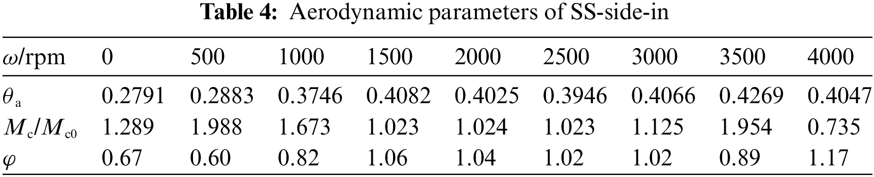
It is evident that coolant consumption rises steeply with the growing rotating speed. When the stagnation line (SL) is positioned near RowP, coolant consumption is considerably lower at 1500 and 3000 rpm. The SS-side-in shows superior cooling performance to the PS-side-in under the relatively high rotating speed. These findings hold true for the cooling structure examined in this study.
Our goal is to examine how rotational effects impact the characteristics of the composite conjugate cooling. Given that various sorts of gas turbines have their own designated rotating speeds, it is important to conduct more thorough simulations within specific ranges of rotating speeds while designing the blade leading edge (BLE) cooling conceptions such as the vortex and film composite cooling (VFCC) structures for various gas turbine applications (air, sea, land).
In this study, the impacts of rotation and the coolant injecting nozzle position on the characteristics of the vortex and film composite conjugate cooling are explored under the mainstream flow (MF) within practical cases. The governing equations solved in the numerical simulations are the three-dimensional steady RANS coupled with SST~γ-θ. Additionally, incorporating the blade material solid region into the internal cooling structure brings about fluid-thermal coupling. By comparing coolant injecting nozzles placed near the pressure surface side (PS-side-in) vs. the suction surface side (SS-side-in), we can analyze how external film cooling (EFC) flow interacts with internal vortex cooling (IVC) flow, and how rotation affects IVC flow. We also define the dimensionless temperature θ for analysis, which varies inversely with temperature.
In terms of the MF, the position of the stagnation line (SL) is the main factor brought about by the rotation. When the position of the SL aligns with the film holes, coolant jet that flows from the film holes is suppressed effectively onto the blade surface, providing extensive coverage and resulting in a lower temperature distribution on the blade surface. On the other hand, when the SL remains in other positions, the coolant film lifts off from the blade surface, leading to a higher blade surface temperature. However, the impact of nozzle position on coolant film attachment is not easily discernible.
For the IVC the centrifugal force as a result of the rotation makes the coolant move axially. The axial velocity and the angular velocity bring about the Coriolis force. The direction of the Coriolis force is opposite and similar to the near-wall vortex flow direction in the PS-side-in and SS-side-in, respectively. This makes the internal heat transfer intensity in SS-side-in case higher than that in PS-side-in under high rotating speed, leading to a lower temperature of the blade surface in SS-side-in with the heat conduction brought about by the blade material. The blade surface area-averaged dimensionless temperature that is inversely proportional to the actual temperature is 7.8% higher in SS-side-in as compared to that in PS-side-in.
For the evaluation of the vortex and film composite cooling performance, a flexible criterion (composite cooling parameter) comprehensively considering both the blade surface temperature as well as the coolant consumption is utilized to quantitatively compare the composite cooling performance under various conditions. As the rotational speed is higher or equal to 3000 rpm, SS-side-in structure presents a relatively lower blade surface temperature and lower coolant consumption. The composite cooling parameter of SS-side-in structure is 18.6%–64.8% higher than that of PS-side-in structure.
For practical recommendations, first, the nozzles arranged near the suction surface side is suggested to the relatively high rotational speed conditions. Second, the row of film holes should be arranged to the SL position at the working rotating speed to improve the cooling performance. Third, the cross-section of the internal vortex cooling chamber could gradually increase from the hub to the shroud, which would prevent the vortex cooling intensity near the hub region from decreasing under the influence of the centrifugal force at a relatively high rotational speed.
There are some recommendations for future work to build upon the current study. As for the vortex and film composite cooling, the fan-shaped film hole, the variable cross-section vortex chamber and other structures could be introduced into the composite cooling for further study. As for the asymmetrical property, the effects of the asymmetrical property on the performance of the cooling conceptions stay in the mid-chord, or the trailing edge region could be deeply investigated under rotational conditions. In addition, the effects of the rotor-stator interaction on the vortex and film composite cooling should also be researched in detail. As for the exponent n in the cooling performance parameter, investigations on finding the optimized value of n to achieve the optimized value of the cooling performance parameter are also recommended. Such investigations are also important in studying the properties of the composite cooling performance, not limited to the vortex and film composite cooling.
Acknowledgement: Not applicable.
Funding Statement: This work was supported by the National Science and Technology Major Project under Grant (2017-I-0009-0010). Received by Liang Li. https://en.most.gov.cn/.
Author Contributions: The authors confirm their contribution to the paper as follows: conceived and designed the analysis, collected the data, performed the analysis, and wrote the paper: Jiefeng Wang; conceived and designed the analysis, revised the article: Eddie Yin Kwee Ng. Liang Li; collected data: Jianwu Li, Yanhao Cao, Yanan Huang. All authors reviewed the results and approved the final version of the manuscript.
Availability of Data and Materials: There is no unavailable data in this study.
Conflicts of Interest: The authors declare that they have no conflicts of interest to report regarding the present study.
References
1. Han, J. C., Dutta, S., Ekkad, S. (2012). Gas turbine heat transfer and cooling technology. Boca Raton: Taylor & Francis. [Google Scholar]
2. Kreith, F., Sonju, O. (1965). The decay of a turbulent swirl in a pipe. Journal of Fluid Mechanics, 22(2), 257–271. [Google Scholar]
3. Ling, J. P., Ireland, P. T., Harvey, N. W. (2006). Measurement of heat transfer coefficient distributions and flow field in a model of a turbine blade cooling passage with tangential injection. Proceedings of the ASME Turbo Expo 2006: Power for Land, Sea, and Air, Barcelona, Spain. [Google Scholar]
4. Liu, Z., Li, J., Feng, Z. (2013). Numerical study on the effect of jet slot height on flow and heat transfer of swirl cooling in leading edge model for gas turbine blade. In: Turbo expo: Power for land, sea, and air. San Antonio, Texas, USA, American Society of Mechanical Engineers. [Google Scholar]
5. Liu, Z., Li, J., Feng, Z. (2015). Numerical study of swirl cooling in a turbine blade leading-edge model. Journal of Thermophysics and Heat Transfer, 29(1), 166–178. [Google Scholar]
6. Liu, Z., Li, J., Feng, Z., Simon, T. (2015). Numerical study on the effect of jet nozzle aspect ratio and jet angle on swirl cooling in a model of a turbine blade leading edge cooling passage. International Journal of Heat and Mass Transfer, 90, 986–1000. [Google Scholar]
7. Fan, X., Li, L., Zou, J., Wang, J., Wu, F. (2018). Local heat transfer of vortex cooling with multiple tangential nozzles in a gas turbine blade leading edge cooling passage. International Journal of Heat and Mass Transfer, 126, 377–389. [Google Scholar]
8. Mousavi, S. M., Ghadimi, B., Kowsary, F. (2018). Numerical study on the effects of multiple inlet slot configurations on swirl cooling of a gas turbine blade leading edge. International Communications in Heat and Mass Transfer, 90, 34–43. [Google Scholar]
9. Biegger, C., Sotgiu, C., Weigand, B. (2015). Numerical investigation of flow and heat transfer in a swirl tube. International Journal of Thermal Sciences, 96, 319–330. [Google Scholar]
10. Biegger, C., Weigand, B. (2015). Flow and heat transfer measurements in a swirl chamber with different outlet geometries. Experiments in Fluids, 56(4), 78. [Google Scholar]
11. Kusterer, K., Lin, G., Sugimoto, T., Bohn, D., Tanaka, R. et al. (2015). Novel gas turbine blade leading edge cooling configuration using advanced double swirl chambers. Proceedings of the ASME Turbo Expo 2015: Turbine Technical Conference and Exposition, Montreal, Quebec, Canada. [Google Scholar]
12. Lin, G., Kusterer, K., Bohn, D., Sugimoto, T., Tanaka, R. et al. (2013). Heat transfer and pressure loss characteristics of double swirl chambers cooling with different inlet and outlet configurations. Proceedings of the International Conference on Power Engineering, Wuhan, China. [Google Scholar]
13. Lin, G., Kusterer, K., Bohn, D., Sugimoto, T., Tanaka, R. et al. (2013). Investigation on heat transfer enhancement and pressure loss of double swirl chambers cooling. Propulsion and Power Research, 2(3), 177–187. [Google Scholar]
14. Liu, Y., Rao, Y., Weigand, B. (2019). Heat transfer and pressure loss characteristics in a swirl cooling tube with dimples on the tube inner surface. International Journal of Heat and Mass Transfer, 128, 54–65. [Google Scholar]
15. Zhao, H. J., Jiang, Y. T., Zheng, Q., Chen, Y., Lu, S. (2021). Particle deposition characteristics of U-shaped RIB channel of marine gas turbine. Tuijin Jishu/Journal of Propulsion Technology, 42(8), 1906–1914. [Google Scholar]
16. Zhu, X. D., Zhang, J. Z., Tan, X. M. (2019). Numerical assessment of round-to-slot film cooling performances on a turbine blade under engine representative conditions. International Communications in Heat and Mass Transfer, 100, 98–110. [Google Scholar]
17. Ye, L., Liu, C., Du, K., Chen, L., Wang, Y. et al. (2022). Influences of groove configuration and density ratio on grooved leading-edge showerhead film cooling using the pressure sensitive paint measurement technique. International Journal of Heat and Mass Transfer, 190, 122641. [Google Scholar]
18. Ye, L., Liu, C., Li, B., Zhu, A. D. (2022). Detailed showerhead cooling effectiveness measurements on the notched leading-edge surface: Effect of freestream turbulence and density ratio. International Communications in Heat and Mass Transfer, 135, 106142. [Google Scholar]
19. Fan, X., Du, C., Li, L., Li, S. (2016). Numerical simulation on effects of film hole geometry and mass flow on vortex cooling behavior for gas turbine blade leading edge. Applied Thermal Engineering, 112, 472–483. [Google Scholar]
20. Du, C., Li, L., Fan, X., Feng, Z. P. (2017). Rotational influences on aerodynamic and heat transfer behavior of gas turbine blade vortex cooling with bleed holes. Applied Thermal Engineering, 121, 302–313. [Google Scholar]
21. Li, L., Du, C. H., Chen, X. X., Wang, J. F., Fan, X. J. (2018). Numerical study on flow and heat transfer behavior of vortex and film composite cooling. Journal of Mechanical Science and Technology, 32(6), 2905–2917. [Google Scholar]
22. Zhang, M., Wang, N., Han, J. C. (2019). Internal heat transfer of film-cooled leading edge model with normal and tangential impinging jets. International Journal of Heat and Mass Transfer, 139, 193–204. [Google Scholar]
23. Wang, J., Li, L., Li, J. W., Wu, F., Du, C. H. (2021). Numerical investigation on flow and heat transfer characteristics of vortex cooling in an actual film-cooled leading edge. Applied Thermal Engineering, 185, 115942. [Google Scholar]
24. Timko, L. (1984). Energy efficient engine high pressure turbine component test performance report. NASA-CR-168289. https://ntrs.nasa.gov/citations/19900019237 (accessed on 15/08/2023) [Google Scholar]
25. Celik, I. B., Ghia, U., Roache, P. J., Freitas, C., Coloman, H. et al. (2008). Procedure for estimation and reporting of uncertainty due to discretization in CFD applications. Journal of Fluids Engineering-Transactions of the ASME, 130(7), 078001. [Google Scholar]
26. Kohli, A., Bogard, D. (1997). Adiabatic effectiveness, thermal fields, and velocity fields for film cooling with large angle injection. Journal of Turbomachinery, 119(2), 352–358. [Google Scholar]
27. Safi, A., Hamdan, M. O., Elnajjar, E. (2020). Numerical investigation on the effect of rotation on impingement cooling of the gas turbine leading edge. Alexandria Engineering Journal, 59(5), 3781–3797. [Google Scholar]
28. Fan, X. J., He, C. X., Gan, L., Li, L., Du, C. H. (2020). Experimental study of swirling flow characteristics in a semi cylinder vortex cooling configuration. Experimental Thermal and Fluid Science, 113, 110036. [Google Scholar]
29. Shevchuk, I. V., Jenkins, S. C., Weigand, B., Wolfersdorf, J., Neumann, O. et al. (2011). Validation and analysis of numerical results for a varying aspect ratio two-pass internal cooling channel. Journal of Heat Transfer, 133(5), 1085–1094. [Google Scholar]
30. Wang, J., Li, J., Zhao, Y., Li, J., Li, R. et al. (2023). Numerical investigation on conjugate heat transfer characteristics of film and vortex composite cooling under rotating conditions. Proceedings of the Institution of Mechanical Engineers, Part A: Journal of Power and Energy. https://doi.org/10.1177/09576509231182227 [Google Scholar] [CrossRef]
Cite This Article
 Copyright © 2023 The Author(s). Published by Tech Science Press.
This work is licensed under a Creative Commons Attribution 4.0 International License , which permits unrestricted use, distribution, and reproduction in any medium, provided the original work is properly cited.
 Downloads
 Citation Tools