
 Submit a Paper
 Propose a Special lssue
 Open Access
ARTICLE

A Sensor-less Surface Mounted PMSM for Electronic Speed Control in Multilevel Inverter
1 Karthikeya Polytechnic College, Manapparai, Tamil Nadu, 621306, India
2 Department of Electrical and Electronics Engineering, Sona College of Technology, Salem, Tamil Nadu, 636005, India
* Corresponding Author: S. Dinesh Kumar. Email:
Intelligent Automation & Soft Computing 2023, 36(2), 2201-2215. https://doi.org/10.32604/iasc.2023.027467
Received 18 January 2022; Accepted 27 March 2022; Issue published 05 January 2023
 View Full Text
 Download PDF
Abstract
Recent advancements in power electronics technology evolves inverter fed electric motors. Speed signals and rotor position are essential for controlling an electric motor accurately. In this paper, the sensorless speed control of surface-mounted permanent magnet synchronous motor (SPMSM) has been attempted. SPMSM wants a digital inverter for its precise working. Hence, this study incorporates fifteen level inverter to the SPMSM. A sliding mode observer (SMO) based sensorless speed control scheme is projected to determine rotor spot and speed of the multilevel inverter (MLI) fed SPMSM. MLI has been operated using a multi carrier pulse width modulation (MCPWM) strategy for generation of fifteen level voltages. The simulation works are executed with MATLAB/SIMULINK software. The steadiness and the heftiness of the projected model have been investigated under no loaded and loaded situations of SPMSM. Furthermore, the projected method can be adapted for electric vehicles.Keywords
PMSM has been used broadly because of its advantageous features such as better power density, good torque ratio, worthy efficacy, minimum loss and compact [1,2]. By the placement of the permanent magnet on the rotor, PMSM has been classified into two categories such as SPMSM and interior PMSM (IPMSM). SPMSM has identical direct and quadrature axis inductances; on the other hand, IPMSM partakes the uneven direct and quadrature axis inductances. So as to achieve precise control of SPMSM, the data of rotor spot and speed have been required. Conventionally mechanical sensors were employed to find the rotor spot and speed. They have several disadvantages such as high cost, increased size, decreased reliability and minimized applications [3]. To overwhelm those drawbacks, the sensorless control scheme for PMSM has been proposed [4,5]. Then various control schemes for instance space vector control [6], direct torque control [7], model reference adaptive system (MRAS) [8] have been presented. The vector control system is accurate, dynamic and has extensive limit of speed and spot control. Continually, the intelligent technique namely neural network (NN) has been proposed to design the speed controller for PMSM [9]. It has the merits of quick convergence rate, great exactness and robust.
Recently, various sensorless control and state estimation techniques have been projected [10–12]. Among them SMO and MRAS based sensorless control strategies have been utilized more. Because, they can be implemented easily in the digital systems and has the merits of simplicity and rapid control. A fuzzy based controller scheme has been proposed to replace the Proportional–Integral–Derivative (PID) controller in MRAS [13]. An adaptive line enhancer along with SMO scheme has been introduced to increase the reference ideal for the speed auto-sensing of an IPMSM [14]. An advanced SMO scheme has been presented to control speed in a fuzzy controlled wind energy conversion system [15]. The stability investigation of sensorless speed control strategy for PMSM using MRAS has been performed [16]. To minimize the opposing influence of stricture disparity in sensorless speed control of a PMSM, the multiple stricture assessment by means of MRAS has been presented [17]. The modelling and simulation of a novel brain emotional learning and fuzzy-based intelligent controller (BELFBIC) for 3 phase induction motor V/f speed control was proposed [18], and it has been tested [19,20]. Lately, the authors have carried out a study on a sensorless T-source inverter-based PMSM drive incorporating the PI controller along with a technique to handle the time-altering strictures [21]. This study intends a sensorless speed control scheme using SMO for a SPMSM. It intends to legalize the rotor speed according to the change in load torque. In Section 2, the exact prototypical of MLI fed SPMSM has been presented. Section 3 discusses the SMO based sensorless control scheme to evaluate the rotor position and the speed. Section 4 provides the simulation results and Section 5 accomplishes the study.
The structure of a SPMSM has been demonstrated in Fig. 1. In a SPMSM, Ld = Lq = L. Thus in the two-phase revolving d-q direct, the voltage equations of SPMSM have been provided.
where
id, iq current in d and q axis
ud, uq voltage in d and q axis
L inductance
R resistance
ψf magnetic flux
ω rotor speed
p no. of pole pairs
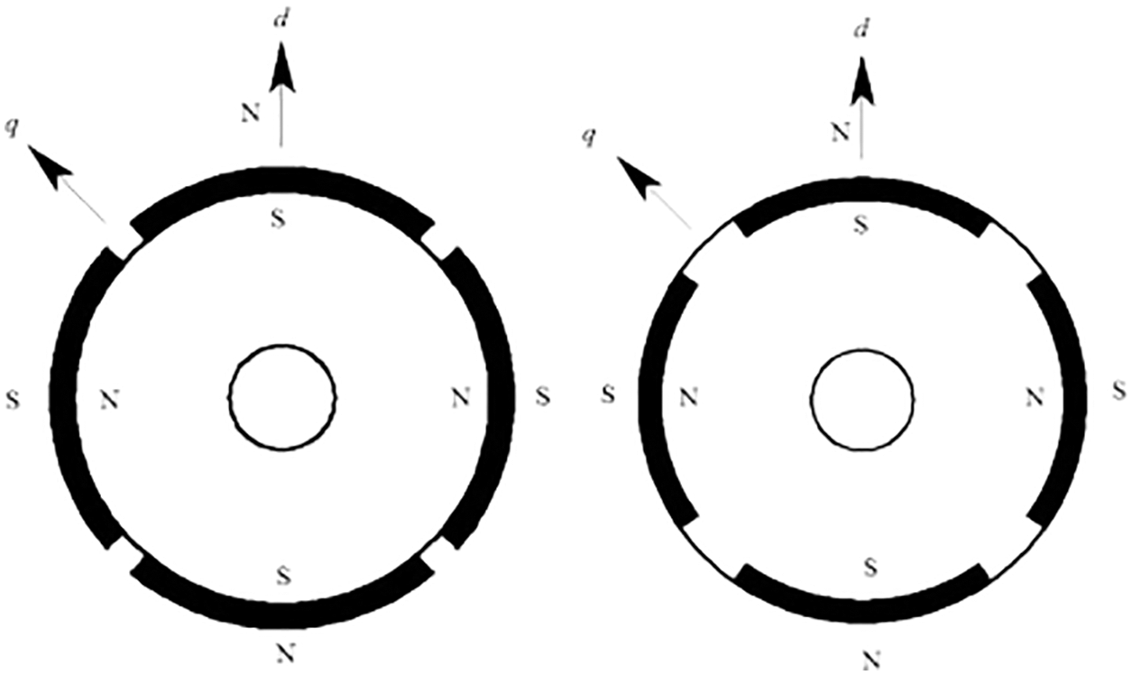
Figure 1: Assembly of SPMSM
The machine-driven movement of SPMSM can be expressed from Eqs. (3) and (4).
where
θ rotor spot
J moment of inertia
T motor torque
F viscous friction constant
TLload torque
The vector control scheme controls the motor current using stator current vector and magnetic field coordination standard. Consequently, the motor torque has been controlled. In SPMSM, the vector control system id = 0.
The torque equation of SPMSM has been expressed in Eq. (5).
Torque T is directly proportional to the current iq. For controlling the torque, the current iq has to be altered. The adaptation association amid the 2 phase revolving d − q direct system and 2 phase stationary α − β direct system has been illustrated in Fig. 2.
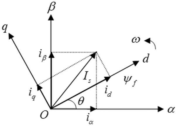
Figure 2: Conversion illustration amid the 2 coordinate system
The Park’s converse conversion has been presented to convert the d-q mount that revolves beside the untrue excitation vector if absorbed as the d axis into the static stator α − β mount.
The modelling of SPMSM in the 2 phase fixed α − β orientation mount have been expressed as
where
iα, iβ current for individual phase
uα, uβ voltage for individual phase
eα, eβ back EMF for individual phase
L inductance
R resistance
ψf magnetic flux
ω rotor speed
θ rotor position
The structure of SMO based sensorless speed control for MLI fed SPMSM has been displayed in Fig. 3.
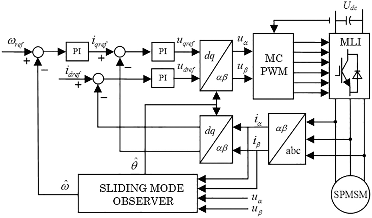
Figure 3: Illustration of SMO based sensorless speed control scheme for MLI fed SPMSM
MLI have an organization of power switching devices and capacitor voltage sources. MLI are apt for high-voltage applications due to their capability to produce output voltage waveforms with an improved harmonic band and get greater voltages with a minimum device ranking. MLI have the capability to satisfy the growing demand of power rating and power quality. The circuit diagram of the 1 phase 15-level MLI is exposed in Fig. 4.
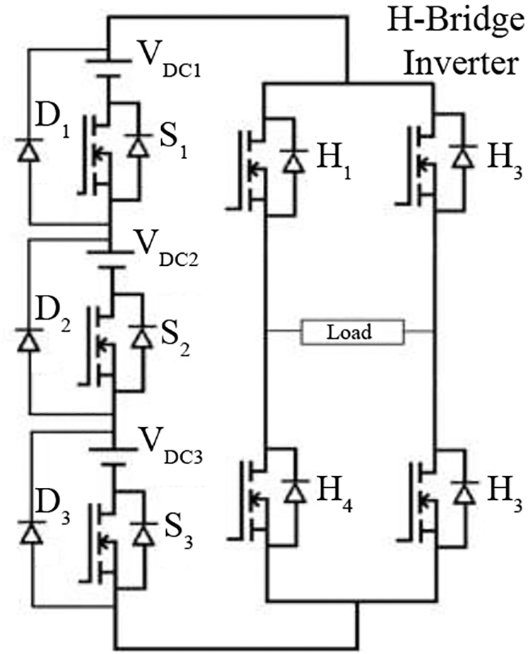
Figure 4: Circuit diagram of the single phase 15-level MLI
The 1-phase 15-level inverter has been established from the 7-level inverter. It involves a 1-phase traditional H-bridge inverter, 3 switches, and 3 voltage sources. The H-bridge methodology has the advantages such as minimized count of switches, diodes for inverters of the similar count of levels. Appropriate switching of MLI can generate 15 output voltage levels such as Vdc, 6 Vdc/7, 5 Vdc/7, 4 Vdc/7, 3 Vdc/7, 2 Vdc/7, Vdc/7,0, −Vdc/7, −2 Vdc/7, −3 Vdc/7, −4 Vdc/7, −5 Vdc/7, −6Vdc/7, −Vdc from the dc supply voltage. In this paper, multi carrier pulse width modulation (MCPWM) method has been employed to create the fifteen level output voltage as shown in Fig. 5.
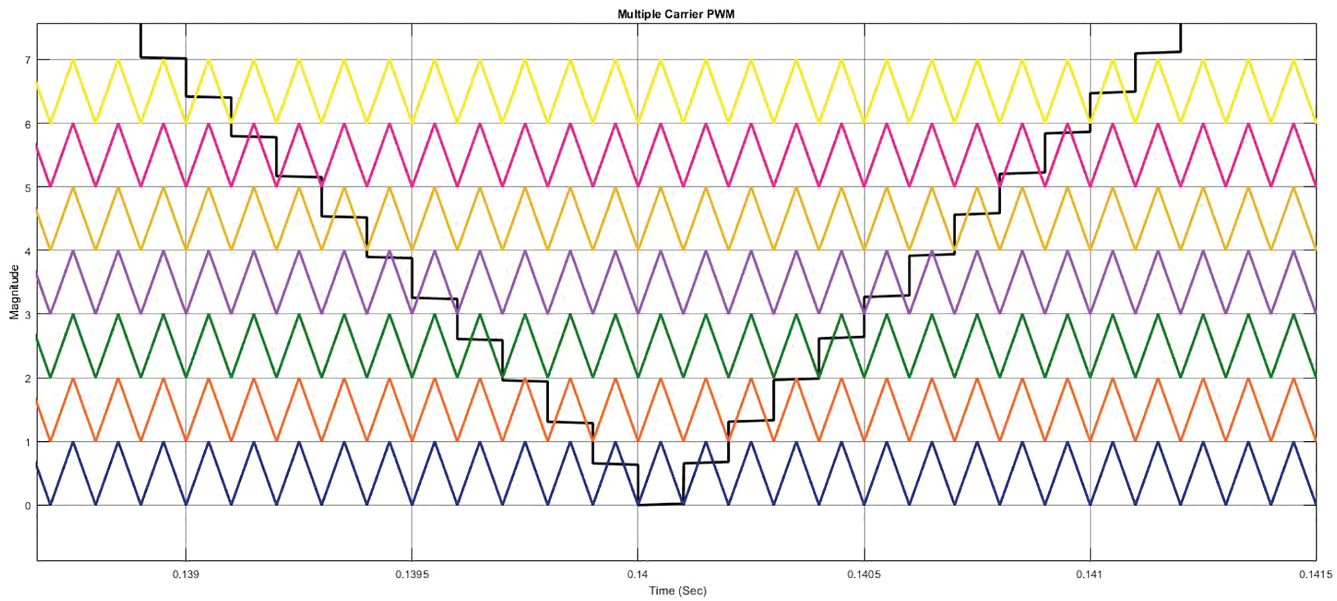
Figure 5: Waveform of MCPWM
Seven equivalent heft carrier triangular signals with compensation is likened with the sinusoidal reference pulse. They have been applied to the switches S1, S2, S3. After these 2 sinusoidal pulses with 180° shift have been likened with the carrier triangular pulse. These PWM pulses consists of dead band and it will evade the discharge over issue amid two components. These PWM signals have been applied to the 1-phase inverter circuit switches H1, H2, H3, and H4. It has been experienced that the controlling of DC buses is simple while using MLI. Fig. 6 demonstrates the switching patterns of PV system based 15-level single phase MLI output voltage.
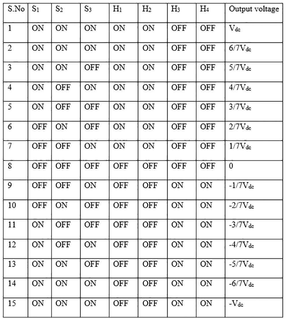
Figure 6: Switching pattern for 15-level 7-switch topology
In the α − β coordination, the electrical equation of SPMSM can be expressed as follows.
where eα, eβ are the electrical motive force.
The dynamic error equations of SPMSM can be given as follows.
where
The sliding mode has been defined as
On the sliding mode,
The Lyapunov function has been characterized as
The substitution of Eqs. (29) and (30) into (31) offers
The rotor position and speed have been assessed as
where
The specifications of SPMSM for simulation are provided in Tab. 1. The MATLAB simulink model is exemplified in Fig. 7.
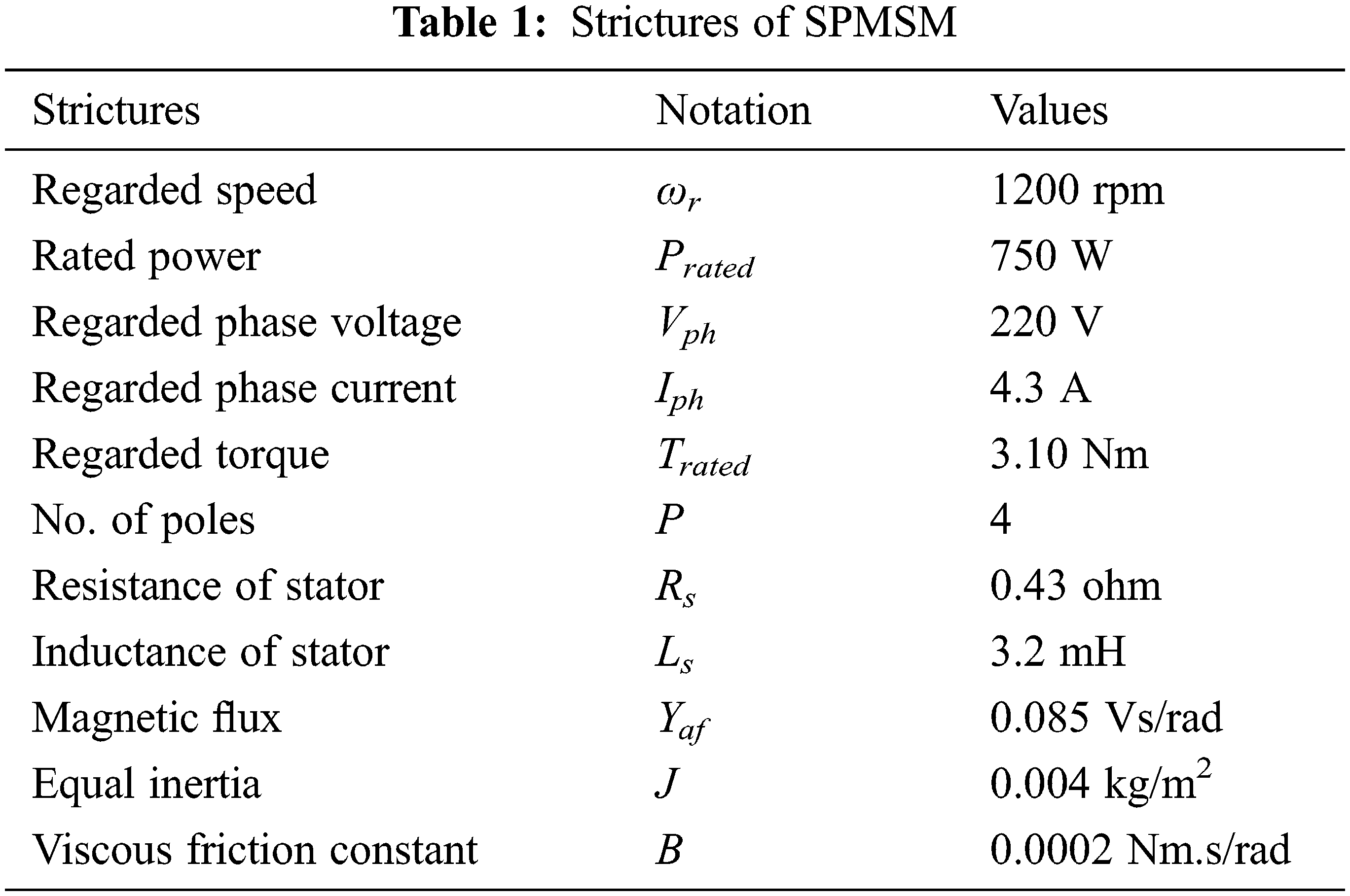
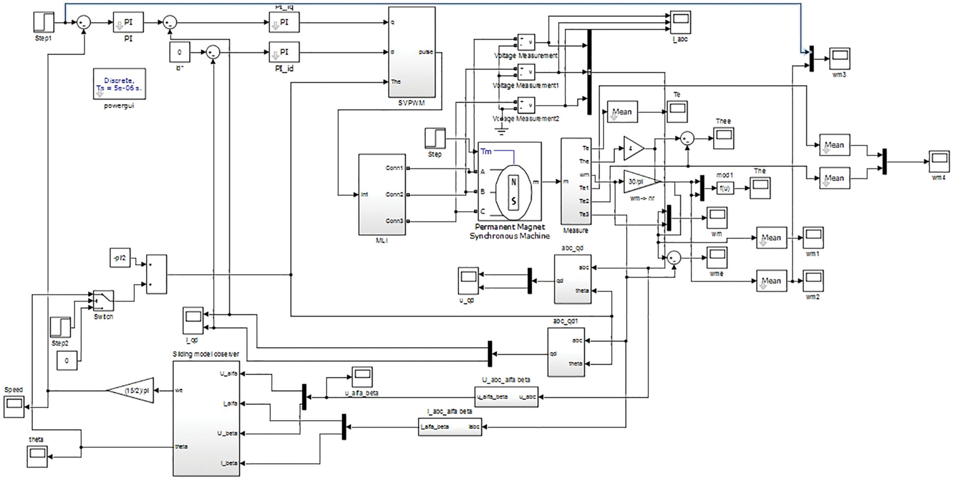
Figure 7: Simulink prototype of the projected system
The results have been attained for 2 dissimilar situations for instance no load and loaded settings with the established model. In both conditions, the simulation is executed for four dissimilar reference speeds for instance 670, 800, 750, 1000 and 1500 rpm.
Here the load has not been connected. The simulation outcomes are extracted for 4 dissimilar reference speeds. Fig. 8 demonstrates the speed waveform along with reference and output speed signs for 670, 800, 1000 and 1500 rpm respectively. Correspondingly, the torque waveform attained for the aforesaid speeds has been exposed in Fig. 9.
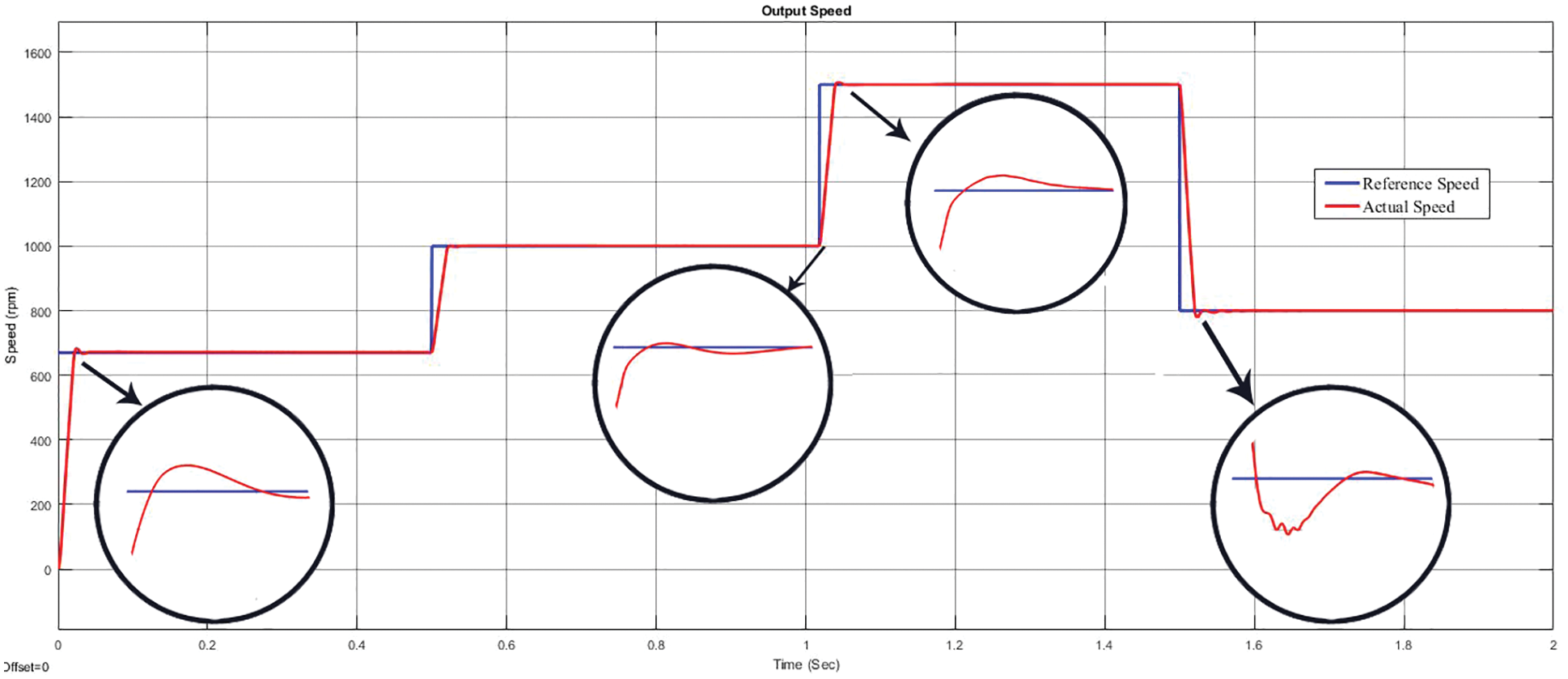
Figure 8: Output speed waveform with reference and actual speeds under no loaded condition
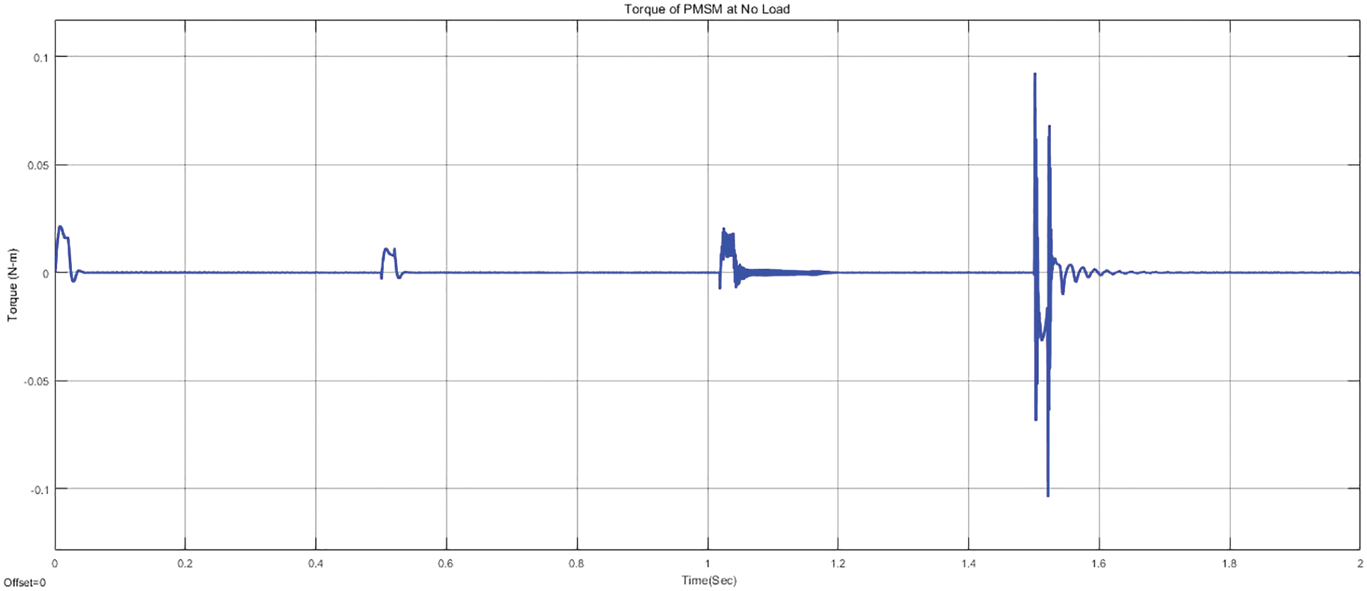
Figure 9: Output torque waveform under no loaded condition
From the Figs. 8 and 9, it has been identified that, the speed of the SPMSM slow down down at 0.05 s for least speeds, while the identical at 0.1 s for high speeds with a minor primal perturbation. The output speeds of the SPMSM evidently portrays that, it has not noticeable fluctuations that is vastly favored for several perpetual appliances. For no load situation, the torque will be 0 Nm. At the speed of 0 rpm, the torque will be 0 Nm. Conversely, at higher speeds the torque has specific primal fluctuations and slow down to 0 Nm finally. The fluctuations are at the bound of 0.02, 0.02, 0.03 and 0.09 Nm for the speed ranges 670, 800, 1000 and 1500 rpm respectively. The current waveform of d and q axis has been illustrated in Fig. 10. Similarly, the stator current waveform under no loaded condition has been shown in Fig. 11.
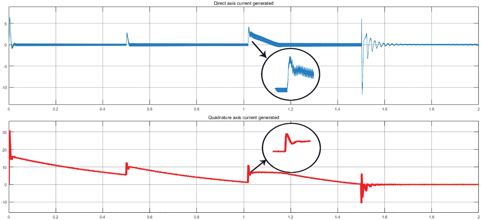
Figure 10: Current waveform of d and q axis under no loaded condition
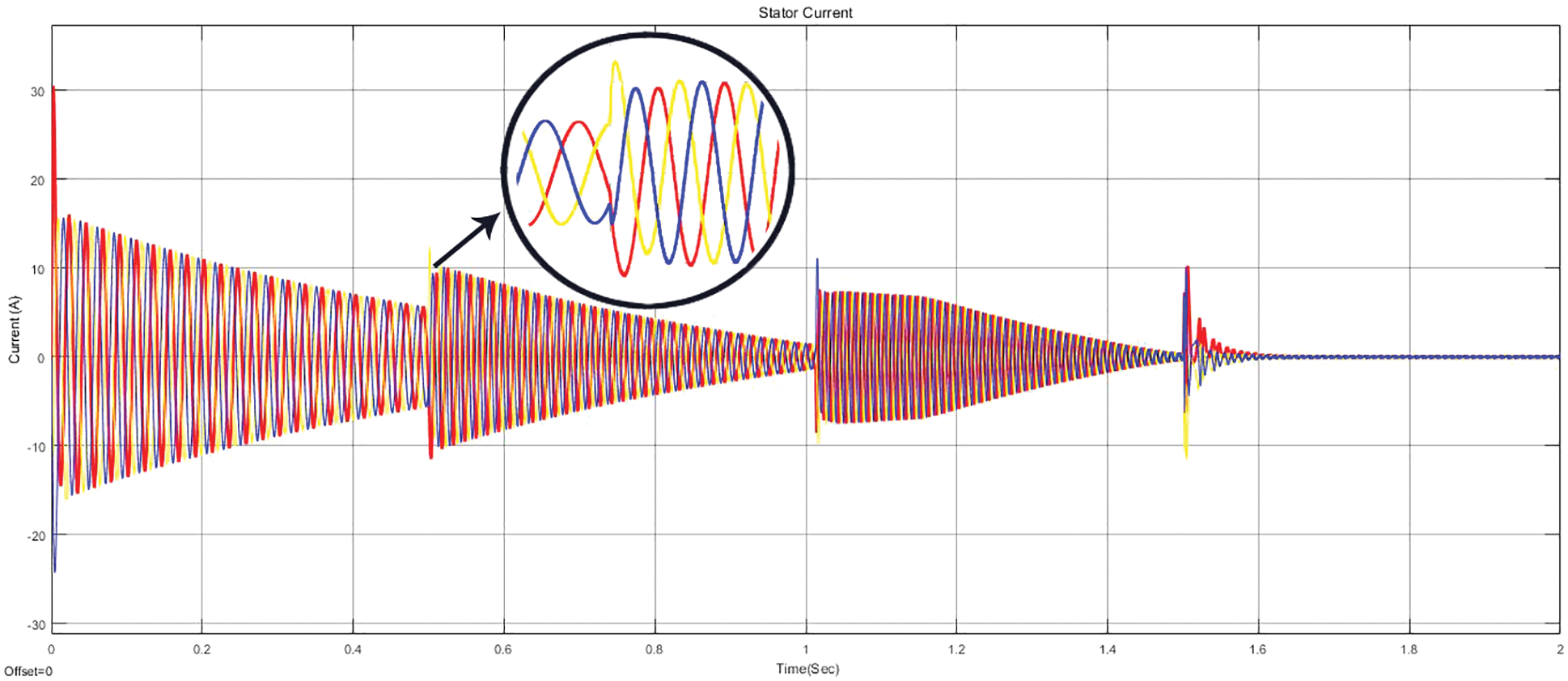
Figure 11: Stator current waveform under no loaded condition
In this case, a load of 3 Nm has been connected at the running condition during 0.4 and 1.5 s. A minor deviance amid the reference and output speed has been occurred. The speed response waveforms have been illustrated in Fig. 12. The respective torque waveform has been shown in Fig. 13. The current waveform of d and q axis under loaded condition has been illustrated in Fig. 14. Similarly, the stator current waveform under loaded condition has been shown in Fig. 15.
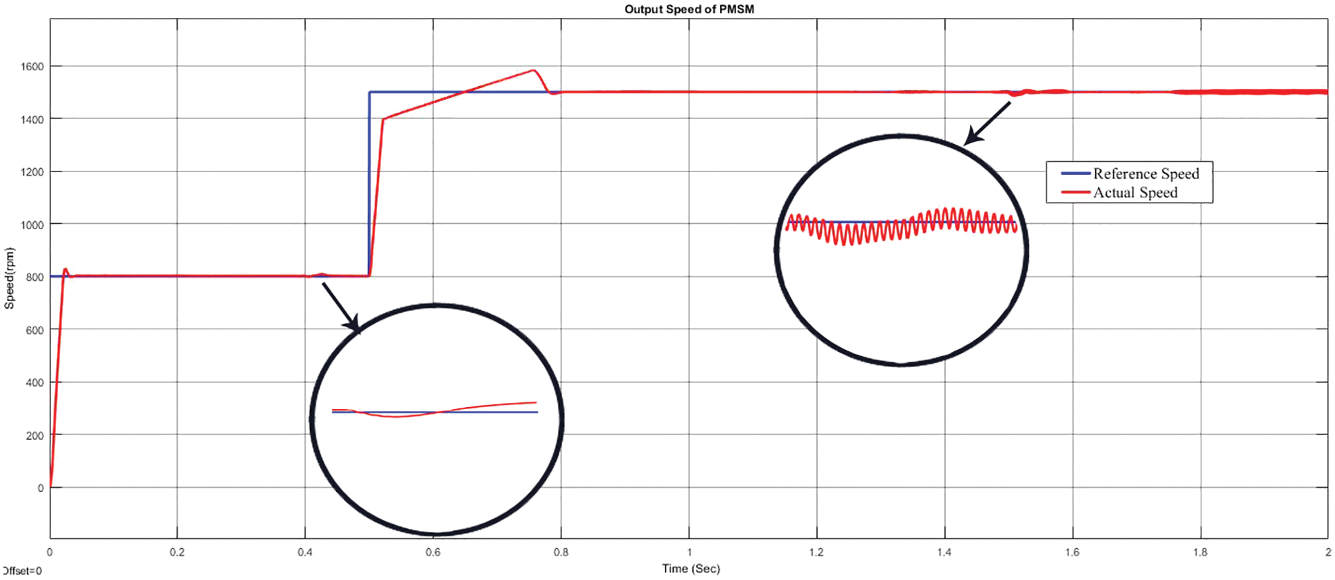
Figure 12: Output speed waveform under loaded condition
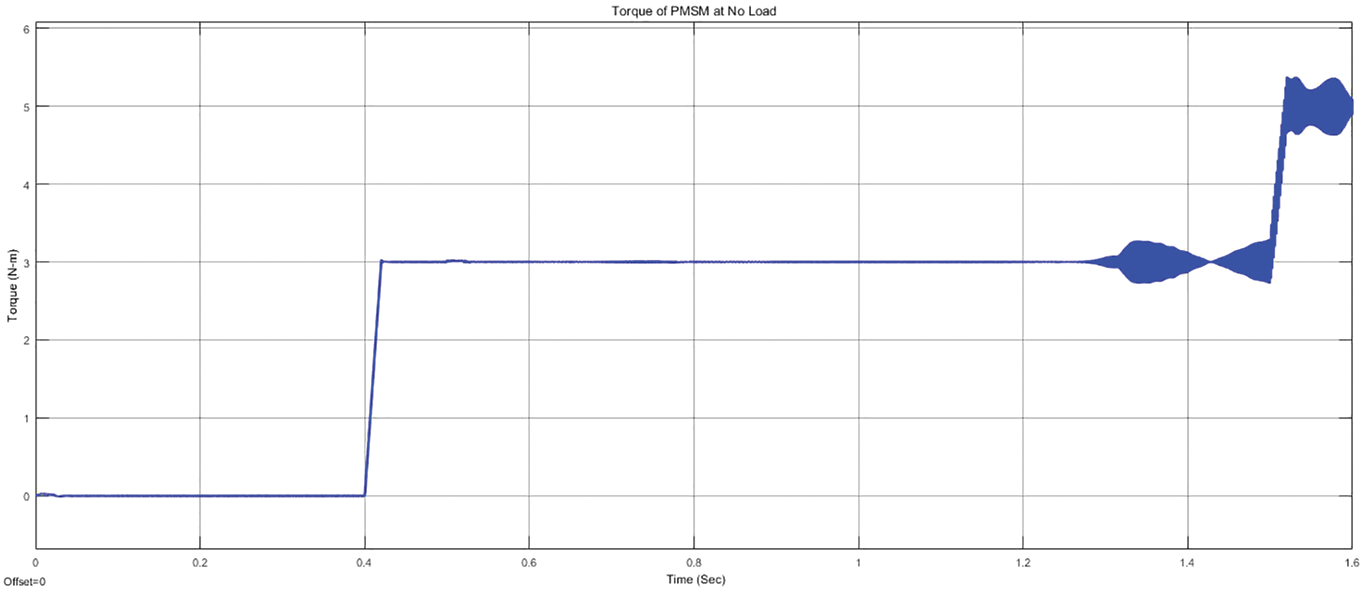
Figure 13: Torque waveform under loaded condition
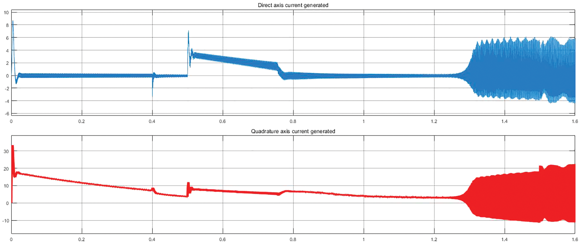
Figure 14: Current waveform of d and q axis under loaded condition
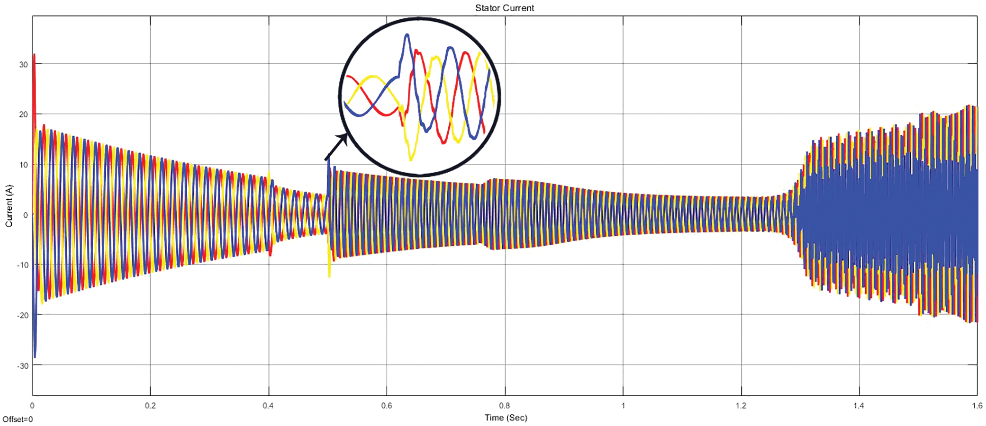
Figure 15: Stator current waveform of SPMSM under loaded condition
The advantage of the proposed method is albeit at loaded situation, the anticipated output speed has been attained without any significant fluctuations. Likewise, the torque waveform has no ripple content, thus the efficacy of SPMSM has been improved. It results with the noiseless operation of SPMSM.
A sensorless speed control using SMO for a SPMSM fed by fifteen level inverter has been proposed in this study. MLI has been activated using MCPWM strategy for producing fifteen level voltages. SMO has been modeled for assessing the speed and the rotor position. The projected system is modeled by means of MATLAB/SIMULINK software and has been tested for substantial robustness. The simulations have been carried out for two cases such as no loaded and loaded condition. The results have been extracted under four different speeds. The speed and torque waveforms have been plotted and analyzed. The outcomes evident the efficacy of the projected SMO based sensorless speed organizer. Furthermore, the projected scheme is effective and vigorous against the external disruptions. Concerning the practical evaluation, the working of the controller accompanied by the various observers is under development and its completion is forthcoming.
Acknowledgement: The authors with a deep sense of gratitude would thank the supervisor for his guidance and constant support rendered during this research.
Funding Statement: The authors received no specific funding for this study.
Conflicts of Interest: The authors declare that they have no conflicts of interest to report regarding the present study.
References
1. F. Genduso, R. Miceli, C. Rando and G. R. Galluzzo, “Back EMF sensorless-control algorithm for high-dynamic performance PMSM,” IEEE Transactions on Industrial Electronics, vol. 57, no. 6, pp. 2092–2100, 2010. [Google Scholar]
2. V. Kumar, P. Gaur and A. P. Mittal, “ANN based self tuned PID like adaptive controller design for high performance PMSM position control,” Expert Systems with Applications, vol. 41, no. 17, pp. 7995–8002, 2014. [Google Scholar]
3. M. Pacas, “Sensorless drives in industrial applications,” IEEE Industrial Electronics Magazine, vol. 5, no. 2, pp. 16–23, 2011. [Google Scholar]
4. A. Accetta, M. Cirrincione, M. Pucci and G. Vitale, “Sensorless control of PMSM fractional horsepower drives by signal injection and neural adaptive-band filtering,” IEEE Transactions on Industrial Electronics, vol. 59, no. 3, pp. 1355–1366, 2012. [Google Scholar]
5. T. O. Kowalska, M. Dybkowski and K. Szabat, “Adaptive Sliding-mode neuro-fuzzy control of the two-mass induction motor drive without mechanical sensors,” IEEE Transactions on Industrial Electronics, vol. 57, no. 2, pp. 553–564, 2010. [Google Scholar]
6. M. Rho and S. Kim, “Development of robust starting system using sensorless vector drive for a microturbine,” IEEE Transactions on Industrial Electronics, vol. 57, no. 3, pp. 1063–1073, 2010. [Google Scholar]
7. J. Beerten, J. Verveckken and J. Driesen, “Predictive direct torque control for flux and torque ripple reduction,” IEEE Transactions on Industrial Electronics, vol. 57, no. 1, pp. 404–412, 2010. [Google Scholar]
8. T. O. Kowalska and M. Dybkowski, “Stator-current-based mras estimator for a wide range speed-sensorless induction-motor drive,” IEEE Transactions on Industrial Electronics, vol. 57, no. 4, pp. 1296–1308, 2010. [Google Scholar]
9. Z. Wang, Y. Zhang and H. Fang, “Neural adaptive control for a class of nonlinear systems with unknown deadzone,” Neural Computing and Applications, vol. 17, no. 4, pp. 339–345, 2008. [Google Scholar]
10. C. Lv, Y. Liu, X. Hu, H. Guo, D. Cao et al., “Simultaneous observation of hybrid states for cyber-physical systems: A case study of electric vehicle powertrain,” IEEE Transactions on Cybernetics, vol. 48, no. 8, pp. 2357–2367, 2018. [Google Scholar]
11. C. Lv, Y. Xing, J. Zhang, X. Na, Y. Li et al., “Levenberg-marquardt backpropagation training of multilayer neural networks for state estimation of a safety-critical cyber-physical system,” IEEE Transactions on Industrial Informatics, vol. 14, no. 8, pp. 3436–3446, 2018. [Google Scholar]
12. Y. Xing, C. Lv, H. Wang, D. Cao, E. Velenis et al., “Driver activity recognition for intelligent vehicles: A deep learning approach,” IEEE Transactions on Vehicular Technology, vol. 68, no. 6, pp. 5379–5390, 2019. [Google Scholar]
13. Y. Mei, K. Sun and Y. Shi, “A 2-D fuzzy logic based MRAS scheme for sensorless control of interior permanent magnet synchronous motor drives with cyclic fluctuating loads,” Chinese Journal of Electrical Engineering, vol. 1, no. 1, pp. 85–91, 2015. [Google Scholar]
14. Y. Zhao, W. Qiao and L. Wu, “Improved rotor position and speed estimators for sensorless control of interior permanent-magnet synchronous machines,” IEEE Journal of Emerging and Selected Topics in Power Electronics, vol. 2, no. 3, pp. 627–639, 2014. [Google Scholar]
15. J. Yan, H. Lin, Y. Feng, X. Guo, Y. Huang et al., “Improved sliding mode model reference adaptive system speed observer for fuzzy control of direct-drive permanent magnet synchronous generator wind power generation system,” IET Renewable Power Generation, vol. 7, no. 1, pp. 28–35, 2013. [Google Scholar]
16. B. W. Harini, A. Subiantoro and F. Yusivar, “Stability analysis of MRAS speed sensorless control of permanent magnet synchronous motor,” in Proc. Int. Conf. on Sustainable Energy Engineering and Application (ICSEEA), Jakarta, Indonesia, pp. 34–40, 2017. [Google Scholar]
17. O. C. Kivanc and S. B. Ozturk, “Sensorless PMSM drive based on stator feedforward voltage estimation improved with mras multiparameter estimation,” IEEE/ASME Transactions on Mechatronics, vol. 23, no. 3, pp. 1326–1337, 2018. [Google Scholar]
18. A. A. Alsakati, C. A. Vaithilingam, J. Alnasseir and A. Jagadeeshwaran, “Simplex search method driven design for transient stability enhancement in wind energy integrated power system using multi-band PSS4C,” IEEE Access, vol. 9, pp. 83913–83928, 2021. [Google Scholar]
19. A. Jagadeeshwaran, S. Vijayshankar, N. Kannan and C. V. Aravind, “Limited angle BLDC for scan mirror application in space satellite system,” IEEE Aerospace and Electronics Systems Magazine, vol. 31, no. 6, pp. 24–32, 2016. [Google Scholar]
20. A. Jagadeeshwaran, S. Padma, S. Vijay Shankar, V. M. Periyasamy and P. Selvakumar, “Development of limited angle brushless torque motor control drive for scan mirror mechanism,” International Journal of Engineering and Technology, vol. 5, no. 5, pp. 3907–3913, 2014. [Google Scholar]
21. D. Selvam, S. Subbaian, B. Ananthan and T. Rameshkumar, “T-Source Inverter-based sensorless speed control for permanent magnet synchronous motor,” Journal of Testing and Evaluation, vol. 48, no. 2, pp. 1745–1768, 2018. [Google Scholar]
Cite This Article
 Copyright © 2023 The Author(s). Published by Tech Science Press.
This work is licensed under a Creative Commons Attribution 4.0 International License , which permits unrestricted use, distribution, and reproduction in any medium, provided the original work is properly cited.
 Downloads
 Citation Tools