
 Submit a Paper
 Propose a Special lssue
 Open Access
ARTICLE

Improved Harris Hawks Optimization Algorithm Based Data Placement Strategy for Integrated Cloud and Edge Computing
National Institute of Technology Puducherry, Karaikal, 609609, India
* Corresponding Author: V. Nivethitha. Email:
Intelligent Automation & Soft Computing 2023, 37(1), 887-904. https://doi.org/10.32604/iasc.2023.034247
Received 11 July 2022; Accepted 04 February 2023; Issue published 29 April 2023
 View Full Text
 Download PDF
Abstract
Cloud computing is considered to facilitate a more cost-effective way to deploy scientific workflows. The individual tasks of a scientific workflow necessitate a diversified number of large states that are spatially located in different datacenters, thereby resulting in huge delays during data transmission. Edge computing minimizes the delays in data transmission and supports the fixed storage strategy for scientific workflow private datasets. Therefore, this fixed storage strategy creates huge amount of bottleneck in its storage capacity. At this juncture, integrating the merits of cloud computing and edge computing during the process of rationalizing the data placement of scientific workflows and optimizing the energy and time incurred in data transmission across different datacentres remains a challenge. In this paper, Adaptive Cooperative Foraging and Dispersed Foraging Strategies-Improved Harris Hawks Optimization Algorithm (ACF-DFS-HHOA) is proposed for optimizing the energy and data transmission time in the event of placing data for a specific scientific workflow. This ACF-DFS-HHOA considered the factors influencing transmission delay and energy consumption of data centers into account during the process of rationalizing the data placement of scientific workflows. The adaptive cooperative and dispersed foraging strategy is included in HHOA to guide the position updates that improve population diversity and effectively prevent the algorithm from being trapped into local optimality points. The experimental results of ACF-DFS-HHOA confirmed its predominance in minimizing energy and data transmission time incurred during workflow execution.Keywords
In general, scientific applications are considered to be data and computation-intensive as they compose hundreds of correlated tasks [1]. The large datasets and complex structure inherent in a scientific workflow necessitate strict requirements over the capacity of storage in the deployment scenario [2]. However, the scientific workflow implemented in the environment, results in the wastage of more amount of resources. In this context, the cloud computing organizes different virtualized resources available in diversified geographic locations into a pool of resources [3,4]. The potential characteristics of cloud computing such as maximized customizable features, scalability, flexibility and efficiency facilitate a better cost-efficient method for implementing scientific workflows [5]. But, there is a possibility of serious data transmission delays in cloud computing [6]. At this juncture, edge computing resources are generally deployed in very close proximity, which has the feasibility of minimizing the delay in data transmission and introducing more impact on the protection of private datasets [7]. Hence, the merits of cloud computing and edge computing need to be integrated to rationalise the process of data placement associated with a scientific workflow to minimize delays in data transmission in an efficient manner. In the integrated environment, edge computing is specifically responsible for guaranteeing the privacy datasets security for each of the scientific workflow.
In general, Optimization algorithms represent search methods that target determining the solution to an optimization problem. The problem of data placement is an NP-hard optimization problem. The classical data placement strategies contributed to processing scientific workflow mainly utilized evolutionary algorithms [8] to process scientific applications with the process of optimally mapping datasets to data centers. Integrated Genetic algorithm operators and self-adaptive discrete particle swarm optimization algorithm-based data placement policy (GAO-DPSO-DPS) proposed [9] for the data transmission time optimization process incurred in executing workflows. This DPSO scheme inherited the mutation and crossover operations of GA to prevent premature convergence present in the classical PSO algorithm. A differential Evolution-improved DPSO-based data placement strategy was proposed [10] for deriving the merits of edge-cloud computing to achieve better processing of scientific workflows. This DEDPSO-DPS was proposed to handle the process of placing data from the shared datasets into single and multiple workflows situated in geographically varying situations. The Genetic particle swarm optimization (GPSO)-based data placement strategy proposed [11] to utilise the merits of edge and cloud computing that aided in better processing of scientific workflows. This data placement optimized the performance of the model based on the better convergence capability of PSO and exploration capability attributed to the mutation and crossover operations. The simulation experiments of GPSO-DPS conducted using real-world scientific workflow confirmed its superiority in minimizing the data placement costs in an edge-cloud environment.
In this paper, energy and time-driven data placement using Adaptive Cooperative Foraging and Dispersed Foraging Strategies-based HHOA is proposed to reduce the energy utilized during data placement and minimise total data transmission time under the scientific workflow execution.This proposed ACF-DFS-HHOA scheme considered the influential factors of energy consumed by data centers during data placement, delay in data transmission, bandwidth established between dataceneters, the capacity of storage associated with the edge data centers and several edge data centers into account during the event of scientific workflow processing.
2 Problem Definition of ACF-DFS-HHOA-Based Data Placement Strategy
The core objective of this data placement strategy for a specific scientific workflow concentrates on attaining minimum energy utilization and minimum data transmission under the constraints of each datacentre storage capacity and energy threshold of the datacentre.
This problem definition presents an integrated environment that integrates cloud and edge computing, a data placement strategy and a scientific workflow. This integrated environment
where,
Then, the bandwidth between the datacenters of the integrated environment is highlighted in Eqs. (2) and (3)
where,
Then, the energy consumed by the datacenters during the process of data placement is derived from [12] and is represented in Eq. (4)
The proposed model is that energy consumed by a server grows linearly with the increase of its CPU utilization, including the amount of energy spent in the idle state up to the energy consumed when the server is utilized fully. This linear relationship can be represented as shown in the equation where,
The total energy utilized by a dedicated server (
To simulate the performance of the mentioned linear power model, the total energy consumption for edge network servers (
In this integrated environment, a specific scientific workflow
In this situation, the complete datasets can be partitioned into generated datasets and initial datasets based on their data sources. The generated datasets and the initial datasets are considered the intermediate and input datasets determined during scientific workflow execution. In (7),
The core objective of the proposed ACF-DFS-HHOA-based data placement strategy completely concentrates on reducing the time incurred in data transmission by satisfying the complete set of requirements essential during the execution of workflows. In a workflow, every individual task under execution needs to meet the following two constraints. i) The input datasets essential for a specified task already exist in a specified data center, and ii) the task need to be allocated to each particular data center. The proposed ACF-DFS-HHOA-based data placement strategy concentrates on reducing the total data transmission time. As a result, the tasks scheduling time associated with data centers is always much lower than the total datasets transmission time from datacenters. In this context, the time incurred in data transition from one datacenter to the other data center is determined based on Eq. (9)
Then, the total data transmission time incurred during the data placement during the process of executing a particular scientific workflow is presented in Eq. (10)
Thus, this ACF-DFS-HHOA-based data placement strategy is formulated as the energy and time-driven solution for optimal execution of scientific workflow that integrates the environment of edge and cloud computing as formalized in Eq. (11)
Subject to
Hence, the core objective of this ACF-DFS-HHOA-based data placement strategy focused on attaining minimum energy utilization in the data center and reduced data transmission time by complying with the constraints of storage capacity constraint associated with each data center.
3 Acf-Dfs-Hhoa-Based Data Placement Strategy
The main objective of the data placement strategy concentrates on the determination of superior mapping from datasets (
3.1 Pre-processing Over a Scientific Workflow
In the pre-processing step of the scientific workflow, each cut-edge dataset is merged into a new dataset. In this context, the cut-edge dataset refers to the dataset in which there exist two neighbourhood (
The HHOA algorithm was proposed based on the inspiration derived from the foraging and attack behaviour of Harris Hawk [13]. The position of the hawk (search agent) depending on the prey position (
where,
where,
In the second stage of HHOA, the transformation from the exploration and exploitation completely depends on the prey escaping energy highlighted in Eq. (14)
where, ‘
In the iteration process, the algorithm is considered to be in the phase of exploration when the value of
This HHOA adopts the strategy of soft besiege under
where,
At this juncture,
On the other hand, the target cannot escape due to the possessed energy of escape under
when the condition
when the condition
The primitive HHOA is utilized for solving the problem of continuous optimization. ACF-DFS-HHOA is contributed to solving the issues as mentioned earlier. The ACF-DFS-HHOA-based data placement strategy is explained as follows.
Encoding Problem: In this encoding problem, the candidate solution related to the problem space is encoded as the targeted prey of the HHOA search agent. The candidate solution of the problem space possesses only a single encoded targeted prey. In the problem space, each candidate solution refers to an individual encoded targeted prey In HHOA [15]. In the proposed approach, a discrete encoding methodology was utilized for generating targeted prey candidate solutions of n–dimensions. In this context, a targeted prey candidate solution represents a data placement solution associated with a specific scientific workflow that integrates theud and edge computing. Then, each individual targeted prey candidate solution in the
where, ‘
Fitness Function: In this proposed ACF-DFS-HHOA, the fitness function plays an anchor role in evaluating the merits and limitations of a targeted prey candidate solution. In this case, a targeted prey candidate solution with minimum fitness value is considered to attribute better performance as the complete objective of this proposed scheme concentrates on reducing the energy of datacenters and minimizing the time of transmission during the time of data placement during the processing of a scientific workflow. Thus, the fitness function is equal to the time incurred during data placement strategy during scientific processing. In this proposed scheme, the fitness function is defined depending on the different situations that are feasible during the mapping of datasets to the datacenters.
Case i) When the two compared targeted prey candidate solution are feasible, then the targeted prey candidate solution with smaller energy utilization in data centers and minimizing time of transmission is selected as the best optimal solution. In this setting, the fitness function of the targeted prey candidate solution is defined in Eq. (21)
Case ii) When the two compared targeted prey candidate solution are infeasible, then the targeted prey candidate solution with smaller energy utilization in data centers and minimizing time of transmission is again selected as the best optimal solution as highlighted in Eq. (18). However, an infeasible targeted prey candidate solution can get transformed into a feasible targeted prey candidate solution after the application of update operation attained through the strategy of Adaptive Cooperative and Dispersed Foraging. Even after this transformation, the targeted prey candidate solution with smaller energy utilization in data centers and minimizing transmission time is selected as the best optimal solution.
Case iii) Out of the two compared targeted prey candidate solution, if one solution is feasible and the other solution is infeasible, then the feasible targeted prey candidate is selected, and the fitness function is defined based on the Eq. (22)
3.3 Adaptive Cooperative and Dispersed Foraging-Based Update Strategy
From the literature, it is evident that primitive HHOA is successful during its application in most of the diversified practical optimization problems. However, the primitive HHOA possess several shortcomings. A new integrated HHOA with Adaptive Cooperative and Dispersed Foraging strategies was determined to be the potential technique that aids in a better tradeoff between the rate of exploitation and exploration. This Adaptive Cooperative and Dispersed Foraging strategies-based HHOA is included for better mapping of datasets to datacenters with minimized datacenters energy and reduced data transmission time.
3.3.1 Strategy of Adaptive Cooperative Foraging
In the traditional HHOA, the position of the targeted prey candidate solution (
In the new update formula, the second line represents the new search equation which is completely different from the guidance of a single optimal position inherited in the primitive algorithm. Further, the guiding search agents used in this Adaptive Cooperative Foraging strategy are completely a random vector independent of their good or bad quality. Thus, this randomness offered by the adaptive foraging strategy prevented the limitations of primitive HHOA that ignored the optimized solution that lies near the individual solution with the worst fitness.
3.3.2 Dispersed Foraging Strategies
The unavailability of better-targeted prey candidate solution during searching them by the search agents may induce them to relocate the searching region to explore most potential regions. However, this relocation of search agents may fail in the exploration process. Thus, the Dispersed Foraging strategies are included to prevent the shortcoming as mentioned earlier by utilising a factor of dispersion termed
where,
where ’
In this proposed scheme, the value of
3.4 The Process of Mapping Targeted Prey Candidate Solution Towards Data Placement
The process of mapping targeted prey candidate solution towards data placement for a particular scientific workflow comprises inputs that include a scientific workflow
Algorithm 1 Initially, the storage of all the data centres present in the edge-cloud environment currently is set to 0, and the time incurred in data transmission and energy utilized in the data center during data placement is also set to 0 initially. After initialization, the datasets are stored in the respective data centers, and the present storage capacity available with each data center is recorded. In this situation, when any edge datacenters storage capacity is greater than its capacity of storage, then the targeted prey candidate solution is considered as infeasible and delivered as output. Then, based on the task execution sequence, the tasks are placed in a specified data center that satisfied the constraints of minimum energy utilized and reduced transmission time. Moreover, If the cumulative sum of input datasets and output datasets corresponding to a task and the current storage capacity of datacenters is greater than the datacenters’ storage capacity, then the targeted prey candidate solution is considered as infeasible and delivered as an output. On the other hand, if the targeted prey candidate solution is identified as feasible, then the calculation of data transmission time is achieved.
Further, the complete set of tasks is scanned sequentially, and the datacenters that stores the input datasets corresponding to the considered tasks are determined. Furthermore, the total transmission time is computed by superimposing the time incurred in transferring an input dataset to data centers and the associated transmission time. Finally, the strategy of data placement and the associated total transmission time are delivered as an output.
4 Simulation Results and Discussion
The experiments of the proposed ACF-DFS-HHOA Algorithm and the benchmarked approaches are conducted in a hybrid environment to simulate a real-world scenario that integrates edge and cloud computing characteristics together. The main assumptions considered in the proposed simulation environment are, i) Each datacentre concentrates on its energy and capacity of storage and completely ignores the capacity of computing, ii) The bandwidth established with the datacenters is kept constant, such that this strategy of data placement is not influenced by the fluctuations in the bandwidth. The experimental evaluation of the proposed ACF-DFS-HHOA Algorithm and the competitive approaches are conducted using data transmission time, and energy consumption rate with large, moderate and small workflows.
The proposed ACF-DFS-HHOA Algorithm simulation experiments and the benchmarked approaches are conducted on the Win8 64-bit Operating System platform with an i5-7500U 2.90 GHz, Intel ®, Core ™ process of 8 GB of RAM. The population size and the maximum number of iterations are set to 100 and 1000, respectively. The experiments are achieved using partly scientific workflows such as laser interferometer gravitational-wave observatory (LIGO), Epigenomics, sRNA identification protocol using high-throughput technology (SIPHT), Montage and Cybershake. The complete details of the mentioned partly synthetic workflows are presented in [16]. An XML file is used for recording the complete information about the input, output datasets and the dependence structure associated with each type of workflows. The complete experiments of the proposed ACF-DFS-HHOA Algorithm and the benchmarked approaches are conducted using large, moderate and small scientific workflows. Moreover, the large, moderate and small scientific datasets comprise of 100 tasks, 50 tasks and 30 tasks, respectively. The implemented hybrid environment considered for experimenting consists of four data centers.
5.1 Performance Evaluation of Proposed ACF-DFS-HHOA Algorithm Based on Data Transmission Time with Large, Moderate and Small Workflows
In this experiment, the proposed ACF-DFS-HHOA data placement strategy and the benchmarked GAO-DPSO-DPS, DEDPSO-DPS and GPSO-DPS schemes are compared based on data transmission time (data transmission time is estimated as the mean of 100 repeated experiments) with large, moderate and small workflows. Fig. 1 presents the time incurred in data transmission of the proposed ACF-DFS-HHOA data placement strategy and the benchmarked algorithms. The proposed ACF-DFS-HHOA data placement strategy exhibits better performance as it is capable of the deviation existing between the pre-assigned and the actual data placement. The proposed scheme attained a reduced average data transmission time of 5.28%, 6.79% and 7.56%, superior to the benchmarked GAO-DPSO-DPS DEDPSO-DPS and GPSO-DPS schemes. Fig. 2 demonstrates the time incurred in data transmission of the proposed ACF-DFS-HHOA data placement strategy and the benchmarked GAO-DPSO-DPS, DEDPSO-DPS and GPSO-DPS schemes with moderate scientific workflows. The proposed ACF-DFS-HHOA data placement strategy reduced the average data transmission time by 6.54%, 7.42% and 8.96%, superior to the benchmarked GAO-DPSO-DPS, DEDPSO-DPS and GPSO-DPS scheme.
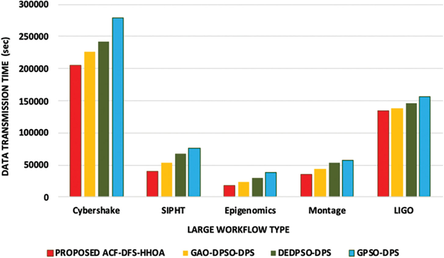
Figure 1: Proposed ACF-DFS-HHOA-Data transmission time with large workflows
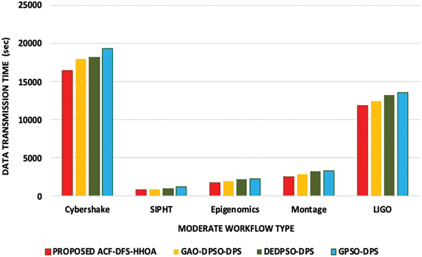
Figure 2: Proposed ACF-DFS-HHOA Data transmission time with moderate workflows
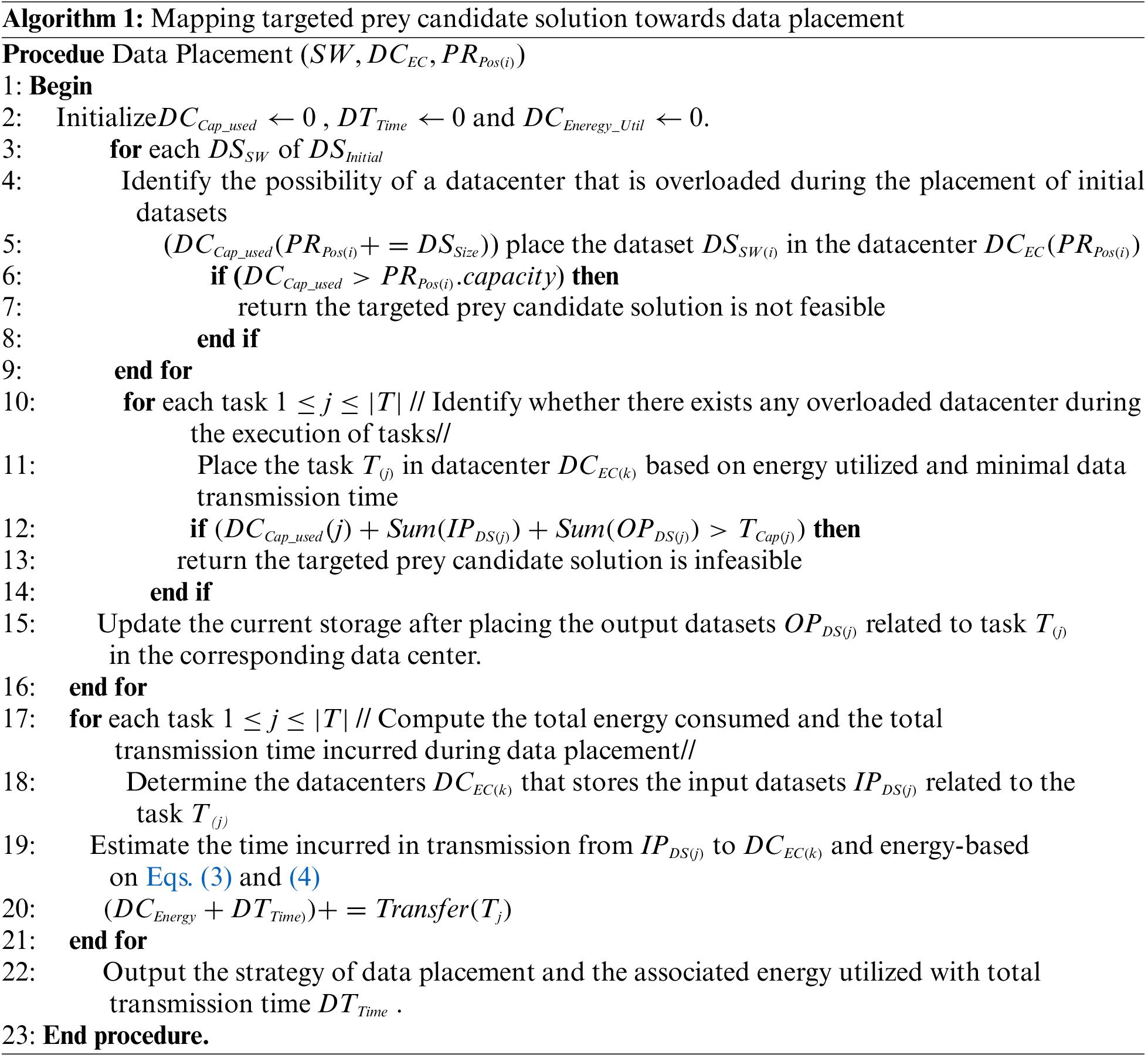
Fig. 1 presents the time incurred in data transmission of the proposed ACF-DFS-HHOA data placement strategy and the benchmarked algorithms. Fig. 2 demonstrates the time incurred in data transmission of the proposed ACF-DFS-HHOA data placement strategy and the benchmarked GAO-DPSO-DPS, DEDPSO-DPS and GPSO-DPS schemes with moderate scientific workflows. Fig. 3 portrays the proposed ACF-DFS-HHOA with small workflows reduced the average data transmission time by 7.21%, 8.59% and 9.38%, superior to the benchmarked GAO-DPSO-DPS, DEDPSO-DPS and GPSO-DPS schemes.
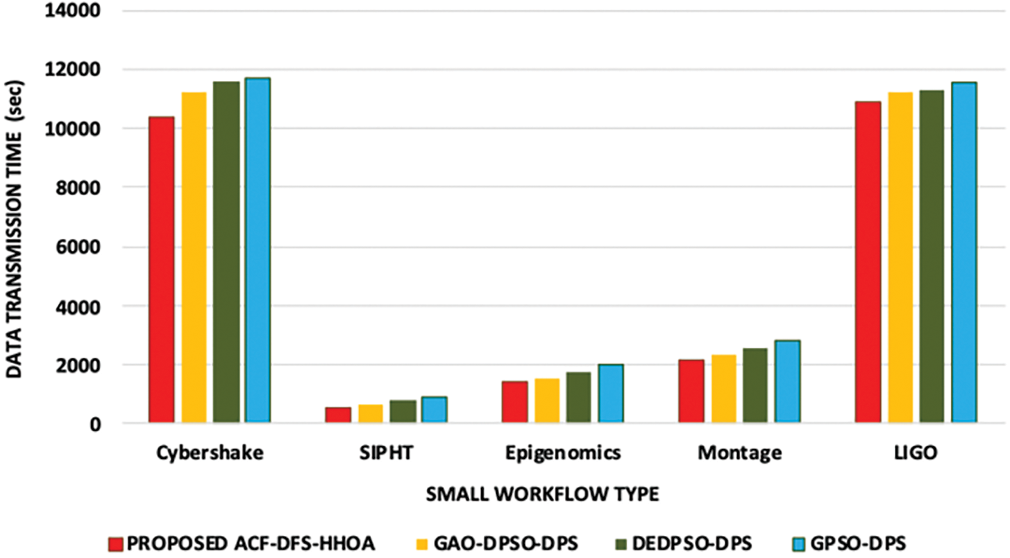
Figure 3: Proposed ACF-DFS-HHOA Data transmission time with small workflows
5.2 Performance Evaluation of Proposed ACF-DFS-HHOA Algorithm Based on Different Edge Datacenters with Moderate Workflows
In this experiment, the proposed ACF-DFS-HHOA data placement strategy and the benchmarked GAO-DPSO-DPS, DEDPSO-DPS and GPSO-DPS schemes are compared based on data transmission time with different edge datacenters and moderate number of scientific workflows. Figs. 4 and 5 present the data transmission time incurred with respect to the scientific workflows of LIGO and Cybershake under a different number of edge data centers. Figs. 6 and 7 presents the data transmission time incurred by the proposed ACF-DFS-HHOA data placement strategy and the benchmarked GAO-DPSO-DPS, DEDPSO-DPS and GPSO-DPS schemes with respect to the scientific workflows of Epigenomics and SIPHT under a different number of edge data centers.
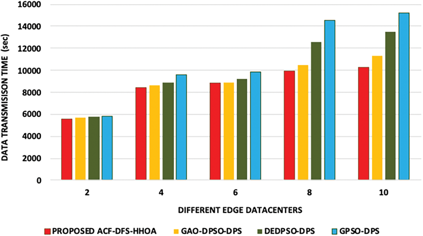
Figure 4: Proposed ACF-DFS-HHOA-Data transmission time with different edge datacentres under moderate workflows (LIGO)
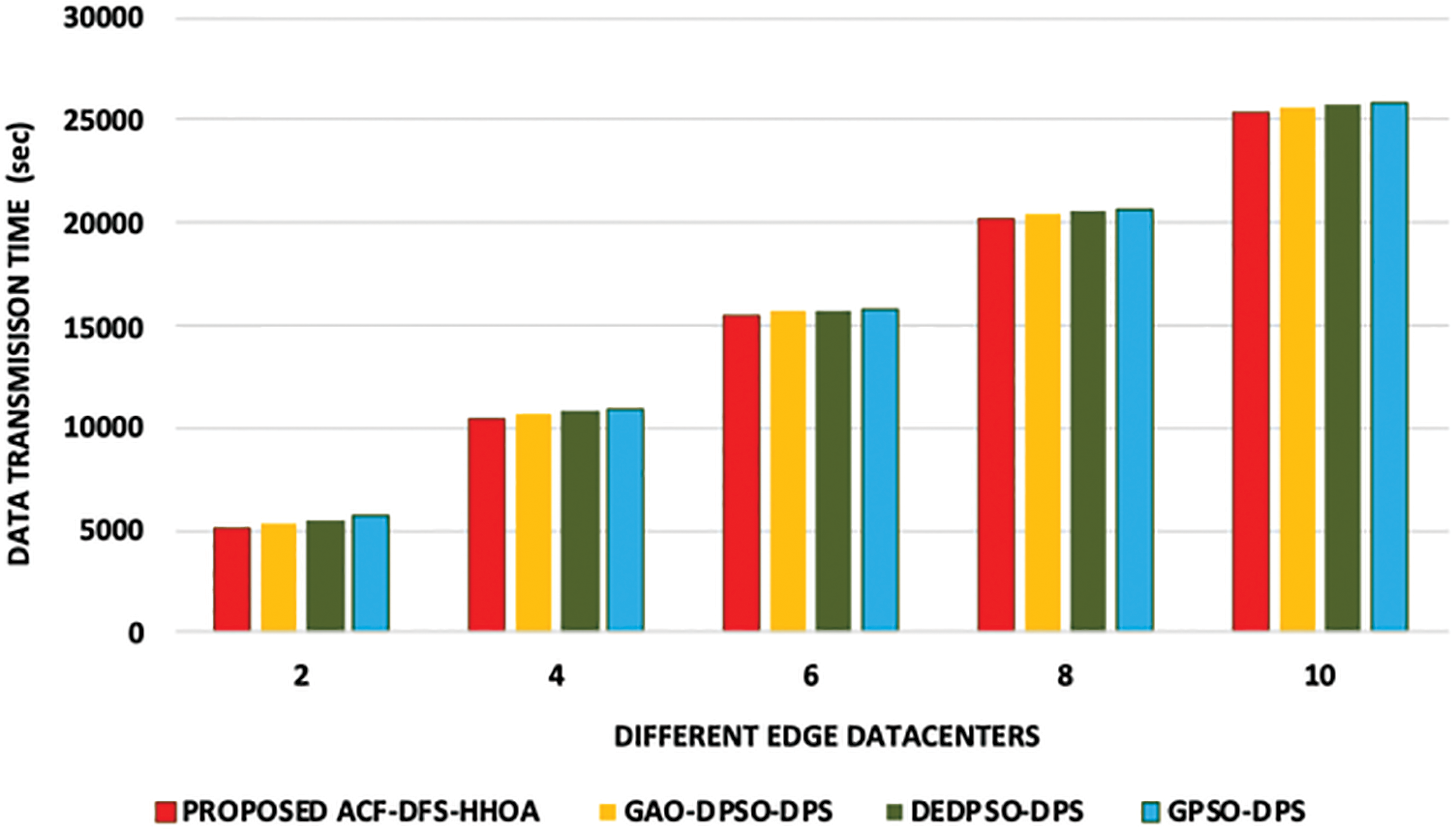
Figure 5: Proposed ACF-DFS-HHOA-Data transmission time with different edge datacentres under moderate workflows (Cybershake)

Figure 6: Proposed ACF-DFS-HHOA-Data transmission time with different edge datacentres under moderate workflows (Epigenomics)
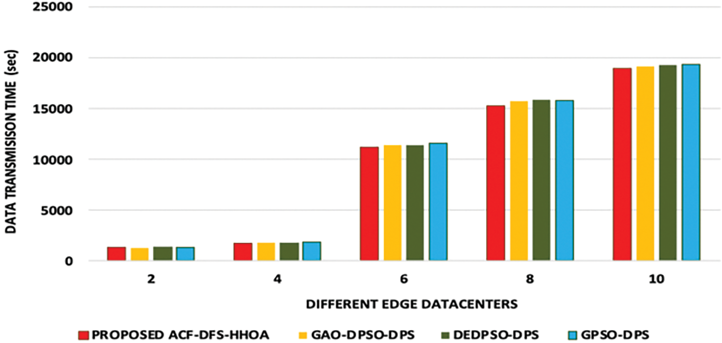
Figure 7: Proposed ACF-DFS-HHOA-Data transmission time with different edge datacentres under moderate workflows (SIPHT)
In addition, Fig. 8 highlights the data transmission time incurred by the proposed ACF-DFS-HHOA data placement strategy and the benchmarked GAO-DPSO-DPS, DEDPSO-DPS and GPSO-DPS schemes with respect to the scientific workflows of Montage under a different number of edge data centers.
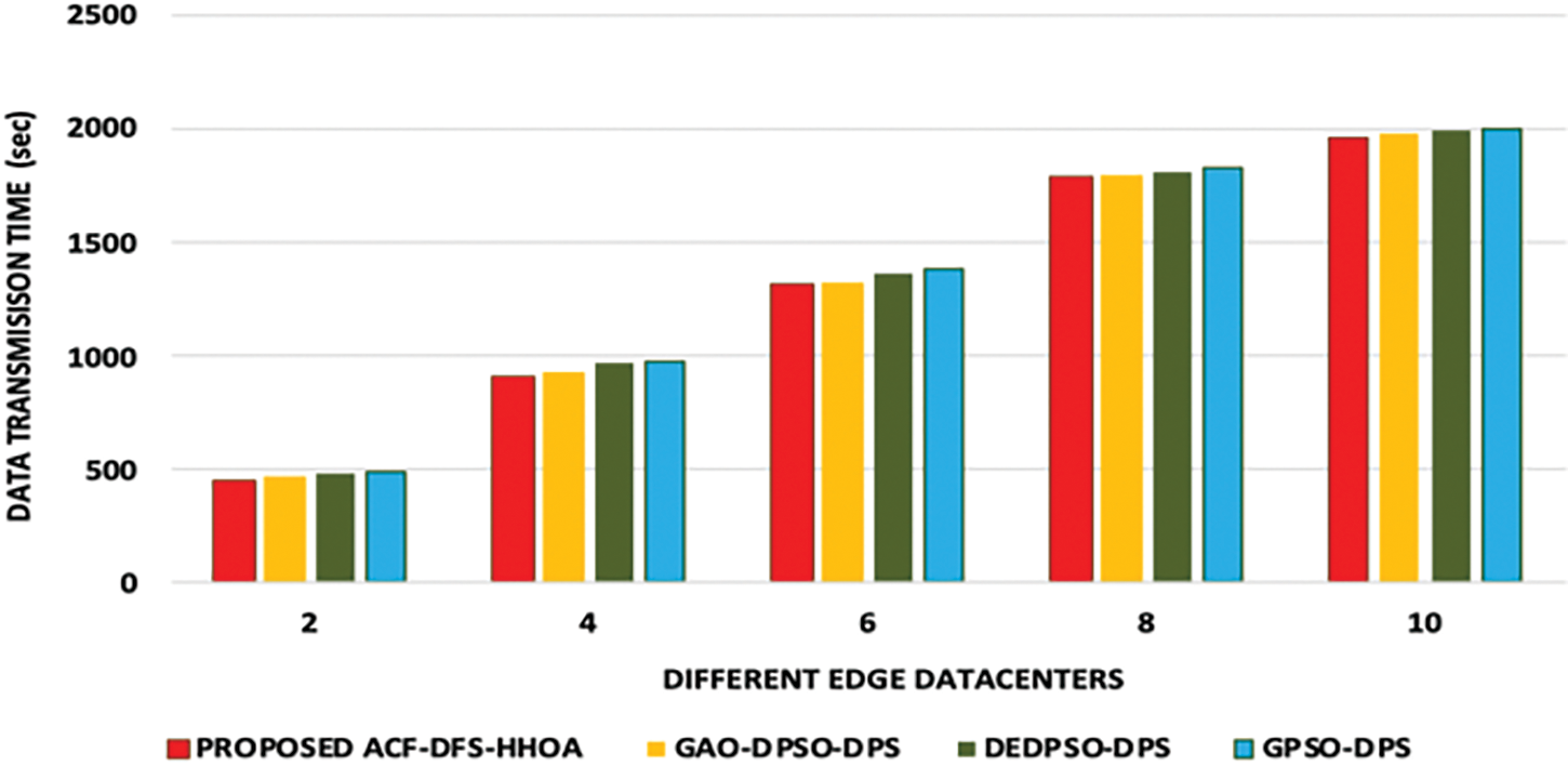
Figure 8: Proposed ACF-DFS-HHOA-Data transmission time with different edge datacentres under moderate workflows (Montage)
5.3 Performance Evaluation of Proposed ACF-DFS-HHOA Algorithm Based on Baseline Storage Capacity Multipliers with SIPHT and Epigenomics Workflows
In this part of the analysis, Figs. 9 and 10 demonstrate the proposed ACF-DFS-HHOA scheme with large workflows minimized the average energy consumption ratio by 5.68%, 6.84% and 10.32%, better than the schemes used for comparison. Moreover, the proposed ACF-DFS-HHOA scheme with moderate workflows is also confirmed to minimize the average energy consumption ratio by 6.74%, 8.68% and 11.92% benchmarked GAO-DPSO-DPS, DEDPSO-DPS and GPSO-DPS schemes.
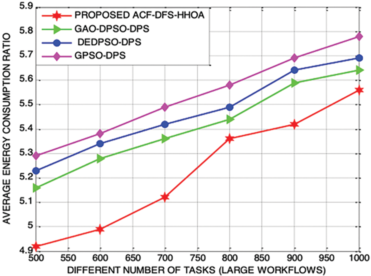
Figure 9: Proposed ACF-DFS-HHOA-Average energy consumption ratio with large workflows
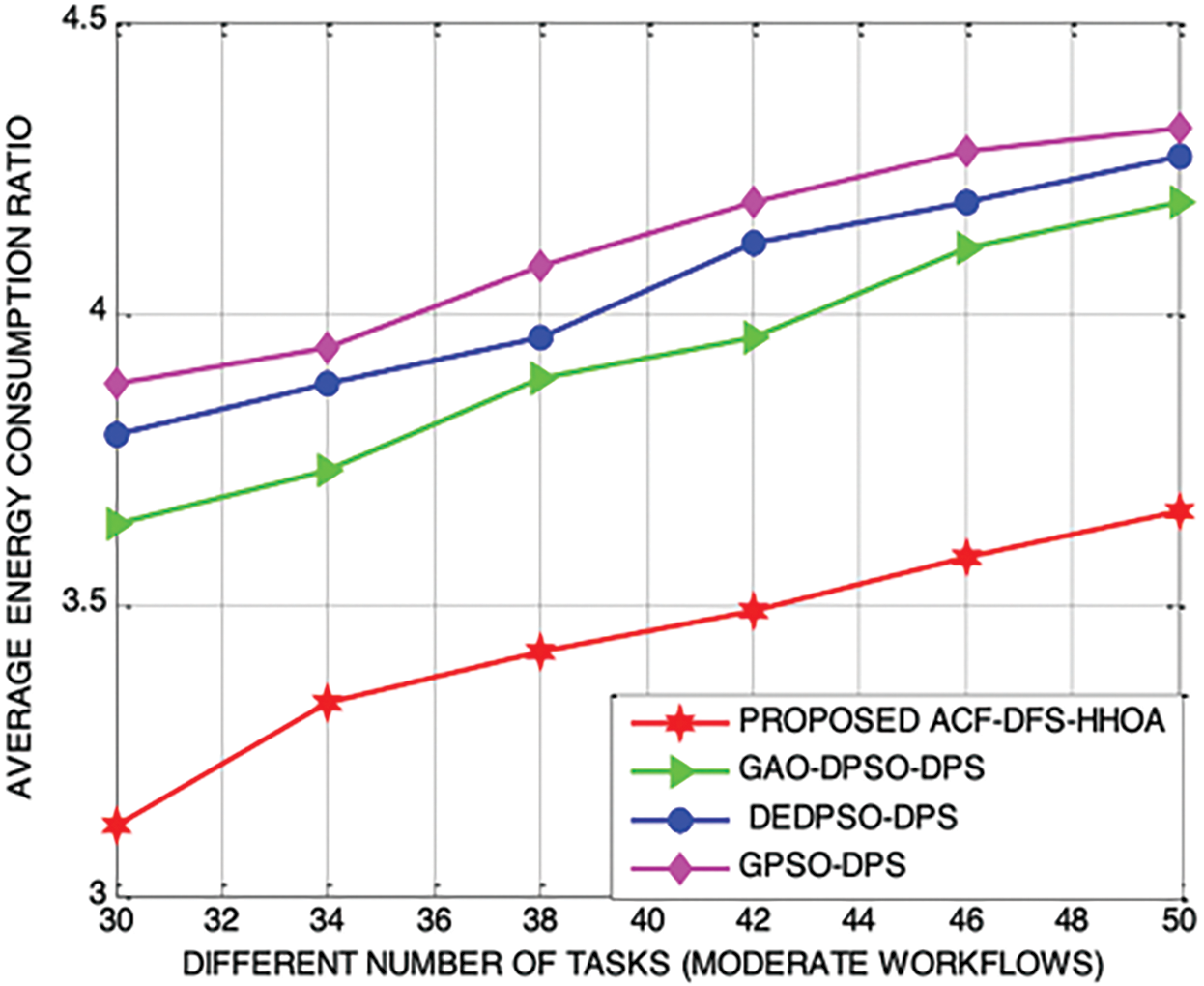
Figure 10: Proposed ACF-DFS-HHOA-Average energy consumption ratio with moderate workflows
In addition, Fig.11 depicts the performance of the proposed ACF-DFS-HHOA and the benchmarked schemes with different number of tasks associated with the small workflows the Average Energy Consumption Ratio by 5.62%, 6.94% and 8.69%.
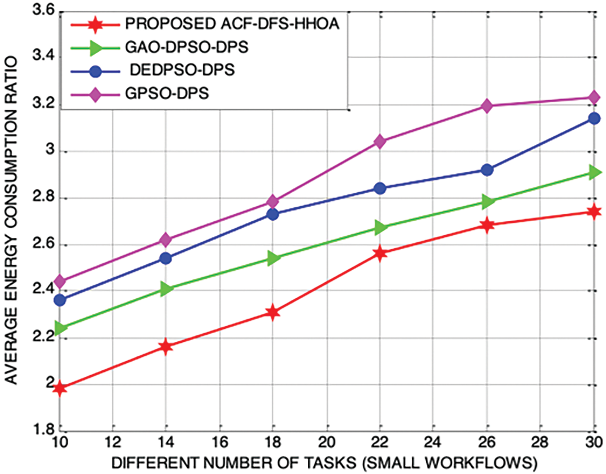
Figure 11: Proposed ACF-DFS-HHOA-Average energy consumption ratio with small workflows
In this paper, ACF-DFS-HHOA was proposed with the core objective of attaining optimal data placement strategy for a specific scientific workflow by reducing data transmission time and the energy utilization aunder the constraints of each datacentre storage capacity and energy threshold of the datacentre. It introduced the strategies of an adaptive cooperative and dispersed foraging into HHOA for superior guidance of the position updates that improve population diversity and effectively prevent the algorithm from being trapped into local optimality point. It also included a randomly shrinking exponential function for establishing a potential tradeoff between exploitation and exploration. As a part of the future plan, it is also planned to formulate a wingsuit optimization algorithm-based data placement strategy and compare it with the proposed ACF-DFS-HHOA to determine the degree of exploitation and exploration attributed by them during the searching process.
Funding Statement: The authors has no specific funding for this study.
Conflicts of Interest: The authors declare that they have no conflicts of interest to report regarding the present study.
References
1. G. Juve, A. Chervenak, E. Deelman, S. Bharathi, G. Mehta et al., “Characterizing and profiling scientific workflows,” Future Generation Computer Systems, vol. 29, no. 3, pp. 682–692, 2013. [Google Scholar]
2. J. Yu, R. Buyya and K. Ramamohanarao, Workflow scheduling algorithms for grid computing. In: Metaheuristics for Scheduling in Distributed Computing Environments. Berlin: Springer, pp. 173–214, 2008. [Google Scholar]
3. J. Shuja, S. A. Madani, K. Bilal, K. Hayat, S. U. Khan et al., “Energy-efficient data centers,” Computing, vol. 94, no. 12, pp. 973–994, 2012. [Google Scholar]
4. S. Didi, K. Bahhous, M. Zerfaoui, Z. Aboulbanine, H. Ouhadda et al., “Experimental validation of a linac head geant4 model under a grid computing environment,” Biomedical Physics & Engineering Express, vol. 8, no. 2, pp. 025007, 2022. [Google Scholar]
5. A. Beloglazov, R. Buyya, Y. C. Lee and A. Zomaya, “A taxonomy and survey of energy-efficient data centers and cloud computing systems,” Advances in Computers, vol. 82, pp. 47–111, 2011. [Google Scholar]
6. R. Kleminski, P. Kazienko and T. Kajdanowicz, “Analysis of direct citation, co-citation and bibliographic coupling in scientific topic identification,” Journal of Information Science, vol. 48, no. 3, pp. 349–373, 2022. [Google Scholar]
7. J. Sun, L. Yin, M. Zou, Y. Zhang, T. Zhang et al., “Makespan-minimization workflow scheduling for complex networks with social groups in edge computing,” Journal of Systems Architecture, vol. 108, pp. 101799, 2020. [Google Scholar]
8. L. Cui, J. Zhang, L. Yue, Y. Shi, H. Li et al., “A genetic algorithm based data replica placement strategy for scientific applications in clouds,” IEEE Transactions on Services Computing, vol. 11, no. 4, pp. 727–739, 2018. [Google Scholar]
9. M. K. Hasan, M. Akhtaruzzaman, S. R. Kabir, T. R. Gadekallu, S. Islam et al., “Evolution of industry and blockchain era: Monitoring price hike and corruption using BIoT for smart government and industry 4.0,” IEEE Transactions on Industrial Informatics, vol. 18, no. 12, pp. 9153–9161, 2022. [Google Scholar]
10. B. Liang, X. Dong, Y. Wang and X. Zhang, “Memory-aware resource management algorithm for low-energy cloud data centers,” Future Generation Computer Systems, vol. 113, pp. 329–342, 2020. [Google Scholar]
11. Z. Chen, J. Hu, G. Min and X. Chen, “Effective data placement for scientific workflows in mobile edge computing using genetic particle swarm optimization,” Concurrency and Computation: Practice and Experience, vol. 33, no. 8, pp. e5413, 2021. [Google Scholar]
12. V. D. Reddy, B. Setz, G. S. V. R. K. Rao, G. R. Gangadharan and M. Aiello, “Metrics for sustainable data centers,” IEEE Transactions on Sustainable Computing, vol. 2, no. 3, pp. 290–303, 2017. [Google Scholar]
13. A. A. Heidari, S. Mirjalili, H. Faris, I. Aljarah, M. Mafarja et al., “Harris hawks optimization: Algorithm and applications,” Future Generation Computer Systems, vol. 97, pp. 849–872, 2019. [Google Scholar]
14. A. S. Menesy, H. M. Sultan, A. Selim, M. G. Ashmawy and S. Kamel, “Developing and applying chaotic harris hawks optimization technique for extracting parameters of several proton exchange membrane fuel cell stacks,” IEEE Access, vol. 8, pp. 1146–1159, 2020. [Google Scholar]
15. X. Zhang, K. Zhao and Y. Niu, “Improved harris hawks optimization based on adaptive cooperative foraging and dispersed foraging strategies,” IEEE Access, vol. 8, pp. 160297–160314, 2020. [Google Scholar]
16. M. Vasudevan, Y. C. Tian, M. Tang and E. Kozan, “Profile-based application assignment for greener and more energy-efficient data centers,” Future Generation Computer Systems, vol. 67, pp. 94–108, 2017. [Google Scholar]
Cite This Article
 Copyright © 2023 The Author(s). Published by Tech Science Press.
This work is licensed under a Creative Commons Attribution 4.0 International License , which permits unrestricted use, distribution, and reproduction in any medium, provided the original work is properly cited.
 Downloads
 Citation Tools