
 Submit a Paper
 Propose a Special lssue
 Open Access
ARTICLE

Experimental Investigation on the Effect of Seal Presence on the Behavior of Double-Deck Floating Roofs in Cylindrical Steel Storage Tanks
Department of Civil Engineering, College of Engineering, Kermanshah Branch, Islamic Azad University, Kermanshah, Iran
* Corresponding Author: Mehrzad Tahamouli Roudsari. Email:
Structural Durability & Health Monitoring 2023, 17(1), 55-70. https://doi.org/10.32604/sdhm.2022.017458
Received 12 May 2021; Accepted 21 July 2021; Issue published 02 March 2023
 View Full Text
 Download PDF
Abstract
Liquid storage, particularly oil and petrochemical products which are considered hazardous liquid, are an important part of the oil industry. Thin-walled vertical cylindrical steel storage tanks are widely used in recent years. Due to high sensitivity of these structures in an earthquake and other external excitations may lead to catastrophic consequences. For instance, huge economic losses, environmental damages, and casualities, many studies have been done about these structures. past studies showed that liquid storage tanks, equipped with a floating roof, are potentially vulnerable while subjected to seismic loads and earthquake has been considered as one of the most destructive natural hazards. The reason is that such tanks are made of two separated parts (shell and roof) which each may have its own responses; sometimes causing resonance phenomenon and so that, roof movements, roof-fluid interaction, roof-shell interaction, and also the way they are attached should still be investigated. Experimental tests of floating roof’s vertical fluctuation was performed in a full-scale reservoir tank and assessing of the results demonstrated that presence of a seal between floating roof and shell plate can significantly increase damping ratio in liquid sloshing and also suppress the roof`s vertical displacements. In other words, seal can control a floating roof and make it stop moving vertically over few cycles.Keywords
In the oil and petrochemical industries around the world, thin-walled tanks are used to store petroleum products, which are mainly made of steel and concrete. Concrete and steel tanks have special use based on their mechanical characteristics, which due to the potentials of steel reservoir tanks, this type of tank are more widely applicable than others. In the oil and gas industry, tanks are often made of steel and are geometrically vertical cylinder. Steel tanks were highly regarded for simpler way for the operation, acceptable resistance to external forces and internal hydro-static forces, as well as the possibility of use in various environmental conditions. In natural disasters such as earthquakes, tsunamies, and floods, various and significant damages are caused to the reservoirs, which mainly lead to severe human and financial losses and costs. The importance of oil reservoirs has led researchers to pay special attention to the study of reservoirs and provide solutions to prevent damage to them. There are different types of steel tanks, each with its own application, steel tanks are classified in terms of the type of bracing system, foundation, roof, and H/R Slimming ratio. The most important factor in distinguishing steel tanks is the type of roof. These tanks are divided into three categories according to the type of roof, tanks with fixed roofs, floating roofs, and double roofs. Tanks with floating roofs have two configuration of single-deck and double-deck roofs.
Tanks with floating roofs are structurally composed into two different parts, the tank wall, and the roof. In case of force applied to this type of tank, the wall and the roof give two different and separate responses to the applied force, which are different from the tanks with an integrated roof in this respect. In tanks with a floating roof, the roof is buoyant on the surface of the fluid and has no connection to the wall. In fact, the only interface between the wall and the roof is the seal (Fig. 1). The seal is a structural element that is installed around the roof to fill the gap between the wall and the roof and prevent the roof from wall from collision. The reason is that the diameter of the roof in tanks with a floating roof is less than the diameter of the tank is operational purposes, the free movement of the roof in the vertical direction, as well as preventing the roof and wall from colliding and the possibility of sparks. The seal also prevents gases and fluid vapors from escaping from the tank. There are various types of seals, each with a different function. A seal can be made of steel, rubber, Styrofoam, or other various materials. Duo to the importance of oil reservoir structures, in order to prevent accidents in these structures, it is necessary to study and research the causes of harmful phenomenons and methods to prevent them.
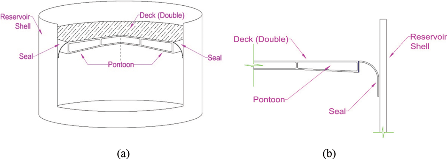
Figure 1: (a) Schematic view of a double deck tank (b) Schematic view of deck, seal and shell detail
Failure in various components of the floating roof causes damage to the roof and eventually the tank (Fig. 2). Seals lose their efficiency over time due to various reasons such as frequent filling and evacuation of the tank, deformation of the wall, and roof impacts to the wall. Seals, as a substantial member of the reservoir, play a very important role in preventing explosions and fire. In case of inefficiency of the seal, by escaping the gases out of the tank and accumulating a significant amount of gas on the roof, combustion conditions and accidents will be easily created (Fig. 2a). Another factor is the malfunction of the roof is damage development in pontoon. Pontoon is another floating roof component that has the task of keeping the roof afloat on the fluid surface. A pontoon is a collection of air-tight boxes that form a ring on the roof, with damage to the pontoon and the penetration of petroleum products into it, the roof becomes heavy and sink (Fig. 2b). Opentop fires and ring fires in general are other types of accidents that may occur due to improper seal operation in oil tanks (Figs. 2c and 2d).
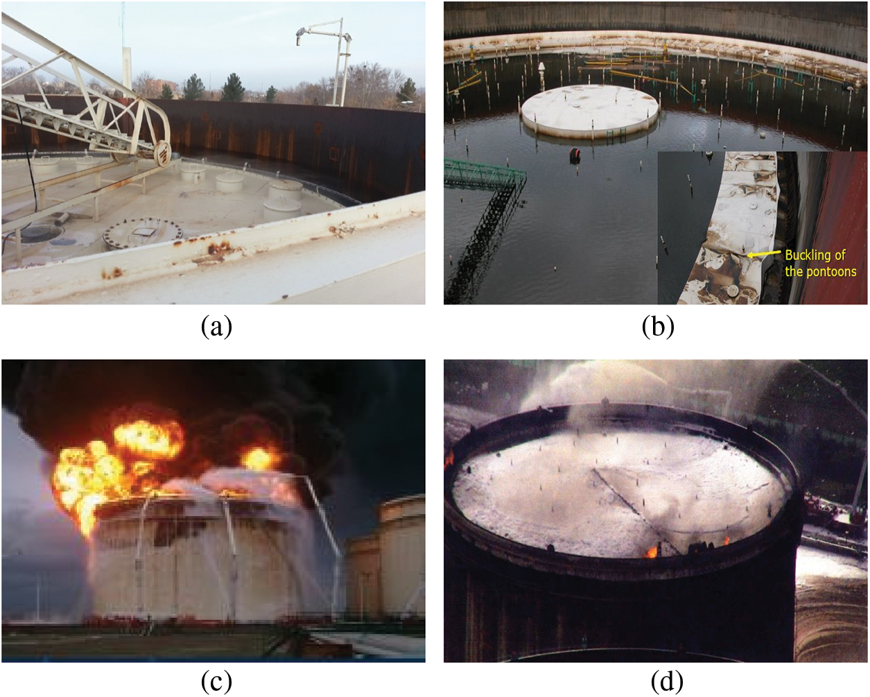
Figure 2: (a) Formation of vapors on the tank due to improper seal operation (b) The roof of the tank sank due to a break in the pontoon (c) Opentop fire in Tokachi-Oki earthquake (d) Ring fire in the tank due to seal failure
As an example for a catastrophic incident due to seal failure, in the summer of 2016, in the Bistoon Petrochemical Complex in Kermanshah, Iran, the storage tank No. 504 of the light end product, which is a light petroleum product with high vapors, exploded. This tank, which was a cylindrical tank with a double-deck roof system, imploded due to the lack of proper seal operation and collected oil vapors into the enclosed space between the two decks and the presence of static electricity as an ignition initiative, which caused the fixed roof to be displaced and thrown to 130 m farther than the tank, while the fluid level inside the tank was only 300 mm. Fortunately, there were no human injuries in this incident, but severe financial damage was inflicted on the complex. The vital role of the seal in the occurrence of this accident is quite obvious. The poor performance of the seal caused petroleum vapors to pass through the seal between the roof and the wall and leaks into between two decks, creating the potential for an explosion. According to officials, the cause of the explosion was electricity (Fig. 3).
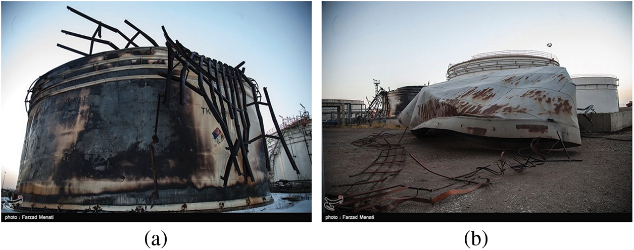
Figure 3: (a) The exploded tank of Bistoon petrochemical complex in 2016 (b) The roof of the tank thrown away after the explosion
Due to the high importance of oil reservoirs, many types of investigations in this field have been done from different perspectives, some of which are mentioned below:
After the 1960 Chile earthquake that severely damaged water reservoirs, considering the movements of the fluid relative to the tank and also the reaction of the reservoir to the movements of the earth, dynamic analyzes were executed by Housner et al. [1]. As a result of which, equations were proposed to determine the relationship between the dynamic characteristics of the reservoir and the free water surface. In this study, a simplified equation was presented to determine the seismic response of elevated water tanks. Nishi et al. [2] examined the proper performance of the floating roof in seismic turbulence in an experimental study. They concluded that the larger the diameter of the tank, the longer the sloshing period, and the higher fluid height will cause a shorter sloshing period. Also, with the occurrence of resonance between fluid and ground displacements, there is a possibility of roof collapse. In this study, they also presented Eqs. (1) and (2) to investigate the sloshing period and wave height based on velocity potential theory, in which D is the reservoir diameter, H is the fluid depth, G is the gravitational acceleration of the earth, and Sv is the velocity response spectrum.
Nishi et al. [3] also examined a full-sized floating roof tank in an experimental study. The aim of this study was to assess the fluid sloshing behavior relations in nonlinear state and to assess the strain developed in the pontoon of the floating roof. Based on the experimental tests, both formulas had accurate answers and the damping coefficient of viscous fluid sloshing in single-deck roofs was derived less than 0.5%. In 2011, Hosseini et al. [4] conducted a numerical study on the behavior of a floating roof tank. By presenting a finite element model and assuming that the sloshing fluid has been suppressed, they investigated the performance of the seal as a radial compressive pre-compressed element in the radial direction of the tank. They concluded that if the maximum distance between the floating roof and the tank wall exceeded the initial length of the compressive pre-compressed spring, the tank is considered damaged. Zama et al. [5] investigated the damage to oil storage tanks during the 2011 Tokyo earthquake. In this study, storage tank damage was classified into three types based on external forces: Tsunami, long-period ground motions, and strong short-period ground motion. In 2017, Hosseini et al. [6] proposed a new method for controlling the seismic movements of a floating roof in floating roof tanks by a suspended ring baffle. SAB (Suspended Annular Baffle) baffles, consists of a ring (with different materials) that is hung on the ceiling by a string. They concluded that the presence of SAB significantly controls the vertical movements of the roof following the sloshing of the fluid and that SAB reduces the maximum height of seismic waves by about 40%.
In studies on petroleum fluid reservoirs in recent years, various researches have been done to evaluate and investigate existing structures failure factors. Various types of damage in petroleum reservoirs, identification of the most common types of failure in reservoirs, the effect of storms on reservoirs and assessing methods using intensifying the dynamic load combination were the items evaluated in the studies. Many reservoir tanks have been tested and studied to conduct experimental assessments on these structures to identify failure modes and seismic responses. The results of these studies showed that flood is the most critical load scenario among dynamic loads for petroleum structures. Evaluation of failure types in petroleum structures indicated that low-amplitude excitation reduces the hydrodynamic response in reservoirs [7–11]. In an experimental study, the “boilover” phenomenon, which is one of the most dangerous types of combustion in oil storage tanks, was investigated. Two tanks with diameters of 2.4 and 4.5 m were evaluated to determine the fire parameters in these structures. Estimation of hot zone growth rate, time required to convert fire to “boilover” phenomenon, and estimation of heat generation amount were investigated [12].
To more accurately evaluate fluid storage tanks, researchers have used different modeling approaches. Important researches include the following: numerical study using finite element model on annular and hydrodynamic stresses and elephant foot buckling, measurement of reservoir settlement with sand foundation, effects of base rotation in high reservoirs, seismic risk against fluid displacement in reservoirs with floating roof, Investigation Seismic behavior of a new finite element model in a storage tank, as well as a multi-level numerical analysis method for coupled systems that can be effectively used to ensure the safety of vertical cylindrical storage tanks for petroleum products. This research showed that it is very difficult to measure the reservoir settlement with a sand foundation during operation. Therefore, numerical analyzes for settlement and vertical displacement appears to be subsidence has a significant effect on the radial deformation of the reservoir wall. It was also found that the percentage reduction in the natural frequency of the impulsive mode remains constant in cases where the conical tank with a slope angle of 30 degrees and 45 degrees, while for tanks with a slope angle of 50 degrees is less. Passive control techniques for seismic protection of chemical plans were investigated in another study which offered applicability of PCT as mitigation strategy [13–17]. In another study, two full-size reservoirs for buckling behavior under general and local differential settlement were investigated using the FEM software model with non-linear geometric algorithm. In these reservoirs, it was proved that local buckling occurs under general differential settlement in the wind girder and continues with a post-buckling behavior [18].
In a study by Spritzer et al. [19] compared the API 650 standard, an American standard for the design of surface tanks, to other well-known design standards, including the Japanese and New Zealand codes. Regulations were examined for several different height ratios for a reservoir matched in terms of geometry and seismic parameters. Hasheminejad et al. [20] investigated the effects of an anti-slosh baffle on the free vibration of a fluid in a relatively filled horizontal cylindrical tank. This study showed that the effects of different baffles on vibration characteristics at various depths are very different from each other. Shabani et al. [21] examined floating roofs under earthquake load using large deflection analysis. They found that the frequency range in which deflection has a suppressing effect is when the earth’s motion is riched in frequency content. Goudarzi et al. [22] investigated hydrodynamic damping in the presence of upper mounted baffle (UMB) in real-size tanks in a numerical research. They checked the accuracy of their analyzed model, investigated the effects of UMB to reduce sloshing waves, and finally proposed a seismic design method for investigating UMB and its effect on suppressing fluid waves.
In recent years, more research has been conducted on the behavior of floating roofs of oil storage tanks. A numerical study was conducted on the effect of oil temperature field in long-term storage in storage tanks with floating roofs. In this study, the effect of floating roof type, insulation layer thickness, and solar radiation was investigated [23]. Also, presenting computational methods for numerical modeling of evaporation of petroleum products and vapor diffusion in an unsteady operating state, investigation of dynamic response of polyuria coated steel tanks under blast loading, assessment of seismic performance of floating roofs without connection in oil storage tanks, and evaluation of fire effect full-scale gasoline tanks with floating roofs have been assessed in more recent research [24–26].
Due to the importance of reservoir structures, so far many studies have been performed on storage tanks with floating roofs, including the study of sloshing behavior, fluid interaction with the structure, fluid interaction with the roof, fluid interaction with the wall, and other researches. In previous studies, seals have been mainly evaluated in terms of exploitation, and the role of the seal as a structural member has not been studied in detail. It seems important to investigate the role of the seal as an interface in the interaction of the roof and the structure. Since the effects of seal on the interaction of the fluid with the roof and wall of the reservoir as well as the overall behavior of the tank under external excitations is an important issue. In this study, experimental studies of seal behavior under external excitements have been investigated. To investigate the effect of seal on the vertical movements of the floating roof, a series of dynamic experiments were performed on a tank with a floating roof with real-sized dimensions. In these studies, by applying excitation to the floating roof and creating free vibration in the roof and fluid, the seal behavior in vertical roof movements was researched, and also the effects of this type of seal were determined in the free vibration graph of the roof. Also in a separate experiment, a sample of seal sheets used in the tested tank was tested under a Quasi-static compressive condition, taking into account the mode of operation in the tank. As a result of these experiments, the amount of damping, due to the presence of the seal in controlling the vibration of the floating roof as well as the nonlinear stiffness of the seal against horizontal shifts of the roof has been obtained. In the following, by providing a definition of the experiments and assessing the results, the effect of the presence of seal on the damping rate and other parameters is investigated.
2 Experimental Program and Setup
An experimental program was prepared in which experiments were executed on a full scale tank at the Kermanshah-Iran oil refinery to investigate the effect of seal on vertical roof vibrations. Also, to investigate the effect of seal on horizontal vibration, a quasi-static experiment was performed on the plate used in the seal in the Structural Research Laboratory of Azad University-Kermanshah Branch. In the reservoir experiments, by fluctuating the floating roof in the vertical direction, free vibration was created in the fluid inside the tank, based on which the vertical displacements of the floating roof as well as the seal demeanor were investigated. In these experiments, by making an initial displacement in the floating roof in the vertical direction and releasing it, the fluid inside the tank starts to vibrate under the force applied by the roof and the roof also vibrates accordingly due to be floating on the fluid. Although the presence of a roof has a significant effect on fluid vibration, in any case, the displacements of the roof are a function of the movements of the fluid. The effect of the seal can be evaluated by evaluating the results of vertical oscillation in the roof. Also, since the seal acts only as a compressive member in the horizontal movements of the roof, the seal subjected to compressive force in a separate quasi-static test in order to obtain a more accurate interpretation of the seal effect in the roof displacements by evaluating the test results and examining the mechanical characteristics.
The tank tested at the Kermanshah Oil Refinery was a Light Straight Run Gasoline (L.S.R.G) with a very light and volatile fluid and high flammability. This tank has a vertical cylindrical geometry with a double-deck type floating roof and a capacity of 450,000 liters with dimensions of 9150 mm in diameter and 7150 mm in height. The roof weight of this tank is about 10 tons and the wall of this tank is made of carbon steel sheets with an average thickness of 4 mm. The seal used in the tank is of seal-master type, which is made of different components with different materials. This type of seal is made of thin steel sheets that fill the space between the roof and the wall in an arc shape, and its arc geometry has a spring-like function. These types of seals have a better efficiency than the other types and in addition to stability in serviceability conditions to prevent the release of gases, they have a good performance against the movements of the roof. Each of the seal components has a specific application that is more related to its serviceability conditions. The secondary seal, which is made of full hard 301-stainless steel with a thickness of 0.7 mm, has a structural function. Fig. 4 shows the tank and its details.
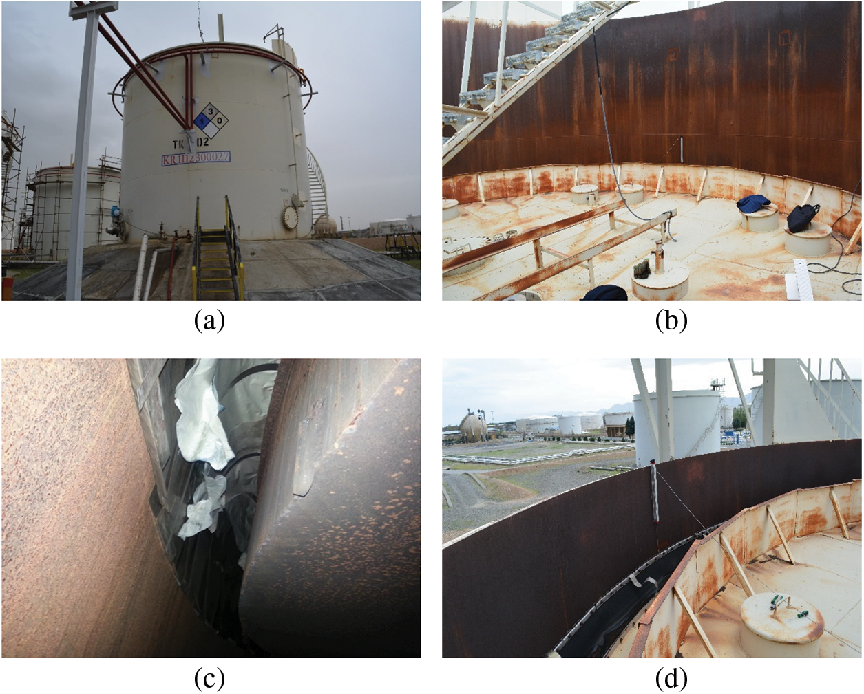
Figure 4: (a) Tested tank in Kermanshah refinery (b) Floating roof of the tank (c) Seal from the inside of the tank (d) Seal from above of the roof
In the tank tests, a crane was used to oscillate the roof, so that a point in the radial perimeter of the roof was connected to the crane hook, and in each test, it was pulled up as much as desired and then released. To investigate the effect of fluid height on the vibration of fluid and the roof as well as seal performance, tests were performed on the tank at three height levels of 3285, 4545 and 5820 mm, which are equivalent to 50%, 67%, and 80% of the tank height, respectively. A crane with a capacity of 392 kN and the possibility of free fall was used to create the excitation. Two LPTs (Linear Potentiometer Transducer) with a range of 450 mm and a measurement accuracy of 0.05 mm were used to calculate the displacement values of the roof rise and its vibration. One of the LPTs was mounted to the tank wall at the point where the roof was raised by a crane and the other was installed on the inverse side of the roof in a radial direction to ensure the accuracy of data collection. A 28-channel Data Logger was used to record the test data, which was used to obtain a roof vibration diagram with appropriate accuracy. Fig. 5 shows the instruments used for this test. Prior to the test, in order to ensure the safety of the work, the gasoline contained in the tank was completely drained and the tank was wiped by High-Pressure Steam for 72 h. The steam out operation was also performed to remove vapors from the upper valve of the tank. To fill the tank, water was used as a fluid in the tank to execute the test, which was due to the specificity of water characteristics and safety considerations.
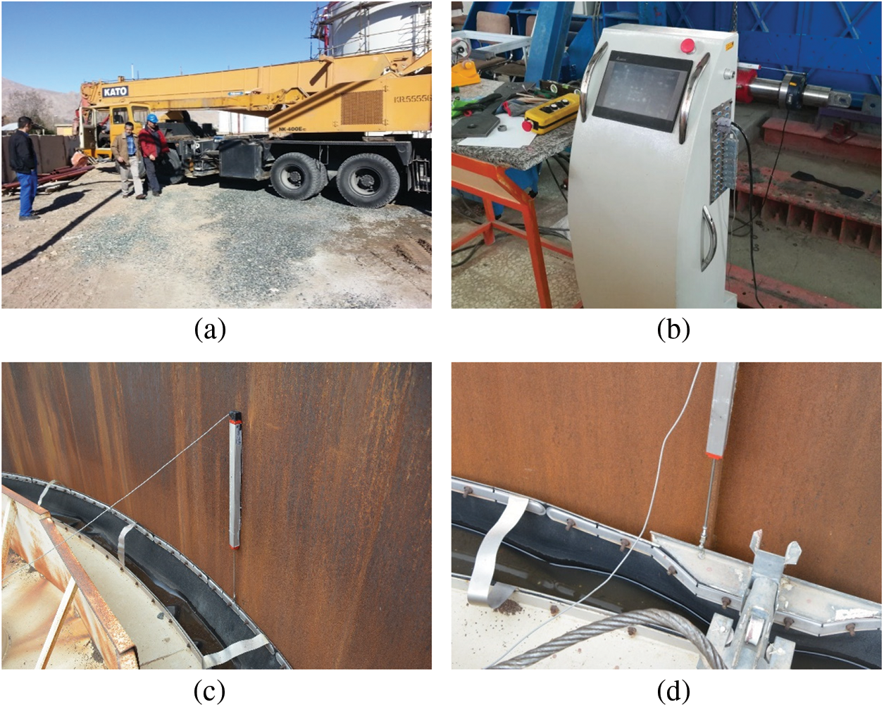
Figure 5: (a) The crane (b) Data logger (c) LPT (d) LPT installation close-up image
To evaluate the seal behavior in horizontal displacements of the roof, a piece of seal plate was tested quasi-statically in the structural laboratory of Kermanshah Azad University. In this experiment, the specimen was made of Stainless Steel-full Hard 301, which is exactly the material of the seal master used in the vertical vibration test. This element with a thickness of 0.7 mm was installed in the form of an arch quite similar to the installation conditions in the tank (Fig. 6). As mentioned, the seal only had a compressive reaction, and for this reason, the experimental test on the seal sheet was executed monotonically. A hydraulic actuator with a capacity of 1500 kN and a course of 600 mm was used for loading in this test. An LPT with a course size of 450 mm and a measurement accuracy of ±0.05 mm was used to measure displacement in the test. 28-channel Data Logger was used to record the amount of force and displacement. The details of the tests and how the fluid and the roof fluctuate, as well as the quasi-static test of the seal in the laboratory are presented below.
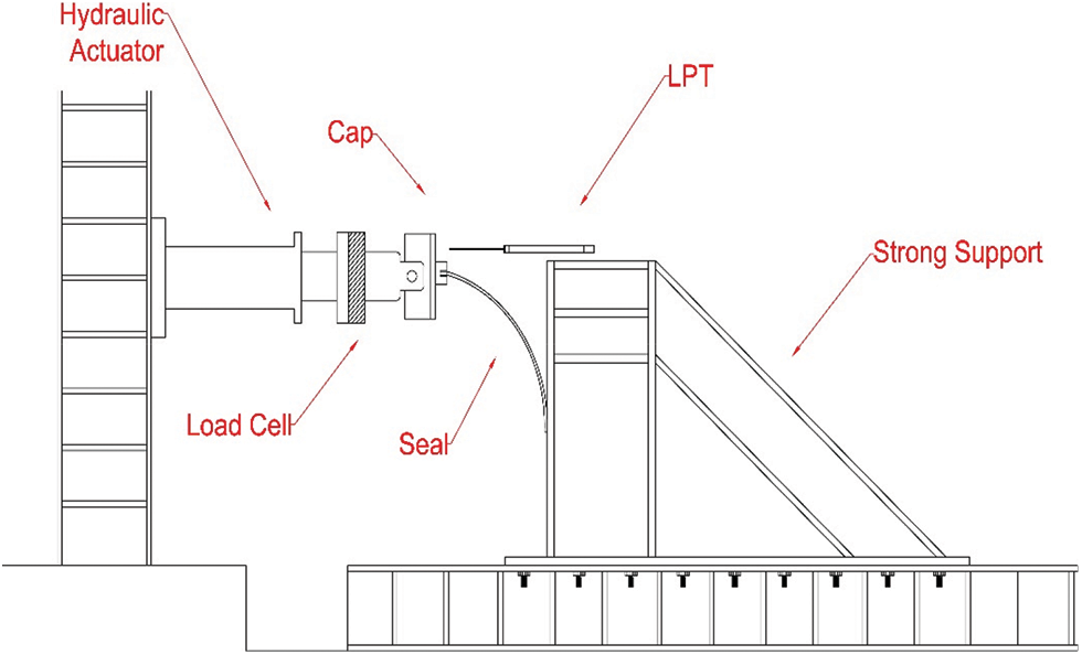
Figure 6: Schematic representation of the quasi-static seal test setup in the laboratory
3.1 Tank Roof Vertical Vibration Tests
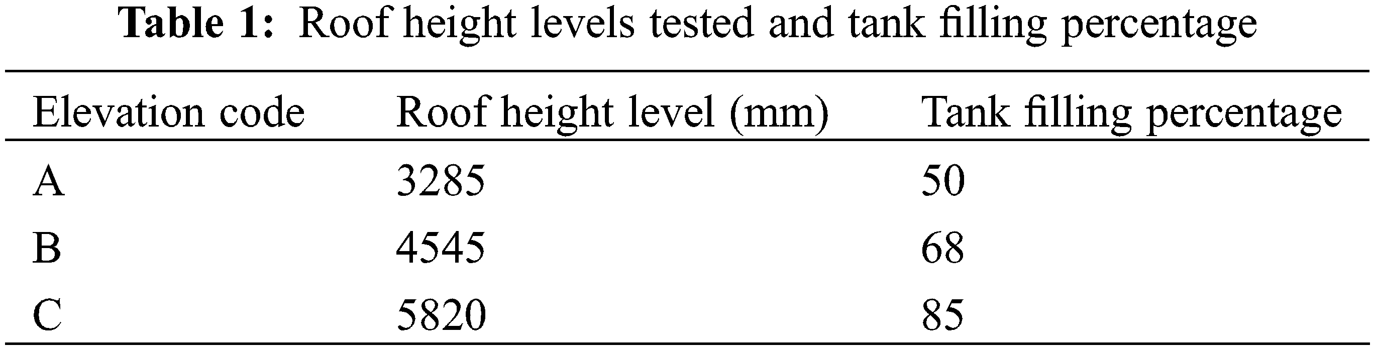
To investigate the effect of seal on the vertical movement of the tank roof, experiments were executed on a tank with real dimensions. Due to the relation between sloshing period and fluid depth (Eq. (1)), experiments were performed at three different height levels on the reservoir to consider the effect of fluid depth in this study. To this aim, in height codes 3285 mm, equivalent to 50% of the total height of the tank, depth 4545 mm, equivalent to 67% of the total height of the tank and 5820 mm, equivalent to 85% of the total height of the tank, the test was performed (Table 1). As previously stated, the LPTs were installed on opposite sides of the roof perimeter and completely attached to the tank wall and were motionless due to the stillness of the tank wall during the test. In these tests, a crane with the possibility of free fall was used to lift and release the floating roof so that the conditions of roof drop and fluctuation in the fluid are close to the real vibration conditions. Also, the tests were repeated twice in each of the altitude codes in order to ensure the accuracy of the test by comparing the vibrating response of the roof. The following are the tests report and their output.
To perform the first level A test, the tank roof was connected to the crane hook at the location where the LPT was installed. After attaching the crane, it raised the roof by 127 mm in the vertical direction, which was read by the data logger from both installed LPTs. It should be noted that the values of up-lifting the roof in the tests were selected based on avoiding plastic deformation in the roof so as not to damage the use of the tank roof. After ensuring the stability of the fluid inside the tank and the roof, the crane executed a free-fall operation and released roof caused fluctuation in the fluid and the roof. This fluctuation ceased moving somewhat after two complete cycles of vibration. In the second test, which was performed in level A, the roof was raised 112 mm and then released. The reason for the difference in the amount of roof lifts in tests of one level is that the amplitude of the free vibration displacements has no significant effect on the sloshing period. In the second test, the fluctuations of the roof were almost similar to the vibrations of the first test at the same level, and after about 8 seconds, the oscillations in the roof and fluid stopped. Time-displacement diagrams for level A tests is shown in Fig. 7.
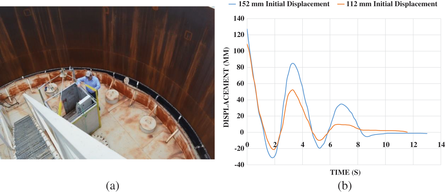
Figure 7: (a) Tank roof at height level A (b) Vertical roof vibration diagram in tests performed in level A
After executing the first stage tests at level A, water was re-injected into the tank until the fluid level reached level B, equivalent to a height of 4545 mm. At this stage, by re-installing the measuring equipments similar to the previous stage, two tests were performed. For the first time, the roof was lifted 154 mm using of the crane and then released. The roof vibration graph shows that at this level it is damped after one cycle and the system stops fluctuating. In the second test at the same level, the roof was pulled up again until 148 mm and then released. Evaluation of the B-level test diagram shows the similarity of the roof vibration in the tests of this level (Fig. 8). The vibration stops after about 6 s.
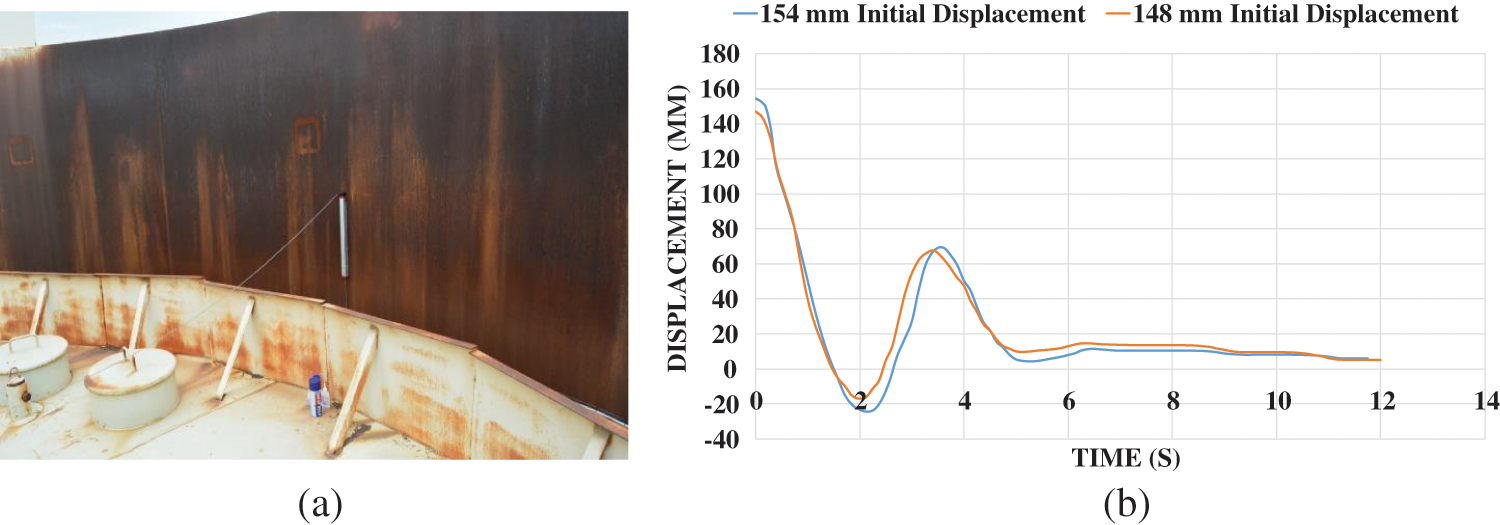
Figure 8: (a) Tank roof at elevation B (b) Time–displacement diagram for level B tests
In the last stage of the vertical vibration tests of the tank roof, to reach the elevation code C, by injecting water into the tank, the fluid height reached to 5820 mm. Level C vertical tests were executed twice as in the previous levels. By installing measuring instrument at this level, in the first stage, the roof was lifted up until 148 mm and released and its vibration with time was recorded. In the second case, the roof began to fluctuate with a change of 135 mm at the initial moment and its release, which according to the test time-displacement of this height level (Fig. 9a) can be said to be acceptable compliance in the experiments. This alignment can be seen and the roof stopped to flactuate in both tests after about 8 s.
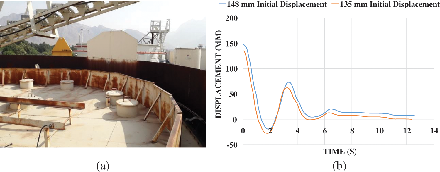
Figure 9: (a) Tank roof in elevation code C (b) Time–displacement diagrams of tests performed at elevation level C
3.2 Experimental Test of Mechanical Properties of Seal
The mechanical behavior of the seal in lateral displacement of the roof was evaluated by a monotonic quasi-static test. The seal used in the tank in which the vertical vibration tests were taken was made of stainless steel 301-full hard sheet with a thickness of 0.7 mm. Seals are made of 700 mm × 300 mm sheets that are fixed to the roof by bolts and on the other side, are in contact with the tank wall, but move freely up and down. To simulate this element behavior in the laboratory, a part of the seal used in the tested tank was evaluated. The quasi-static test setup was designed so that the test element would be loaded precisely like the geometric position of the seal in the tank (Fig. 6). As mentioned, the seal has a completely compressive role due to its geometry around the roof of the tank and also due to the materials used in it and does not act as a tensional component. Therefore, the seal element was subjected to monotonic compressive loading. The test was performed quasi-statically to avoid the dynamic effects of loading on the test diagram. In this experiment, it was assumed that the roof was attached to the tank wall on one side and moved to the opposite side of the tank wall. Due to the fact that the distance between the roof and the wall in the tank tested in the refinery was 200 mm in all directions, the seal was tested in a 400 mm opening. Due to the stated hypotheses, the seal sheet test was performed in the laboratory, the different steps of which are shown in Fig. 10.
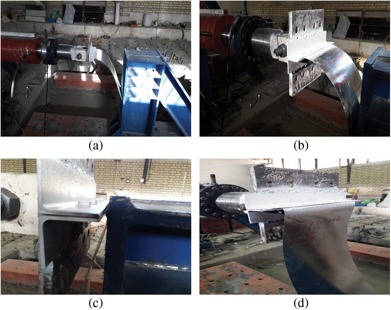
Figure 10: (a) Seal test general setup (b) Seal to hydraulic jack connection using a cap (c) The moment the seal hits the wall and the test is completed (d) Plastic deformation of the seal sheet after the test
The process of testing and loading steps was monitored and performed by the data logger and loading steps were performed based on the displacements stated by the LPT. At the beginning of the test, due to the geometric shape of the seal and the elastic-springy nature of its material, up to 360 mm displacement, almost no resistance was monitored from the sample and the loading practically changed the geometric shape of seal. This change in geometric shape continued until a displacement of 360 mm and then led to growth in force in the sample by applying more displacement by the actuator. From about 360 mm displacement, the value of force increased and as shown in the force-displacement diagram of the sample (Fig. 11), by entering the sample into the plastic phase and creating stable deformations in it, the force required to apply the displacement increased drastically. It withstood a force equivalent to 9.08 kN at a displacement of 400 mm. Based on the use of the seal in the tank and the expectation from the seal in the horizontal movement of the roof, the plastic deformation in the seal can be contemplated the failure point of this element.
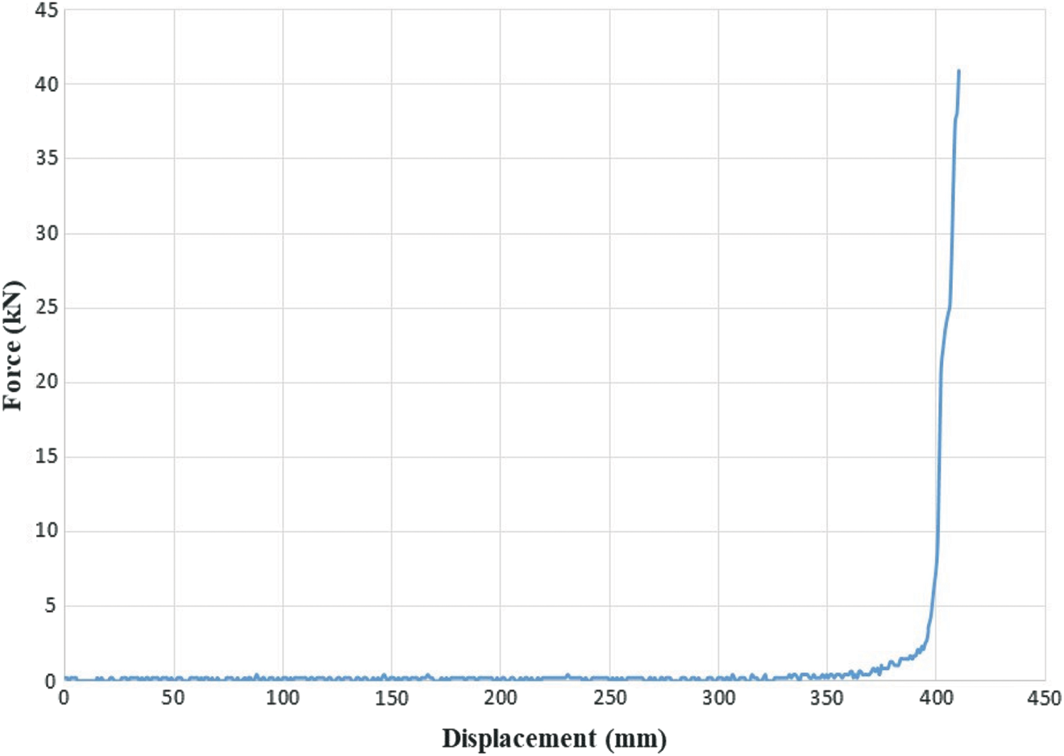
Figure 11: Force–Displacement diagram of the seal sheet experimental test
According to the experiments executed to investigate the vertical vibration of the tank roof, it is possible to obtain a more accurate evaluation of the test results by calculating parameters such as the first period of sloshing and also the damping rate of sloshing in the tank. To this goal, the values of the first sloshing period were calculated for each elevation of the vertical vibration test on the reservoir tank. Also, the values of this parameter were calculated based on Eq. (1) for the corresponding height of each test in order to make a better comparison between the experimental results and Eq. (1) output. In Table 2, the values of the first sloshing period are given based on experimental and numerical results. It can be concluded, the values of the first sloshing period at different elevations of the fluid surface have slight differences, which can be justified given that the amount of the sloshing period is related to the fluid depth.
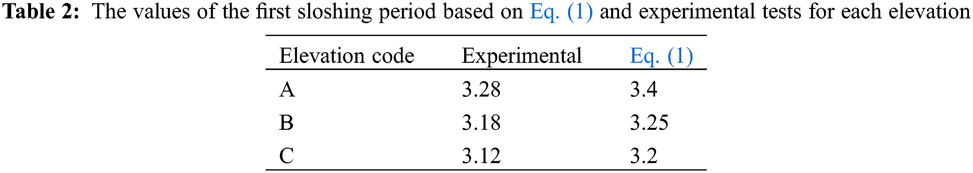
As shown in Table 2, the experimental values of the first sloshing period and the values calculated based on Eq. (1) are different from each other, which according to former researches [6], this disagreement is due to the roof in the tank and its presence effect on the value of the period. Experimental values are obtained from the graphs derived from the test.
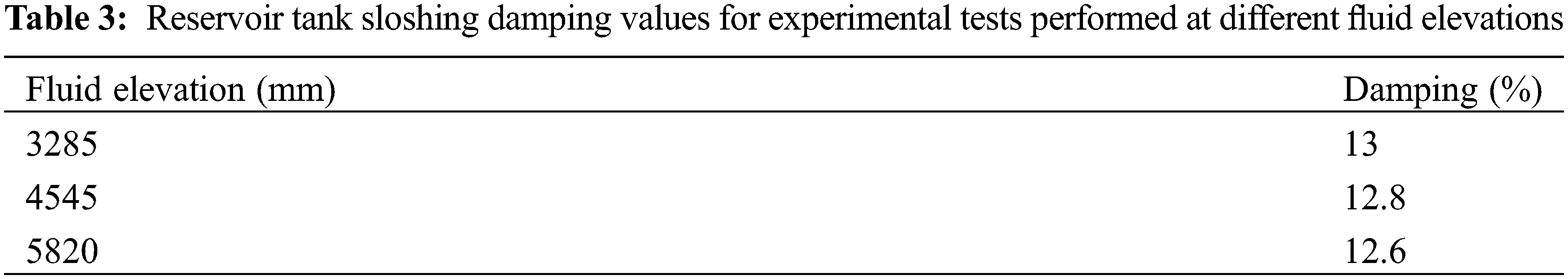
The sloshing damping factor in the reservoir is one of the important factors on which many studies have been done and is one of the sensitive parameters in the design and analysis of reservoirs. In previous studies [2], the sloshing damping on the floating roof without the presence of the seal is about 0.5%. Comparing the results of the present study with the previous studies results can express the effect of the presence of seal more accurately. According to the diagrams obtained from experimental tests, it can be seen that the roof vibration dampens rapidly and the roof vibrates with one to two cycles. Sloshing damping calculations were performed based on the damping relationship (Eq. (3)), where Ui and Ui + 1 are the displacement of a point at moment i and moment i + 1 in two consecutive fluctuation cycles, respectively. Sloshing damping calculations in the reservoir are performed on the assumption that the structural system is a single degree of freedom.
As a result of the damping calculations given in Table 3, it is inferred that although in previous studies [2], it was stated that the sloshing damping in a tank with a floating roof without the seal is about 0.5%, in experiments executed with The presence of seal in the roof, damping is estimated about 12% to 14%. This comparison shows that the presence of a seal can cause much higher damping in the tank structural system with a floating roof.
In the experimental test of lateral displacements of the roof according to the output diagram of the seal test, the maximum force that the seal has endured is equal to 9.08 kN, which was equivalent to 400 mm in displacement. The stiffness of the steel sheet is calculated from Eq. (4) where in this equation F is force, K is hardness and U is displacement.
The maximum stiffness value Kmax is calculated based on the value of the displacement in which the specimen has withstood the maximum force. In the quasi-static test of the seal sheet, this displacement point was equal to 400 mm, according to which the maximum stiffness value is equal to 22.07 kN/m. Considering the 300 mm width of the sheet used in the quasi-static monotonic test of the seal sheet and the stiffness calculations of the sheet, it can be said that the presence of the seal in the floating roof system can be modeled with springs with compressive stiffness of 75.6 kN/m in each meter of the floating roof perimeter. Fig. 12 shows this type of proposed model in which the springs will be activated only under compressive forces.
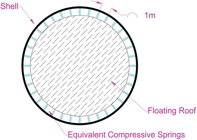
Figure 12: Schematic view of the tank roof and equivalent springs system
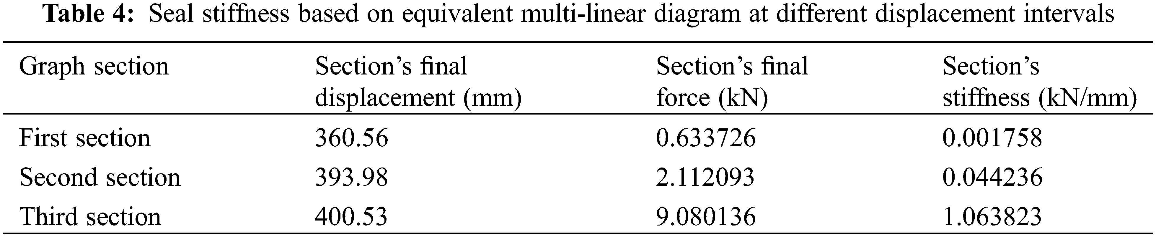
According to the experimental test result of the seal sheet, it is possible to determine a multi-linear equivalent diagram based on the force-displacement diagram of this test in which the stiffness in the sheet is classified into different intervals. Fig. 13 and Table 4 shows the multi-linear equivalent graph and the stiffness values in each of these intervals. Based on the results, the seal stiffness in the range of 0 mm to about 360 mm is so small that it can be ignored, while the maximum value of stiffness in displacement is between 394 to 400 mm, based on which, this interval can be considered as the seal hardening stage vs. external excitements.
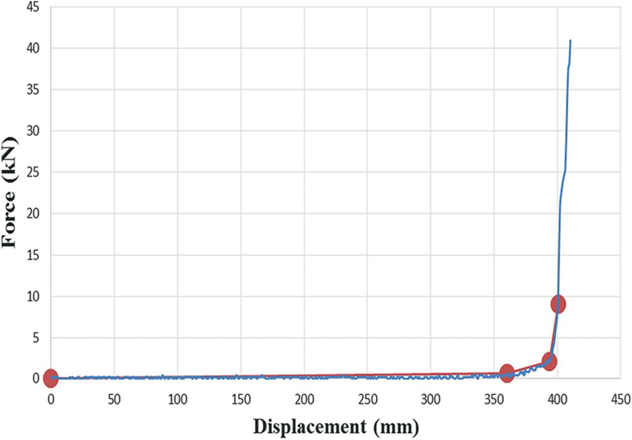
Figure 13: Multi-linear graph for seal sheet experimental results
There are different methods for numerical modeling of seal performance. based on the finite element method, it is possible to assume the rigidity of the roof and wall by using S4R element and also by using adaptive meshing systems for modeling the fluid containing the tank, roof and fluid movements and interaction. To model the stiffness of the seal and their resistance to external loads, the seals are modeled as purely compressive springs with a certain stiffness obtained from the seal performance test. This can determine the value of seal’s compressive strength in various earthquakes and other loads.
The dynamic behavior of steel storage tanks with floating roofs under seismic loads have always been studied regarding their high importance and based on past accidents that happened to this type of storage tanks due to natural disasters particularly earthquakes. In this study, experimental tests were performed to investigate the effects of Seal-master on the vertical free-vibration of the floating roof of a full-size tank. Also, in a quasi-static test, the horizontal displacement of the roof and seal performance were examined and the mechanical properties of the seal were evaluated.
Seal-master seismic performance was evaluated in both vertical and horizontal directions. The presence of the seal-master has a very significant effect on suppressing the fluctuations and horizontal impact movements caused by interactions between the tank’s roof and shell. By comparing the results of this study with previous studies, it is obvious that the seal-master systems have a significant effect on suppressing the fluctuations and impact displacements of the floating roof to shell plate. In this study, it was observed that seal-master severely damps the vibration of the roof and the roof stops moving during two complete vibrational cycles. In the case of lateral displacements and roof’s impact on the wall, the seal-master reacts like a system of compressive springs with a certain stiffness, located all around the roof in a radial direction that Resists the relocation of the roof. An important point is that assumed springs should be considered as only compression element. Thus, the tensional performance of seal-master should not be taken into account. Regarding tank’s cylindrical geometry in every applied acceleration direction, seal-master can resist and for every two opposite points in the radial direction there is at least one that is standing against lateral forces at any moment.
In vertical free fluctuation tests, the friction of the seal with the wall caused the roof to completely damp and stops to flactuate after one or two cycles of vibration. This mode of operation can be considered a useful feature in controlling floating roof displacements and subsequently suppressing the motions of impounded liquid, which may reduce the damage risk for the roof and tank. The first period of sloshing was calculated as a determining parameter in the vibration displacements of the roof for the experiments performed, which was in a good agreement with the previous studies that calculated this factor (Eq. (1)). In the vertical vibration test, it was shown that unlike the low damping of a floating roof system without seal, floating roof tanks with the seal-master system have far higher damping ratio up to 14% (approximately 30 times higher) which can be the most important factor of superiority in using seal-master in tanks with a floating roof.
The quasi-static test of the horizontal displacement of the roof in the laboratory showed the spring-like behavior of the seal in lateral movements of the roof could resist roofs hitting motions in radial directions. In this test, it was showed that the seal as a compressive spring maintains the distance between the floating roof and the tank shell, which stiffness coefficient increases while the roof’s approaching the wall. At the moment that the seal changes shape and does not return to its previous geometry seal-master is considered to be vulnerable.
Funding Statement: The authors received no specific funding for this study.
Conflicts of Interest: The authors declare that they have no conflicts of interest to report regarding the present study.
References
1. Housner, G. W. (1963). The dynamic behavior of water tanks. Bulletin of the Seismological Society of America, 53(2), 381–387. https://doi.org/10.1785/BSSA0530020381 [Google Scholar] [CrossRef]
2. Nishi, H., Yamada, M., Zama, S., Hatayama, K., Sekine, K. (2008). Experimental study on the sloshing behavior of the floating roof using a real tank. Journal of High Pressure Institute of Japan, 46(1), 4–17. [Google Scholar]
3. Nishi, H., Yamada, M., Zama, S. (2008). Experimental study of floating roof integrity for seismic sloshing under long-period strong ground motion. Proceedings of the 2nd International Symposium for “Integrated Predictive Simulation System for Earthquake and Tsunami Disaster,” pp. 97–102. Tokyo, Japan. [Google Scholar]
4. Hosseini, M., Soroor, A., Sardar, A., Jafarieh, F. (2011). A simplified method for seismic analysis of tanks with floating roof by using finite element method: Case study of Kharg (Southern Iran) Island tanks. Procedia Engineering, 14, 2884–2890. https://doi.org/10.1016/j.proeng.2011.07.363 [Google Scholar] [CrossRef]
5. Zama, S., Nishi, H., Hatayama, K., Yamada, M., Yoshihara, H. et al. (2012). On damage of oil storage tanks due to the 2011 off the Pacific Coast of Tohoku Earthquake (Mw9.0). Proceedings of the 15th World Conference on Earthquake Engineering (WCEE), pp. 1–10. Japan. [Google Scholar]
6. Hosseini, M., Goudarzi, M. A., Soroor, A. (2017). Reduction of seismic sloshing in floating roof liquid storage tanks by using a suspended annular baffle (SAB). Journal of Fluids and Structures, 71, 40–55. https://doi.org/10.1016/j.jfluidstructs.2017.02.008 [Google Scholar] [CrossRef]
7. Zdravkov, L., Pantusheva, M. (2019). Typical damage in steel storage tanks in operation. Procedia Structural Integrity, 22, 291–298. https://doi.org/10.1016/j.prostr.2020.01.037 [Google Scholar] [CrossRef]
8. Qin, R., Zhu, J., Khakzad, N. (2020). Multi-hazard failure assessment of atmospheric storage tanks during hurricanes. Journal of Loss Prevention in the Process Industries, 68, 104325. https://doi.org/10.1016/j.jlp.2020.104325 [Google Scholar] [CrossRef]
9. Hatayama, K., Nishi, H., Hayashi, M., Tokutake, K. (2020). Damage to oil tanks caused by severe strong ground motion due to the 2018 Hokkaido, Japan Iburi-Tobu Earthquake (Mw6.6). Pressure Vessels and Piping Conference, vol. 83891, V009T09A012. American Society of Mechanical Engineers. [Google Scholar]
10. Kirtas, E., Rovithis, E., Makra, K. (2020). On the modal response of an instrumented steel water-storage tank including soil-structure interaction. Soil Dynamics and Earthquake Engineering, 135, 106198. https://doi.org/10.1016/j.soildyn.2020.106198 [Google Scholar] [CrossRef]
11. Zhang, C., Wan, L., Magee, A. R., Han, M., Jin, J. et al. (2019). Experimental and numerical study on the hydrodynamic loads on a single floating hydrocarbon storage tank and its dynamic responses. Ocean Engineering, 183, 437–452. https://doi.org/10.1016/j.oceaneng.2019.05.012 [Google Scholar] [CrossRef]
12. Berahman, F., Behnamfar, F. (2009). Probabilistic seismic demand model and fragility estimates for critical failure modes of un-anchored steel storage tanks in petroleum complexes. Probabilistic Engineering Mechanics, 24(4), 527–536. https://doi.org/10.1016/j.probengmech.2009.03.005 [Google Scholar] [CrossRef]
13. Spritzer, J. M., Guzey, S. (2017). Nonlinear numerical evaluation of large open-top aboveground steel welded liquid storage tanks excited by seismic loads. Thin-Walled Structures, 119, 662–676. https://doi.org/10.1016/j.tws.2017.07.017 [Google Scholar] [CrossRef]
14. Minagawa, K., Paolacci, F. (2020). Passive control techniques for seismic protection of chemical plants. Pressure Vessels and Piping Conference, vol. 83891, V009T09A007. American Society of Mechanical Engineers. [Google Scholar]
15. Musa, A., Damatty, A. (2018). Effect of vessel base rotation on the seismic behaviour of conical shaped steel liquid storage tanks. Engineering Structures, 166, 454–471. https://doi.org/10.1016/j.engstruct.2018.03.075 [Google Scholar] [CrossRef]
16. Stefano, C., Paolacci, F., Dolšek, M. (2020). Seismic risk assessment of liquid overtopping in a steel storage tank equipped with a single deck floating roof. Journal of Loss Prevention in the Process Industries, 67, 104269. https://doi.org/10.1016/j.jlp.2020.104269 [Google Scholar] [CrossRef]
17. Belostotsky, A., Pavel, M., Akimov, A., Irina, N. (2016). Multilevel methodology of numerical seismic analysis of coupled systems foundation-shell–pontoon (floating roof)–column(s)–fluid. Procedia Engineering, 153, 89–94. https://doi.org/10.1016/j.proeng.2016.08.085 [Google Scholar] [CrossRef]
18. Ignatowicz, R., Hotala, E. (2020). Failure of cylindrical steel storage tank due to foundation settlements. Engineering Failure Analysis, 115, 104628. https://doi.org/10.1016/j.engfailanal.2020.104628 [Google Scholar] [CrossRef]
19. Spritzer, J. M., Guzey, S. (2017). Review of API 650 annex E: Design of large steel welded aboveground storage tanks excited by seismic loads. Thin-Walled Structures, 112, 41–65. https://doi.org/10.1016/j.tws.2016.11.013 [Google Scholar] [CrossRef]
20. Hasheminejad, S. M., Mohammadi, M. M. (2011). Effect of anti-slosh baffles on free liquid oscillations in partially filled horizontal circular tanks. Ocean Engineering, 38(1), 49–62. https://doi.org/10.1016/j.oceaneng.2010.09.010 [Google Scholar] [CrossRef]
21. Shabani, R., Golzar, F. G. (2012). Large deflection analysis of floating roofs subjected to earthquake ground motions. Nonlinear Analysis: Real World Applications, 13(5), 2034–2048. https://doi.org/10.1016/j.nonrwa.2011.12.026 [Google Scholar] [CrossRef]
22. Goudarzi, M. A., Farshadmanesh, P. (2015). Numerical evaluation of hydrodynamic damping due to the upper mounted baffles in real scale tanks. Soil Dynamics and Earthquake Engineering, 77, 290–298. https://doi.org/10.1016/j.soildyn.2015.06.003 [Google Scholar] [CrossRef]
23. Li, W., Shao, Q., Liang, J. (2019). Numerical study on oil temperature field during long storage in large floating roof tank. International Journal of Heat and Mass Transfer, 130, 175–186. https://doi.org/10.1016/j.ijheatmasstransfer.2018.10.024 [Google Scholar] [CrossRef]
24. Huang, W., Huang, F., Fang, J., Fu, L. (2020). A calculation method for the numerical simulation of oil products evaporation and vapor diffusion in an internal floating-roof tank under the unsteady operating state. Journal of Petroleum Science and Engineering, 188, 106867. https://doi.org/10.1016/j.petrol.2019.106867 [Google Scholar] [CrossRef]
25. Caprinozzi, S., Paolacci, F., Bursi, O. S., Dolšek, M. (2021). Seismic performance of a floating roof in an unanchored broad storage tank: Experimental tests and numerical simulations. Journal of Fluids and Structures, 105, 103341. https://doi.org/10.1016/j.jfluidstructs.2021.103341 [Google Scholar] [CrossRef]
26. Kwon, K., Kim, Y., Kwon, Y., Koseki, H. (2021). Study on accidental fire at a large-scale floating-roof gasoline storage tank. Journal of Loss Prevention in the Process Industries, 73, 104613. https://doi.org/10.1016/j.jlp.2021.104613 [Google Scholar] [CrossRef]
Cite This Article
 Copyright © 2023 The Author(s). Published by Tech Science Press.
This work is licensed under a Creative Commons Attribution 4.0 International License , which permits unrestricted use, distribution, and reproduction in any medium, provided the original work is properly cited.
 Downloads
 Citation Tools