
 Submit a Paper
 Propose a Special lssue
 Open Access
ARTICLE

Detection of Frost-Resistance Property of Large-Size Concrete Based on Impact-Echo Method
1 Guangxi Transportation Science and Technology Group Co., Ltd., Nanning, 530007, China
2 School of Civil Engineering, Dalian University of Technology, Dalian, 116024, China
3 Special Glass Key Lab of Hainan Province & State Key Laboratory of Marine Resource Utilization in South China Sea, Hainan University, Haikou, 570228, China
* Corresponding Author: Dan Wang. Email:
Structural Durability & Health Monitoring 2023, 17(1), 71-88. https://doi.org/10.32604/sdhm.2023.024912
Received 13 June 2022; Accepted 23 August 2022; Issue published 02 March 2023
 View Full Text
 Download PDF
Abstract
The dynamic elasticity modulus (Ed) is the most commonly used indexes for nondestructive testing to represent the internal damage of hydraulic concrete. Samples with a specific size is required when the transverse resonance method was used to detect the Ed, resulting in a limitation for field tests. The impact-echo method can make up defects of traditional detection methods for frost-resistance testing, such as the evaluation via the loss of mass or strength. The feasibility of the impact-echo method to obtain the relative Ed is explored to detect the frost-resistance property of large-volume hydraulic concretes on site. Results show that the impact-echo method can replace the traditional resonance frequency method to evaluate the frost resistance of concrete, and has advantages of high accuracy, easy to operate, and not affecting by the aggregate size and size effect of samples. The dynamic elastic modulus of concrete detected by the impact-echo method has little difference with that obtained by the traditional resonance method. The one-dimensional elastic wave velocity of concrete has a good linear correlation with the transverse resonance frequency. The freeze-thaw damage occurred from the surface to the inner layer, and the surface is expected to be the most vulnerable part for the freeze-thaw damage. It is expected to monitor and track the degradation of the frost resistance of an actual structure by frequently detecting the P-wave velocity on site, which avoids coring again.Keywords
The reasons for the destruction of concrete are (in descending order of significance): steel-bar corrosion, freeze-thaw damage, and other physical and chemical erosions induced by surrounding environment, which is reported by Mehta in the second international conference on concrete durability [1]. The mostly common evaluation parameters for frost-resistance at present are the mass loss, strength degradation, relative dynamic elasticity modulus. Besides, other parameters such as the fracture energy, strain [2], electrical resistivity [3], and water-saturation degree are also used to evaluate the freeze-thaw damage of concrete. Arnfelt [4] pointed out, for the first time, that the freeze-thaw damage of concrete is expected to cause spall damage on the surface of concrete, so the mass loss is regarded as an indicator to estimate the frost-resistance of concrete [5]. Many scholars [6] hold that the degradation degree of compressive strength can reflect the degradation process during freezing and thawing cycles of concrete. So, the loss of compressive strength is also regarded as an important index to estimate the frost-resistance in the case of slow-freezing method.
However, both the mass loss and the strength loss have limitations. The mass loss only reflects the spall damage on the surface of concrete, and cannot represent the internal damage of concrete. Besides, previous research confirmed that the internal crack of high-strength concrete (such as C60 concrete) showed a rapid expand after 270–330 cycles of freeze-thaw tests, but almost no surface damage can be found during tests [7], which illustrates that the mass loss is not suitable to evaluate the frost-resistance of high-strength concrete. The strength loss is influenced by the molding quality. Especially, both of the indicators are only suitable to estimate the damage of concrete under laboratory conditions of freezing and thawing cycles, and not suitable for field tests regarding the hydraulic structure such as the port structure. The freeze-thaw cycle test in laboratory cannot simulate the real situation very well. It should be notice that the dynamic elasticity modulus (Ed) is the most commonly used indexes for nondestructive testing to represent the internal damage of hydraulic concrete.
The dynamic elasticity modulus depends on the inherent nature of the material itself, and changes with the internal structure of concrete. The dynamic elasticity modulus can reflect the whole and local damage of structure. At present, the transverse resonance method has been widely used to determine the dynamic elasticity modulus, and has been incorporated into standards in many countries, such as the earliest U.S. standard ASTM C666, the subsequent Japanese standard JIST1148, Canadian standard CSA-A23.2, Chinese standard GBJ82-85, and GB/T50082-2009. This method is based on the natural vibration frequency of concrete changed during the freeze-thaw cycle [8], and is only suitable for the control of the concrete quality under laboratory conditions. A laboratory freeze-thaw condition and core samples are needed when using the transverse resonance method, but it cannot completely replace the actual engineering conditions. A specific size of samples (usually a rod-like shape with a size of 100 mm × 100 mm × 400 mm) is required when the transverse resonance method was used, resulting in a limitation for field tests. The frequency of the stress wave generated by the impact-echo method during the instantaneous shock is low (∼70 kHz), and it is not easy to be attenuated during the propagation of non-uniform media such as concrete [9]. The impact-echo method is more practical in determining the defect on concrete but has not been widely used to estimate the frost-resistance of concrete until now, especially for the large-size concrete.
The impact-echo method is a kind of nondestructive technologies and based on the transient stress wave. The testing procedure and calculation method for using impact-echo method in determining the wave velocity and resonance frequency can be found in standard ASTM C1383 [10] and ASTM C125 [11]. Using of the impact-echo technique to determine defects for concrete has been widely investigated, except for determining the frost-resistance of concrete. For example, impact-echo technique combined with electrochemistry method was used to accurately detect the development of micro-cracks in concrete blocks by Liang et al. [12], which proved that the impact-echo technique can be used to evaluate the corrosion damage in reinforced concrete structures. Impact-echo technique was used to test the degree of thermal damage of concrete by Krzemień et al. [13], and found that it showed a strong correlation between the obtained characteristic signal of impact-echo tests and the high temperature mechanical properties of concrete. The effect of the sensitivity of two methods including impact-echo technique and ultrasonic surface wave on different parameters in the concrete slab was investigated by Azari et al. [14], and found that their showed a high sensitivity for many parameters. The detection of size and thickness of concrete slabs are more sensitive as for the impact-echo technique. The impact-echo technique was used to evaluate the internal defects of concrete reported by Chaudhary [15], confirming that the results obtained by this method are crucial basis for taking an appropriate repair plan. The impact-echo technique was used to evaluate the local bond loss of steel bars, and a method using non-destructive testing was established to determine the damaged of bond properties of steel bars in concrete structures destroyed by earthquakes [16]. The impact-echo method is easy to operate, and especially suitable for the defect evaluation of large-volume concrete. Zima [17] used the elastic wave to effectively monitor debonding damage parameters of reinforced concrete. Wandowski et al. [18] verified that the impact-echo method has a high accuracy in detecting voids and peeling defects through a combination of numerical calculation and experiment. Jagnathan [19] verified the accuracy of impact-echo method in detecting the compactness of concrete by using the method of pre-embedded defects. The dynamic elasticity modulus of concrete can be calculated from the wave velocity, and thus the frost-resistance of concrete can be evaluated vie the impact-echo method.
The impact-echo method has several advantages; For example: 1) it can be used for field tests without specific requirements on sizes of samples, which makes up defects of traditional detection methods for frost-resistance testing; 2) it is a nondestructive technology with high precision in detecting the durability of structure [20,21]. The impact-echo signals are disturbed by the inner structure of concrete such as the porosity and moisture content, and are also disturbed by the design of measure points and the size of samples [22]. Therefore, the impact-echo method was carried out for different size of samples to verify whether it can be used to evaluate the frost-resistance property of large-size concrete in this study.
In this study, the evaluation of frost-resistance for physical construction using nondestructive technology (i.e., the impact-echo method) is explored to detect the state of hydraulic structure by field tests. The freeze-thaw tests on samples with different section size ranging from 100 to 500 mm were carried out to investigate the size effect on the impact-echo method. Researches on further expansion techniques of the impact-echo method in various application areas is beneficial for a better detecting the state of physical construction.
The mix proportions were chosen according to the standard Test Code for Hydraulic Concrete (SL352-2020) [23], as shown in Table 1. The Portland cement of P•O42.5R (a kind of the Portland cement, which the 28 d compressive strength is higher than 42.5 MPa and has a higher strength at the early hydration stage) was provided by Dalian Onoda Cement Co., Ltd. (China).

Four groups of samples (named L1, L2, S1, S2) with a size of 100 mm × 100 mm × 400 mm were prepared according to the mix proportions listed in Table 1, so as to verify the consistency of results between the transverse resonance method and the impact-echo method in detecting the frost resistance. The size of 100 mm × 100 mm × 400 mm is chosen because it is a common size of samples for conducting the transverse resonance method. The four groups of samples were cured for 7 and 28 d under standard conditions (95% RH, 20°C ± 2°C) prior to detect the velocity of elastic waves (P-wave, Vp1, m/s) and transverse frequency (f, Hz). The P-wave velocity can be calculated from the Eq. (1): where f represents the transverse frequency (Hz), L represents the specimen length (m).
Three specimens per group were measured. The dynamic modulus is calculated from the Eq. (2) when using the transverse resonance method. The dynamic modulus is calculated from the Eq. (3) when using the impact-echo method.
where f represents the fundamental transverse frequency (Hz); m is the weight of a sample (kg); b and a are section sizes of a prism (m) with b being the size in the direction in which the sample is driven; k is a compensation coefficient, which is up to the ratio of gyration radius to the length of samples.
The theoretical propagation equations of P-wave in elastic media is shown as follows:
One-dimensional propagation:
Three-dimensional propagation:
where Vp1 and Vp3 represent one and three-dimensional stress wave speeds, respectively; μ represents the Poisson’s ration, and ρ is the density of materials.
Besides, these four groups of samples after curing for 28 d were also conducted for freeze-thaw tests using the rapid freezing method according to the Chinese standard JTS/T236-2019 [24]. The relative dynamic elastic modulus of Pn and Pn2 is based on the transverse frequency and velocity of P-wave is obtained by the Eqs. (5) and (6), where f0 is the initial transverse frequency, Hz; fn is the transverse frequency after n-th cycles of freeze-thaw tests, Hz; Vp10 is the initial one-dimensional velocity of P-wave, m/s; Vp1n is the one-dimensional velocity of P-wave after n-th cycles of freeze-thaw tests, m/s.
Different shapes and sizes of samples were prepared according to the mix proportions of L1 in Table 1 to determine the influence of size effect on the results of dynamic elastic modulus by the impact-echo method, thereby studying the feasibility of applying the impact-echo method to detect the frost resistance of practical structures. The sample sizes can be seen in Fig. 1.

Figure 1: Designed size of samples for the size effect detecting
Samples with various section sizes of 100 mm × 100 mm × 400 mm, 150 mm × 150 mm × 400 mm, 200 mm × 200 mm × 400 mm, 250 mm × 250 mm × 400 mm, and 500 mm × 500 mm × 500 mm were prepared according to the mix proportions of L2 listed in Table 1 to investigate the change in frost resistance as a function of section sizes, so as to analysis the applicability of the impact-echo method in the detection of on-site concrete with different cross-sections. The velocity of P-wave was measured using the impact-echo method during the freeze-thaw process: where the layout of measuring points for the section size of 100 mm × 100 mm, 150 mm × 150 mm, 200 mm × 200 mm, 250 mm × 250 mm, and 500 mm × 500 mm are shown in Figs. 3a, 3b, 3d–3f, respectively.
2.3 Impact-Echo Measurement and Transverse Resonance Measurement
The DT-W18 dynamic elastic modulus tester produced by Beijing Shuzhi Yilong Instrument Co., Ltd. (China) was used to measure the transverse resonance frequency of the concrete. The frequency range of the device is 100–20 kHz, and the frequency sensitivity reaches 1 Hz.
The impact-echo method was conducted using a concrete structure multifunctional non-destructive tester (SCE-MATS, Sichuan Shengtuo Technology Co., Ltd., China) to test the P-wave velocity of concrete, and the dynamic elastic modulus of concrete was calculated inversely, as shown in Eq. (3). The equipment has a complete set of signal acquisition system and analysis system, which can perform MEM (maximum entropy method) analysis, FFT (fast Fourier transform) analysis, correlation analysis, waveform analysis, etc. Various defects in concrete structures such as the loss of strength and cracks can be detected.
The transverse frequency and P-wave velocity were measured by the transverse resonance method [11] and the impact-echo method [10], respectively. The schematic diagram of samples testing is shown in Fig. 2. The operation process of the transverse resonance method can be found in Chinese standard JTS304-2019. According to this standard, concrete specimens were placed on a polystyrene board with a thickness of 20 mm, and the forming surface of the specimen faced up on the board. The probe of the excitation transducer pressed lightly at 1/2 of the midline of the long side of the specimen. The probe of the receiver pressed lightly on the midline of the long side of the specimen and at a distance of 5 mm from the end face. The position of the measuring point was marked, and the length, width, and height (l, b, h) of the test block were measured prior to test, with a measurement accuracy of 1 mm. A layer of butter was coated on the contact surface between the probe and the specimen during the test as a coupling medium. The pressure value should be selected when absence of noise of the instrument was generated during the test. The frequency value was chosen the average of three measurements of specimens.

Figure 2: Schematic diagram of samples testing
For the impact-echo method [25], the measuring point arrangement is shown in Fig. 3. A stainless steel ball with a diameter of 17 mm is selected as the vibration hammer, the receiving point is located in the center of the end face, and four excitation points are arranged along the corner of the end face. Each measuring point is tested twice, and the average value of 8 readings (f, Hz) is taken as the test result. The test piece is placed on a polystyrene board with a thickness of 20 mm during the test.

Figure 3: Layout of accelerometer (receiving point, the blue points) and impact points (the red points) for prism and cylinder specimens
The comparison of dynamic elastic modulus obtained by impact-echo method and transverse resonance method is shown in Tables 2 and 3. Results show that the dynamic elastic modulus of concrete calculated from one-dimensional velocity of P-wave has little difference with that obtained by the transverse resonance method no matter the curing age of 7 or 28 d. The deviation ratio of these two methods decreased as the curing age prolonged, except for the S2 group. The deviation ratios of L2 group and S2 group at 7 d curing reached a higher level of 3.14% and 3.26%, respectively. All the deviation ratios of various groups decrease to less than 2% after 28 d of curing, which confirms that the impact-echo method calculated from velocity of P-wave can be used to detect the dynamic elastic modulus of concrete and has a high reliability. Previous research showed that the velocity of P-wave displays a high correlation with the curing age, curing conditions, the type and dosage of coarse aggregate, and is not sensitive to the type of cement, water-binder ratio, and sand coarse aggregate ratio [26]. The frequency caused by the instantaneous excitation of impact is low, and produces a relatively long wavelength. Almost no scattering caused by aggregates can be found because this wavelength is longer than the particle size of aggregates [27]. Therefore, the result obtained by the impact-echo method is independent of the majority external interference, increasing the accuracy of tests [28]. The spectrum diagram and time domain curve of S1–3 sample using impact-echo method are shown in Fig. 4.


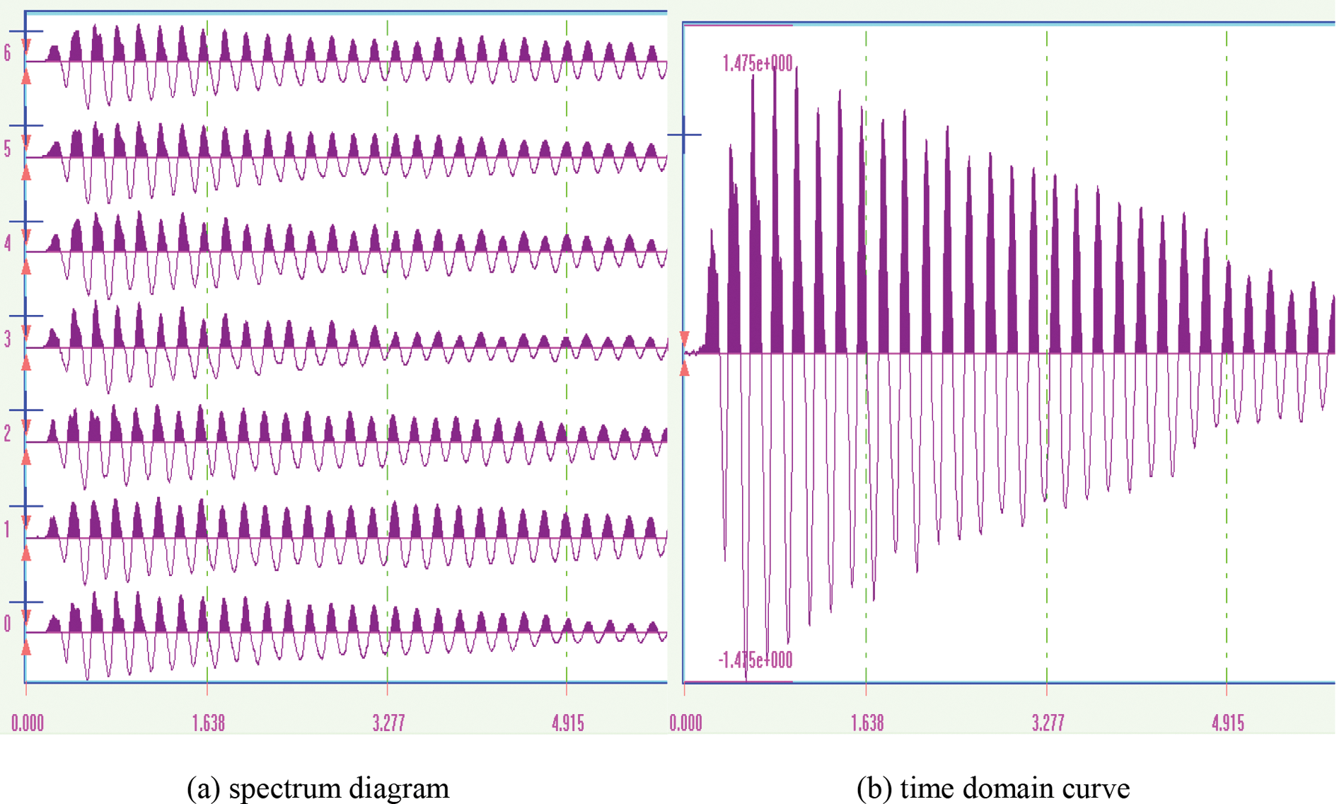
Figure 4: Spectrum diagram and time domain curve of S1–3 sample using impact-echo method
Results of the mass loss and the value of Pn and Pn2 of prismatic specimens after various cycles of freeze-thaw are shown in Tables 4–7. The Pn and Pn2 are the relative dynamic elastic modulus (RDEM, %) based on the transverse frequency and velocity of P-wave, respectively, which can be calculated by Eqs. (5) and (6): The mass loss ratio (W1, %) can be calculated by Eq. (7): where W0 is the initial mass of samples; Wn is the mass of sample after n-th cycles of freeze-thaw tests. Tables 4–7 show that the greatest mass loss of 1.07% was found after 50-th freeze-thaw cycles of S1. A low deformation of the longitudinal and transverse on samples was found during the freeze-thaw tests, so the size, Poisson ratio, and density of samples are considered as almost unchanged during tests.


Results of regression analysis based on the least square method between Ed and Vp1, Vp1 and f of four groups of prismatic specimens are presented in Table 8, which substantially conforms the relation of Vp1 = 1.843f. Ed is proportional to the square of Vp1, and all of regression analyses have a high correlation coefficient of larger than 0.99.

Results of Pn2 of the four groups of samples show a well correlation with that of Pn, as shown in Figs. 5 and 6. All the deviation ratios between the Pn2 and Pn are less than 5%, except for the S2 group (reaching 7.89% at 75-th cycles). In all groups, the Pn2 is slightly larger than Pn, indicating that the relative dynamic elastic modulus calculated by velocity of P-wave is larger than that calculated by the transverse frequency. Therefore, real-time detection of the velocity of P-wave of concrete can be used to monitor the change of relative dynamic elastic modulus of the actual structure [29–32], so as to analyze the degradation degree of concrete during freeze-thaw cycles.

Figure 5: Curves of relative dynamic elastic modulus (REDM) changed with freeze-thaw cycles for L1 and L2 specimens

Figure 6: Curves of relative dynamic elastic modulus (REDM) changed with freeze-thaw cycles for S1 and S2 specimens
The frost-resistance properties of L1 group is better than that of L2 group; Similarly, the frost-resistance properties of S1 group is better than that of S2 group, which reveals that using a smaller water-cement ratio is beneficial to improve the frost resistance of concrete. Lu et al. [33] also found that the lower the water-cement ratio, the stronger the ability to resist freeze-thaw cycles of ultra-high performance concrete. Freeze-thaw cycle tests were conducted by Zhao et al. [34] on concrete with different maximum particle sizes of coarse aggregates (9.5, 19, 26.5, 31.5, and 37.5 mm), and found that the relative dynamic elastic modulus decreased with the increase of the maximum particle size of coarse aggregates. The frost heave appeared on the coarse aggregate when the particle size exceeded 31.5 mm. Dalibor et al. [35] found that the relative dynamic elastic modulus decreased rapidly after the 50 cycles of freeze-thaw tests when the maximum particle size of coarse aggregates was within 16 mm (w/c ≥ 0.5), which is very similar to the test results of sample S2 in Fig. 6.
Both relative dynamic elastic modulus displayed a relatively mild decrease before 50-th cycles and showed a sharp decrease afterwards. The decrease in relative dynamic elastic modulus indicates that the damage has been appeared in internal structure, thereby reducing the compaction as well. The damage is accelerated in a relatively loose structure during the subsequent freeze-thaw cycles, extending the propagation time of elastic waves in concrete, which results in a sharper decrease in relative dynamic elastic modulus. For example, when the Pn < 60% (freeze-thaw cycles is ranging from 75-th to 100-th for LI and S1 groups, and 25-th to 50-th for L2 and S2 groups), the Vp1 of L1 group decreasd from 3376 to 2109 m/s, with a Vp3 decreasing from 3558 to 2223 m/s. Similarly, Vp3 of L1, L2, S1, and S2 groups decreased by 37.5%, 28.3%, 40.5%, and 40.0%, respectively. At this conditions, the value of Vp3 is lower than 3600 m/s, the general standard of concrete quality evaluation [36], indicating a serious internal damage of concrete caused by freeze-thaw cycles.
3.3 Size Effect of Impact-Echo Method
The port hydraulic structure has characteristics of various cross-section and a relatively large volume in actual engineering. For example, the front structure of the gravity wharf (breast wall, caisson, buttress, etc.) has various forms, and the cross-section has rectangular, circular, stepped, etc. [37,38]; In-service concrete structures need to be evaluated by inspection of their different structural elements to determine their durability [39–43]. Methodologies have been developed in different countries to estimate the health of structure through inspection [44–58].
The reinforced concrete structure is usually used to improve its strength, rigidity, and integrity. Therefore, various shapes and sizes of samples were designed to explore the size effect on the velocity of elastic wave, and the results can be found in Table 9. It indicates that the shape and size have scarcely influence on the velocity of elastic wave at a specific curing age, indicating that this method is suitable for the detecting of a physical engineering. The maximum deviation is just 2.1%, occurring between the cube samples and cuboid sample at 7 d of curing. The velocity of elastic wave shows an obvious increase during the early age and becomes level off afterwards. This trend is consistent with that of strength development due to the forming of a compacter microstructure of concrete as a function of the curing age.

3.4 Frost-Resistance Property of Various Cross-Section Size Samples Detected by Impact-Echo Method
Based on the results of the fact that the velocity of P-wave is independent of the shape and size of samples, the frost-resistance property of samples with various cross-section size was investigated and results are listed in Table 10. The decrease trends of velocity of P-wave and relative dynamic elastic modulus for the cross-section size of 100 and 150 mm is generally the same after 75-th freeze-thaw cycles, decreasing to 36.10% and 36.93% of the initial value, respectively. In comparison, the relative dynamic elastic modulus for the cross-section size of 200 and 250 mm decreases only to 78.40% and 80.66% of the initial value, respectively, indicating that the damage of larger cross-section size groups is far less than that of the smaller groups.

In addition, a larger volume sample with a dimension of 500 mm × 500 mm × 500 mm was prepared to further explore changes in the degree of freeze-thaw damage as a function of the section thickness. The schematic diagram of samples testing and measuring-point arrangement are shown in Figs. 7 and 3f, respectively, and results are shown in Fig. 8. Results show that the degree of damage can be obviously divided into three regions. For example, the relative dynamic elastic modulus can be divided into three ranges of 75%–80%, 85%–90%, and 90%–95% after 100-th freeze-thaw cycles, and the RDEM distribution diagram can be found in Fig. 9. It can be seen that the 75%–80% region is located at the four corners of the specimen, 85%–90% region is located at the remaining edges of the specimen, and 90%–95% region is located at the center of the specimen. The degree of erosion damage of the center of specimen is much slighter than that of the external rim regions.

Figure 7: Schematic diagram of samples testing (500 mm × 500 mm × 500 mm) using impact-echo method

Figure 8: RDEM obtained from different measuring points of prismatic concrete (500 mm × 500 mm × 500 mm) as a function of freeze-thaw cycles

Figure 9: RDEM distribution diagram of a 500 mm × 500 mm × 500 mm specimen with 100-th freeze-thaw cycles
It spends a longer period for the center of the cross-section to drop a same temperature as the cross-section size of samples increased, because the specific heat capacity of concrete remains unchanged during the processes of freeze-thaw cycles. This indicates that the decrease in the relative dynamic elastic modulus reduced from the surface to the inner layer; that is, the surface is expected to be the most vulnerable part for the freeze-thaw damage. The outside of concrete protects the inter part from the freeze-thaw damage; so if the size of the specimen is large enough, the internal concrete is likely not to be damaged during freeze-thaw cycles, just like the flowing water under the ice in winter.
3.5 Applicability Analysis of Impact-Echo Method for the Detecting of Frost-Resistance Property for On-Site Structures
In fact, the major freeze-thaw damage usually displays on the surface of hydraulic structure. The damage of accompanying samples conducted by the laboratory freeze-thaw cycles is much more serious than that of the practical structure. For example, many core samples have been damaged but the practical structure only showed honeycomb or pockmark. The laboratory samples have been subjected to 200 freeze-thaw cycles, but the practical structure on site may have only subjected to 125 times. Therefore, the laboratory freeze-thaw testing cannot reflect the damage of practical structure very well. The impact-echo method is suitable for on-site non-destructive testing of practical structure, and is expected to have a more widely application in detecting the frost-resistance property.
The velocity of P-wave of concrete is not greatly affected by the size effect. The impact-echo method has good accuracy and strong practicability, and can be used to evaluate the frost-resistance property of large-volume hydraulic concrete structures on site. A high-frequency monitoring is needed for the detecting of structural deformation, displacement, temperature, stress, or other parameters. However, a high-frequency monitoring is unnecessary when using the impact-echo method due to the relatively slow progress of concrete durability deterioration. The impact-echo method can be used to test the P-wave velocity of concrete every year or several years according to the importance of the structure and the degree of damage. The speed and trend for durability degradation of concrete can be fully obtained through the accumulation, analysis, and prediction of test data. This is of great significance to the detecting for frost-resistance property of large-volume hydraulic concrete.
Currently, according to the Chinese standard JTS304-2019, the detection method of freeze-resistance properties for on-site hydraulic concrete is that: After drilling the core sample on the surface of the concrete structure, the core sample is sawed and cut into two pieces, one of which has a surface affected by freezing and thawing, and the other is not affected by freezing and thawing. The rapid freeze and thaw cycle tests were carried out on these two core samples. The current freeze-thaw damage of the original structure and the remaining service life are estimated by comparison the two core samples. The disadvantage of this method is that it requires a “quick freezing” test, which is cumbersome and time-consuming. The frost resistance property of structure can be directly evaluated when using the impact-echo technology. The P-wave velocity of the two core samples is needed to be measured for the calculation of the relative dynamic elastic modulus. P-wave velocity tests are needed only on the surface of the structure when the structure is tested for durability again, which avoids coring again. One cycle of freeze-thaw test lasted 13–14 h and 2.5–3 h, respectively. After 100 cycles of freeze-thaw, the relative dynamic elastic moduli dropped to 10% and 90%, respectively, indicating that the large specimens have a better frost resistance property. The results of in-situ tests of the loss in relative dynamic elastic moduli during frost resistance tests of large-size structure is cannot be replaced by laboratory tests conducted on core samples. Therefore, the impact-echo technology cannot be replaced by the traditional resonance frequency method in detecting the frost resistance property of large-size concrete structures on-site.
Based on the above experimental results, the frost resistance of the structure in the actual project (the 300,000-ton crude oil terminal project in the Rongxing Port Area of Panjin Port) have been evaluated by using the impact-echo method. The thickness of a pier is 3 m with a design strength of 45 MPa, and a design level of freeze thaw durability of F350. The results show that the impact-echo method has a higher accuracy in evaluating the frost resistance of large-size hydraulic concrete compared to the ultrasonic method and resonance method. The impact-echo method has a high reliability proved by repeatability tests and reproducibility tests. It proves that the impact-echo technology has good applicability for on-site testing of the durability of concrete structures in water transportation projects.
The feasibility of the impact-echo method to obtain the relative dynamic elastic modulus is explored to detect the frost-resistance property of large-volume hydraulic concrete on site. A comparison between the impact-echo method and the traditional resonance frequency method in detecting the relative dynamic elastic modulus is also conducted. We make the following conclusions:
The impact-echo method can replace the traditional resonance frequency method to evaluate the frost resistance of concrete, and has advantages of high accuracy, easy to operate, and not limiting to the size of aggregates and samples. Thus, the impact-echo method can be used to evaluate the frost-resistance property of large-volume hydraulic structure on site by detecting the relative dynamic elastic modulus without drilling core, which is more convenient to operate than traditional resonance method. The dynamic elastic modulus of concrete detected by the impact-echo method has little difference with that obtained by the transverse resonance method. The deviation between the two methods is controlled within 2% for the dynamic modulus of elasticity, and within 5% for the relative dynamic elastic modulus of elasticity. The one-dimensional P-wave velocity of concrete has a good linear correlation with the transverse resonance frequency, which substantially conforms the Vp1 = 1.843f. Ed is proportional to the square of Vp1, and all of regression analyses have a high correlation coefficient of larger than 0.99.
The velocity of P-wave of concrete is not greatly affected by the size effect, while the frost resistance of concrete is greatly affected by the size effect. A reduction of the water-cement ratio is beneficial to improve the frost resistance of concrete. The freeze-thaw damage develops from the surface to the inner layer, and the surface is expected to be the most vulnerable part for the freeze-thaw damage. For example, the relative dynamic elastic modulus decreases to 36% of the initial value when the side length of samples is not greater than 150 mm. For the large-size concrete specimens, the relative dynamic elastic modulus of samples with side lengths of 200 and 250 mm are 78% and 81% of the initial value. The relative dynamic elastic modulus of the edge position of concrete is 13% lower than that in the central position. It is expected to monitor and track the degradation of the frost resistance of the actual structure by frequently detecting the P-wave velocity on site.
Funding Statement: This work was financed by Hainan Provincial Natural Science Foundation of China (522QN279) and the Research Lab Construction of Hainan University (ZY2019HN0904).
Conflicts of Interest: The authors declare that they have no conflicts of interest to report regarding the present. study.
References
1. Mehta, P. K. (1991). Durability of concrete-fifty years of progress. Proceedings of the 2nd International Conference on Durability of Concrete, Detroit, USA. [Google Scholar]
2. Zhao, X., Lv, X., Wang, L., Zhu, Y., Dong, H. et al. (2015). Research of concrete residual strains monitoring based on WLI and FBG following exposure to freeze-thaw tests. Cold Regions Science and Technology, 116, 40–48. https://doi.org/10.1016/j.coldregions.2015.04.007 [Google Scholar] [CrossRef]
3. Wu, Y., Hubbard, S. S., Ulrich, C., Wullschleger, S. D. (2013). Remote monitoring of freeze-thaw transitions in Arctic soils using the complex resistivity method. Vadose Zone Journal, 12(1), 1–13. https://doi.org/10.2136/vzj2011.0176 [Google Scholar] [CrossRef]
4. Arnfelt, H. (1943). Damage on concrete pavements by winter time salt treatment. Statens Vaeginst (Sweden). [Google Scholar]
5. Skripkiūnas, G., Nagrockienė, D., Girskas, G., Vaičienė, M., Baranauskaitė, E. (2013). The cement type effect on freeze-thaw and deicing salt resistance of concrete. Procedia Engineering, 57, 1045–1051. https://doi.org/10.1016/j.proeng.2013.04.132 [Google Scholar] [CrossRef]
6. Wang, L., Cao, Y., Wang, Z., Du, P. (2013). Evolution and characterization of damage of concrete under freeze-thaw cycles. Journal of Wuhan University of Technology-Materials Science Edition, 28(4), 710–714. https://doi.org/10.1007/s11595-013-0757-7 [Google Scholar] [CrossRef]
7. Cao, J. G., Li, J. Y., Lin, L., Tian, J. T., Guan, Y. S. et al. (1999). Study on frost-resistance of high-strength concrete. Journal of Building Materials, 2(4), 292–297. [Google Scholar]
8. Powers, T. C. (1938). Measuring young’s modulus of elasticity by means of sonic vibrations. Proceedings of American Society of Testing Materials, 38, 460–469. [Google Scholar]
9. Su, H., Lin, W. Z. (2003). Impact-echo method and ITS application to civil engineering. Nondestructive Testing, 26(3), 81–83 (in Chinese). [Google Scholar]
10. ASTM C1383 (2000). Test method for measuring the P-wave speed and the thickness of concrete plates using the impact-echo method. USA: American Society of Testing Materials. [Google Scholar]
11. ASTM C125 (2008). Standard test method for fundamental transverse, longitudinal, and torsional resonant frequencies of concrete specimens. USA. [Google Scholar]
12. Liang, M. T., Su, P. J. (2001). Detection of the corrosion damage of rebar in concrete using impact-echo method. Cement and Concrete Research, 31, 1427–1436. https://doi.org/10.1016/S0008-8846(01)00569-5 [Google Scholar] [CrossRef]
13. Krzemień, K., Hager, I. (2015). Post-fire assessment of mechanical properties of concrete with the use of the impact-echo method. Construction and Building Materials, 96, 155–163. https://doi.org/10.1016/j.conbuildmat.2015.08.007 [Google Scholar] [CrossRef]
14. Azari, H., Nazarian, S., Yuan, D. (2014). Assessing sensitivity of impact echo and ultrasonic surface waves methods for nondestructive evaluation of concrete structures. Construction and Building Materials, 71, 384–391. https://doi.org/10.1016/j.conbuildmat.2014.08.056 [Google Scholar] [CrossRef]
15. Chaudhary, M. T. A. (2013). Effectiveness of impact echo testing in detecting flaws in prestressed concrete slabs. Construction and Building Materials, 47, 753–759. https://doi.org/10.1016/j.conbuildmat.2013.05.021 [Google Scholar] [CrossRef]
16. Hsu, K. T., Cheng, C. C., Lin, Y. (2008). Use impact-echo method to evaluate bond of reinforced concrete subjected to early-age vibration. Journal of Solid Mechanics and Materials Engineering, 2(12), 1528–1538. https://doi.org/10.1299/jmmp.2.1528 [Google Scholar] [CrossRef]
17. Zima, B. (2019). Guided wave propagation in detection of partial circumferential debonding in concrete structures. Sensors, 19, 1–19. https://doi.org/10.3390/s19092199 [Google Scholar] [PubMed] [CrossRef]
18. Wandowski, T., Kudela, P., Ostachowicz, W. M. (2019). Numerical analysis of elastic wave mode conversion on discontinuities. Composite Structures, 215, 317–330. https://doi.org/10.1016/j.compstruct.2019.02.076 [Google Scholar] [CrossRef]
19. Jaganathan, A. P. (2019). Multichannel surface wave analysis of reinforced concrete pipe segments using longitudinal and circu mferential waves induced by a point impact. Journal of Applied Geophysics, 163, 40–54. https://doi.org/10.1016/j.jappgeo.2019.02.010 [Google Scholar] [CrossRef]
20. Hamid, G. A. (2008). Long-term bridge performance program. Fourth US-Taiwan Bridge Engineering Workshop. [Google Scholar]
21. Wang, W., Lu, C., Yuan, G., Zhang, Y. (2017). Effects of pore water saturation on the mechanical properties of fly ash concrete. Construction and Building Materials, 130, 54–63. https://doi.org/10.1016/j.conbuildmat.2016.11.031 [Google Scholar] [CrossRef]
22. Dvoák, R., Topolá, L. (2021). Effect of hammer type on generated mechanical signals in impact-echo testing. Materials, 14, 606–624. https://doi.org/10.3390/ma14030606 [Google Scholar] [PubMed] [CrossRef]
23. SL352-2020 (2021). Test code for hydraulic concrete. Beijing, China: China Water & Power Press. [Google Scholar]
24. JTS/T 236-2019 (2019). Technical specification for concrete testing of port waterway engineering. Beijing, China: China Communications Press Co., Ltd. [Google Scholar]
25. Lu, X., Sun, Q., Feng, W., Tian, J. (2013). Evaluation of dynamic modulus of elasticity of concrete using impact-echo method. Construction and Building Materials, 47, 231–239. https://doi.org/10.1016/j.conbuildmat.2013.04.043 [Google Scholar] [CrossRef]
26. Kee, S. H., Lee, J. W., Candelaria, M. D. (2020). Evaluation of delamination in concrete by ie testing using multi-channel elastic wave data. Sensors, 20, 201–220. [Google Scholar]
27. Wu, X., Yan, Q., Hedayat, A., Wang, X. (2021). The influence law of concrete aggregate particle size on acoustic emission wave attenuation. Scientific Reports, 11(1), 1–14. https://doi.org/10.1038/s41598-021-02234-x [Google Scholar] [PubMed] [CrossRef]
28. Lu, X., Ma, F., Luke, A., Wang, R. (2015). Assessing frost resistance of concrete by impact-echo method. Magazine of Concrete Research, 67, 317–324. https://doi.org/10.1680/macr.14.00051 [Google Scholar] [CrossRef]
29. Lin, J., Sansalone, M. (1997). A procedure for determining P-wave speed in concrete for use in impact echo testing using a Rayleigh wave speed measurement technique. Innovations in Nondestructive Testing of Concrete, 168, 137–166. [Google Scholar]
30. Sansalone, M., Carino, N. J. (1986). Impact-echo: A method for flaw detection in concrete using transient stress waves. National Bureau of Standards. [Google Scholar]
31. Cheng, C., Sansalone, M. (1995). Determining the minimum creak width that can be detected using the impact-echo method Part 1: Experimental study. Materials and Structures, 28, 74–82. https://doi.org/10.1007/BF02473174 [Google Scholar] [CrossRef]
32. Hsiao, C., Cheng, C. C., Liou, T., Juang, Y. (2008). Detecting flaws in concrete blocks using the impact-echo method. NDT & E International, 41, 98–107. [Google Scholar]
33. Lu, Z., Feng, Z., Yao, D., Li, X., Ji, H. (2021). Freeze-thaw resistance of ultra-high performance concrete: Dependence on concrete composition. Construction and Building Materials, 293, 123523–123532. https://doi.org/10.1016/j.conbuildmat.2021.123523 [Google Scholar] [CrossRef]
34. Zhao, S., Xia, J. (2011). Durability based indexes of coarse aggregate for cement concrete. Advanced Materials Reasearch, 31, 1941–1946. https://doi.org/10.4028/www.scientific.net/AMR.250-253.1941 [Google Scholar] [CrossRef]
35. Dalibor, K., Tomáš, V., Barbara, K. (2018). Influence of coarse aggregate grain size on frost resistance of concrete. Rehabilitation and Reconstruction of Buildings, 776, 37–40. [Google Scholar]
36. Leslie, J. R., Cheeseman, W. J. (1949). An ultrasonic method for studying deterioration and creaking in concrete structures. American Concrete Institute Proceedings, 46, 17–36. [Google Scholar]
37. Pirooznia, A., Moradloo, A. J. (2020). Investigation of size effect and smeared crack models in ordinary and dam concrete fracture tests. Engineering Fracture Mechanics, 226(1), 106863–106887. https://doi.org/10.1016/j.engfracmech.2019.106863 [Google Scholar] [CrossRef]
38. Huang, Y., Xiao, L., Gao, J., Liu, Y. (2019). Tensile creep and unloading creep recovery testing of dam concrete with fly ash. Journal of Materials in Civil Engineering, 31(5), 05019001.1–05019001.7. https://doi.org/10.1061/(ASCE)MT.1943-5533.0002682 [Google Scholar] [CrossRef]
39. Xiao, M., Zhang, S., Tang, Y., Lin, Z., Chen, J. (2016). A study of a real-time online monitoring system for the durability of concrete structures. Anti-Corrosion Methods & Materials, 63(3), 184–189. https://doi.org/10.1108/ACMM-11-2015-1608 [Google Scholar] [CrossRef]
40. Fang, X., Yin, Z., Chen, H., Ni, J., Zhang, D. et al. (2021). Comparison study on durability monitoring and inspection for reinforced concrete structure in marine environment. The Ocean Engineering, 39(6), 111–118. [Google Scholar]
41. Yang, H., Hu, Z., Yu, F., Fang, Z. (2019). Field test and evaluation analysis on durability of fly ash concrete structures in seawater environment. The Ocean Engineering, 37(2), 104–111. [Google Scholar]
42. Chalee1, W., Cheewaket1, T., Jaturapitakkul, C. (2021). Utilization of recycled aggregate concrete for marine site based on 7-year field monitoring. International Journal of Concrete Structures and Materials, 15, 34–44. https://doi.org/10.1186/s40069-021-00473-w [Google Scholar] [CrossRef]
43. Torres-Acosta, A. A., Patron-Solares, A., Alcantara-Lagunes, P. (2020). Durability health monitoring during construction of concrete structures in marine environment. Structural Control and Health Monitoring, 28(3), e2674–e2675. [Google Scholar]
44. Madani, H. M., Dolatshahi, K. M. (2020). Strength and stiffness estimation of damaged reinforced concrete shear walls using crack patterns. Structural Control and Health Monitoring, 7(4), e2494.1–e.2494.18. https://doi.org/10.1002/stc.2494 [Google Scholar] [CrossRef]
45. Raja, B. N. K., Miramini, S., Duffield, C., Sofi, M., Mendis, P. et al. (2020). The influence of ambient environmental conditions in detecting bridge concrete deck delamination using infrared thermography (IRT). Structural Control and Health Monitoring, 27(4), e2506–e2521. https://doi.org/10.1002/stc.2506 [Google Scholar] [CrossRef]
46. An, Y., Chatzi, E., Sim, S. H., Laflamme, S., Blachowski, B. (2019). Recent progress and future trends on damage identification methods for bridge structures. Structural Control and Health Monitoring, 26(10), e2416–e2445. https://doi.org/10.1002/stc.2416 [Google Scholar] [CrossRef]
47. Yang, C., Li, L., Li, J. (2020). Service life of reinforced concrete seawalls suffering from chloride attack: Theoretical modelling and analysis. Construction and Building Materials, 263(4), 120172–120185. https://doi.org/10.1016/j.conbuildmat.2020.120172 [Google Scholar] [CrossRef]
48. Jin, M., Ma, Y., Zeng, H., Liu, J., Gu, Y. (2020). Developing a multi-element sensor to non-destructively monitor several fundamental parameters related to concrete durability. Sensors, 20(19), 5607–5634. https://doi.org/10.3390/s20195607 [Google Scholar] [PubMed] [CrossRef]
49. Wei, B., Liu, B., Yuan, D., Mao, Y., Yao, S. (2021). Spatiotemporal hybrid model for concrete arch dam deformation monitoring considering chaotic effect of residual series. Engineering Structures, 228(1), 111488–111501. https://doi.org/10.1016/j.engstruct.2020.111488 [Google Scholar] [CrossRef]
50. Zima, B., Kdra, R. (2020). Baseline-free debonding detection in reinforced concrete structures by elastic wave propagation. Measurement, 172, 108907–108921. https://doi.org/10.1016/j.measurement.2020.108907 [Google Scholar] [CrossRef]
51. Li, D., Yang, K., He, Z., Zhou, H., Li, J. (2020). Acoustic emission wave velocity attenuation of concrete and its application in crack localization. Sustainability, 12(8), 7405–7418. https://doi.org/10.3390/su12187405 [Google Scholar] [CrossRef]
52. Liu, Z., Ma, C., Wei, X. (2021). P-wave velocity and energy evolution process of concrete in uniaxial loading-unloading tests. Journal of Materials in Civil Engineering, 33(6), 04021110.1–04021110.10. 10.1061/(ASCE)MT.1943-5533.0003723 [Google Scholar] [CrossRef]
53. Kang, F., Li, J., Zhao, S., Wang, Y. (2019). Structural health monitoring of concrete dams using long-term air temperature for thermal effect simulation. Engineering Structures, 180(2), 642–653. https://doi.org/10.1016/j.engstruct.2018.11.065 [Google Scholar] [CrossRef]
54. Basu, S., Thirumalaiselvi, A., Sasmal, S., Kundu, T. (2021). Nonlinear ultrasonics-based technique for monitoring damage progression in reinforced concrete structures. Ultrasonics, 115, 106472–106484. https://doi.org/10.1016/j.ultras.2021.106472 [Google Scholar] [PubMed] [CrossRef]
55. Wang, Z., Markham, A. (2020). Wirelessly powered embedded sensor nodes for internal structural health monitoring. IEEE Transactions on Industrial Electronics, (99), 3013536–3013544. [Google Scholar]
56. Heitner, B., Obrien, E. J., Yalamas, T., Schoefs, F., Leahy, C. et al. (2019). Updating probabilities of bridge reinforcement corrosion using health monitoring data. Engineering Structures, 190(7), 41–51. https://doi.org/10.1016/j.engstruct.2019.03.103 [Google Scholar] [CrossRef]
57. Kang, F., Li, J., Dai, J. (2019). Prediction of long-term temperature effect in structural health monitoring of concrete dams using support vector machines with Jaya optimizer and salp swarm algorithms. Advances in Engineering Software, 131, 60–76. https://doi.org/10.1016/j.advengsoft.2019.03.003 [Google Scholar] [CrossRef]
58. Wang, C., Xiao, J., Zhang, C., Xiao, X. (2020). Structural health monitoring and performance analysis of a 12-story recycled aggregate concrete structure. Engineering Structures, 205, 110102.1–110102.18. https://doi.org/10.1016/j.engstruct.2019.110102 [Google Scholar] [CrossRef]
Cite This Article
 Copyright © 2023 The Author(s). Published by Tech Science Press.
This work is licensed under a Creative Commons Attribution 4.0 International License , which permits unrestricted use, distribution, and reproduction in any medium, provided the original work is properly cited.
 Downloads
 Citation Tools