
 Submit a Paper
 Propose a Special lssue
 Open Access
ARTICLE

Numerical Analysis of Cold-Formed Thin-Walled Steel Short Columns with Pitting Corrosion during Bridge Construction
1 CCCC Second Harbor Engineering Third Engineering Co., Ltd., Zhenjiang, 212000, China
2 Suqian Highway Development Center, Suqian, 223800, China
3 School of Mechanics and Civil Engineering, China University of Mining and Technology, Xuzhou, 221116, China
* Corresponding Author: Jing Chen. Email:
(This article belongs to the Special Issue: Health Monitoring and Rapid Evaluation of Infrastructures)
Structural Durability & Health Monitoring 2024, 18(2), 181-196. https://doi.org/10.32604/sdhm.2024.044628
Received 04 August 2023; Accepted 27 December 2023; Issue published 22 March 2024
 View Full Text
 Download PDF
Abstract
Pitting corrosion is harmful during bridge construction, which will lead to uneven roughness of steel surfaces and reduce the thickness of steel. Hence, the effect of pitting corrosion on the mechanical properties of cold-formed thin-walled steel stub columns is studied, and the empirical formulas are established through regression fitting to predict the ultimate load of web and flange under pitting corrosion. In detail, the failure modes and load-displacement curves of specimens with different locations, area ratios, and depths are obtained through a large number of non-linear finite element analysis. As for the specimens with pitting corrosion on the web, all the specimens are subject to local buckling failure, and the failure mode will not change with pitting corrosion, but the failure location will change with pitting corrosion location; the size, location, and area ratio of pitting corrosion have little influence on the ultimate load of cold-formed thin-walled steel short columns, but the loss rate of pitting corrosion section area has a greater impact on the ultimate bearing capacity. As for the specimen with flange pitting corrosion, the location and area ratio of pitting corrosion have less influence on the ultimate load of cold-formed thin-walled steel short columns, and the section area loss rate has greater influence on the ultimate bearing capacity; the impact of web pitting corrosion on the ultimate load is greater than that of flange pitting corrosion under the same condition of pitting corrosion section area. The prediction formulas of limit load which are suitable for pitting corrosion of web and flange are established, which can provide a reference for performance evaluation of corroded cold-formed thin-walled steel.Graphic Abstract
Keywords
Nomenclature
| d | Pitting diameter |
| h | Pit depth |
| | Loss rate of cross-sectional area |
| | Limit displacement |
| Pu | Ultimate load |
| | Ultimate load degradation coefficient |
In recent years, due to good strength and flexible section form, cold-formed thin-walled steel sections hafve been widely used as the load-bearing components during bridge construction [1–3]. The steel strip or steel plate is subject to plastic deformation after cold processing, which increases its yield and ultimate strength but reduces its deformation capacity. Therefore, the mechanical properties of cold-formed thin-walled steel are different from those of hot-rolled steel before forming [4,5]. Corrosion is one of the most important factors affecting the durability of steel structures, which will lead to uneven roughness of steel surfaces and reduce the thickness of steel [6–10]. Because the cold-formed thin-walled steel is thin, the effect of corrosion is more serious, so it is necessary to study the mechanical properties of corroded cold-formed thin-walled steel.
Corrosion is mainly divided into uniform corrosion and pitting corrosion. Uniform corrosion refers to the uniform reduction of steel plate thickness in the whole section. Many studies have revealed the effect of uniform corrosion on the mechanical properties of steel [11–14]. However, due to the roughness of pitting corrosion surface, it is difficult to simulate the real characteristics of pitting corrosion. Therefore, the simplest method is to equivalent pitting corrosion to the reduction of uniform thickness [15–17]. A practical and reliable method is that the complex pitting corrosion pits are replaced by regular patterns (cone, sphere, cylindrical) distributed on the steel surface [18–20]. In addition, the effect of pitting corrosion on the mechanical properties of hot-rolled steel plates has been extensively studied, including axial compression ultimate strength, transverse torsional buckling, local plane buckling, and tensile strength [21–24]. However, all the studies above are aimed at hot-rolled steel, and the effect of pitting corrosion on cold-formed thin-walled steel has not been reported.
In this paper, the effect of pitting corrosion on cold-formed thin-walled steel stub columns under axial compression is studied through finite element simulation. Considering the different effects of pitting corrosion of web and flange, a finite element analysis is carried out, and the failure modes and load-displacement curves of various specimens are obtained. The effects of pitting corrosion size, area ratio, location, and depth on cold-formed thin-walled steel stub columns are analyzed. Finally, empirical prediction formulas for the ultimate load of web and flange pitting corrosion are established, respectively.
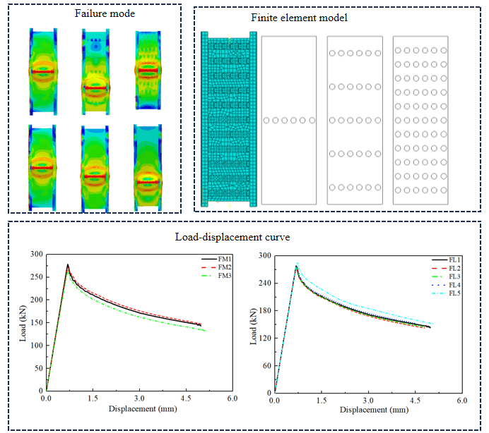
Finite element software Abaqus was used to simulate the effect of pitting corrosion on the mechanical properties of cold-formed thin-walled steel stub columns under axial compression. In order to satisfy the requirements of local buckling, the sizes of web, flange, crimp width, thickness and length of test pieces are 160, 80, 20, 2.9, and 500 mm, respectively. The quadrilateral shell element with four nodes is adopted, and the element size is 10 mm times 10 mm after a certain number of mesh sensitivity analyses. As for material properties, the initial defects and boundary conditions were carried out by referring to the reference [19]. Pitting corrosion is assumed to be regularly distributed, as shown in Fig. 1.
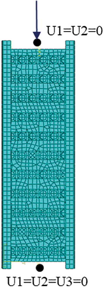
Figure 1: Finite element model
Because this paper mainly focuses on the effect of pitting corrosion, the residual stress and the strength improvement at the corner are not considered. The eigenvalue buckling analysis is firstly performed, and then the arc-length method is used for nonlinear buckling analysis. The simulation results show that the simulated ultimate load (338.91 kN) is bigger than the test ultimate bearing capacity (302.41 kN) for the rustless specimen, and the reason may be that the size of the test specimen is slightly smaller than the size of the simulated specimen.
3 Pitting Corrosion of Web Plate
Table 1 and Fig. 2 show the distribution of pitting corrosion and the loss rate of section area of the cold-formed thin-walled steel stub column for the case of web pitting corrosion, where the loss rate of section area refers to the ratio of the corroded section area to the original section area.
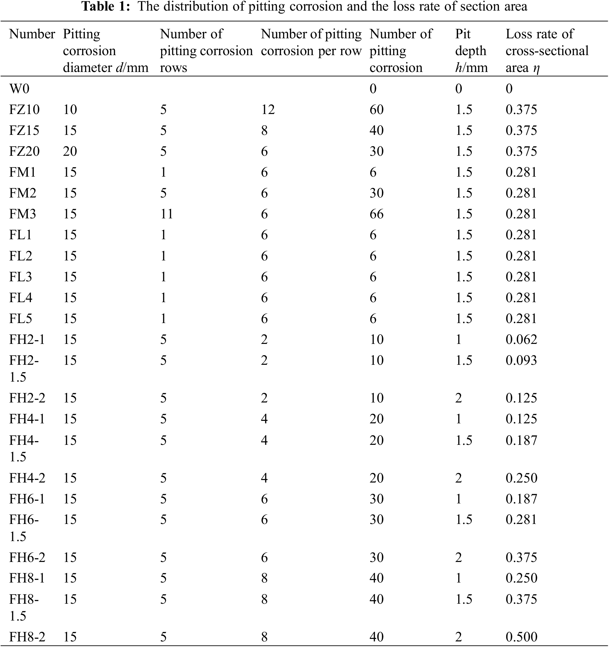
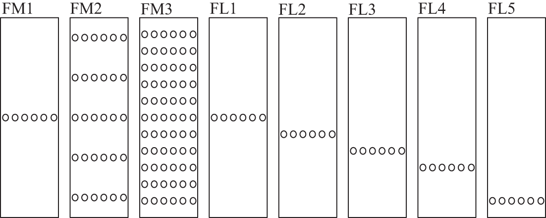
Figure 2: Distribution of web pitting corrosion
3.1 Effect of Web Pitting Corrosion Diameter
Three types of pitting corrosion diameters are considered, which are 10, 15, and 20 mm, respectively. These three diameters correspond to test pieces FZ10, FZ15, and FZ20, where F denotes the web, Z denotes the pitting diameter. The distribution of pitting corrosion is similar to the distribution of FM2, but each row is arranged with 12, 8, and 6 pitting corrosion respectively to ensure the same loss rate of sectional area. The depths of pitting corrosion are 1.5 mm. Figs. 3 and 4 show the failure modes and load-displacement curves corresponding to different pitting corrosion diameters. It can be seen that the failure modes of the specimens with different pitting corrosion diameters are the same, the failure displacement and load-displacement curve are close, which shows that the pitting corrosion diameter has little effect on the mechanical properties of corroded cold-formed thin-walled steel short columns.
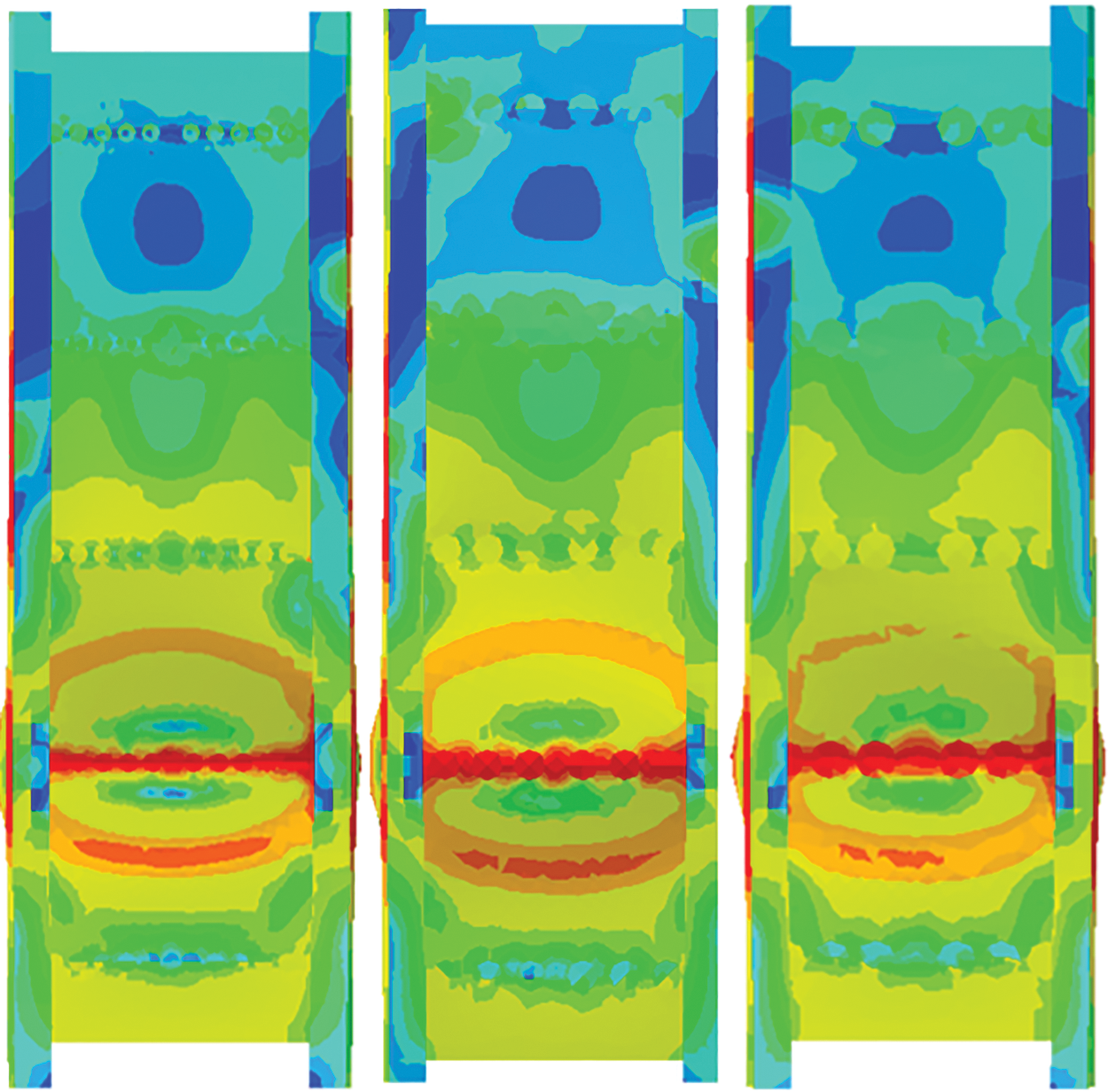
Figure 3: Failure mode of web with different pitting corrosion diameters
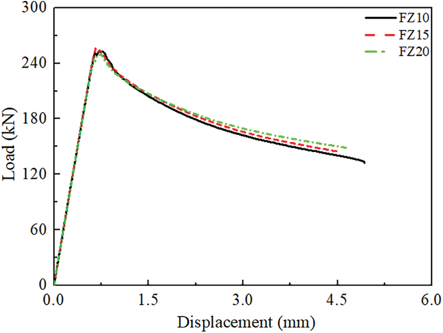
Figure 4: Load-displacement curve of web with different pitting corrosion diameters
3.2 Effect of Area Ratio of Web Pitting Corrosion
The ratio of web pitting corrosion area to web area is defined as area ratio of web pitting corrosion. Three area ratios of pitting corrosion are considered, which are 0.013, 0.066, and 0.155, respectively. The diameter and depth of pitting corrosion are 15 and 1.5 mm, respectively. The distribution of pitting corrosion refers to Fig. 2. The failure modes and load-displacement curves corresponding to different area ratios are shown in Figs. 5 and 6, respectively. It can be seen that the specimens with different area ratios have local buckling failure, the failure location is different and the failure occurs in the pitting corrosion section. It can be seen from Fig. 6 that the shapes of corrosion areas are similar, but the pitting corrosion makes the bearing capacity significantly decrease. When the pitting corrosion area ratio is 0.013, 0.066, and 0.155, the limit load decreases by 17.9%, 19.7%, and 21.6%, respectively, which indicates that the limit load decreases slightly with the increase of pitting corrosion area ratio, so it can be explained that the pitting corrosion area ratio has a small impact on the limit load.
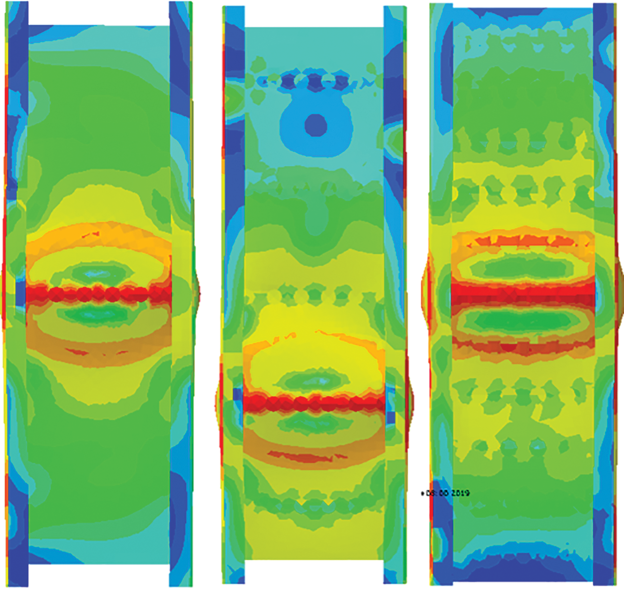
Figure 5: Failure mode of web with different area ratios
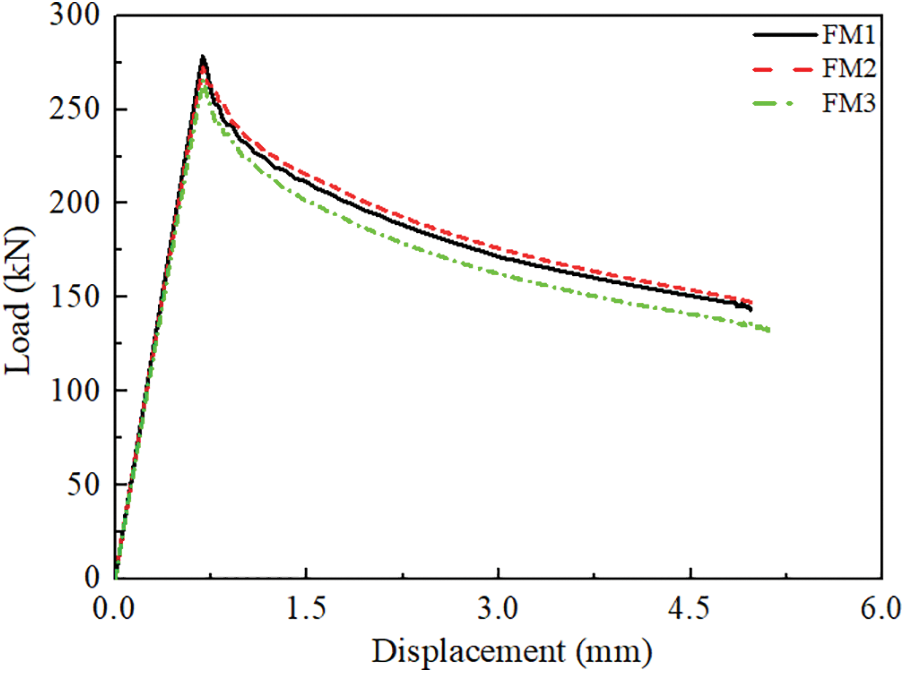
Figure 6: Load-displacement curves with different area ratios
3.3 Effect of Web Pitting Corrosion Location
Five cases of pitting corrosion locations are considered. The diameter and depth of pitting corrosion are 15 and 1.5 mm, respectively. The distribution of pitting corrosion refers to Fig. 2. The failure modes and load-displacement curves of specimens at different pitting corrosion locations are shown in Figs. 7 and 8. It can be found that the specimens at different pitting corrosion locations are subject to local buckling failure, and the failure location occurs at the pitting corrosion section. However, the specimen FL5 is different, and the pitting corrosion section does not bulge to the crimp. The possible reason is that the pitting corrosion section is close to the base, hence making the pitting corrosion section unable to bulge to the crimp. It can be seen from Fig. 8 that the load-displacement curves of other locations are similar except for the test piece FL5. The reason why the load of the test piece FL5 is higher than the others is that the pitting corrosion section is constrained by the base. The analysis shows that the pitting corrosion locations which are not close to the base will not significantly affect the bearing capacity of cold-formed thin-walled steel.
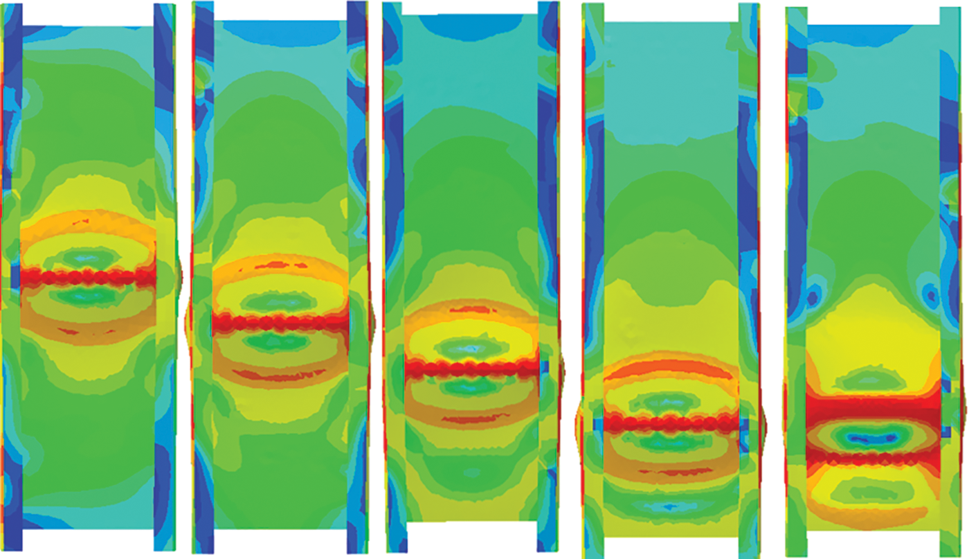
Figure 7: Failure mode of web at different pitting corrosion positions
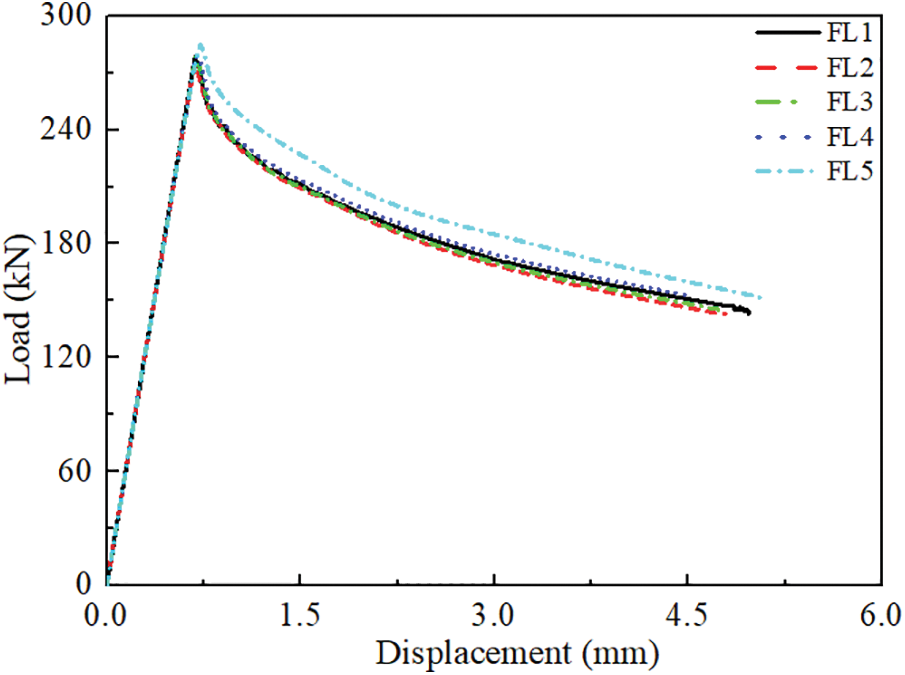
Figure 8: Load-displacement curve at different pitting corrosion positions of web
3.4 Effect of Web Pitting Corrosion Depth
Three types of pitting corrosion depth are considered, which are 1, 1.5, and 2 mm, respectively. The distribution of pitting corrosion is similar to FM2, but 2, 4, 6, and 8 pits are arranged in each row with a pitting corrosion diameter of 15 mm. Fig. 9 and Table 2 show the load-displacement curves and the simulation results of different depths, respectively. With regard to FHi-j, F denotes the web, H denotes the pitting corrosion depth, i denotes the number of pitting corrosion in each row, and j denotes the value of pitting corrosion depth. It can be seen from Fig. 9 that the load-displacement curve is similar for the same number of pitting corrosion specimens, but the load decreases continuously with the increase of pitting corrosion depth, and the load decreases more obviously with the increase of the number of pitting corrosion in each row.
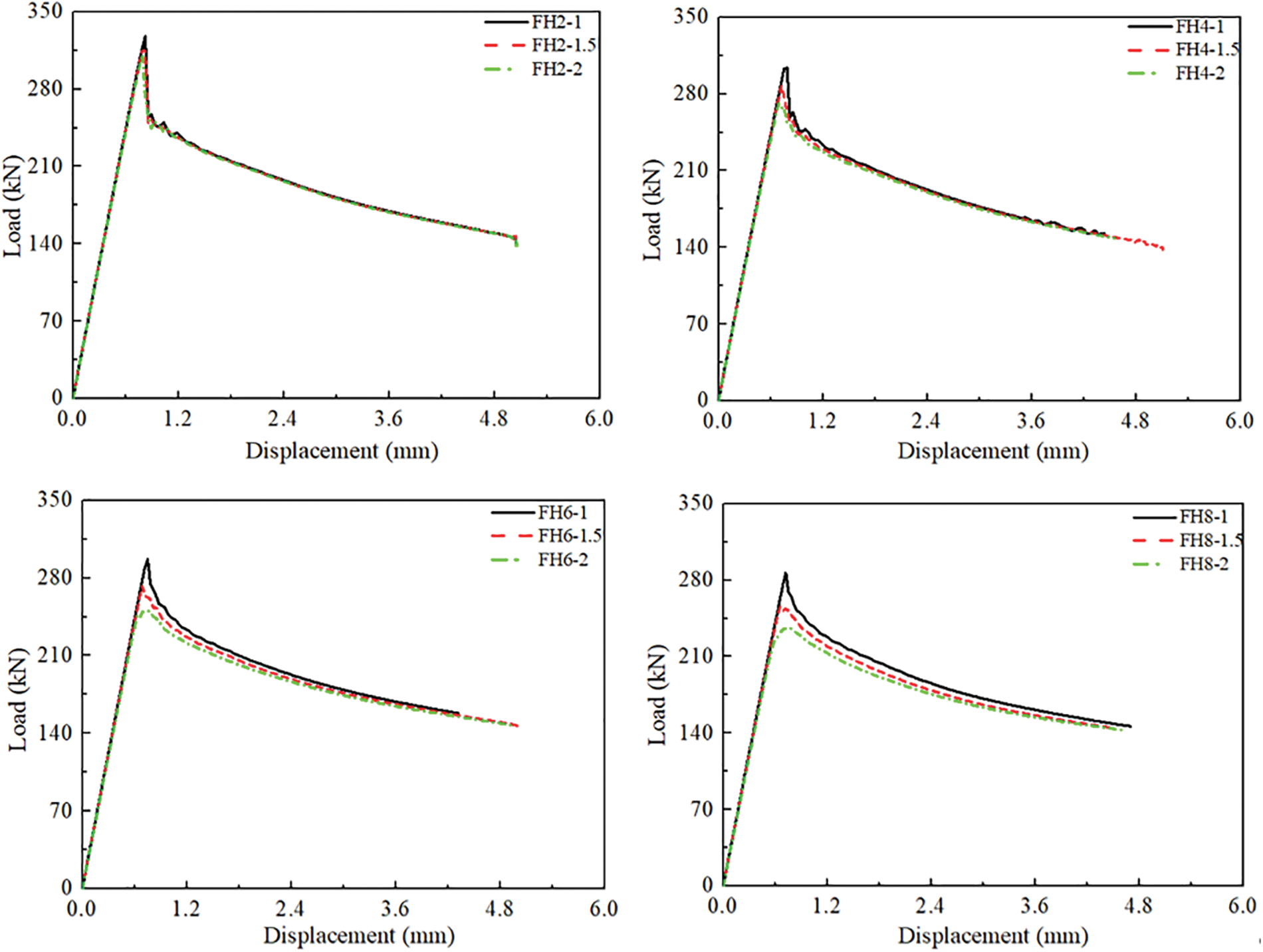
Figure 9: Load-displacement curve of web at different pitting corrosion depth
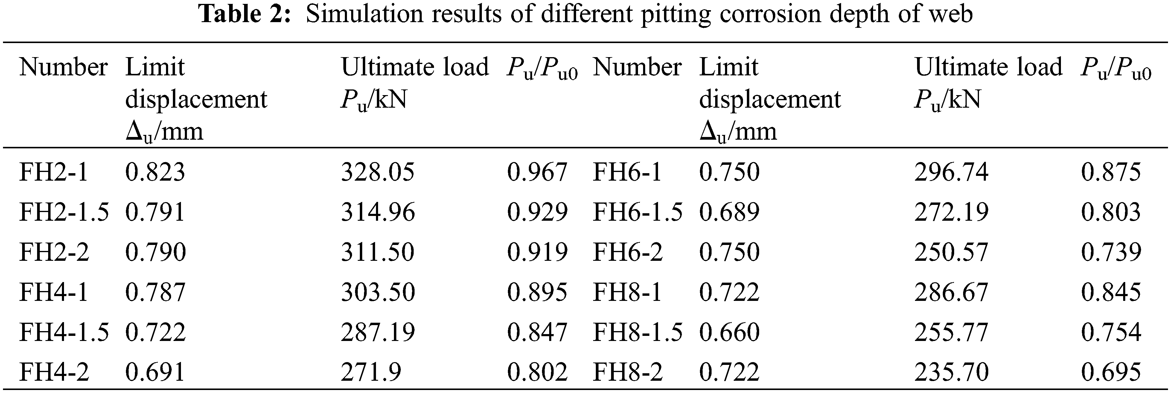
It can be seen from Table 2 that the ultimate load of FH2 is 328.05 kN when the pitting corrosion depth is 1 mm, and the ultimate load decreases to 314.96 and 311.50 kN respectively after the pitting corrosion depth is increased to 1.5 and 2 mm, indicating that the ultimate load of FH2 decreases continuously with the increase of pitting corrosion depth, and FH4, FH6 and FH8 have the same rules. It can also be seen that for FH2 and FH4 the limit displacement decreases with the increase of pitting corrosion depth; for FH6 and FH8, the limit displacement first increases and then decreases with the increase of pitting corrosion depth. The reason is that pitting corrosion will cause the specimen to be damaged in advance and pitting corrosion will reduce the cross-sectional area and increase the deformation.
3.5 Prediction of Web Pitting Corrosion Limit Load
From the analysis above, it can be seen that when the web is pitted, the diameter, area ratio, and location of pitting corrosion have a small impact on the ultimate bearing capacity, and the depth of pitting corrosion and the number of pitting corrosion on the same section have a large impact on the ultimate bearing capacity. The failure mode is a local buckling failure, but the failure location is different and mainly occurs in the pitting corrosion section. The reason is that the local buckling failure of the uncorroded specimen shows that the web of the specimen is weaker than the flange and crimp, and the web pitting corrosion makes the web weaker, so local buckling is more likely to occur. Further analysis shows that the main factor affecting the damage of pitting corrosion cold-formed thin-walled steel is the minimum section area, so the loss rate of sectional area is introduced.
Fig. 10 shows the correlation between the loss rate of sectional area and the ultimate load degradation coefficient, where the degradation coefficient refers to the ratio of the ultimate bearing capacity of the pitting corrosion test piece to the ultimate bearing capacity of the stainless steel. It can be seen that the correlation is approximately linear, which is expressed as follows:
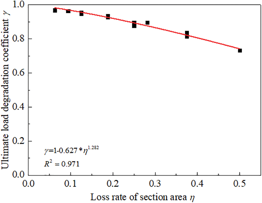
Figure 10: Correlation between the degradation coefficient and the loss rate
where,
In this study, pitting corrosion is symmetrically arranged on both sides of the flange, and the influence of pitting corrosion on one side of the flange is not considered. Table 3 and Fig. 11 show the pitting corrosion distribution and section area loss rate of the cold-formed thin-walled steel stub column flange pitting corrosion test piece.
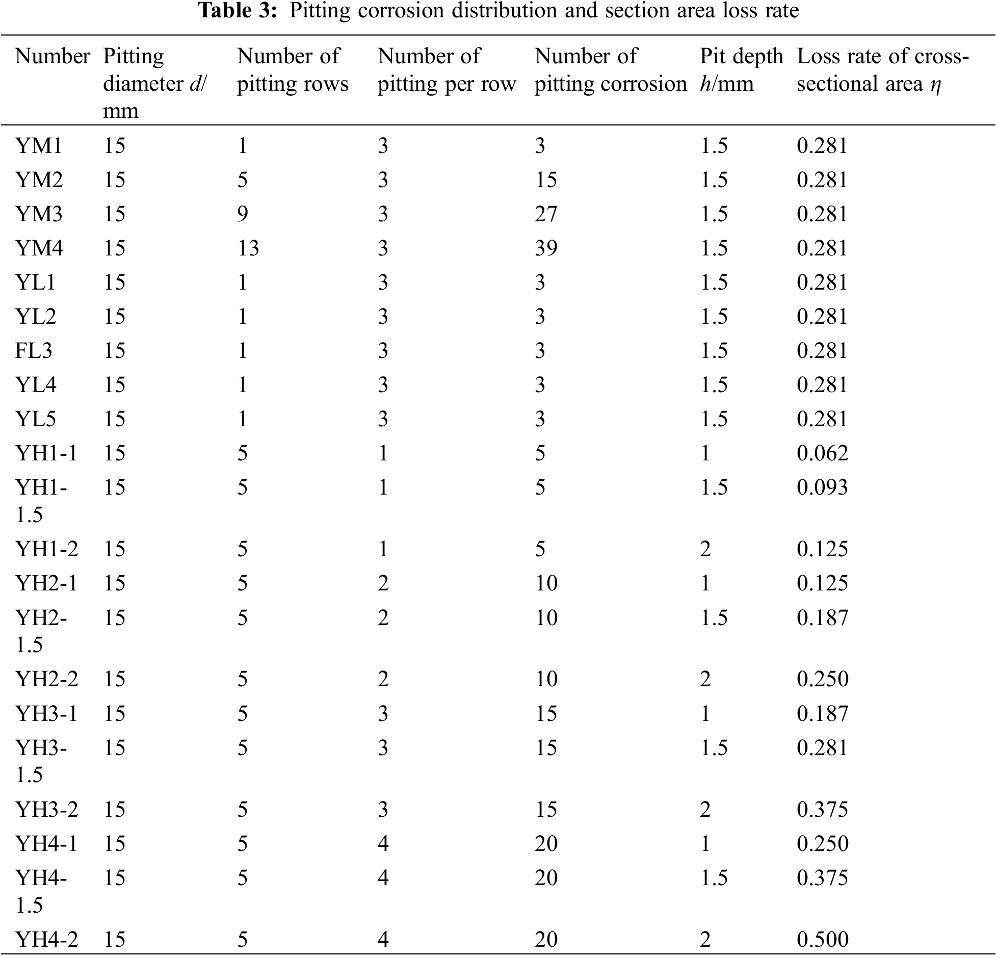
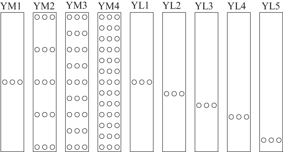
Figure 11: Distribution of flange pitting corrosion
4.1 Effect of Pitting Corrosion Area Ratio
Four cases of pitting corrosion area ratios are considered, which are 0.013, 0.066, 0.119, and 0.175, respectively. The distribution of pitting corrosion refers to Fig. 11, and the diameter and depth of pitting corrosion are 15 and 1.5 mm, respectively. The failure modes and load-displacement curves of different area ratios are shown in Figs. 12 and 13, respectively. It can be seen from Fig. 12 that the failure mode is changed into distortional buckling failure, and the reason is that pitting corrosion makes the flange weaker. When the flange is weak to a certain extent, distortional buckling is more likely to occur. The failure mode does not changed significantly with the increase of area ratio. When the pitting corrosion area ratio is 0.013, 0.066, 0.119, and 0.175, the ultimate load decreases by 10.92%, 10.06%, 12.43%, and 13.91%, respectively, indicating that the ultimate load decreases slightly with the increase of pitting corrosion area ratio. By comparing with the effect of area ratio, it can be found that the web pitting corrosion has a greater impact on the ultimate load.
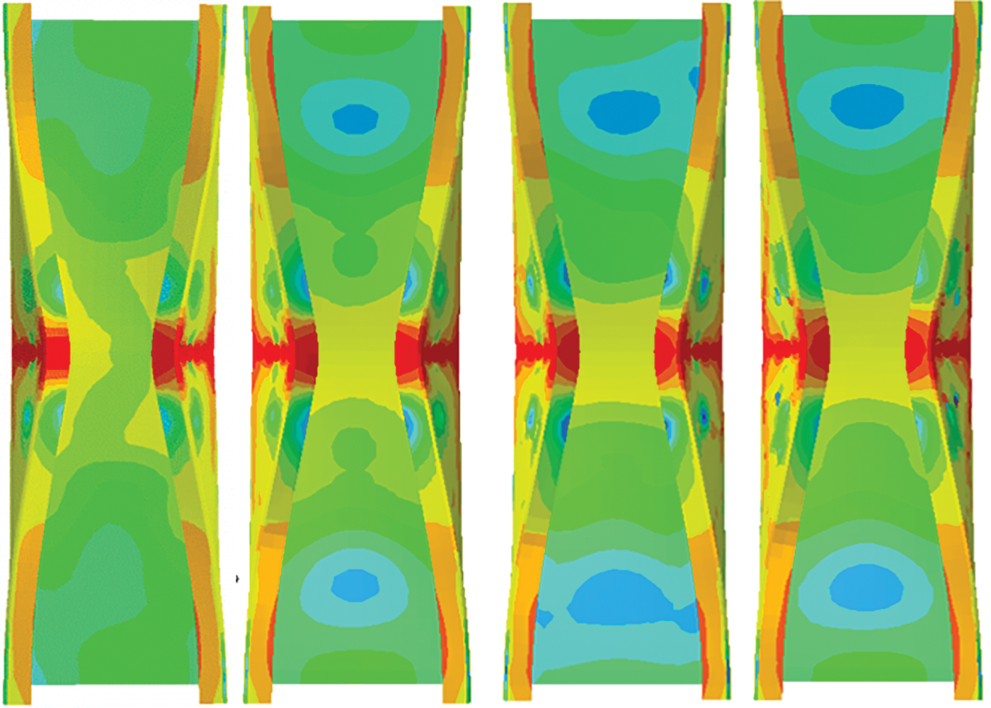
Figure 12: Failure mode of flange with different pitting corrosion area ratio
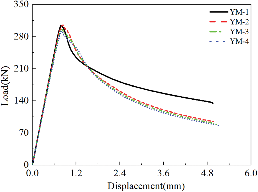
Figure 13: Load-displacement curve of flange with different pitting corrosion area ratio
4.2 Effect of Pitting Corrosion Location
Five cases of different pitting corrosion locations are considered. The distribution of pitting corrosion refers to Fig. 11. The diameter and depth of pitting corrosion are 15 and 1.5 mm, respectively. Figs. 14 and 15 show the failure modes and load-displacement curves at different pitting corrosion locations. It can be seen from Fig. 14 that when the pitting corrosion is in the middle, the specimen will undergo distortional buckling failure, and the pitting corrosion at other locations will undergo local buckling failure, which indicates that the flange is vulnerable to distortional buckling at the middle position. It can also be found that the failure of the test piece mainly occurs in the pitting corrosion section of the flange. As the pitting corrosion position is closer to the base, the deformation of the lower side of the pitting corrosion position becomes smaller and smaller. This is because the base constraint makes the part difficult to deform. The ultimate loads of test pieces YL1, YL2, YL3, YL4 and YL5 decrease by 10.92%, 10.79%, 10.62%, 9.83% and 8.34%, respectively. It can be found that the ultimate load does not change significantly with the position when it is close to the middle position. Although the failure mode has changed such as YL1 and YL2, the ultimate load has not changed significantly. As the pitting corrosion location is close to the base, the limit load increases continuously, which is due to the constraint of the base.
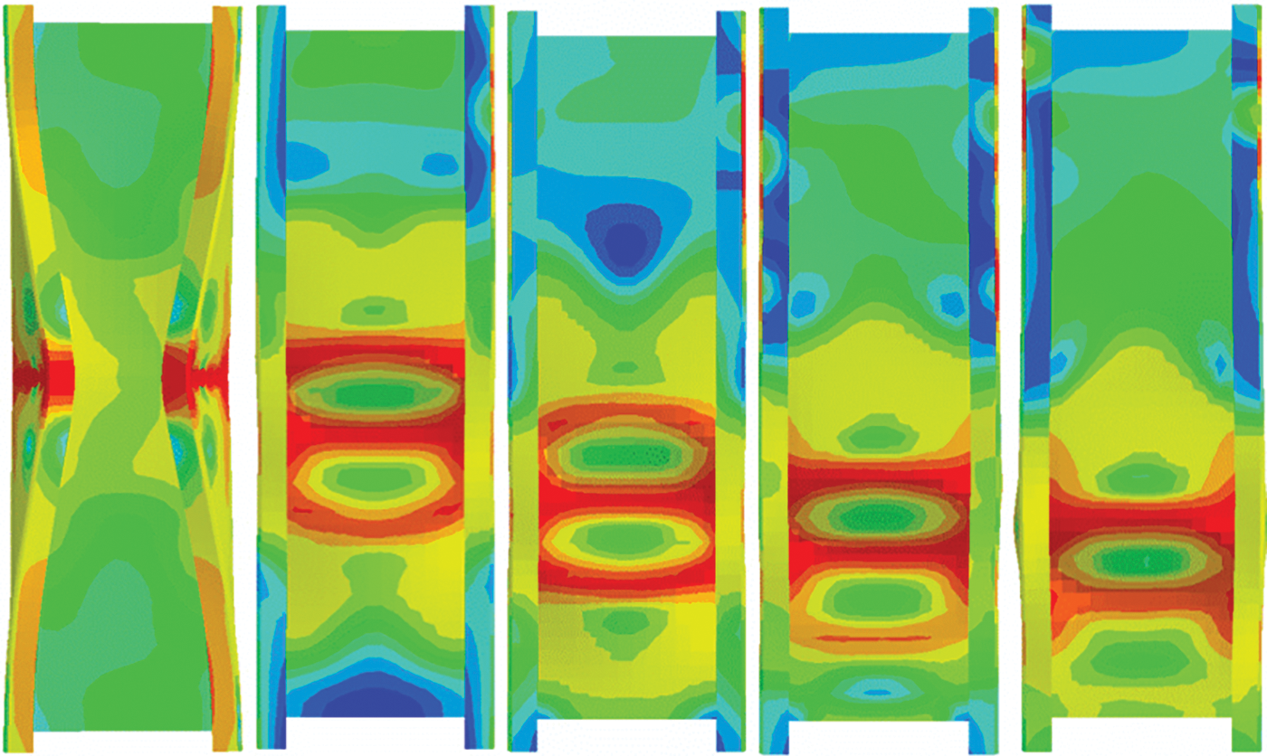
Figure 14: Failure modes at different pitting corrosion positions of flange
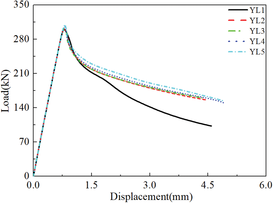
Figure 15: Load displacement curve at different pitting corrosion positions of flange
4.3 Influence of Flange Pitting Corrosion Depth
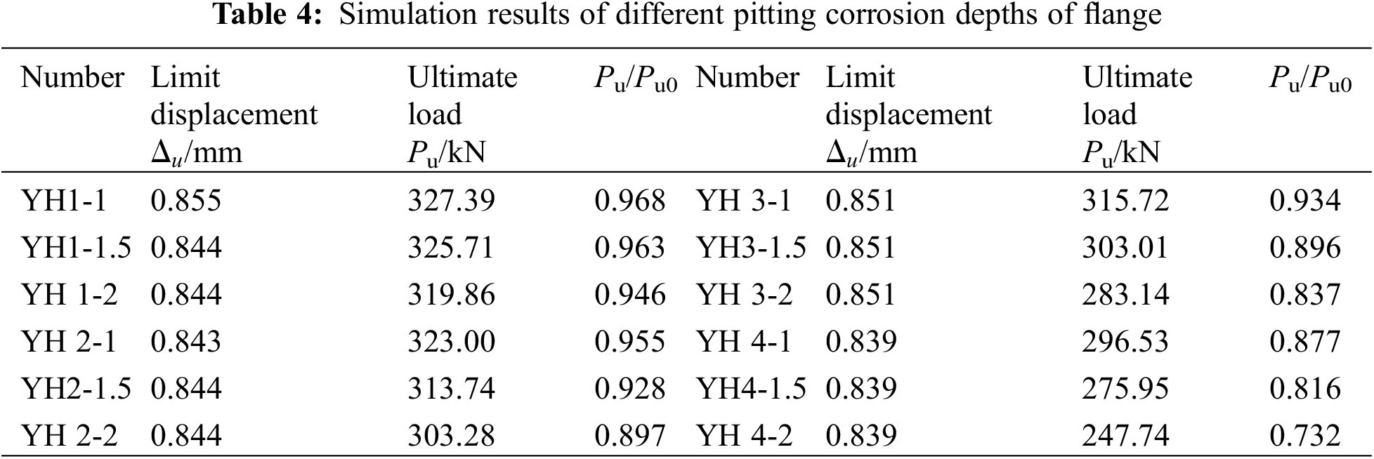
Three types of pitting corrosion depth are considered, which are 1, 1.5, and 2 mm, respectively. The distribution of pitting corrosion is similar to YM2, but 1, 2, 3, and 4 pits are arranged in each row, with a diameter of 15 mm. Fig. 16 and Table 4 show the load-displacement curves and simulation results of different pitting corrosion depths. The number of the test piece is YHi-j, where Y denotes the flange, H denotes the pitting corrosion depth, i is the number of pitting corrosion in each row, and j is a value of the pitting corrosion depth. It can be seen from Fig. 12 that with the increase of pitting corrosion depth, the stiffness of the rising section of the load-displacement curve decreases continuously, and the falling section becomes more gentle. This phenomenon is more obvious with the increase of the number of pitting corrosion in each row. The limit displacement does not change significantly with the increase of pitting corrosion depth and the number of pitting corrosion in each row, indicating that the pitting corrosion depth and the number of pitting corrosion in each row have little influence on the limit displacement. With the increase of pitting corrosion depth, the ultimate load decreased significantly.
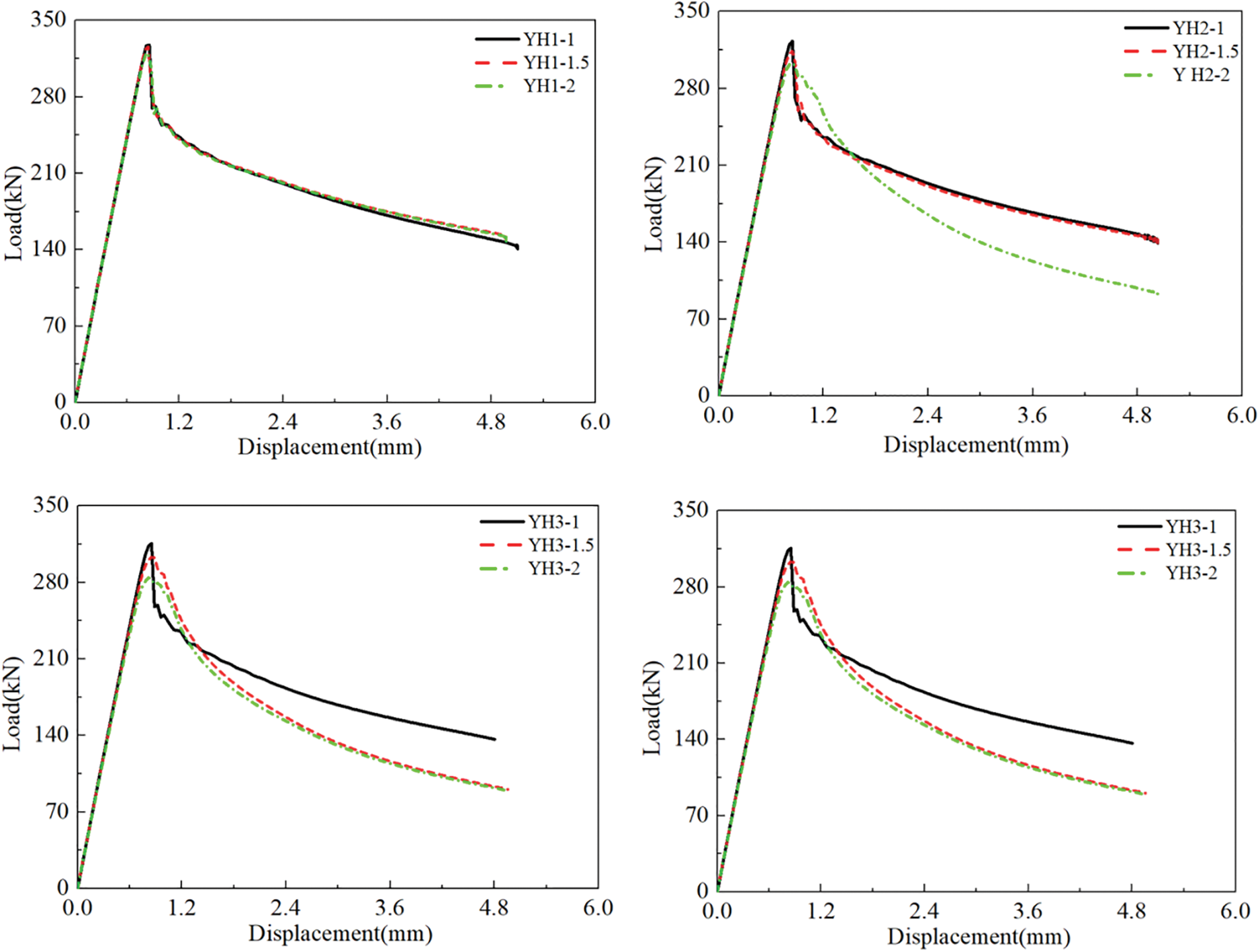
Figure 16: Load-displacement curve of flange with different pitting corrosion depths
4.4 Limit Load Prediction of Flange Pitting Corrosion
From the above analysis, it can be found that when the flange is pitted, the ratio of pitting corrosion area and the location of pitting corrosion have little influence on the ultimate bearing capacity, while the depth of pitting corrosion and the number of pitting corrosion on the same section have great influence on the ultimate bearing capacity. The failure mode may change with the change of pitting corrosion location and pitting corrosion area loss rate, but it mainly occurs in the pitting corrosion section. The minimum section area is also the main factor affecting the failure of cold-formed thin-walled section steel with flange pitting corrosion.
Fig. 17 shows the correlation between the loss rate of section area and the degradation coefficient, where the degradation coefficient is the ratio of the ultimate load of corroded specimens to non-corroded specimens. From Fig. 17, it can be found that the correlation is approximately expressed by a power function as follows:

Figure 17: Correlation between degradation coefficient and section area loss rate
According to the finite element simulation results, this study analyzes the influence of web and flange pitting corrosion on the mechanical properties of cold-formed thin-walled steel short columns, and the main conclusions are drawn as follows:
1. As for the specimens with pitting corrosion on the web, all the specimens are subject to local buckling failure, and the failure mode will not change with pitting corrosion, but the failure location will change with pitting corrosion location; the size, location and area ratio of pitting corrosion have little influence on the ultimate load of cold-formed thin-walled steel short columns, and the loss rate of pitting corrosion section area has a greater impact on the ultimate bearing capacity.
2. As for the specimen with flange pitting corrosion, the location and area ratio of pitting corrosion may change the failure mode, but the failure location mainly occurs in the pitting corrosion section; the location and area ratio of pitting corrosion have less influence on the ultimate load of cold-formed thin-walled steel short columns, and the section area loss rate has greater influence on the ultimate bearing capacity; the impact of web pitting corrosion on the ultimate load is greater than that of flange pitting corrosion under the same condition of pitting corrosion section area.
3. The prediction formulas of limit load which are suitable for pitting corrosion of web and flange are established, which can provide a reference for performance evaluation of corroded cold-formed thin-walled steel.
4. It is especially important to note that the bearing performance of cold-formed thin-walled steel columns is only suitable for short columns with pitting corrosion. And more experimental and numerical studies are needed to expand the scope of application.
Acknowledgement: None.
Funding Statement: This research is funded by the ‘Research Project of the Sucheng to Sihong Section of the Yanluo Expressway-Measurement Technology and Application of Bridge Quality Project Based on UAV Binocular Imaging (No. 00-00-JSFW-20230203-029)’, received by H. Z. Wang.
Author Contributions: The authors confirm contribution to the paper as follows: study conception and design: H. Z. Wang, S. J. Yang; data collection: C. H. Cheng, Z. H. Chen; analysis and interpretation of results: J. Chen; draft manuscript preparation: H. Z. Wang, J. Guo. All authors reviewed the results and approved the final version of the manuscript.
Availability of Data and Materials: The data used to support the findings of this study is available upon request by contacting with the corresponding author.
Conflicts of Interest: The authors declare that they have no conflicts of interest to report regarding the present study.
References
1. Fan, L., Nie, B. (2023). Surface characteristic of corroded cold-formed thin-walled steel in industrial environments. Anti-Corrosion Methods and Materials, 70, 284–293. [Google Scholar]
2. Li, Y., Wu, X. L., Gao, C. M. (2022). Compression performance and calculation method of thin-walled prefabricated steel tube lightweight concrete columns. Advances in Civil Engineering, 2022, 2011786. [Google Scholar]
3. Chen, B., Cao, L., Chen, Y. F. (2023). Experimental study on vibration serviceability of cold-formed thin-walled steel floor. Steel and Composite Structures, 46(4), 577–589. [Google Scholar]
4. Britvec, S. J., Chajes, A., Warren, K. W., Uribe, J., Winter, G. (1970). Effects of cold work in cold-formed steel structural members. Rolla Missouri: Center for Cold-Formed Steel Structures Library. [Google Scholar]
5. Wu, C., Duan, J. W., Yang, Z. H. (2023). Buckling modes of cold-formed thin-walled steel beams under different impact positions. International Journal of Steel Structures, 23(1), 236–246. [Google Scholar]
6. Jiang, X., Soares, C. G. (2012). Ultimate capacity of rectangular plates with partial depth pits under uniaxial loads. Marine Structures, 26(1), 27–41. [Google Scholar]
7. Jiang, X., Soares, C. G., Closed, A. (2012). Form formula to predict the ultimate capacity of pitted mild steel plate under biaxial compression. Thin-Walled Structures, 59, 27–34. [Google Scholar]
8. Wooszyk, K., Garbatov, Y. (2020). An enhanced method in predicting tensile behaviour of corroded thick steel plate specimens by using random field approach. Ocean Engineering, 213, 107803. [Google Scholar]
9. Qin, G. C., Xu, S. H., Yao, D. Q., Zhang, Z. X. (2016). Study on the degradation of mechanical properties of corroded steel plates based on surface topography. Journal of Constructional Steel Research, 125, 205–217. [Google Scholar]
10. Wooszyk, K., Garbatov, Y. (2020). Random field modelling of mechanical behaviour of corroded thin steel plate specimens. Engineering Structures, 212, 110544. [Google Scholar]
11. Ângelo, P. T., Guedes, S. C. (2008). Ultimate strength of plates with random fields of corrosion. Structure & Infrastructure Engineering, 4(5), 363–370. [Google Scholar]
12. Saad-Eldeen, S., Garbatov, Y., Soares, C. G. (2011). Experimental assessment of the ultimate strength of a box girder subjected to severe corrosion. Marine Structures, 24(4), 338–357. [Google Scholar]
13. Khedmati, M. R. (2015). Analytical simulation of nonlinear elastic-plastic average stress-average strain relationships for un-corroded/both-sides randomly corroded steel plates under uniaxial compression. Thin-Walled Structures, 86, 132–141. [Google Scholar]
14. Ok, D., Pu, Y., Incecik, A. (2007). Computation of ultimate strength of locally corroded unstiffened plates under uniaxial compression. Marine Structures, 20(1–2), 100–114. [Google Scholar]
15. Feng, L., He, J., Hu, L., Shi, H., Wang, S. et al. (2020). A parametric study on effects of pitting corrosion on steel plate’s ultimate strength. Applied Ocean Research, 9, 102026. [Google Scholar]
16. Paik, J. K. (2016). Ultimate compressive strength of deteriorated steel web plate with pitting and uniform corrosion wastage. Scientia Iranica, 23(2), 486–499. [Google Scholar]
17. Li, G. D., Zhang, W., Li, X., Yang, B. (2023). Flexural behavior of cold-formed thin-walled steel-glulam composite beams. Wood Material Science & Engineering, 18(1), 289–302. [Google Scholar]
18. Ahmmad, M. M., Sumi, Y. (2010). Strength and deformability of corroded steel plates under quasi-static tensile load. Journal of Marine Science & Technology, 15(1), 1–15. [Google Scholar]
19. Dunbar, T. E., Pegg, N., Taheri, F., Taheri, F. (2004). A computational investigation of the effects of localized corrosion on plates and stiffened panels. Marine Structures, 17(5), 385–402. [Google Scholar]
20. Yang, Y. A., Rh, A., Zheng, H. B. (2020). Experimental study of the uniaxial compressive behaviour of DH36 steel plates with mechanically induced pits. Ocean Engineering, 200(15), 107058. [Google Scholar]
21. Huang, Y., Zhang, Y., Liu, G., Zhang, Q. (2010). Ultimate strength assessment of hull structural plate with pitting corrosion damnification under biaxial compression. Ocean Engineering, 37(17–18), 1503–1512. [Google Scholar]
22. Zhang, Y., Huang, Y. (2017). Ultimate strength of ship structural plate with pitting corrosion damnification under uniaxial compression. Ocean Engineering, 130, 103–114. [Google Scholar]
23. Zhang, Y., Huang, Y., Zhang, Q., Liu, G. (2016). Ultimate strength of hull structural plate with pitting corrosion damnification under combined loading. Ocean Engineering, 116, 273–285. [Google Scholar]
24. Piscopo, V., Scamardella, A. (2018). Towards a unified formulation for the ultimate strength assessment of uncorroded and pitted platings under uniaxial compression. Ocean Engineering, 169, 70–86. [Google Scholar]
Cite This Article
 Copyright © 2024 The Author(s). Published by Tech Science Press.
This work is licensed under a Creative Commons Attribution 4.0 International License , which permits unrestricted use, distribution, and reproduction in any medium, provided the original work is properly cited.
 Downloads
 Citation Tools