
 Submit a Paper
 Propose a Special lssue
 Open Access
REVIEW

A Review of Infrared Thermography Applications for Civil Infrastructure
1 Department of Civil and Environmental Engineering, West Virginia University, Morgantown, WV 26506, USA
2 Department of Engineering Technology, Old Dominion University, Norfolk, VA 23529, USA
3 School of Sustainable Engineering and the Built Environment, Arizona State University, Tempe, AZ 85287, USA
* Corresponding Author: Onur Avci. Email:
Structural Durability & Health Monitoring 2025, 19(2), 193-231. https://doi.org/10.32604/sdhm.2024.049530
Received 10 January 2024; Accepted 28 November 2024; Issue published 15 January 2025
 View Full Text
 Download PDF
Abstract
Civil infrastructure is continuously subject to aging and deterioration due to multiple factors, which lead to a decline in performance and impact structural health. Accumulated damage on structures increases operational costs and poses significant risks to public safety. Effective maintenance, repair, and rehabilitation strategies are needed to ensure civil infrastructure’s overall safety and reliability. Non-Destructive Evaluation (NDE) methods are utilized to assess latent damage and provide decision-makers with real-time information for mitigating hazards. Within the last decade, there has been a significant increase in the research and development of innovative NDE techniques to improve data processing and promote efficient and accurate infrastructure assessment. This paper aims to review one of those methods, namely, Infrared Thermography (IRT), and its applications in civil infrastructure. A comprehensive review is presented by investigating numerous journal articles, research papers, and technical reports describing numerous IRT applications for bridges, buildings, and general civil structures made from different materials. The capability of IRT to identify and pinpoint anomalies, typically in the early stages of degradation, has excellent potential to improve the safety and shore up the dependability of civil infrastructures while reducing expenses tied to maintenance and rehabilitation. Furthermore, the non-invasive nature of IRT is beneficial in mitigating disturbances and downtime that may occur during various inspection procedures. It is highlighted that IRT is a highly versatile and effective tool for infrastructure condition assessment. With further advancement and fine-tuning of the available techniques, it is likely that IRT will continue to gain significant popularity in maintaining and monitoring civil infrastructure.Keywords
Buildings, bridges, roads, and water supply systems are crucial components of the general infrastructure system. They shape how modern society functions and provide essential building blocks for the foundation of a nation’s economic development. This fundamental role of civil infrastructure urged engineers and researchers to develop efficient and practical methods for maintaining structural integrity and functionality. For this purpose, it is always required to develop techniques capable of accurately assessing the condition of structures and the time rates of change, which would help in the decision-making process for maintenance, repair, and rehabilitation strategies.
Maintenance and repair are needed for civil infrastructure since the structures constantly face physical and chemical effects, furthering aging, and degradation. Such conditions occur due to human-induced and environmental factors. The natural deterioration of structural members is intrinsic, while human-induced effects could be machinery or disaster-related.
Infrastructure aging can cause a relatively slow but gradual decline in infrastructure performance and integrity, which can also pose a heavy risk to the safety of the public as well as the investment of stakeholders. Recent collapses of the Fern Hallow Bridge in Pittsburgh, PA, USA [1], and a multi-story apartment complex in Miami, FL, USA [2] highlight the fact that structural health cannot be underestimated. There is still a need to research and develop constructive maintenance, repair, and rehabilitation strategies to guarantee that infrastructures stay reliable and safe for the longest time possible. Generation and implementation of such a strategy need a well-versed understanding of the aging processes and internal mechanisms of civil infrastructures, along with an aptness to correctly assess their condition. Consequently, state agencies seek dependable, quick, commercial condition assessment techniques for infrastructures. Non-Destructive Evaluation (NDE) methods have been available and led the way in recent years.
Non-Destructive Testing (NDT) in civil infrastructure encompasses techniques and methods used to inspect various structural elements and components without needing to impede their performance or integrity. While in various publications, NDT and NDE are used synonymously, in some publications, NDT is restricted to the testing portion of the process. It can be stated that NDE includes both testing and the evaluation of the results. From this descriptive perspective, NDT is used to locate defects in a structure, and NDE is used to locate defects in addition to measuring the size, shape, orientation, and other physical characteristics of the defect.
NDT provides qualitative and quantitative data concerning in-situ properties and creates a continuous framework of material and mechanical properties and sub-surface anomalies for the structure, contrary to conventional visual techniques or coring methods. NDT is beneficial in many aspects, such as condition assessment, evaluation and rehabilitation of civil structures, and quality control for the beginning stages of construction work [3]. The various methods applicable for civil infrastructure assessments are categorized mainly as digital imaging, visual, electromagnetic, thermal, and acoustic methods. Namely, the NDT techniques include infrared thermography (IRT), Ground Penetrating Radar (GPR), Visual Inspection, Chain Drag, Electrical Resistivity, Ultrasonic Testing, Impact Echo, etc. [4,5]. Fig. 1 illustrates several methods and techniques used in the NDT of civil infrastructure to address critical issues, improve data processing, and promote NDT methods for more accurate infrastructure assessment.
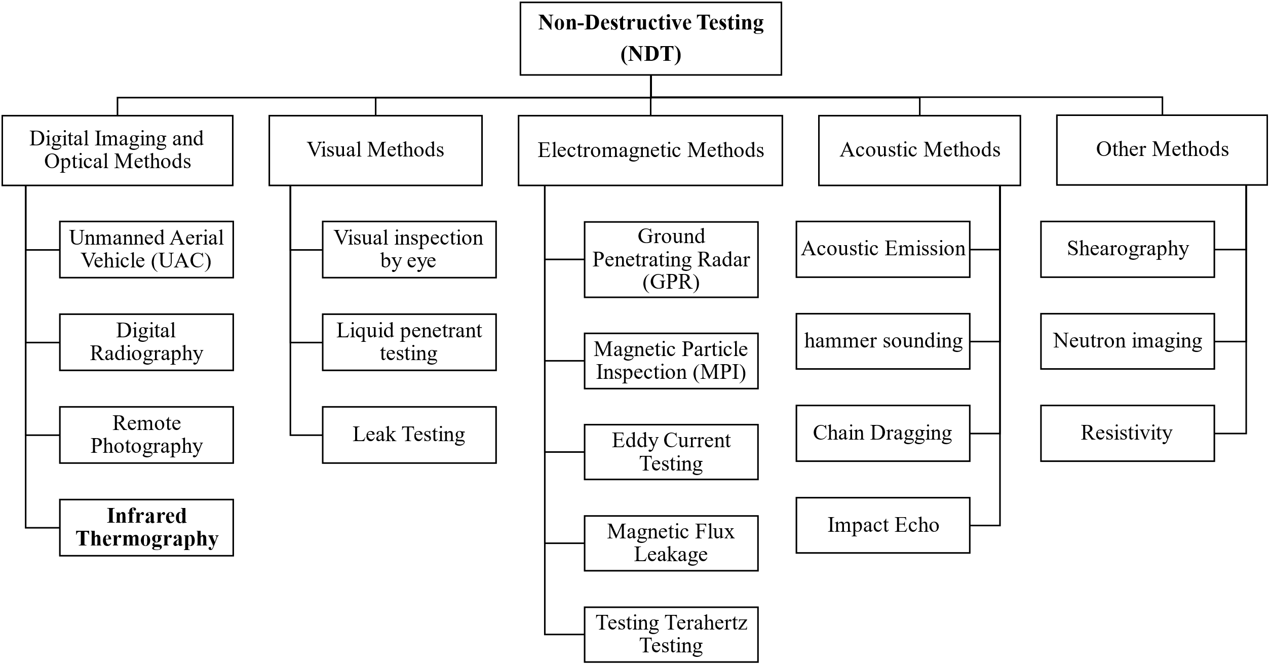
Figure 1: Classification of non-destructive testing (NDT) techniques
This review paper focuses on the use of infrared thermography, starting with its basic working principles, IRT applications for the inspection of bridges and buildings (with different construction materials) and concludes with IRT applications to unmanned aerial vehicle (UAV) technology. Including the most recent publications, the authors believe that the presented review is a comprehensive package of information on the topic. The methodology followed for the presented study is explained in detail in Section 1.2.
Authors are encouraged to use the Microsoft Word template when preparing the final version of their manuscripts. In introduction, authors should provide a context or background for the study (that is, the nature of the problem and its significance). State the specific purpose or research objective of, or hypothesis tested by, the study or observation. Cite only directly pertinent references, and do not include data or conclusions from the work being reported.
Infrared Thermography (IRT) employs an imaging system on the infrared scale to distinguish patterns and temperature recordings across a given area or surface. It is a fully non-contact and non-intrusive way of generating visible images from invisible heat energy emitted from any object. Thermal infrared radiation (IR) energy is emitted from all objects that have a temperature greater than 0 Kelvin (or absolute zero) [6]. IR represents the band of the electromagnetic spectrum that lies between the wavelength range of 0.74 and 1000 μm (Fig. 2) [7]. Most IRT applications in civil engineering use the wavelength range of 7–14 μm since this is the range where significant infrared emissions occur from bridges and buildings. The IR spectrum can be detected through specialized infrared cameras. The basic concept behind this is that the thermal imager inside the camera converts the invisible IR energy into a monochromatic or multicolored image representing the temperature range of the object. The resulting thermal image, called a “thermogram”, serves as the record for the temperature distribution across object surfaces. After appropriate post-processing of these thermograms and accurate interpretation, it is possible to gain critical data concerning regions where there is an unnatural non-conformity in the object’s material, determining their size and overall resistance to thermal energy [8] and allowing the observation of temperature changes in the structure. The total energy emitted by a radiating surface is defined by the Stefan-Boltzmann Law, which states that the net radiated power per unit area is proportional to the fourth power of an object’s temperature. This is represented by the equation below [7–9]:
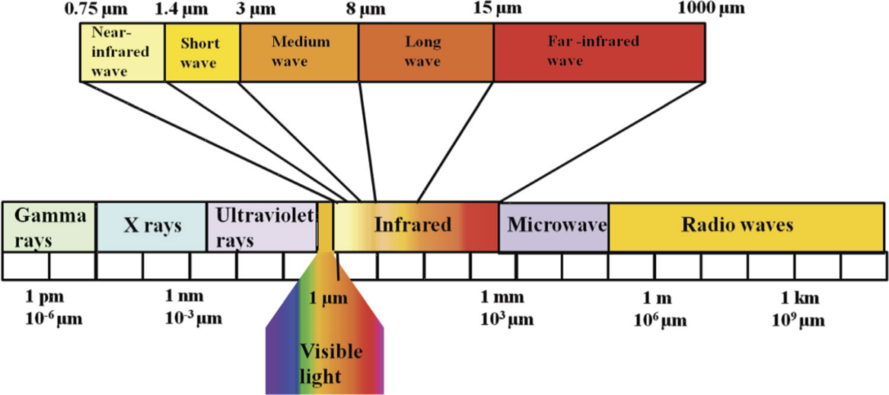
Figure 2: Electromagnetic spectrum. Reprinted from Reference [7]
where P represents the net radiated power per unit area (W/m2), ε is the emissivity, σ is the Stefan-Boltzmann constant (5.6703 × 10⁻⁸ W/m2K4), and T is the absolute temperature of the object (K).
The first infrared camera system was developed in 1929 for anti-aircraft defense [10–12]. Slowly, it was declassified and eventually made available to several other fields, such as human medical research, veterinary medicine, cultural heritage preservation, botany, aerospace, and mechanical engineering [11,13,14]. In civil engineering, IRT has been successfully employed and widely used in the condition assessment of various infrastructures, including bridges [6,15–17], buildings [18–20].
There are various ways to conduct IRT. Mainly, they are classified in terms of analysis scheme, mode, and measurement method. While examining defects of thermal properties on infrastructures, it is critical to use a suitable method based on the application of the IRT survey and the overall test conditions [21]. The primary classification of IRT is based on the energy source used to test target objects to generate the main surface temperature differential. Therefore, IRT applications can be classified as active or passive based on the energy source utilized. The breakdown of IRT with a focus on the active approach is shown in Fig. 3.
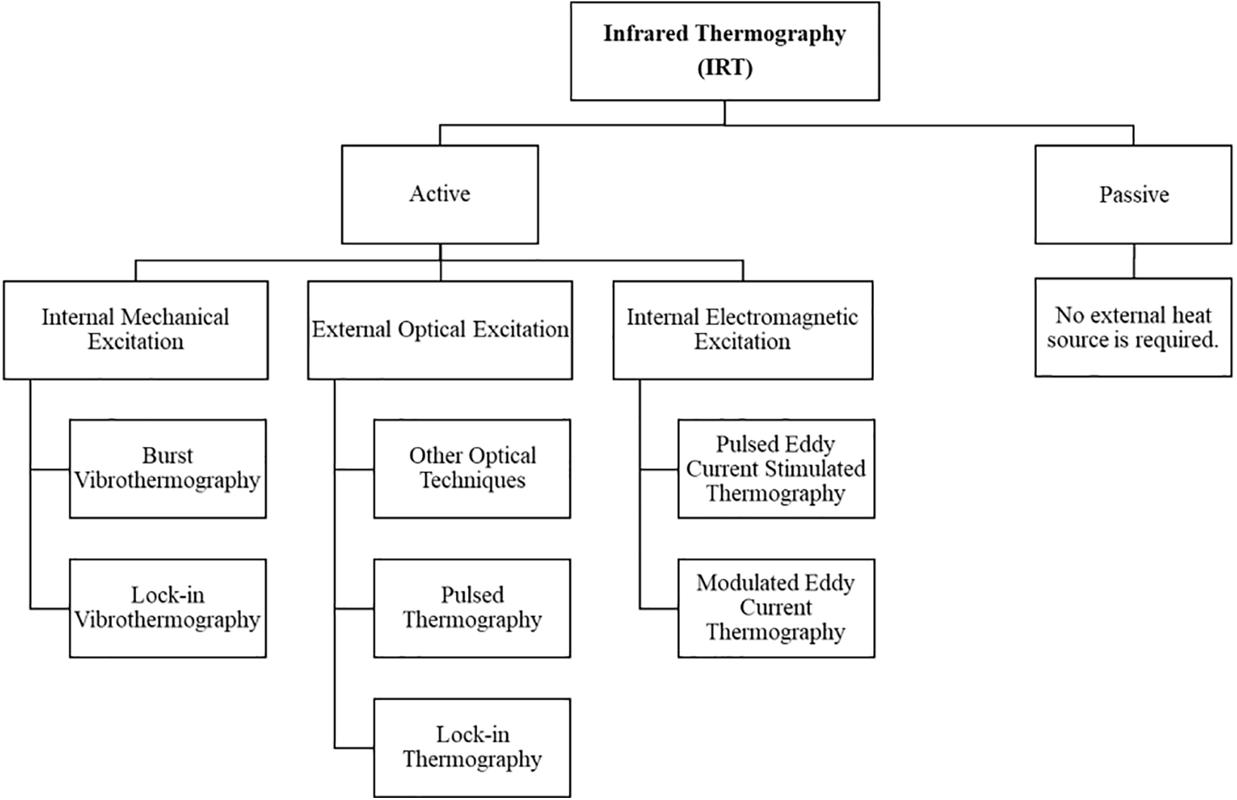
Figure 3: Approaches in infrared thermography (IRT)
Passive IRT prioritizes using natural heat sources such as the sun or solar heating as the main stimulus source to generate thermal differential inside structures or on the surface of test objects. This results in a significant thermal contrast on the structure’s surface between the sound and defective area [21]. Passive IRT is mainly employed during the testing of large zones, with the sun regarded as a sustainable and economical heat source and results in an even distribution of heating on the test object’s surface [22]. Some examples of passive IRT applications include moisture assessment, identification of insulation issues in buildings, condition evaluation of structures, construction site monitoring, structural health monitoring, etc. Passive IRT applications are somewhat limited for NDE compared to active IRT [7] due to a lack of penetration depth and an inability to provide quantitative results for sub-surface defects with large depths in test objects.
Active IRT is the form of IRT where an external heating source is utilized to create a thermal contrast in the test sample or structure [23]. External heating sources may include optical radiation, eddy currents or microwaves, and some form of mechanical ultrasonic waves [3]. After the application of heat excitation onto the test specimen, thermal contrasts are observed on the thermograms generated by internal defects [24]. Moreover, based on the mode or method of excitation for the heat source, active IRT can be further categorized as pulsed lock-in thermography (LIT), pulsed thermography (PT), vibrothermography (VT), step-heating thermography (SHT), long pulse thermography (LPT), phase thermography, among others [3,24,25]. During active IRT, signal levels associated with subsurface anomalies can get lost in the thermographic data noise. For this reason, various types of post-processing techniques are required to improve the signal-to-noise ratio (SNR) of the thermal output and overall thermographic data [26].
IRT offers a good number of advantages over other methods when it comes to NDE of structures and materials. First, it provides real-time visualization of test objects, allowing specimens with large surface areas to be inspected relatively quickly [4,27]. Second, it is an exceedingly safe, efficient, and relatively cost-effective method. For bridges, it can be used with minimum to no traffic disruptions. Third, direct contact between IR cameras and test subjects is typically not required, and IRT is non-invasive [26]. Obscured objects and structural elements can be easily viewed through IR cameras since thermal radiation can penetrate mist and smoke [5,16]. Lastly, infrared imagers are adequate for scanning and detecting structures under low-light surroundings, compared to conventional optical cameras [28]. All these make IRT particularly useful for construction monitoring and site engineering [29]. However, the efficacy of IRT surveys depends on several parameters. IRT tests, especially those done in the field, largely depend on environmental factors, which include solar radiation, wind speed, moisture content, emissivity factor of test surface, etc. [4]. The presence of external objects like trees, electrical lines, surface stains, dust, etc., also affects the results of IRT [16]. It is difficult to obtain information regarding defect depths from IRT compared to other NDE methods, such as GPR. IRT surveys also come with additional test equipment costs and need special training for the operators [27]. For composites, the anisotropy tends to produce completely different thermal properties in different directions, causing difficulty in composite inspections [30].
1.2 Methodology Used for the Presented Study
This paper aims to provide a brief overview of infrared thermography as an effective non-destructive evaluation method for the structural assessment of different types of civil infrastructure systems by reviewing related literature to highlight its versatility in the industry. For this paper, a total of 117 publications (journal articles, conference articles, and technical reports) related to the application of infrared thermography were reviewed. The applications include bridges and buildings with various construction materials such as reinforced concrete, steel, fiber-reinforced polymers (FRP), timber, and masonry. The method used to select these articles is listed below:
• The articles cited and reviewed in this paper were collected through indexes such as ASCE Library, Science Direct, Wiley, Springer, and similar online libraries using various keyword searches on Infrared Thermography.
• The keywords used to conduct the literature search were “infrared thermography for RC bridges”, “infrared thermography for steel and steel bridges”, “infrared thermography applications for masonry structures”, “infrared thermography for buildings”, “infrared thermography for historic structures”, “non-destructive evaluation for civil structures”, “timber defect detection using infrared thermography”, etc.
• Articles related to infrared thermography methods and applications for mechanical and aerospace structures were not included.
The collected papers were categorized based on the primary structure where infrared thermography was used or reviewed. The primary categories were bridges and buildings. The documents were grouped based on the construction materials used: Reinforced Concrete (RC), Steel, Timber, Masonry, and FRP. The reviewed documents cover a variety of defects, such as delaminations, voids, cracks, corrosion, dampness, debonding, etc., evaluated using active or passive IRT methods. Fig. 4 shows the work related to IRT in civil structures, mainly covering bridges or buildings. While the assessment of masonry and timber materials generally applies to buildings, steel, RC, and FRP elements are mostly surveyed for bridges.
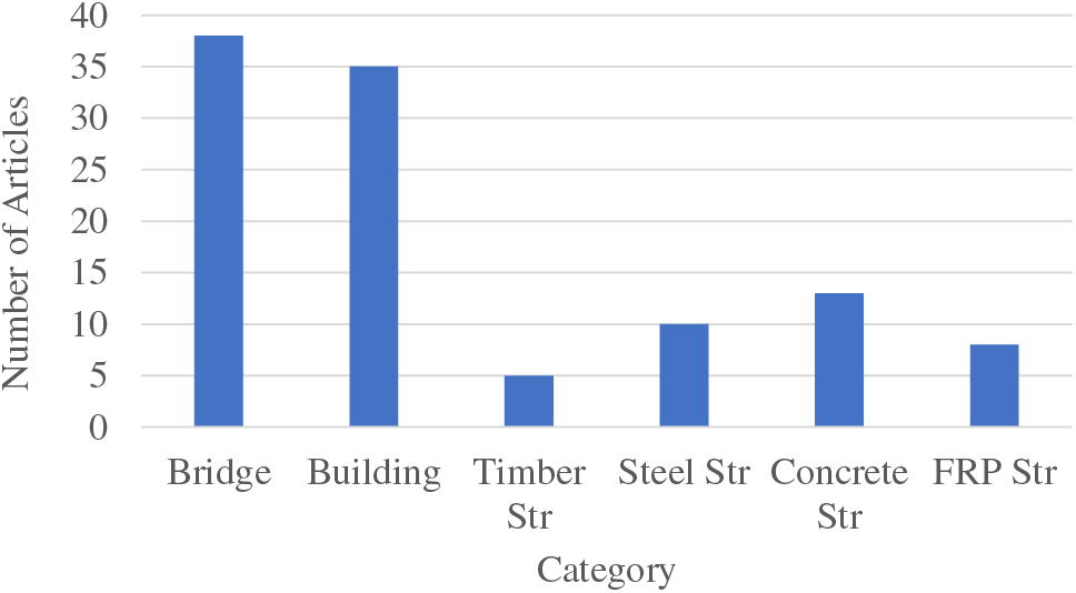
Figure 4: Distribution of the number of articles on infrared thermography applications in civil infrastructure, used in this study
2 Infrared Thermography on Bridge Structures
A bridge is a structure that spans over 20 feet and passes over a depression or obstruction, such as highways, roads, or water, generally to carry traffic. Bridges are integral parts of the civil infrastructure systems as they assist the transportation networks, providing leeway towards social and economic development. Hence, there is always a crucial need for bridges to be inspected frequently to keep them defect-free and functioning properly. Bridge inspection also provides structural inventory and appraisal data, which in turn establishes baseline structural conditions. As a result, engineers and inspectors can pinpoint minor defects and potential problem locations in bridge components before they develop into major issues in the future.
Although bridge inspection is crucial for maintaining the integrity and safety of bridges, Federal regulations in the form of the National Bridge Inspection Standards (NBIS) overlook the bridge inspection procedures across the various states in the USA [1]. Per the NBIS, most bridges are inspected at least once in two years, with underwater diving inspections conducted at least once in five years [31]. However, exceptions are allowed under certain circumstances [4] for larger (and longer) bridges with fractured critical members. The damaged bridges are expected to be inspected every year. With limited funding and approximately 42% of the 617,084 highway bridges in the USA being over 50 years old, state Department of Transportation (DOT) agencies have begun developing asset management plans to map out future bridge maintenance and expenses [32]. Steel bridges represent 33% of the total number of bridges in the USA [27]. During their inspection process, Bridge inspectors and engineers use various NDE methods, such as Visual Inspection, Impact Echo, Infrared Thermography, Ground Penetrating Radar, etc., to efficiently detect different types of deterioration and effectively plan out repair plans for the corresponding defects. This section of the paper discusses Infrared Thermography (IRT) application on bridge components made up of Reinforced Concrete (RC), steel, Fiber Reinforced Polymer (FRP), and timber materials.
2.1 Infrared Thermography Applications on Reinforced Concrete Bridges
The main idea of IRT for reinforced concrete bridge evaluation is that defects, delaminations, and subsurface voids intervene with the transfer of heat through and along the concrete. They also appear with different temperature signatures and thermal values on the thermal images relative to the area of sound concrete throughout the concrete [33]. Detecting the defective region in the surface temperature profile makes it possible to identify subsurface defects in concrete. When external sources of heat, such as the sun, heat up the surface of concrete or any test object, it emits radiation in the IR range of the electromagnetic spectrum, which is ultimately detected using a thermographic camera [34]. This allows the investigator to obtain thermographic images called thermograms, which are used to identify the mentioned abnormal regions on the concrete surface. A typical arrangement of a heat source and IRT camera to record thermograms for concrete surfaces is depicted in Fig. 5.
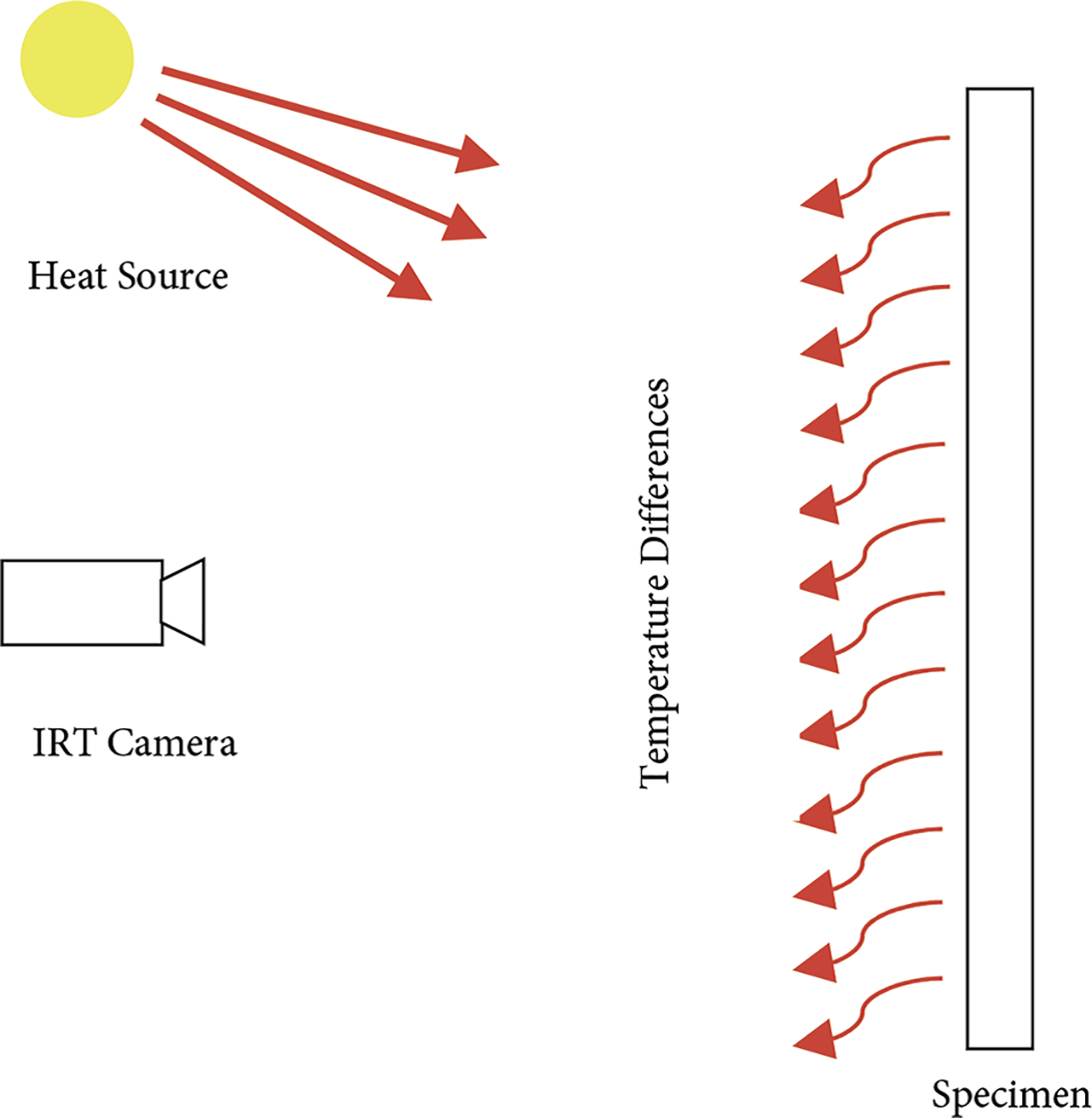
Figure 5: Typical equipment arrangement for bridge deck infrared thermography. Reprinted from Reference [34]
The variation of temperature between the defective regions and non-defective regions in concrete is related to the time of the day when measurements are taken. As the temperature increases during the day, radiant energy gets emitted out of the concrete, which initially absorbs the heat. Air voids and delaminations underneath the surface of the concrete will naturally try to resist the heat transfer and warm up concrete regions above them quicker than sound concrete surrounding them, making the delaminations appear as hot spots on the thermal IR image. On the contrary, during the night, when the ambient temperature decreases, the area of sound concrete around the air voids and delaminations ends up losing heat at a much lower rate compared to the delaminations [21,35] (Fig. 6). The delaminations appear as cold spots on the thermograms [33]. This mechanism is illustrated in Fig. 7.
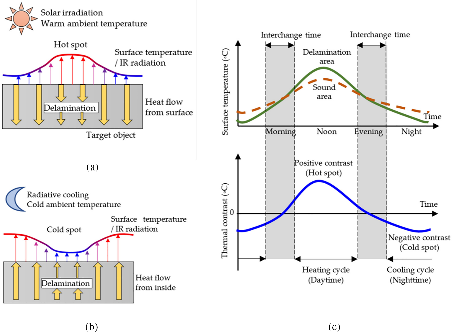
Figure 6: Heat flow during the (a) heating cycle daytime, (b) the cooling cycle nighttime; (c) daily changes of surface temperatures and thermal contrast. Reprinted from Reference [21]
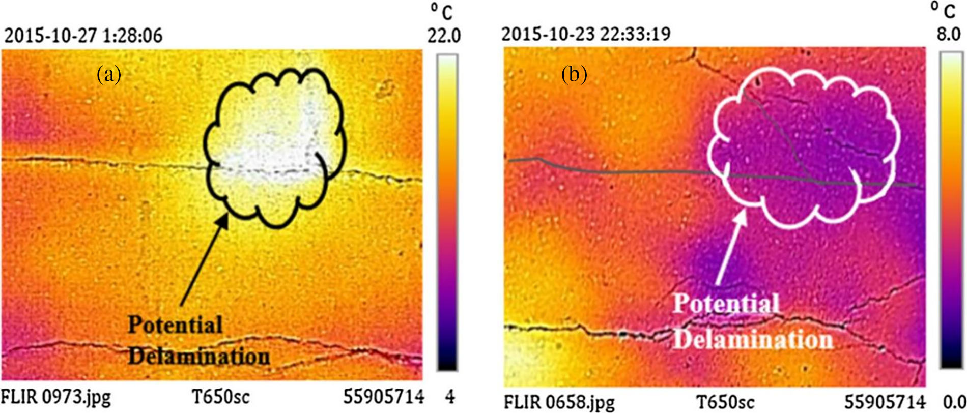
Figure 7: Examples of typical thermograms with potential delaminations, (a) daytime heating, and (b) nighttime cooling. Reprinted from Reference [9]
Different components of bridges are susceptible to deterioration, the bridge deck is a critical part that must be adequately inspected and well maintained. Not only does it carry the traffic, but it can be a cover for the rest of the substructure of the bridge. It is one of, if not the most susceptible components of the bridge that is highly prone to deterioration. This is because it is not only exposed to a significant amount of traffic load cycles but also to various chemical agents, such as deicing salts, which can ultimately lead to concrete degradation [36]. RC bridge decks deteriorate for many reasons, such as aging, deficiencies during construction, use of defective materials, exposure to weathering effects, and excessive traffic loading. Deteriorations appear in the form of cracks, steel reinforcement corrosion, delamination, and spalling (Fig. 8). Detecting these damages during the initial phases before spalling occurs is critical to ensure public safety, effective decision-making, and proper allocation of financial resources for maintenance, repair and rehabilitation goals of deteriorated bridges [6].
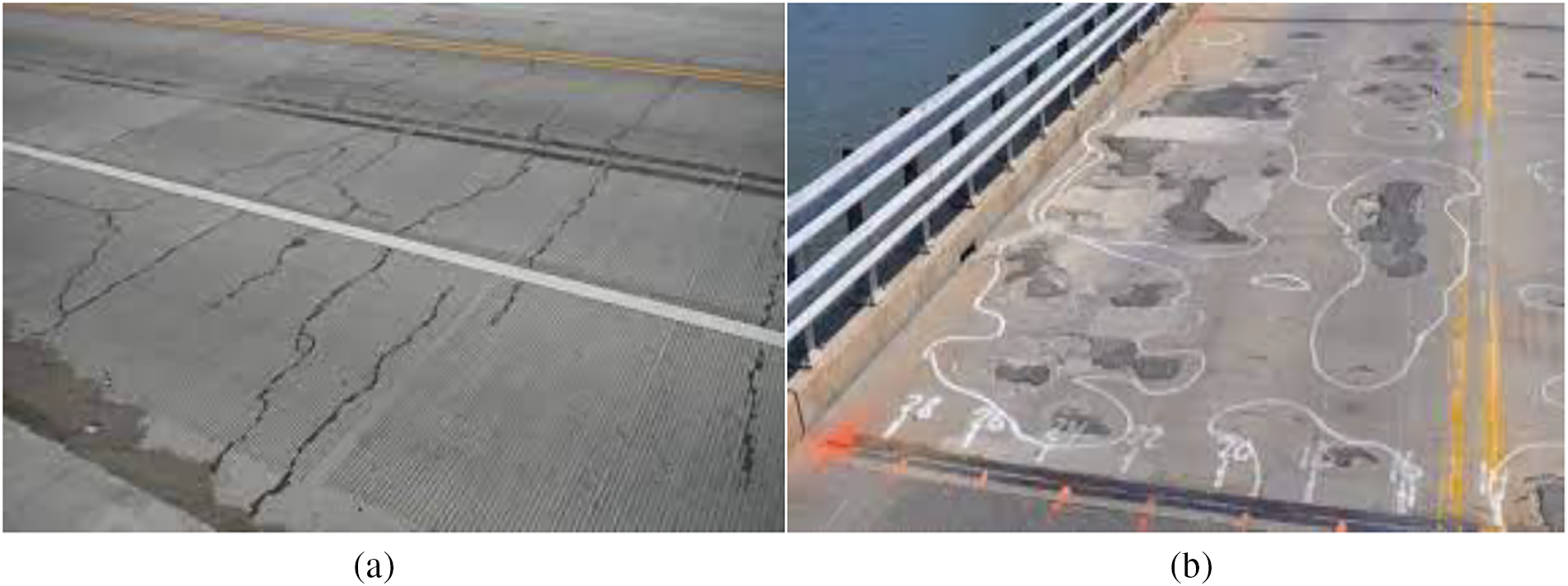
Figure 8: (a) RC deck with cracks, (b) spalling and potential delaminations. Reprinted from Reference [6]
Another defect that is common in RC bridges is steel rebar corrosion. Corrosion of the embedded rebars in RC elements is the leading cause of deterioration [4,37]. When steel rebar corrodes, its internal volume increases drastically, leading to stresses on the concrete, causing it to expand and resulting in cracks. The quality of rebar and the thickness of concrete cover are regarded as the primary protection against corrosion attacks in bridges [38]. Cracks can further lead to delaminations and spalling [39]. Such spalling exposes the underlying steel rebar to the environment, speeding up the deterioration process [6]. Furthermore, larger spalling can let potholes form on the surface of the concrete deck, which can cause damage to the vehicles driving over it and raise safety concerns for commuters.
The aforementioned defects that occur in RC bridges have to be well-assessed and treated. NDT methods such as chain drags and hammer sounding have been widely used to inspect concrete bridge elements and, in particular, the bridge decks. Visual inspection (VI) is considered to be the default inspection method, but its results heavily rely on the expertise and judgment of bridge inspectors and investigators, yielding primarily qualitative and subjective decisions [6]. Other NDT approaches allow early detection of the degradation processes and can be incorporated into the inspection process to assess the subsurface deck defects. For this, IRT can be considered a reliable technique since it enables quick surface inspection and qualitative data results in terms of IR images. However, its application also comes with a relatively high capital cost of equipment and greater reliance on favorable environmental and surface conditions [40].
Passive thermography is one of the IRT approaches that is used for bridge inspection. In passive thermography, the temperature distribution of the concrete surface and the heat source are the functions of the structural component and its surrounding environment. It is critical to decide when it is optimal to conduct passive IRT surveys on bridges. Pozzer et al. [41] state that spring and summer are the most appropriate times to conduct passive IRT surveys on concrete bridges. During active thermography, the operator provides a temperature gradient, and the following compensations are monitored and recorded over a fixed period [42]. Environmental factors such as solar loading, ambient temperature, and wind speed drastically affect the passive IRT test’s accuracy and plausibility [9].
On the concept of passive IRT, Coleman et al. [32] suggest a time between 12 p.m. to 1 p.m. to be optimal during daytime heating, stating that the time range has been shown to allow for significant temperature differential between sound and delaminated concrete. Watase et al. [17] argue that noon is the most favorable time to conduct IRT surveys for bridge decks due to the high-temperature differential found around that time. Moreover, for deck soffits, they recommend midnight to be the optimal time to use IRT for condition assessment. Mac et al. [39] report that passive IRT bridge surveys usually yield favorable results from 10 a.m. to 4 p.m. or 7:30 p.m. to 2 a.m. on a sunny day. ASTM D4788 describes optimal ambient conditions for quasi-passive IR data collection as usually 4–6 h after sunrise [42]. Washer et al. [43] report that the optimal time during the day to detect defects such as voids or delaminations is varied from a minimum of 5.5 h for specific 1″ deep voids to more than 9 h for 5″ deep voids (both after sunrise). Their study also concludes that there is a definite correlation between the overall depth of defects and the effective time to perform the IRT surveys. However, in another study conducted by Kee et al. [42], a modified methodology was used, which used the nightly cooling effects by taking periodic measurements. They concluded that overnight cooling of bridge deck specimens provided the best results for IRT to detect shallow and deep defects, generating clearer images than the morning heating effect. Each of the thermograms was taken 45 min after sunrise. They conducted this study in conjunction with the Impact Echo (IE) method and were able to detect shallow defects as well, but it was not as effective as IRT in detecting deeper defects. Janku et al. [38] conducted passive IRT bridge surveys in the Czech Republic and various lab experiments on concrete slab specimens. Their main goal was to detect the artificially embedded delaminations and determine the depth range. Their results showed that the shallower defects appeared much faster in the thermal images compared to those defects, which were relatively deeper with less contrast. This matches results obtained from active IRT tests done by Huh et al. [44] and Vaghefi et al. [33] on concrete slab specimens in a laboratory setting, where deeper defects reportedly took longer time to appear on the IR thermal images for a 20 min heating time compared to shallower defects. From their passive IRT test results, the authors urge using efficient thermal equipment and choosing days with optimal weather conditions and a suitable time during the day [15,16,45].
As for the active IRT approach, Huh et al. [46] studied the effect of depth, heating time, and capability of detecting delaminations using active IRT based on signal-to-noise ratio (SNR). SNR, as defined by the authors here, is the ratio or contrast between the regions of delaminated areas and that of sound areas. They report that shallower delaminations showed higher ranges of SNR value than those at a greater depth. They state that the SNR value decreases as the delamination depth increases. Also, higher values are directly proportional to the heating time of the external heating source used during active IRT. Finally, they conclusively determined that the SNR ranges above steel reinforcement in concrete were higher compared to those under the reinforcement. This means that it is challenging to detect defects under the rebars in concrete using thermal cameras.
The ASTM D4788 standard also recommends good testing conditions for bridge decks, such as continuous sunshine for at least 3 h, clean and unspoiled surfaces, and a dry bridge for at least 24 h before testing [40,42]. Coleman et al. [32] found that their IRT could not detect several defects on their bridge deck specimen because the surface was not dry enough before testing. Despite otherwise favorable conditions, they observed that water (rain, dew, etc.) on deck can inhibit long-lasting effects on its temperature profile. In their study, the authors also observed a large hotspot on their thermograms, which turned out to be a large surface stain (Fig. 9) that leaked from a simulated delamination composed of oil and sand. The authors suggest that since the surface of the deck was darkened by the oil stain, it caused a change in the localized emissivity of the surface, resulting in the subsequent hot spot.
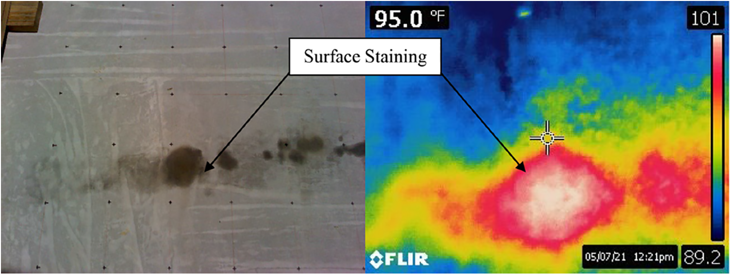
Figure 9: Hot spot caused due to oil stain on deck surface. Reprinted from Reference [32]
In addition to ensuring suitable testing conditions, the type of Infrared (IR) camera has to be carefully selected. Temperature, spatial resolution, and spectral range are some of the factors that must be considered when selecting an appropriate IR camera for the respective survey. IR cameras with much-improved resolution and accuracy have been developed by manufacturers due to a boom in the field of solid-state technology [9]. Long wavelength bands are recommended (7.5–14 μm) for cameras to detect small thermal contrasts while observing objects at ambient temperature. Furthermore, the spatial resolution of an IR camera depends primarily on the object-to-camera distance, its specific lens system, and the size of the detector [6].
An example of an IR camera is shown in Fig. 10. The shown camera is an advanced infrared thermal camera system, FLIR T650sc, utilized by Omar et al. [6] during their study on an in-service reinforced concrete bridge in Quebec, Canada. The IR camera has an uncooled microbolometer detector with a 5 MP built-in digital camera and displays thermal images with a 640 × 480 pixels resolution. For their IRT survey, the authors mounted the IR camera on a vehicle 8.5 ft from the ground surface facing straight-down towards the concrete deck surface. A 13.1 mm focal lens was used, which allowed a field of view (FOV) of 7 × 3.5 ft. to be achieved for each image and to survey each single lane of the bridge with only two predetermined paths. The IR cameras can be handheld, mounted on vehicles (as shown in Fig. 10) or carts, or even attached to drones to enhance even more contactless survey technology.
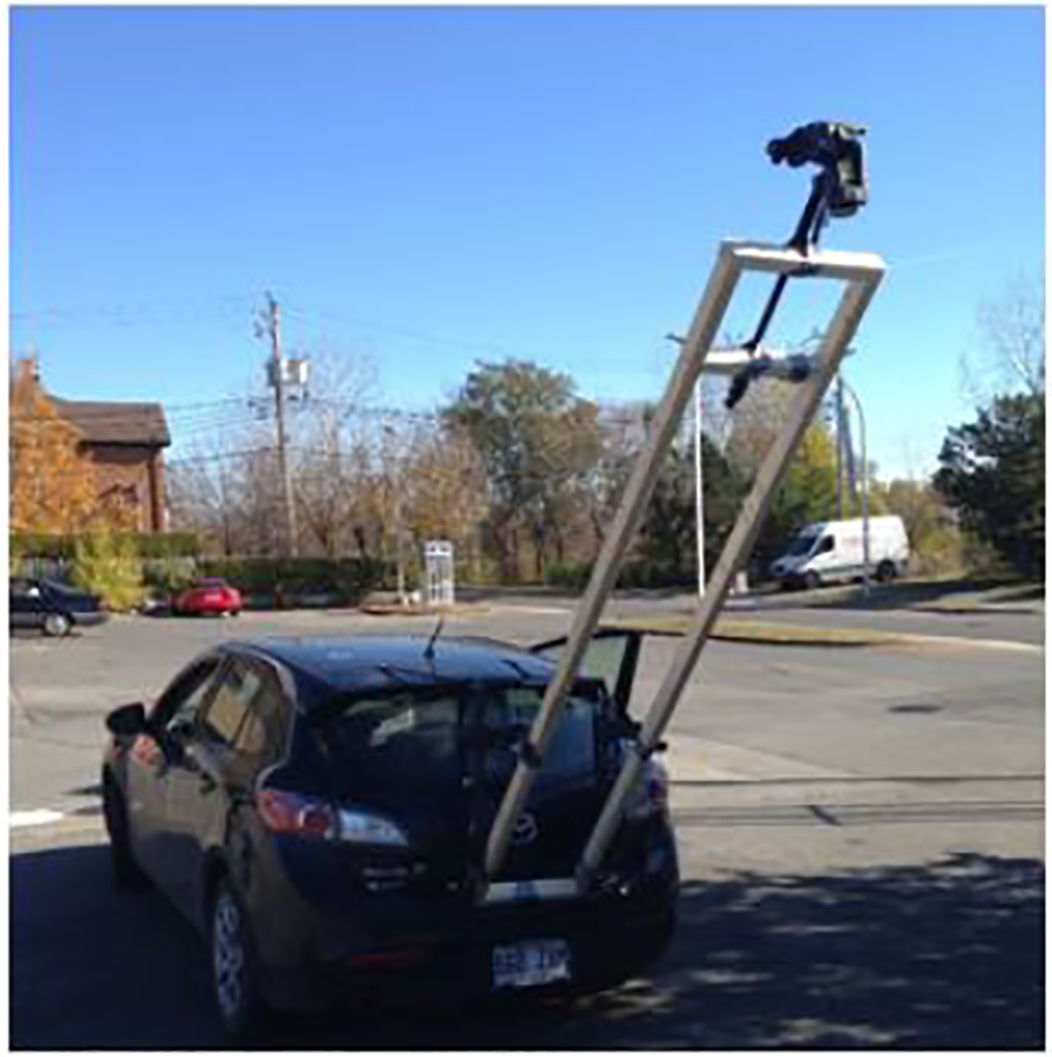
Figure 10: FLIR T650sc IR camera and vehicle-mounted setup. Reprinted from Reference [6]
After capturing all the images, the authors enhanced the IR images using software such as FLIR Tools+ and ResearchIR to improve the images’ quality. Pre-processing was also needed to conduct further analysis and to accurately identify the delaminated areas from the features of the deck surface like discoloration, oil stains, sand, and rust deposits that appear in the IR images, which are not relevant to the subsurface conditions. The authors also created a montage thermogram of the whole bridge deck from small individual images. A MATLAB code was written first to select a window from each image. Then selected windows were then extracted and stitched together in a successive order. Further codes were created to identify the temperature of each pixel and arrange them in a systematic order. Key specific thermal contrasts were then calculated from the temperature values of the mosaicked thermogram using a set threshold value of 1°C, which allowed the authors to highlight pixels with a higher temperature. Finally, all the temperature values were grouped into a condition map using commercial mapping software to construct a high-contrast image, which, as per the authors, accurately delineated the location of subsurface defects. The total percentage of the delaminated area was determined at the end by computing the total percentage of pixels with a higher temperature differential across the thermogram. The final image is shown in Fig. 11.
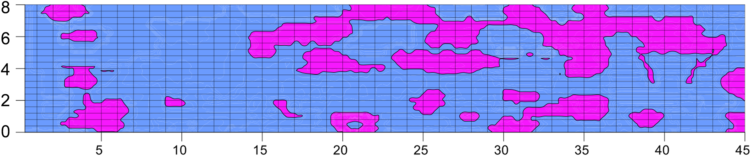
Figure 11: Map of surveyed bridge deck delaminated areas. Reprinted from Reference [6]
Omar et al. [9] further expanded on this work by validating the results they obtained from the IRT test with Ground Penetrating Radar (GPR) and Hammer Soundings as well. With GPR they found the condition maps from the two different tests to be comparable, with potential areas of delaminations and corrosion to have reasonable correlation. Furthermore, the IR delamination map the authors created matched well with the sizes and shapes of the defect found in the actual bridge deck through hammer soundings. Moreover, they conducted both daytime and nighttime IRT surveys, through which similar shapes and locations of the defects were found on the bridge decks. However, they report that the nighttime surveys failed to reveal all the defects that were present. The authors theorize that this may be attributed to the period of transition between the heating cycle to the cooling cycle when the nighttime IRT test was done, where there could have been an instant when the voids were not correctly detected by the IR cameras due to the lack of heat transfer phenomena.
IRT and GPR were also used by Maser [47], where an intensive passive IRT test and GPR test of 87 bridges was conducted during the summer of 2007 and 2008. The results obtained from both methods were combined. The tests were primarily conducted during the afternoon from 10 a.m. to 3 p.m. to maximize the temperature differential during the surveys. The results obtained from the IRT tests were ultimately validated using GPR. The author suggests using both methods together, stating that the combination of the two methods proved to be a robust methodology for RC bridge evaluation.
As for selecting the proper data collection method, Hiasa et al. [36] conducted a bridge deck experiment comparing three vehicle-mounted infrared cameras with different specifications. The vehicle was driven at different times with varying speeds, and results were obtained to investigate optimal data collection. The authors in the paper mention several factors that affect the utilization of IRT regarding detecting subsurface defects when it is used for bridge deck inspection at normal driving speeds. The specifications of the three cameras used, which were manufactured by FLIR systems, are shown in Table 1. The results of the test were plotted by the authors, as shown in Fig. 12.
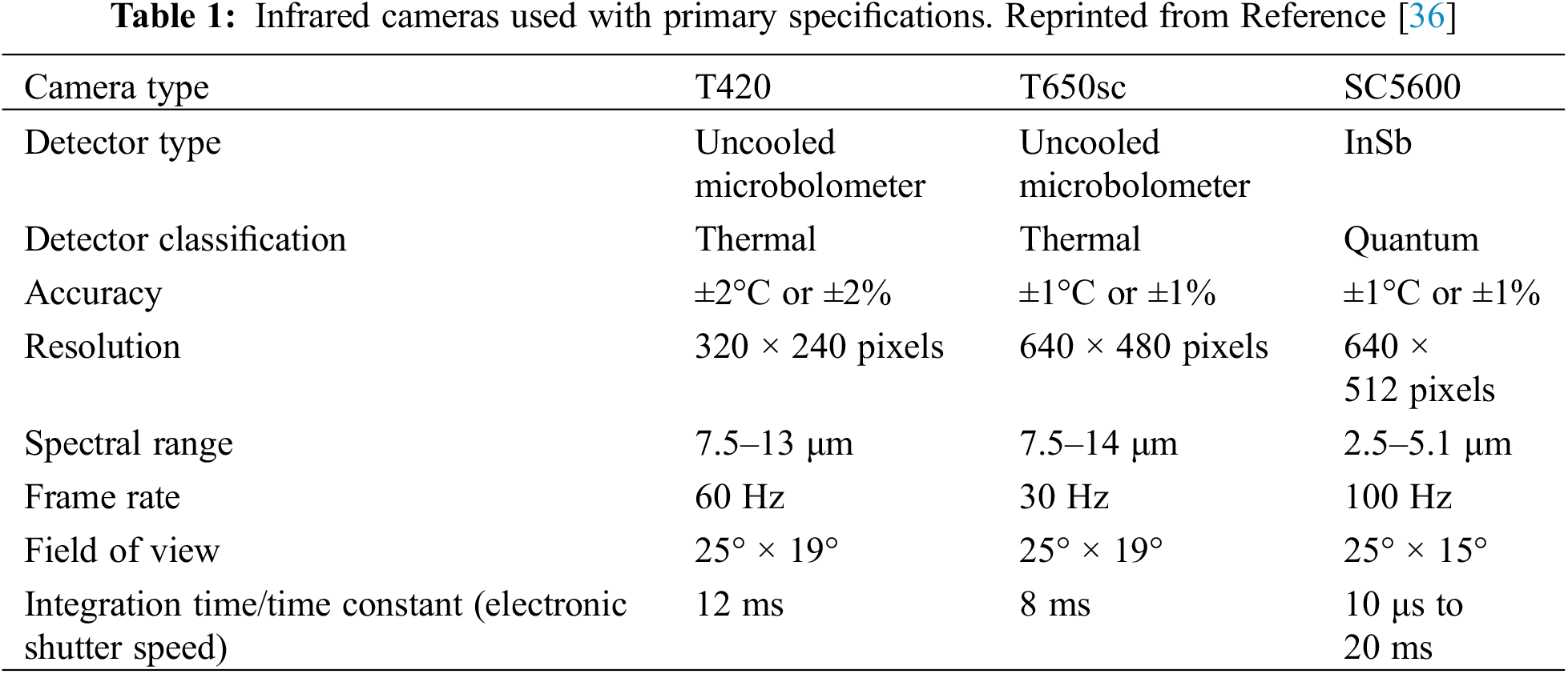
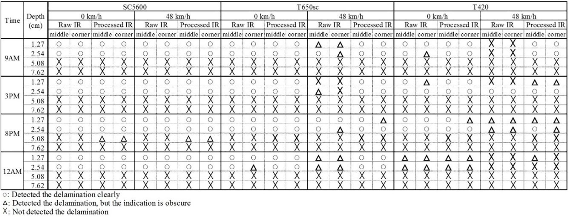
Figure 12: Sample results for delamination detection. Reprinted from Reference [36]
From the results above, it can be seen that none of the cameras were able to detect the delaminations that were embedded in the concrete slab specimen at 2″ and 3″ depth at any time. SC5600 performed the highest of all registered speeds. IR cameras with uncooled microbolometer detector type work based on converting the thermal energy it detects into electrical resistance. The temperature resolution for such cameras is generally in the range of 0.06 to 0.08 K. In contrast, IR cameras using indium antimonide (InSb) as detectors have high detection sensitivity. This is because it detects electrical energy based on light energy. Its temperature resolution lies in the range of 0.02–0.03 K and is comparatively faster [48]. As for T650sc and T420, the former performed better. The delaminations were unclear and larger at higher speeds taken by the T650sc and T420. The authors hypothesize that this may be due to the much slower integration time of uncooled cameras than that of cooled cameras [49]. This is somewhat certified by the fact that SC5600 did not show any differences between images taken at 0 and 30 mph at any time. It was also seen that even vibrations caused by the inactivity of cars at lower speeds (0 mph) affected the results of the IRT test with cameras, which have longer integration times. It was also found that the thermal images of IR camera T420 were much rougher than the images of other cameras, which made it difficult to identify the subsurface voids clearly. The roughness (heavy pixelation) was due to the T420 having four times lower resolution than the other two cameras. To mitigate this limitation, the authors obtained processed images from the Raw IR images. They found the processed images to be instrumental in detecting the previously difficult-to-detect delaminated areas. Especially for the uncooled cameras, the performance of the damage detection for high-speed inspection improved drastically, about 80% for T650sc and 150% for T420 (Fig. 13). As such, it was concluded by the authors that when IRT with uncooled cameras was utilized for high-speed inspection, the IR image was affected by the speed of data collection.
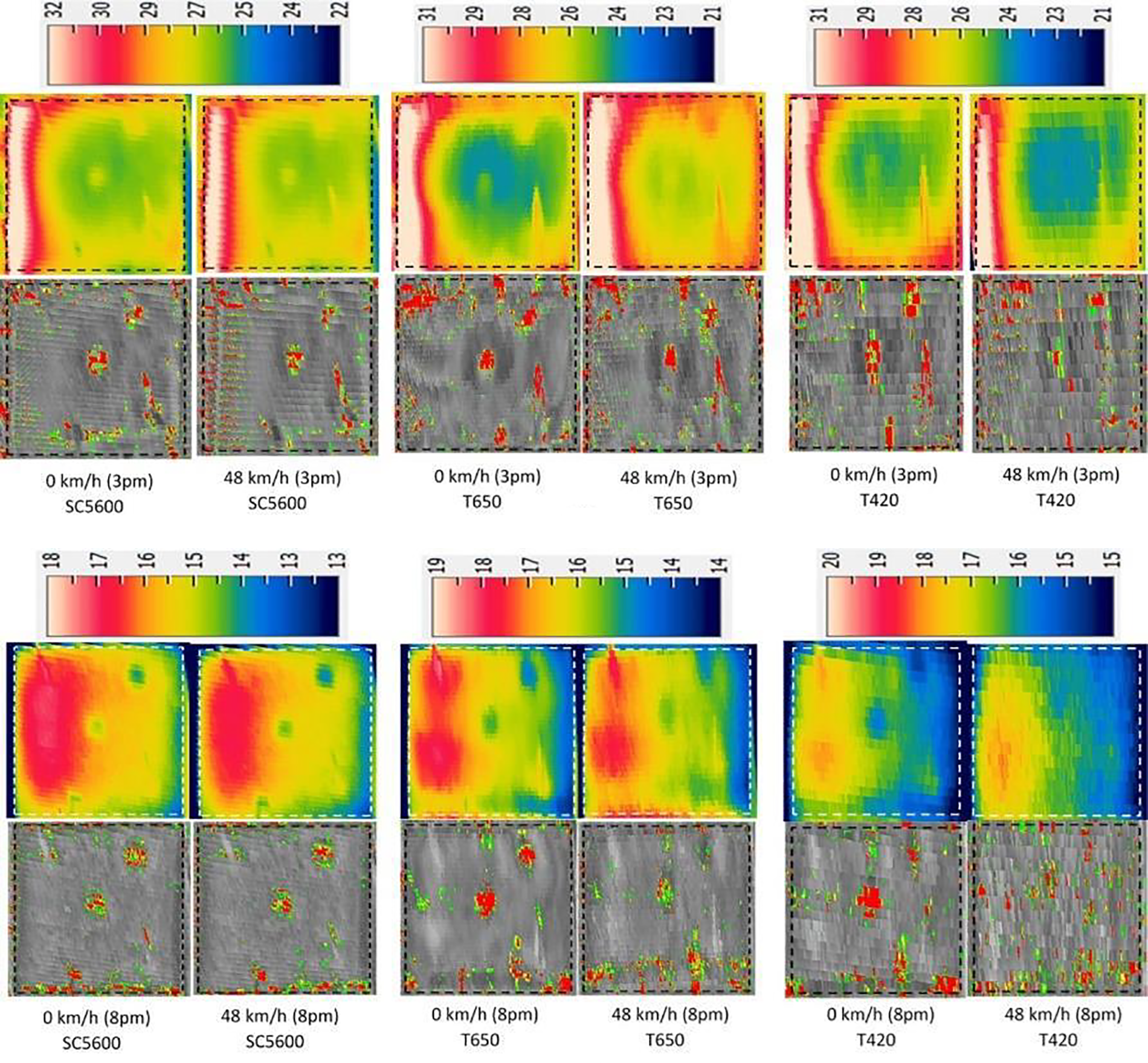
Figure 13: Comparison of 0.5″ depth images taken at 0 mph and 30 mph at 3 p.m. and 8 p.m. Reprinted from Reference [36]
Interpretation of the collected IR images has been the research focus for many scholars since highly pixelated thermal images usually make it difficult to assess them and yield plausible data properly. Moreover, visually interpreting the thermal results could lead to unsatisfactory results. Hiasa et al. [35] present a method that incorporates IRT data and Finite Element (FE) simulation to objectively obtain threshold temperature values for delaminated areas of a concrete slab specimen. Abdel-Qader et al. [50] created an algorithm that automates the inspection of thermal images without the need for human intervention. This algorithm aims to analyze and segment the thermograms into defected and sound regions so that regions of delaminations can be quickly identified, thus eliminating the mistakes that occur from subjective human data interpretation. They conducted their research on a concrete slab specimen in a laboratory setting using the active IRT method (Fig. 14), where the maximum depth of defect detected from the thermal images was 3″.
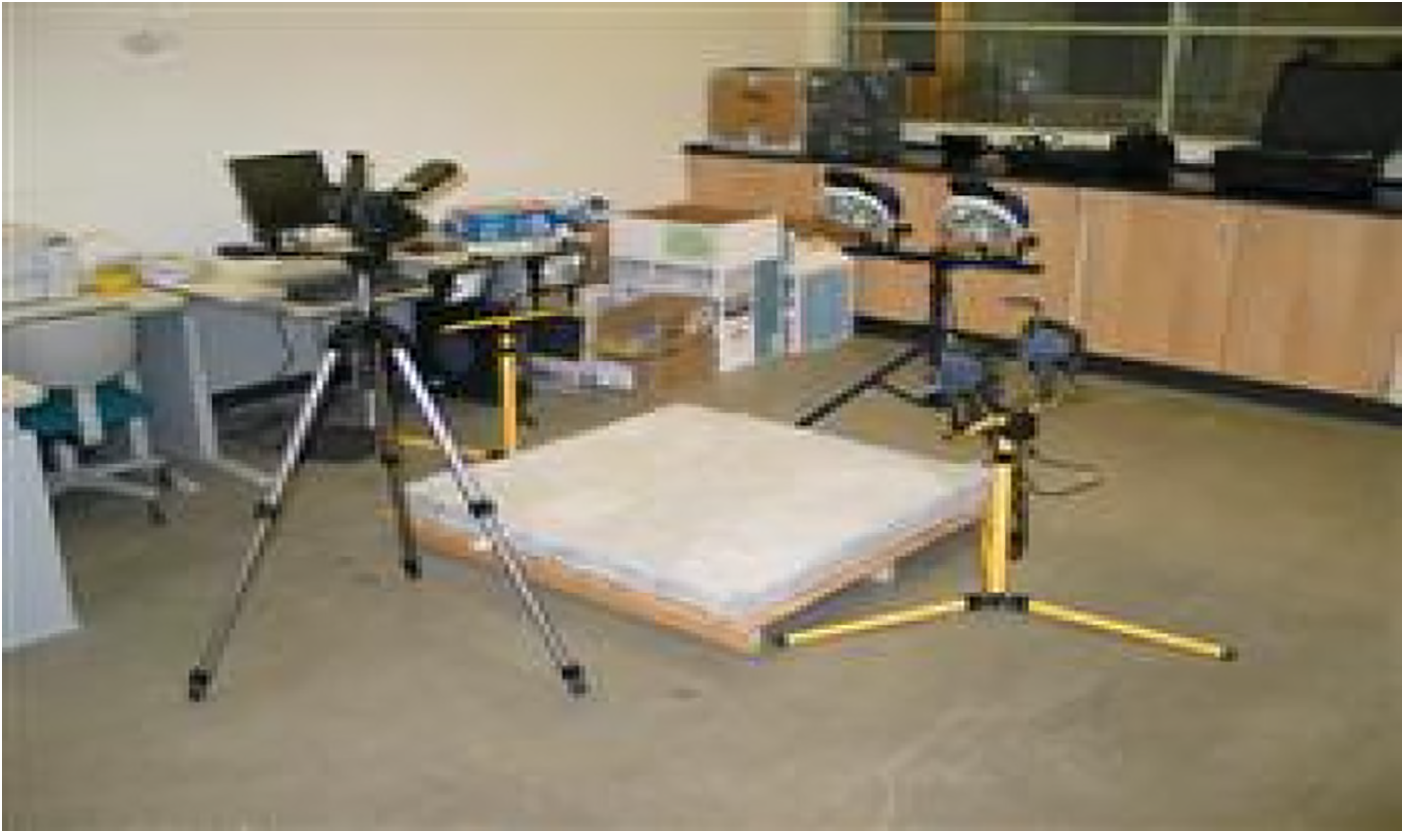
Figure 14: Active IRT experimental setup for defect detection in a concrete slab specimen. Reprinted from Reference [50]
While the application of IRT for concrete bridge inspections is observed to be practical, combined with other NDE methods to complement the results and validate the findings, IRT may be used successfully to gather accurate data and generate feasible condition reports. However, proper timing and environmental conditions for data collection must be predetermined to account for any potential errors that may jeopardize IRT results.
2.2 Infrared Thermography Applications on Steel Bridges
Steel is an excellent workable material that is used in many different civil infrastructure projects around the world. It provides superior strength, can provide significant workability for construction, and has a relatively good resistance to corrosion. It has a significant number of applications in civil engineering, ranging from buildings to bridges. However, one major challenge the material faces is the thinning of the walls, which may be attributed to a few reasons, predominantly accelerated corrosion and moisture. Other forms of damage that are expected in steel structures include delaminations, cracks, surface blemishes, wear, etc. (Figs. 15 and 16). Most of these sorts of damages are only detected visually at their advanced stages. Such modes of deterioration significantly affect the overall health and strength of the structure, which can lead to disastrous failures [23]. Therefore, there is a need for timely and proper structural assessment of steel structures and the material in general. Several NDE methods can be employed for this, among which IRT has proven to be an adequate method. Some of the ways it has been used in the field and laboratory are discussed in the section.
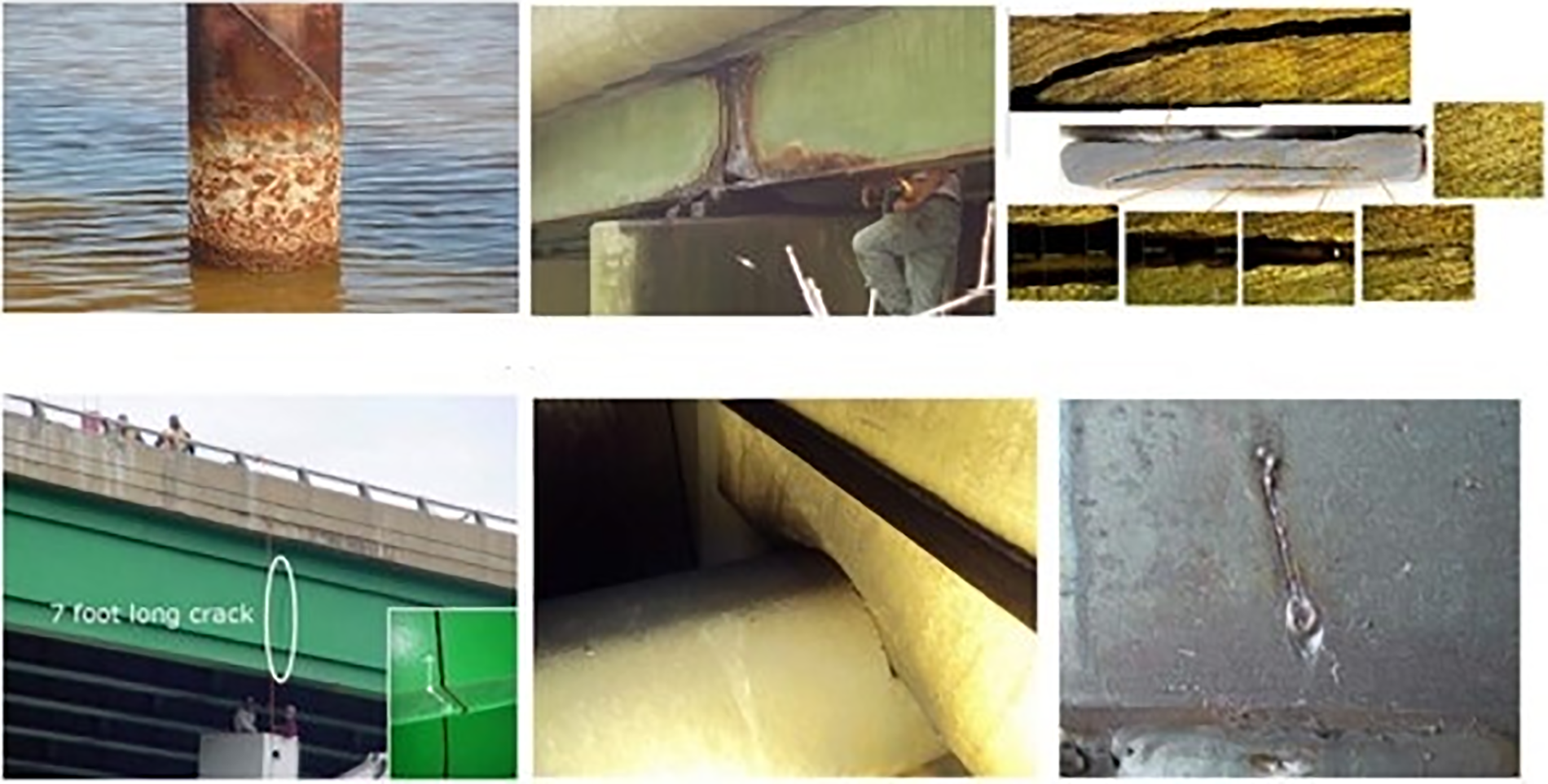
Figure 15: Common deficiencies in steel bridges. Reprinted from Reference [27]
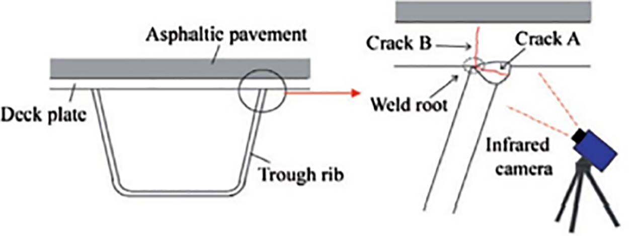
Figure 16: Schematic representation of fatigue cracks and IRT inspection. Reprinted from Reference [27]
Steel structures also experience fatigue which occurs after approximately 25–30 years of operation. Furthermore, fatigue damage starts to emerge on steel members of the superstructure of highway bridges, depending on the respective intensity of traffic. Fatigue damage usually occurs when there is a high accumulation of stress concentration and often at regions with a sharp change in the cross-section [51]. Fatigue slowly leads to cracking issues in the steel, which are tedious and difficult to detect visually. It is one of the more severe defects that is typically seen around the welds, which can ultimately lead to its failure [52].
In the literature, many studies focused on exploring different approaches for inspecting and detecting damage in steel structures. Chung et al. [23] used pulsed thermography (PT) to detect wall-thinning defects on a stainless-steel sample with flat-bottomed holes (FBH). To access the defects, various signal processing techniques and algorithms were used to evaluate the PT data and thermograms (with maximum deficiency to sound area ratio). Signal processing is deemed necessary to interpret thermal images correctly, especially if they are contaminated due to various “noise” sources like external reflections, optical variations, non-uniform heating of specimens, etc. [13]. The signal processing techniques used were Thermography Signal Reconstruction (TSR), Pulsed Phased Thermography (PPT) and Principal Component Thermography (PCT). The authors conclude that TSR, PPT and PCT were all able to detect the defects on the steel sample. PCT ended up being the most useful technique to detect larger and shallow defects. They report that PCT’s overall independence of results on several frames turned out to be a major advantage over other signal processing techniques. Ranjit et al. [53] explored the use of lock-in thermography (LIT) to accurately detect and estimate subsurface defects in stainless steel samples. Their results show that IRT in general, is a reliable NDT method to detect the size and depth of defects in steel. They further state that the accuracy of the method drastically improves as the ratio of defect size (or radius) to the depth of defect approaches unity. They claim that the efficacy of LIT depends on various factors such as material properties, dimension of defect, overall geometry, and surface finish of the steel element. The authors advise the use of better IR cameras in steel IRT surveys to garner more favorable results. Chulkov et al. [54] investigated various types of thermal simulation methods using active IRT when dealing with the detection of corrosion in steel samples around 1–2 mm thick. The authors concluded that halogen-powered lamps and air blowers yielded the best results when the signal-to-noise ratio was chosen as the comparison criteria. Furthermore, because of the steel sample’s inability to absorb emitted radiation, LED panels did not provide the expected results, and Xenon flash tubes were ineffective due to the thickness of the steel samples.
During IRT surveys for steel structures, an important phenomenon called the thermoelastic effect occurs. It is a noteworthy phenomenon because it plays a major role in the damage detection process, and it forms the basis for much of the stress distribution analysis. The thermoelastic effect is the phenomenon that occurs when there is a change in temperature during the elastic deformation of solid bodies. Deformations cause pressure regions or stress within the steel material itself, which can result in the generation or absorption of heat. Therefore, the stress-concentrated region can manifest as “hot spots” when IR readings are taken [55,56]. Sakagami et al. [57,58] performed extensive work on the application of the thermoelastic stress evaluation method to determine the severity of stress distribution reduction in members of steel bridges with fatigue cracks during repair and rehabilitation works (Fig. 17). They claim that it is possible to detect fatigue cracks by measuring stress distribution around the tips of cracks using the thermoelastic stress measurement technique.
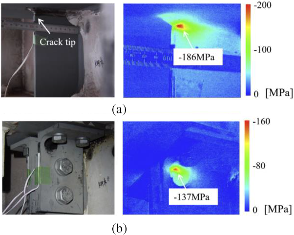
Figure 17: Thermoelastic stress distribution measurement results. (a) Before repair, (b) after repair. Reprinted from Reference [58]
Moreover, when discussing problems associated with the aging of steel bridges and other infrastructures, fatigue cracks propagating from welds around different parts of the steel members lie notably in the forefront. Conventional methods currently being used are not particularly useful to evaluate applied stress distribution or its history due to moving loads. Therefore, in their work, the authors recommend a stress measurement technique that enables remote measurement of stresses around fatigue cracks.
Induction thermography is another method within active IRT that is being used to detect subsurface defects and deterioration in steel members and specimens by researchers. In this method, electromagnetic pulses are employed to excite eddy currents in elements made from steel (and other electrically conductive materials), which generate heat because of resistive losses. The released heat is then detected by IR cameras. Moreover, cracks, subsurface damage, and hidden defects cause changes in the electrical current density of the material, which becomes visible in the thermal images [59]. IR camera operators need to be wary of the signal-to-noise ratio for induction heating IRT as well. For low heating power of induction source, the noise may become somewhat overpowering, which can jeopardize the results of thermal images and render unable to detect cracks [60]. A setup for induction thermography is shown in Fig. 18 used by Netzelmann et al. [59] for their study. EddyTherm current method can also be employed to detect cracks in steel components with promising results in laboratory settings, as reported by Zenzinger et al. [61].
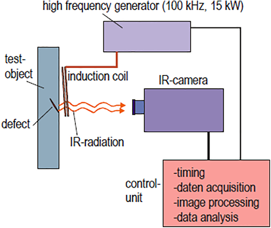
Figure 18: Schematic of setup for induction thermography. Reprinted from Reference [59]
As for rapid automated crack detection in steel bar specimens, Starman et al. [62] used PT (brief eddy currents) with a novel setup consisting of a circular coil through which steel bars are passed and heated. A total of 4 IR cameras were employed to track the release of heat and generate thermal images of the steel specimen. The system was also supplemented with signal processing algorithms and noise suppression methods, as reported in previous research, resulting in the detection of cracks and subsurface defects.
Hence, many IRT applications for steel bridges involve accurately assessing areas in steel components that may end up creating critical cracks, fatigue damage, and corrosion. Detecting regions of highly concentrated stress early on using IRT may contribute to the timely prevention of deterioration that may pose a severe risk in the future.
2.3 Infrared Thermography Applications on Fiber-Reinforced Polymer (FRP) Wrapped Bridge Components and Timber Elements
IRT is being recognized as one of the promising techniques and emerging methods when it comes to the investigation and monitoring of structural materials composition. It is one of the most frequently used NDT techniques in the field now, with a wide range of applications. Particularly in the sector of composites and Fiber Reinforced Polymers (FRP) as well. FRP materials are basically composite materials manufactured out of various fabrics such as Glass Fiber or Carbon Fiber and resins. FRPs are found to be common materials in civil infrastructures nowadays. Especially in the construction industry, they make up about 25% of the overall market share, followed by the automotive sector as of 2016 [63]. FRP composites are being used tremendously in the structural rehabilitation sector, especially to repair and maintain concrete and timber piles, pile caps, and old beams. FRP wrap applications to structural components such as columns, bridge piers, etc., can significantly enhance the overall structural strength and ductility of the components [64]. FRP materials tend to have a high strength-to-stiffness ratio. Also, they provide excellent fatigue resistance and low deterioration levels compared to steel, concrete, or timber [65]. Therefore, the use of FRP components for rehabilitation has gained popularity. However, large debonds between FRP wraps and the underlying components, such as columns and beams, considerably reduce the ductility and compressive strength.
In a laboratory experiment, IRT was applied to detect anomalies in GFRP and CFRP-wrapped cylindrical concrete samples [64]. In the thermograms of the tested specimens, the air-filled debonds appeared as bright spots, where a total time of 70 s was enough to provide a great contrast between the defect and sound areas. The loss of such bonds in FRP usually means a reduction of confinement, which can lead to loss of load-carrying capacity for structures like columns [65]. Detection of such air-filled debonds is generally possible if there is a clear separation (gap) between the FRP wrap and the underlying material surface. Debonds with little to no gaps may not be easy to detect using IRT [65]. Shardakov et al. [66] successfully tested RC beams wrapped with CFRP composites. They performed a basic 4-point bending test on the beam specimen in the laboratory where the specimen was externally heated, and active IRT was performed to detect initial debonding between the FRP layer and underlying concrete. Foudazi et al. [67] used a novel method combining active IRT and microwave NDT called ‘active microwave thermography’ to inspect a mortar sample consisting of a surface-bonded CFRP with a delaminated section. Delaminations were visible on the thermograms under a microwave illumination of 50 W at 2.4 GHz.
The results of IRT to detect defects in FRP materials vary when it comes to the detection of air-filled voids and water-filled voids. This is due to the thermal conductivity and specific heat properties of air and water. Water has much higher thermal conductivity and specific heat relative to air. Hence, air-filled debonds provide a much more contrasting thermal differential profile in the thermograms after IRT surveys. Furthermore, in FRP materials, the thermal conductivity properties across the material’s thickness are determined more by the resin used and less by the fibers [68].
In general, water-filled debonds are expected to appear as cold spots in thermograms due to the thermal conductivity properties of FRP materials [68]. This results in IRT being less effective in detecting water-filled debonds. GPR, on the other hand, is much more effective in detecting water-filled defects because the dielectric constant value of water is very high, which results in higher ranges of amplitude reflections in and around the FRP fabric and water surface. However, Halabe et al. [68] successfully identified air and water-filled debonds of all sizes using active infrared thermography in a laboratory setting of polymer-wrapped composite samples. In the experiment conducted, the water-filled defects appeared as hot spots in the thermal pictures. This was attributed to the thin layer of the wrap being used in the composite samples. This, coupled with the very high specific heat value of water, resulted in the water storing a strong amount of heat energy, which was ultimately released during the cooling cycle when the thermograms were taken.
IRT has a lot to offer in terms of detection of anomalies and hidden objects. One of the major differences between GPR and IRT is that the former is very capable of detecting water-filled defects in concrete and FRP structures. Research conducted by Hing et al. [69] concluded that IRT is a comparable method when it comes to the detection of water-filled defects, given a large enough heating mechanism. They recommend using IRT and GPR in conjunction so that the detection of defects (both air and water) becomes effective on bridge decks. Using other NDE methods, such as Digital Tap Test, also provides a quick check on the IRT results since the results of the two techniques generally complement each other [70].
Through novel research that was conducted, Kavi et al. [71] proposed applications of IRT to detect buried pipelines in soils. Hot materials (gas and liquids) flowing through the length of the pipeline create a good differential in thermal patterns between the surrounding soils and underlying pipes, which can be effectively detected using thermal cameras. Even though there are some restrictions when it comes to soil depth, this application of IRT can be deemed very promising. Similar uses can be explored to detect various hidden elements in bridges and buildings, which may contribute to effective structural health analysis and rehabilitation.
Infrared Thermography has also been labeled to be a perfect method to detect various defects in wood structures [72]. When it comes to the inspection of timber bridges, various properties of the timber are evaluated, such as its strength, porosity, anisotropy, impact resistance, durability, and fire resistance. Typically, visual inspections are conducted, but they come with a few limitations. These include the lack of accuracy in inspecting and detecting decay and the difficulty in inspecting structural members visually if they are covered by asphalt or concrete or if they are underwater [73]. This is where NDE techniques such as IRT come into the picture.
In buildings where the main roof framing structure is built from timber, moisture-related leakage from the roof is a serious issue. Usually, for timber elements, the absorption of moisture is quick compared to the desorption [74].
The thermograms of timber surfaces are typically affected by various factors. These include the thermal characteristics of the timber specimen, age, microclimatic conditions, emissivity factor, and the state of deterioration [72,75] (Fig. 19). In fact, Crisóstomo et al. [76] state that the right way to determine the correct temperature values for IR thermal systems is to correctly establish the emissivity value of the wood material that is to be tested. They maintain that proactively doing so will help avoid unfavorable results from the subsequent IRT test (Fig. 20). In the thermograms, the small differential in temperature profile does not mean much with respect to dampness problems. However, significant differences usually occur because of unhealthy boundary conditions with the timber components and rain penetration [74]. Defective wood has slightly different thermal properties than sound wood. Hence, for qualitative analysis, IRT becomes an effective method.
Figure 19: Active IRT for detection of obscured wood defects. Reprinted from Reference [75]
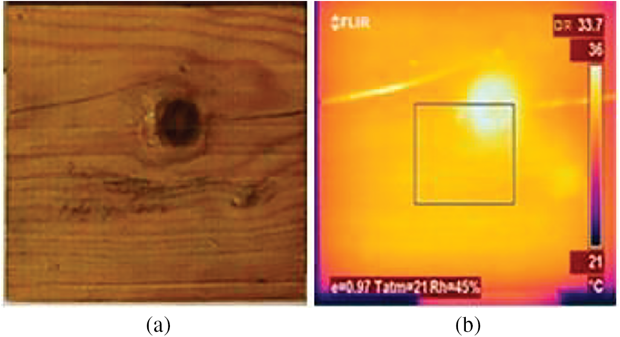
Figure 20: Picture (a) and a thermogram (b) of a pine sample indicating knot and crack. Reprinted from Reference [76]
IRT is suitable for detecting areas with varying water content in a swift and nondestructive manner. The comparison between the temperature increments in various areas of timber is conducted to determine the water content. Generally, active thermography is best suited to detect the moisture content in damp wood. This is because high water content rates tend to modify the thermal properties of the wood specimen. Furthermore, the thermal properties of timber are different from that of porous materials [77].
The decaying of wood is the greatest problem in timber structures. Oxygen, moisture, temperature, and sufficient food (wood) are the catalysts for the decaying process in wood. This decaying phenomenon is abundant in nature and prevalent in timber bridges [78]. As a result, it decreases the overall strength of the wood and adversely affects the structural integrity of timber structures [79]. According to Larson et al. [78], IRT can be effectively used to detect such as decay by focusing purely on detecting moisture in the wood. It can give us an idea if some part of timber elements has an excessive amount of moisture, but the downside is that it cannot give us a quantifiable measure of it. Furthermore, IRT equipment tends to be rather expensive, and the person operating it needs to be well-trained. Other factors, such as weather conditions and optimal survey time, must also be considered for IRT testing.
The time of conducting IRT is also crucial in detecting defects in timber elements consistent with other structures and materials. The moisture content in the wood may vary according to the climatic conditions and weather. Timber elements may have varying levels of heat absorption, which may induce errors from solar radiation. For this reason, Martínez et al. [80] recommend early morning inspection to gather better results. Also, their study suggests that temperature readings ranging from 5°C–40°C provide positive results for IRT analysis.
Some limitations of IRT include the level of penetration depth. IRT has been reported to be effective in decay identification in timber members, but it does not necessarily penetrate deep enough to generate solid and reliable results [81]. It is imperative that the properties of timber are assessed and detected early on before proceeding with any protection, repair, and rehabilitation works. IRT can also be used to determine various mechanical properties and density of timber members. Xin et al. [82] analyzed unsteady heat transfer mechanisms in timber specimens, where a cooling constant ‘Ve’ was proposed to accurately calculate the density and other mechanical properties of timber member specimens from ancient structures.
IRT thermal results hardly provide any information about the depth of discontinuities along a timber specimen. But, because the thermal conductivity of wood is relatively low, IRT allows the defects nearer the surface to be detected easily. It all depends on the thermal properties of the wood. The thermal conductivity of wood is mainly affected by factors such as moisture content, density, grain direction, irregularities like checks and knots, fibril angle, and ambient temperature. Usually, rot and decay are found in areas with higher moisture. Such defects significantly affect many mechanical properties of the timber [83].
3 Infrared Thermography on Building Structures
Buildings are also subject to various defects over their lifetime. Detection of such defects in buildings is essential and can be done using IRT. Reporting accurate IRT results often requires proper quantification of thermal images. This can be done using complex numerical algorithms which can turn thermal images into temperature readings. By analyzing these readings, inspectors can detect anomalies such as moisture, air leaks, cracks, and other problems that one cannot necessarily see through visual inspection. This is where IRT becomes very valuable because it aids in spotting those problems that would otherwise go undetected [84]. IRT can also be used to check if certain parts of a building have sufficient insulation or not. Additionally, it can also be applied for monitoring historic buildings and has many applications in the maintenance and preservation sector [85].
The use of IRT in evaluating the condition of buildings was thoroughly explored by some researchers. Titman [86] discusses various ways IRT can be used in buildings, one of which is investigating thermal bridging effects in buildings. Cold and hot air thermal bridging can be determined through proper IRT applications, and assessment of the severity of energy leakage can be done around doors, windows, and construction joints. Cracks and delaminations in structural elements can also affect the thermal performance of buildings and infrastructure. In addition, IRT can survey subsequent heat losses from such structural components inside a building and help improve the overall energy efficiency and mitigate running costs [87–89].
IRT for buildings is not only limited to solving energy leakage and efficiency problems but it can also be successfully used to address various issues related to moisture in structures. Wiggenhauser [90] claims that active thermography has proven to be very capable and reliable in identifying structure defects or moist regions in building elements and materials compared to quasi-static thermography.
The subsequent section of this paper discusses the potential applications of IRT for building components, particularly those made from reinforced concrete (RC) and masonry. Moreover, the further potential use of IRT for historical building preservation and maintenance is also touched upon in the subsequent chapters.
3.1 Defect Detection on Reinforced Concrete Members
Reinforced Concrete (RC) has been a popular building material used around the world for over a century. Buildings made from RC can get damaged and degrade over time due to various reasons, such as the environment, loading, and exposure conditions. Most countries require regular inspections to ensure the integrity of structures made from RC [91]. Common defects such as cracks and delaminations are often associated with the degradation and aging of RC building components. Early detection of cracks can allow proactive and preventive measures to reduce damage and possible failure of structural components such as beams, columns, and slabs [92]. However, visual inspection is typically employed initially to determine the onset of cracks during structural investigations. For such cases, IRT has been reported to be an efficient NDE technique to evaluate and assess the condition of RC structural components.
The use of IRT for evaluating concrete conditions was investigated by Sham et al. [93]. The authors used flash thermography to detect cracks on the surface of concrete specimens (Figs. 21 and 22). They reported the method to be very effective in detecting 0.5 to 1 mm width cracks on several concrete specimens. Moreover, they also go on to suggest using the active thermography method to locate cracks that are smaller than 0.5 mm.
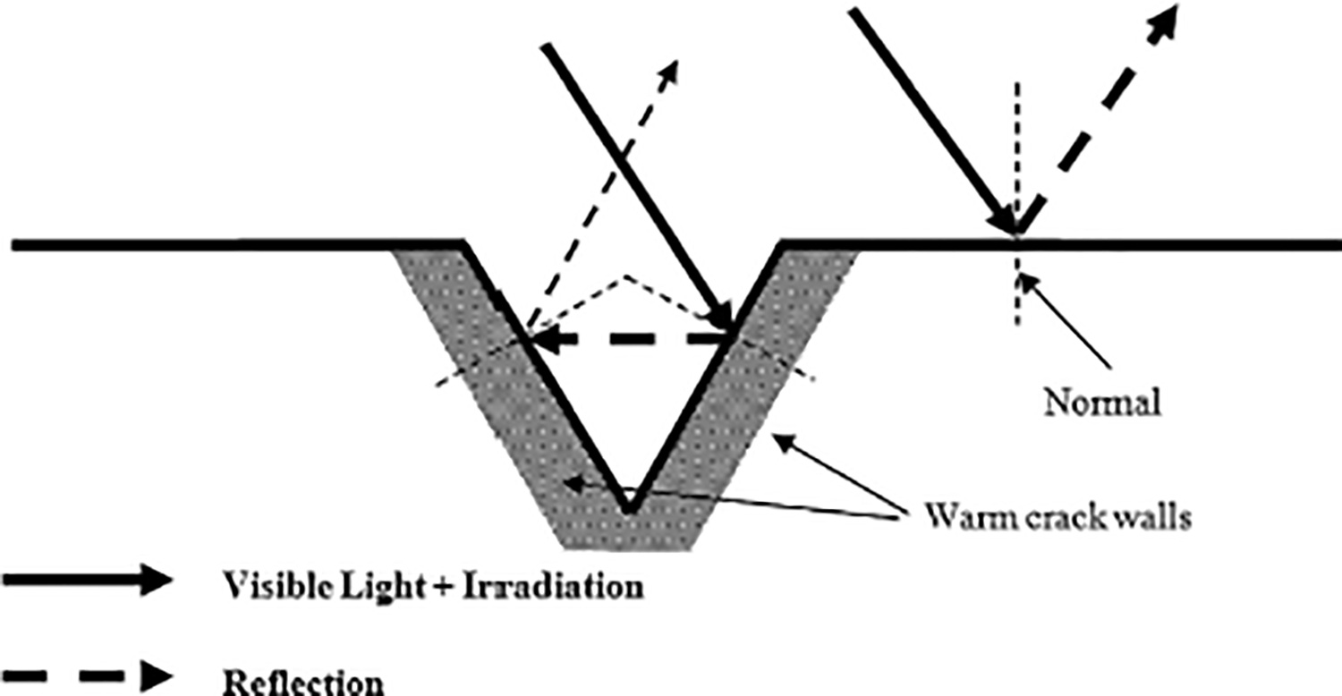
Figure 21: Reflectivity of radiation on cracked surface. Reprinted from Reference [93]
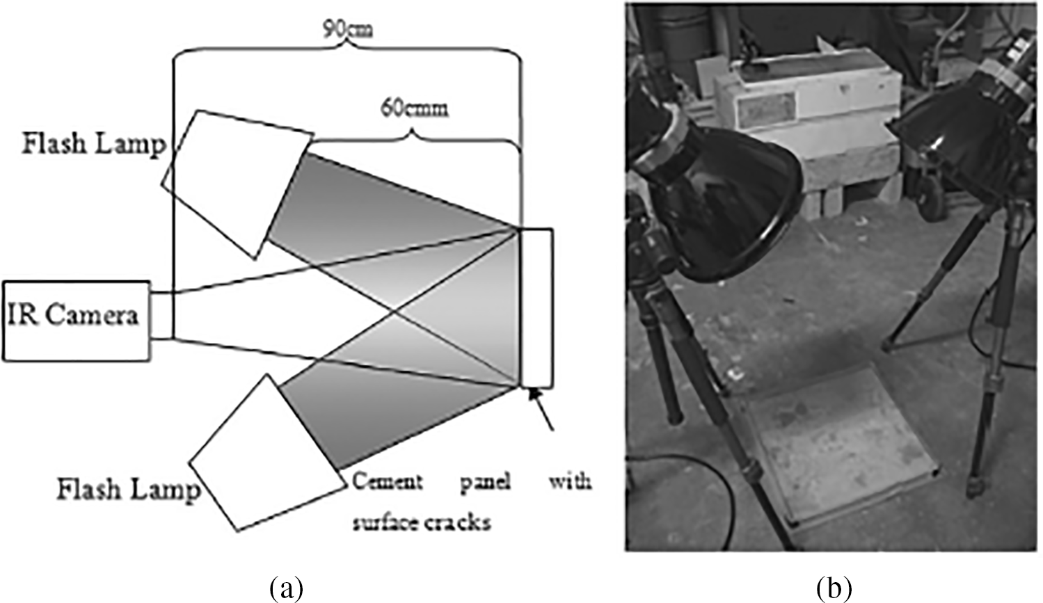
Figure 22: (a) Schematic diagram of surface crack detection by flash thermography, (b) experimental setup. Reprinted from Reference [93]
In another study, Seo et al. [10] performed a series of crack detection tests on scaled physical pillar structure models in a laboratory setting using active thermography. To validate their IRT results, strain gauge readings were used. The authors conclusively state that the failure time determined using thermograms coincided nicely with that measured through strain gauges. According to them, IRT imaging is a convenient method to assess the structure’s surface behavior, like the occurrence of initial cracks and the propagation of such cracks that lead up to failure.
The use of IRT for crack detection in concrete was reviewed by Mohan et al. [92]. In their paper, they present a comprehensive review of present state-of-the-art methods to detect cracks by image processing. They point out the importance of post-IRT survey data processing to enhance the thermograms and ultimately reduce the noise, which would lead to higher accuracy and efficiency in detecting defects and cracks on concrete structures. Pedram et al. [94] were among the researchers who studied the ability of IRT to detect defects in concrete components. They conducted a study that involved performing experiments on concrete slab samples with simulated voids embedded at various depths beneath the surface. They tried to detect the voids using a convection heat exchange mechanism to “initiate convective heating and cooling” of the slabs. Their results indicated a trend of thermal contrast with a distinct variation in defect depth. Furthermore, a mathematical model was created to establish a practical basis for decision-making processes for IRT.
Passive IRT has been focused on by many researchers in the past. Hiasa et al. [95] conducted a passive IRT test on an actual concrete structure at the University of Central Florida (Fig. 23). The IRT test was conducted at nighttime (around 9 pm), with the IR camera setup approximately 4 m from the structure with no angle. As shown in Fig. 24, the delaminated area was picked up in the thermogram, which appeared as a cold spot. This is caused by the test being conducted at nighttime, during the cooling cycle. The authors also validated the presence of the delaminated spot using hammer soundings later. In their study, the authors also tested the effectiveness of IR cameras when surveying at varying angles relative to an RC specimen. They report that IRT done at a perpendicular angle was less sensitive than when the IR camera is configured with a tilt at a certain angle.
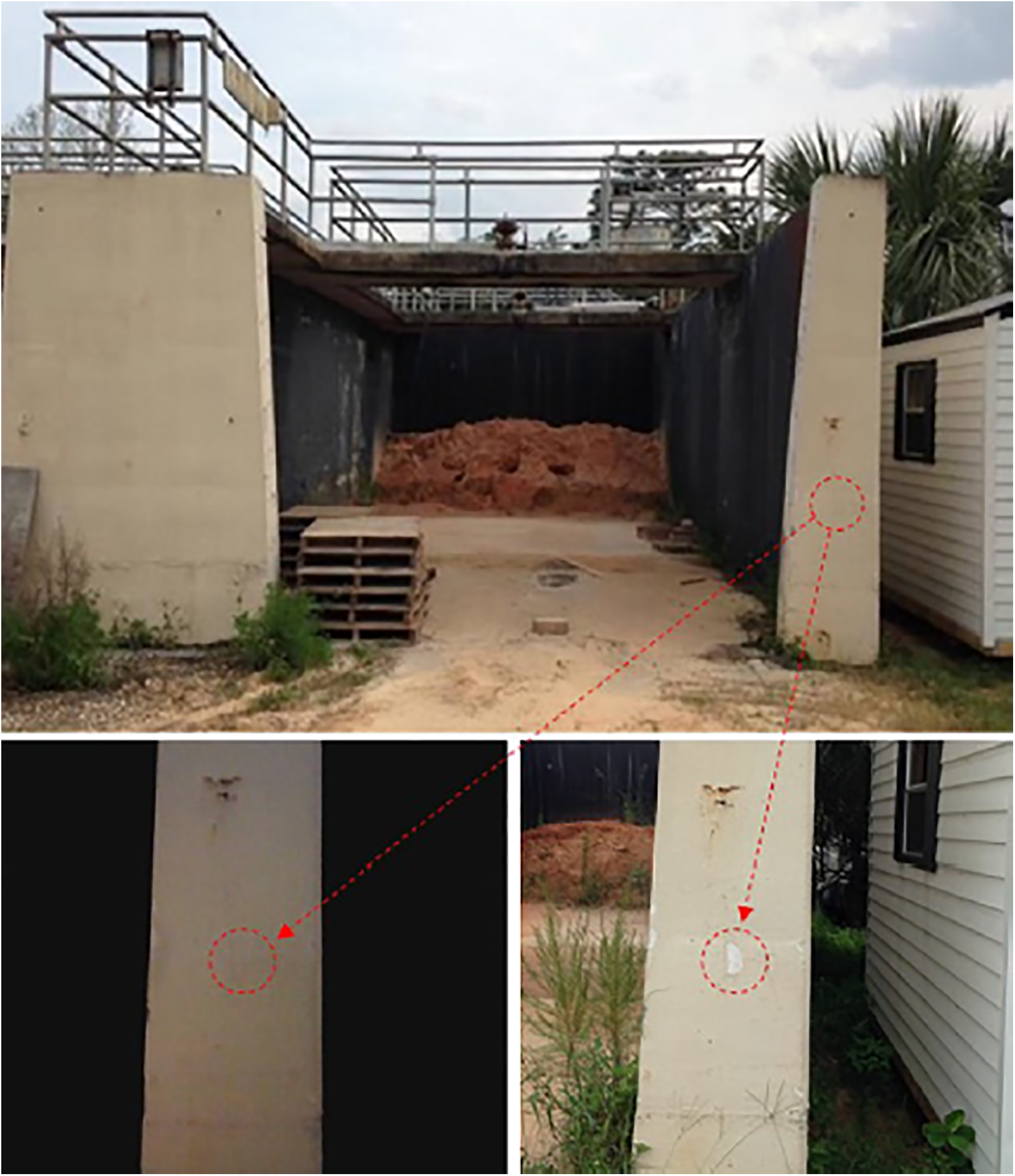
Figure 23: Concrete structure with delaminations. Reprinted from Reference [95]
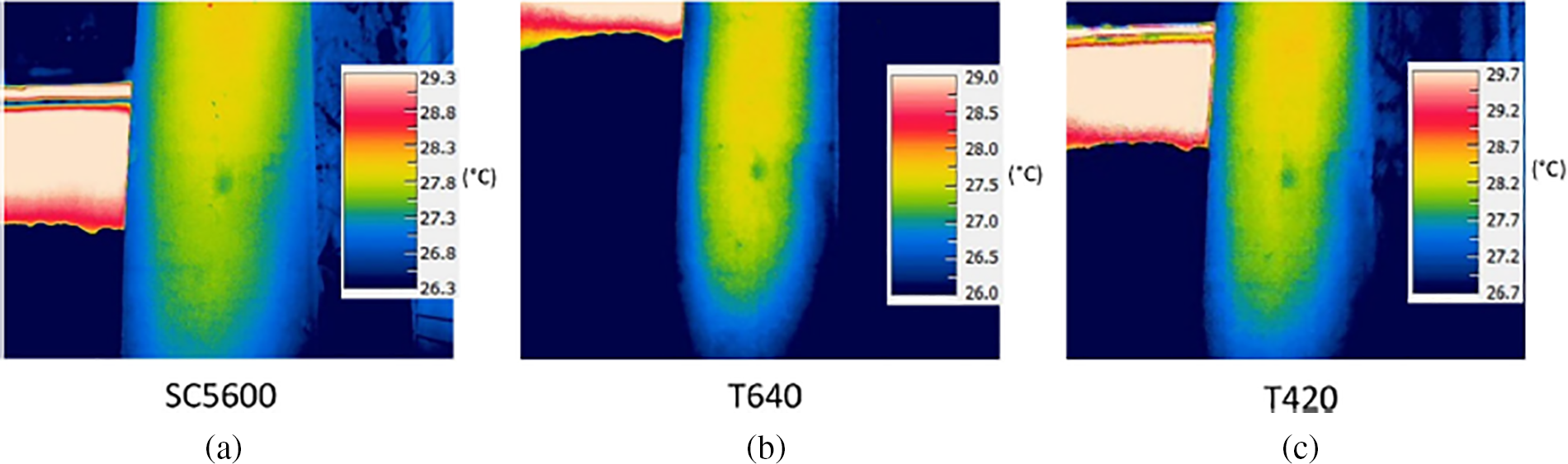
Figure 24: Raw IR images taken by different cameras. (a) SC5600, (b) T640, (c) T420. Reprinted from Reference [95]
Another study on the application of passive IRT on RC structures was done by Gonen et al. [14]. The researchers employed passive IRT on a reinforced concrete wall located in Turkey, which had a significantly delaminated area. Their objective was to locate the subsurface void behind the plaster on the RC wall in a quicker and easier method relative to a conventional tap test (Fig. 25).
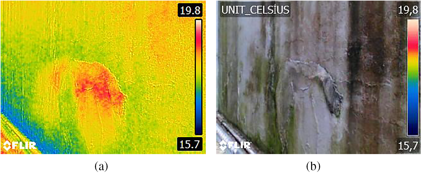
Figure 25: RC Retaining wall thermal image (a) and visible image (b). Reprinted from Reference [14]
The detection of corrosion in steel rebars using IRT was a topic that several researchers focused on. As mentioned in earlier sections, corrosion of steel rebars in RC structures leads to other defects, such as delamination and spalling. Baek et al. [37] integrated electromagnetic heat induction and IRT to detect steel rebar corrosion in RC members. They found a significant difference between corroded steel and non-corroded steel properties. Corroded steel has higher surface resistivity, resulting in a high peak IR intensity. Also, the heating rate becomes tentatively faster for highly corroded steel. Moreover, they found that induction heating as a form of IRT becomes less efficient for deeper defects. In another study, Szymanik et al. [91] could not detect the rebars that were located at depths greater than 20 mm in RC samples. Kobayashi et al. [96] also employed a combination of induction heating with IRT to discuss the effect of concrete covers on IR test results. They agree that a greater extent of corrosion causes a higher differential in temperature. The authors of the study state that the method is very effective for steel rebars of large diameter and small concrete cover. Therefore, detecting corrosion proactively in structures made from RC using IRT provides the best chance to predict the advent of degradation, which in turn can allow proper maintenance strategies to be put in place in a timely manner.
3.2 Infrared Thermography Applications on Masonry Structures and Historical Buildings
Masonry structures typically deteriorate slowly as they age. There are several causes, mainly thermal stress, seepage of water and moisture, natural forces, etc. The major defects that may occur on masonry elements may include voids, spalling, cracks, reinforcement deterioration, and variation in concrete compaction [97]. As an NDE method, IRT has proven to be very effective on masonry structures. They are commonly applied to quality control works, evaluating mortar pointing, and figuring out the presence of grout and solidity, among others.
In masonry structures, many internal defects that are generated in structural members are due to the temperature action within them. Most pathologies are based on the internal temperature and moisture [18] in those materials. Hence, it is essential to gain a good understanding of material temperature and to measure it to identify and classify various anomalies [98]. IRT does an excellent job in this role. It is also very efficient in determining the present state of masonry structures and various engineering properties. Not only is it instrumental in garnering qualitative information from condition surveys, but it is also productive in detecting internal features like voids or stress regions. Furthermore, as reported by some researchers, it can also be applied to determine subsurface anomalies, construction variations, moisture issues, air pockets and detecting internal cavities like ducts or chimneys [98].
Several studies have been carried out to explore the application of IRT for masonry structures. Schuller [98] reported that both active and passive approaches of IRT can be used for masonry elements surveys. He states that passive tests are beneficial to detect defects in masonry walls that lie deep under the surface, given that there is a sound temperature differential across the wall section, which in turn develops a steady state heat transfer condition. Different weather factors, such as sunlight and wind, also affect the temperature of the outer walls of buildings. Moreover, the assembly of walls and its constituent materials also influence the thermal behavior of the wall [99].
Some factors, such as the surrounding environment and test site conditions, impact the effectiveness of IRT surveys in masonry structures, as revealed by some studies. Clark et al. [16] conducted comprehensive IRT tests of various concrete and masonry bridges around the UK. The results they obtained were not satisfactory. They stated that the unfavorable weather and climatic conditions during the time IRT tests were done were the primary cause. However, qualitative delaminations were still visible in thermograms despite the imperfect survey conditions.
Cracks are common in masonry structures. They normally form in facades of masonry walls and buildings [100] (Fig. 26). They are mostly caused by temperature variations and other climatic conditions. IRT can be used to evaluate such cracks in masonry walls. Proper site conditions and timing allow IRT images to show cracks and defects clearly in masonry facades. The evaluation done using IRT thermograms is much more effective than merely visually inspecting defects from afar [101].
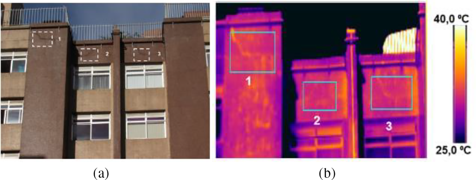
Figure 26: Study sample indicating cracks (a); thermogram showing detection of studied crack (b). Reprinted from Reference [100]
IRT is also productively employed for structural integrity checks and preservation of historical elements and buildings. In particular, IRT is utilized for those which are predominantly built out of masonry and in the form of load-bearing systems. Because IRT is an easy, non-contact evaluation method that provides reasonable qualitative data, IRT can be used as a very economical and swift method to determine shallow subsurface defects and anomalies in old and historical buildings. For instance, Nuzzo et al. [20] used the passive IRT technique to evaluate the structural condition of a masonry rose window in Italy. They were successful in identifying most of the fracture evidence that was developed on the window, even though some deeper-lying defects were hard to detect. They suggest that since IRT image interpretation is not that straightforward, other NDE methods could potentially be used in conjunction with IRT (like GPR or Ultrasonic Testing) to obtain better results. Such an approach can substantially help in conserving historic buildings. This approach is also consistent with suggestions provided by other scholars and researchers to maximize the effectiveness of IRT tests and successfully validate results. An extensive review of the combined application of IRT and GPR for building assessment was done by Garrido et al. [102]. Based on their review, the authors concluded that the combination of both inspection methods can allow a double verification of findings. Cotič et al. [103] also studied the use of both GPR and IRT on three-leaf masonry walls which were subjected to in-plane cyclic shear tests closely monitored using 3D digital image correlation technique. Their results revealed that the IR thermography method outperformed GPR in detecting surface-level seismic-related defects. However, GPR was far better at visualizing the masonry texture behind the wall’s plaster and performed well in detecting defects at deeper depths.
Another common defect in historical buildings is moisture damage. Masonry-built historical buildings are highly susceptible to moisture damage, which arises due to the capillary action of water from the ground. It is imperative to address this issue, which can be categorized as secondary to building structural damage. Moist patches generally leave out damp areas around which salt efflorescence is frequently generated, and as a result, further damage is done to the masonry elements [19]. Passive IRT was successfully implemented in detecting cracks and discontinuities in load-bearing walls of historic buildings in India [22]. The type of conservation treatments being used, information on developments, and various interventions in historical buildings were able to be identified using this technique.
Regarding the optimal time to conduct IRT surveys for external masonry elements, Turcanu et al. [12] suggest that it can be performed when it is overcast, like a cloudy day, or at night. Results from IRT surveys done during the day can be skewed due to the effects of shadows that may fall on external masonry units [104]. The authors believe that it allows IRT investigations to be done without the problem of temperature increases that occur due to incident solar radiation. It also, to some level, negates the impact of the absorbed solar energy on the thermograms, which would have presented a time lag of a few hours. Moreover, to undermine the influence of convective heat losses, the authors recommend that IRT tests be done at very low wind speeds.
One of the reasons why IRT is deemed a competent NDE method when it comes to the investigation of historical buildings is its capability to inspect large areas without any contact or damage. These days, qualitative tests are complemented by using more sophisticated methods which yield quantitative results [105].
4 Infrared Thermography Applications with Unmanned Aerial Vehicles (UAV)
Engineers and inspectors investigating and assessing the structural integrity of various civil structures and infrastructures face several challenges. For instance, in bridge inspections, there is a matter of having to control the traffic flow to conduct bridge top or deck inspections. Also, the use of snooper trucks to inspect under-bridge structural units incurs additional project costs and time. For buildings as well, there may be a few structural elements that may not be easily accessible to engineers to conduct proper condition assessments. For these reasons, the use of aerial vehicles such as drones and remote-controlled units has seen a rise in popularity.
Unmanned Aerial Vehicles (UAVs) are used for different types of applications within Civil Engineering. Particularly for construction engineering, UAVs have seen an increment of almost 240% in applications. The boom in the technological industry has aided in making UAVs more accessible and affordable to the public. Relative to traditional methods, UAV-based testing and survey operations perform much faster and result in excellent image spatial resolutions [106]. Aerial vehicles, or drones, are being used for the inspection of highways, buildings, roads, wind turbines, dams, cell towers, etc. Furthermore, in building structures, they are being implemented to monitor the building’s facades, roofs, mapping, survey, etc. [107]. UAVs also show great prospects for large-scale bridge inspection as well as pavement condition assessment. UAVs may be used to collect images, including infrared images, with bare minimum effort, cost, and overall time [108]. Moreover, UAVs can be used to conduct IRT tests, as outlined in the rest of this review article.
IRT tests can be performed by utilizing UAVs. When UAVs are equipped with thermal imaging systems, they can provide an excellent means to conduct IRT tests of civil infrastructures. Integrating thermography with drone technology enables the detection of structural and construction defects that may go undetected by the naked eye. Just as in laser scanners, drones can be effectively utilized to generate aerial thermal images of various parts of buildings, both on the interior and exterior sides. Hence, hot and cold spots can be assessed. It can also be used to map out places of water infiltration in buildings, such as leaks and regions of mold or rot in various masonry and timber elements that are not easily accessible. Detecting such regions in navigationally difficult areas can help building inspectors to accurately assess building elements before any severe damage is caused [107]. Moreover, UAVs can also be employed to evaluate thermal bridging effects in buildings and derive critical information regarding the overall energy consumption [106,109], efficiency, and performance of buildings. It can also be applied to a large urban scale, where temperature mapping of suburbs can be conducted [11,110] (Fig. 27). Fig. 28 displays the application of a UAV drone equipped with a thermal imaging system to map out thermal regions in a small building.
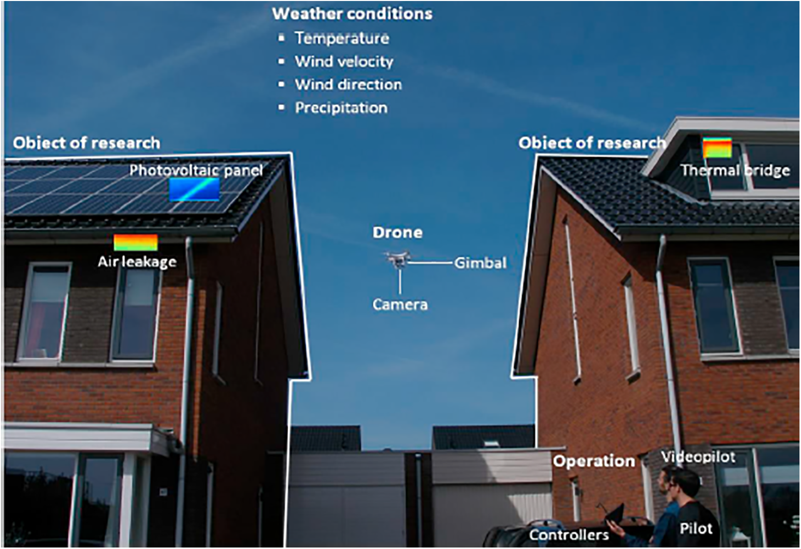
Figure 27: Outdoor building inspection by a drone. Reprinted from Reference [110]
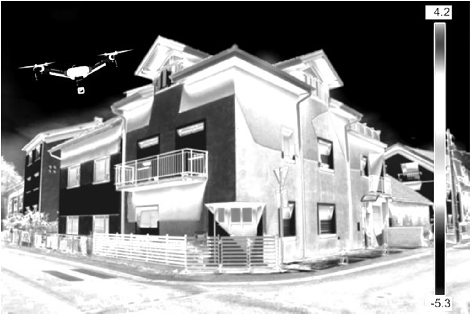
Figure 28: Thermal imaging using a drone. Reprinted from Reference [107]
The use of UAV-IRT to assess post-disaster damage instead of conventional methods was also investigated by scholars. In general, conventional methods of gathering information after natural disasters such as earthquakes, hurricanes, tornados, etc., involve field investigations. In such cases, several difficulties are present such as heavy workload, lack of timeliness, and extremely low efficiency. This is where structural damage assessment involving UAV-IRT can play a crucial role due to its sizeable spatial capacity and remote application abilities. Zhang et al. [111] put forward a framework that incorporates ultra-micro-oblique UAV and IRT imaging to automatically identify defects such as cracks in the external walls of buildings due to seismic damage. Analysis of thermal images obtained through IRT can be done to assess defects across the exterior of buildings. The proposed framework is shown in Fig. 29. The framework maps out core regions affected by an earthquake in 3D view. The swift IRT surveys of masonry or concrete elements further lead to proper assessment and prediction of the damage distribution in the buildings. Since this method is an automated technique, it proves to be much more convenient than traditional damage assessment methods.
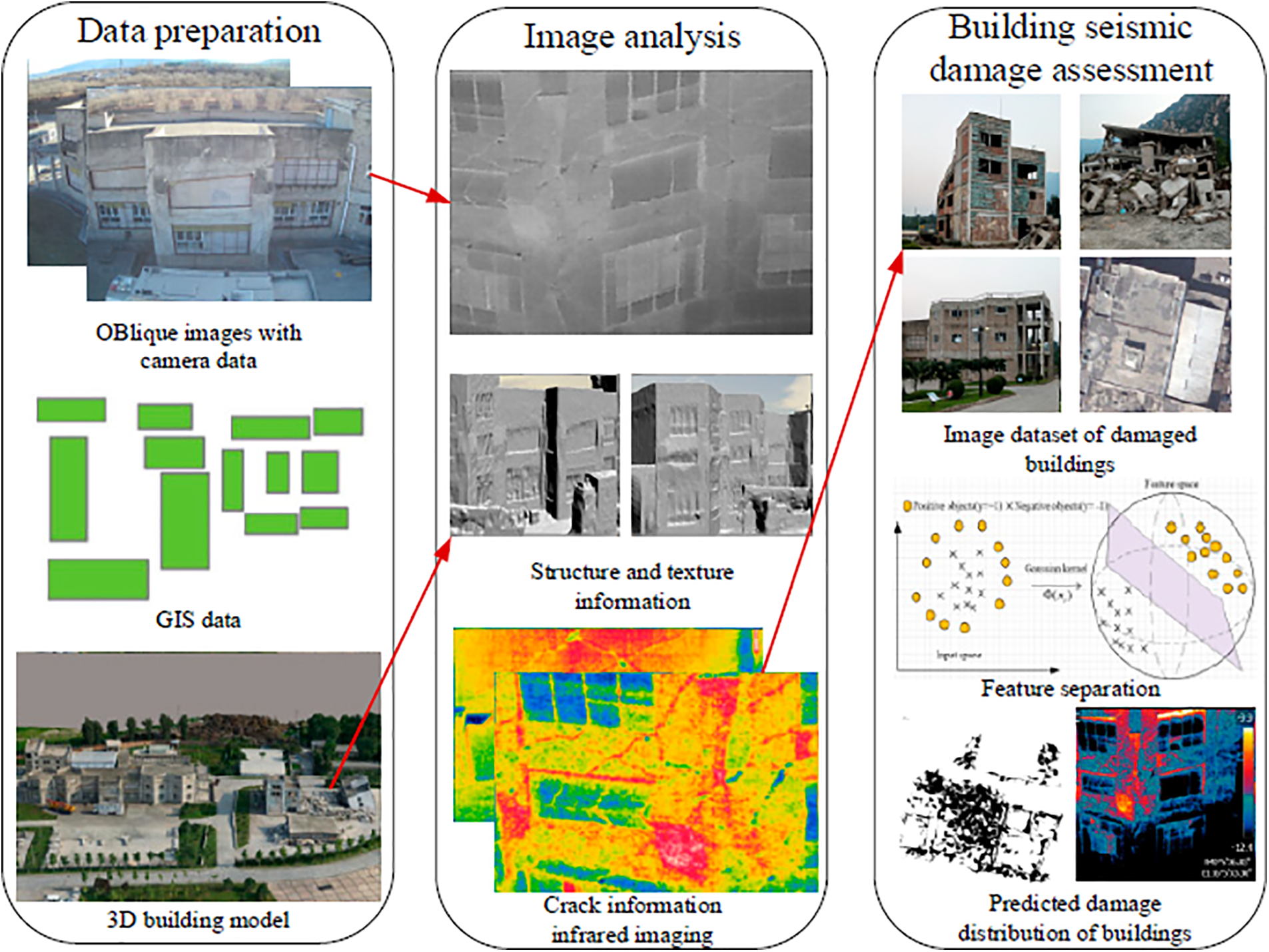
Figure 29: Proposed methodology framework. Reprinted from Reference [111]
Fig. 30 shows the results of UAV thermal imaging to assess seismic damage in buildings. The bottom image clearly shows the temperature differential, suggesting cracks around the exterior wall of the building.
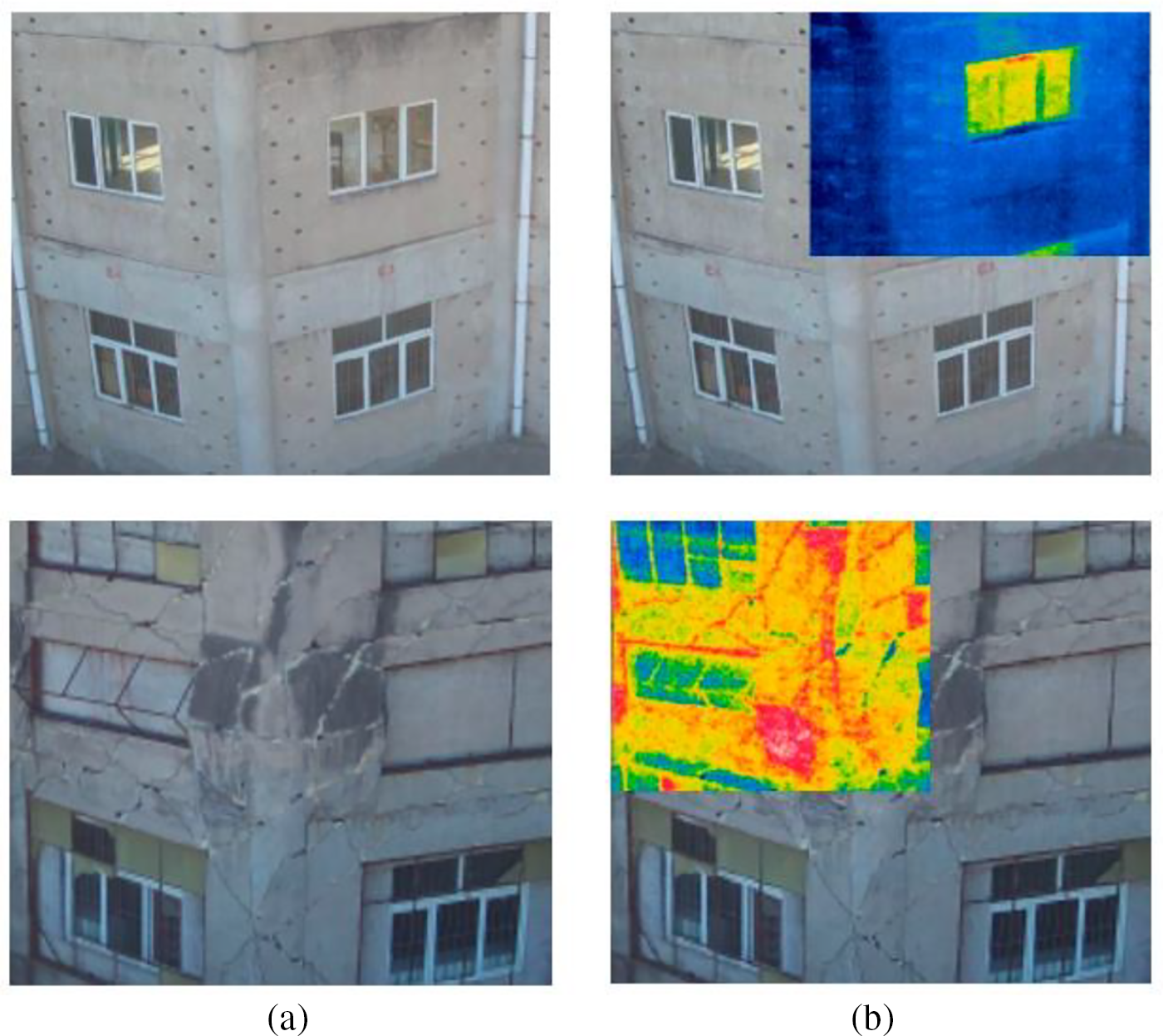
Figure 30: Wall crack damage assessment through thermal imaging. (a) Damaged building exterior, (b) thermal images of the damaged locations. Reprinted from Reference [111]
Comparison of the results of using UAV-IRT system and IRT was the topic of study for some researchers. Mavromatidis et al. [109] conducted an experiment by comparing the results of independent active IRT done in a laboratory setting and using a UAV equipped with an IR camera on a composite sample. A flash lamp was used, which gave out constant impulse IR radiation. The authors found the results of the two studies to be very comparable. However, they point out key issues that hinder the results while using the UAV-IRT system: the instability of the UAV system. According to the authors, this instability did not yield the best IR results, which was considered a significant problem.
Another experiment that had the objective of comparing the results of using UAV-IRT and IRT was done by Pant et al. [106]. Their results agree with this through their own findings. They also point out that a drone or UAV’s unexpected movements can render the results of the IRT test unfavorable, which can cause misinterpretation of data, irregular thermal profiling, and incorrect defect detection in structures. This is because the thermograms that are generally produced are often already “noisy,” which adds errors in the analysis of temperature differentials for the detection of defects. They suggest eliminating and minimizing such unwarranted motions in IRT data through digital video stabilization techniques during the test’s post-processing stage. Their paper also proposes a basic technique to ascertain the most feasible stabilization algorithm, which they believe to be an important step toward a complete operational UAV-IRT system.
UAV-IRT surveys are also affected by external factors such as wind, temperature, and precipitation [110]. These adverse factors encountered when using the UAV-IRT system were pointed out in a review paper published by Feroz et al. [112] (Fig. 31). The authors reviewed several papers associated with remote sensing techniques like visual imagery, IRT, LiDAR, etc., with UAVs for condition monitoring of bridges. Their article highlights many challenges related to UAV-based inspection procedures for bridge structures, including lack of standards for the inspection and equipment constraints such as battery life and payload limitations. Therefore, extensive planning and preparation must be done before IRT tests. Shen et al. [113] provide an excellent report on the use of UAV thermography for bridge deck evaluations. In their report, they recommend the best time and weather conditions for thermographic surveys using numerical simulations in Nebraska USA According to them, the wind speeds under which aerial IRT is deemed optimal are under 10 mph. Wind speeds higher than 15 mph led to instability issues and result in improper thermal readings.
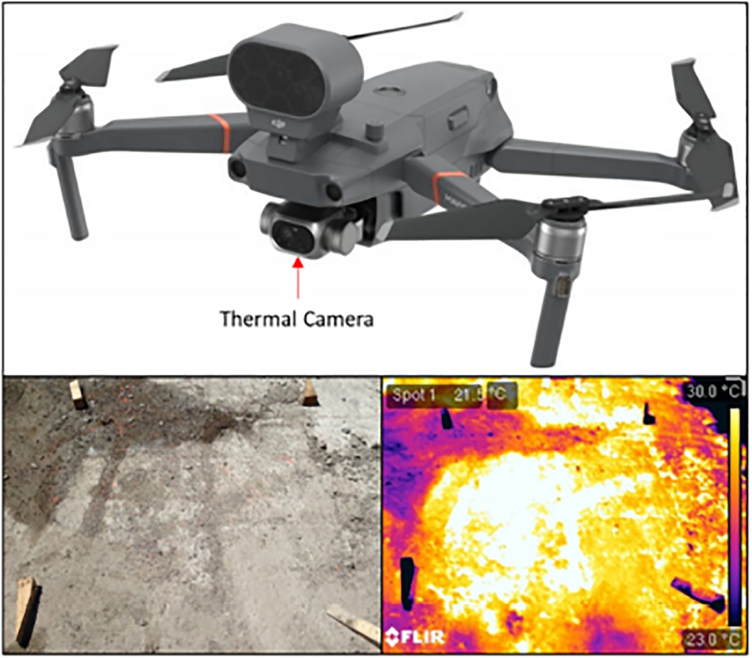
Figure 31: Typical UAV-IRT equipment and sample thermography data. Reprinted from Reference [112]
Other researchers focused on the incorporation of neural networks in the investigation process. Al Qurishee et al. [114] developed a computer model with the help of a convolutional neural network to automatically detect crack and non-crack defects in RC bridge girders with high accuracy. They report their model showing a 98% accuracy in detecting the defects. The authors used the features of machine learning to employ an excellent, progressive neural network to detect, classify, and characterize defects in some RC structures. They claim that such automated systems of inspection in civil infrastructures can often decrease the time it takes to conduct inspections, reduce mistakes during such inspections, and save some money for the project’s clients.
In a recent study by Frodella et al. [115], the use of UAV-IRT together with digital photogrammetry (DP) was investigated. The authors tried out this combination to successfully map out a cultural heritage site in Georgia. There, they were able to detect regions that were subjected to inclement weathering. This mostly included moisture zones that were connected to drainage networks, which contributed to the degradation of the heritage site. Escobar-Wolf et al. [116] evaluated the use of UAV-IRT in tandem with DP through field and lab tests on concrete slab specimens to detect delaminations with a fair deal of accuracy. They make the point that visible imagery and DP can aid in reducing false positive assessments during investigations. False positive assessments are regions of varying emissivity that are inaccurately picked out as areas of delaminations or subsurface defects.
Structural condition assessment is an urgent need for civil infrastructure in the 21st century, thus automated condition assessment technologies have gained popularity over the years. Among the static and dynamic assessment methods for condition assessment, Infrared Thermography (IRT) is a fast, accurate, and automated method taking advantage of advanced computer vision technology. The authors recognized the need for an organized literature review on the topic, and a detailed review of Infrared Thermography (IRT) applications on civil infrastructures has been presented in this paper. A brief introduction to the IRT working principles is provided, and subsequent application of the NDE method is highlighted for structures such as bridges and buildings made from various construction materials (reinforced concrete, steel, timber, fiber-reinforced polymer, and masonry). Through the review of recent publications, it can be concluded that IRT as an NDE technique has been an effective tool for proper condition assessment and structural health monitoring for civil infrastructures. It is a versatile method proven successful for various structures, components, and materials. Thermal imaging technology makes it possible to locate defects and anomalies in a myriad of materials and structures that would otherwise go unnoticed. This ability to identify issues, especially early on, can significantly enhance the safety and reliability of civil infrastructures and drastically reduce maintenance and rehabilitation costs.
Additionally, the non-destructive nature of IRT can allow for inspections to be conducted without invasive procedures, minimizing disruptions and consumption of the overall budget and significant downtime. Since it is a fully non-contact method, bridge deck inspections can be conducted without requiring lane closure and reducing traffic flow. IRT is also very productive in assessing issues such as fatigue cracks and stress concentrations in steel materials and elements made from steel. It is also important to note that IRT is beneficial in detecting air-filled debonds in FRP materials used for concrete structure strengthening applications and other composite structures. Moreover, its ability to detect moisture-related issues in timber elements helps inspectors quickly determine degradation areas such as rot and decay. For buildings, IRT is used to obtain essential information regarding thermal bridging and energy efficiency from structural elements. It can be stated that IRT demonstrates itself to be a robust method for construction site monitoring and assessing exterior elements such as facades of buildings. IRT can also be used to deduce facts regarding construction details in masonry and can easily be employed to check the structural integrity of historic structures. IRT applications with unmanned aerial vehicles (UAV-IRT) have also become more popular thanks to the remote sensing abilities of the method for accurate and efficient structural integrity checks and site monitoring. In summary, IRT proves to be an efficient and reliable technique that can be used in the civil engineering industry to assess the integrity of civil infrastructures. With the continued development and refinement of various IRT methods, it is most likely that this NDE method will become even more widely used in the maintenance and monitoring of civil infrastructure in the foreseeable future.
Acknowledgement: Not applicable.
Funding Statement: The authors did not have funding for this paper.
Author Contributions: Prabal Shrestha: Performed the review, wrote the manuscript. Onur Avci: Planned and organized the paper, performed the review, wrote the manuscript, performed editorial tasks, organized the tasks, served as a corresponding author. Sahabeddin Rifai: Detailed check of the text and references, editorial contribution. Feras Abla: Detailed check of the text and references, editorial contribution. Michael Seek: Editorial contribution. Karl Barth: Editorial contribution. Udaya Halabe: Editorial contribution. All authors reviewed the results and approved the final version of the manuscript.
Availability of Data and Materials: Available upon request.
Ethics Approval: Not applicable.
Conflicts of Interest: The authors declare no conflicts of interest to report regarding the present study.
References
1. Carnahan H. Pittsburgh bridge collapse emphasizes need for bridge repairs. J Protective Coat Linings. 2022;39:6–7. [Google Scholar]
2. Miami building collapse: what could have caused it? BBC News. 2021. Available from: https://www.bbc.com/news/world-us-canada-57651025. [Accessed 2024]. [Google Scholar]
3. Khanal S. Review of modern nondestructive testing techniques for civil infrastructure. Department of Civil and Environmental Engineering, West Virginia University: Morgantown, WV, USA; 2020. [Google Scholar]
4. Omar A, Moselhi O. Condition monitoring of reinforced concrete bridge decks: current practices and future perspectives. Curr Trends Civil Struct Eng. 2022;8(4):1–14. [Google Scholar]
5. Al Qurishee M, Wu W, Atolagbe B, El Said S, Ghasemi A. Non-destructive test application in civil infrastructure. Int Res J Eng Technol. 2019;6(12):2092–114. [Google Scholar]
6. Omar T, Nehdi ML. Application of passive infrared thermography for the detection of defects in concrete bridge elements. In: Proceedings of the International Conference of the Transporation Association of Canada, 2016; Toronto, ON, Canada; p. 22–8. [Google Scholar]
7. Mulaveesala R, Dua G, Arora V. Applications of infrared thermography for non-destructive characterization of concrete structures. In: Advances in structural health monitoring. London, UK: IntechOpen; 2019. [Google Scholar]
8. Matovu MJ, Farhidzadeh A, Salamone S. Damage assessment of steel-plate concrete composite walls by using infrared thermography: a preliminary study. J Civ Struct Health Monit. 2016;6:303–13. doi:10.1007/s13349-016-0169-4. [Google Scholar] [CrossRef]
9. Omar T, Nehdi ML, Zayed T. Infrared thermography model for automated detection of delamination in RC bridge decks. Constr Build Mater. 2018;168(11):313–27. doi:10.1016/j.conbuildmat.2018.02.126. [Google Scholar] [CrossRef]
10. Seo H, Choi H, Park J, Park J, Lee IM. Crack detection in pillars using infrared thermographic imaging. Geotech Test J. 2017;40(3):371–80. doi:10.1520/GTJ20150245. [Google Scholar] [CrossRef]
11. Tejedor B, Lucchi E, Nardi I. Application of qualitative and quantitative infrared thermography at urban level: potential and limitations. In: Lecture notes in civil engineering. Berlin/Heidelberg, Germany: Springer Science and Business Media Deutschland GmbH; 2022. p. 3–19. [Google Scholar]
12. Turcanu EF, Ciocan V, Verdes M, Luciu RS, Bǎlan MC, Hudisteanu SV, et al. IR thermography applied in church heritage conservation. IOP Conf Ser: Mater Sci Eng. 2019;586:012041. [Google Scholar]
13. Ciampa F, Mahmoodi P, Pinto F, Meo M. Recent advances in active infrared thermography for non-destructive testing of aerospace components. Sensors. 2018;18(2):609. doi:10.3390/s18020609. [Google Scholar] [PubMed] [CrossRef]
14. Gonen S, Tonga B, Catbas FN. Rapid non-contact visual scanning of structures using infrared thermography. In: Proceedings of the 12th International Congress on Advances in Civil Engineering, 2016 Sep 21–23; Istanbul, Turkey. [Google Scholar]
15. Cannard H, Mahrez M, Perrin T, Muzet V, Prybyla D, Brachelet F. The use of infrared thermography for defects detection on reinforced concrete bridges. In: Proceedings of the 12th Quantitative InfraRed Thermography (QIRT2014), 2014 Jul 7–11; Bordeaux, France; p. 7–11. [Google Scholar]
16. Clark MR, Mccann DM, Forde MC. Application of infrared thermography to the non-destructive testing of concrete and masonry bridges. NDT&E Int. 2003;36(4):265–75. doi:10.1016/S0963-8695(02)00060-9. [Google Scholar] [CrossRef]
17. Watase A, Birgul R, Hiasa S, Matsumoto M, Mitani K, Catbas FN. Practical identification of favorable time windows for infrared thermography for concrete bridge evaluation. Constr Build Mater. 2015;101(1–2):1016–30. doi:10.1016/j.conbuildmat.2015.10.156. [Google Scholar] [CrossRef]
18. Barreira E, Almeida RMSF, Delgado JMPQ. Infrared thermography for assessing moisture related phenomena in building components. Constr Build Mater. 2016;110(7):251–69. doi:10.1016/j.conbuildmat.2016.02.026. [Google Scholar] [CrossRef]
19. Grinzato E, Bison PG, Marinetti S. Monitoring of ancient buildings by the thermal method. J Cult Herit. 2002;3(1):21–9. doi:10.1016/S1296-2074(02)01159-7. [Google Scholar] [CrossRef]
20. Nuzzo L, Calia A, Liberatore D, Masini N, Rizzo E. Integration of ground-penetrating radar, ultrasonic tests and infrared thermography for the analysis of a precious medieval rose window. Adv Geosci. 2010;24:69–82. doi:10.5194/adgeo-24-69-2010. [Google Scholar] [CrossRef]
21. Tomita K, Chew MYL. A review of infrared thermography for delamination detection on infrastructures and buildings. Sensors. 2022;22:423. doi:10.3390/s22020423. [Google Scholar] [PubMed] [CrossRef]
22. Sakalle R, Verma S. Condition assessment of the historical building of Bhopal, (India) using passive infrared thermography. Int J Adv Res Eng Technol. 2021;12:243–54. [Google Scholar]
23. Chung Y, Shrestha R, Lee S, Kim W. Thermographic inspection of internal defects in steel structures: analysis of signal processing techniques in pulsed thermography. Sensors. 2020;20:6015. doi:10.3390/s20216015. [Google Scholar] [PubMed] [CrossRef]
24. Antolis C, Rajic N. Optical lock-in thermography for structural health monitoring—a study into infrared detector performance. Procedia Eng. 2017;188(4):471–8. doi:10.1016/j.proeng.2017.04.510. [Google Scholar] [CrossRef]
25. Noszczyk P, Nowak H. Inverse contrast in non-destructive materials research by using active thermography. Materials. 2019;12(5):835. doi:10.3390/ma12050835. [Google Scholar] [PubMed] [CrossRef]
26. Usamentiaga R, Venegas P, Guerediaga J, Vega L, Molleda J, Bulnes FG. Infrared thermography for temperature measurement and non-destructive testing. Sensors. 2014;14:12305–48. doi:10.3390/s140712305. [Google Scholar] [PubMed] [CrossRef]
27. Khedmatgozar Dolati SS, Caluk N, Mehrabi A. Non-destructive testing applications for steel bridges. Appl Sci. 2021;11:9757. doi:10.3390/app11209757. [Google Scholar] [CrossRef]
28. He JH, Liu DP, Chung CH, Huang HH. Infrared thermography measurement for vibration-based structural health monitoring in low-visibility harsh environments. Sensors. 2020;20:7067. doi:10.3390/s20247067. [Google Scholar] [PubMed] [CrossRef]
29. Pazhoohesh M, Zhang C, Hammad A, Taromi Z, Razmjoo A. Infrared thermography for a quick construction progress monitoring approach in concrete structures. Archit Struct Constr. 2021;1:91–106. doi:10.1007/s44150-021-00008-7. [Google Scholar] [CrossRef]
30. Senthilkumar M, Sreekanth TG, Manikanta Reddy S. Nondestructive health monitoring techniques for composite materials: a review. Polym Polym Compos. 2021;29:528–40. [Google Scholar]
31. Alampalli J. Use of NDT technologies in US bridge inspection practice. Mater Eval. 2009;67(11):1236–46. [Google Scholar]
32. Coleman ZW, Schindler AK. Investigation of ground-penetrating radar, impact echo, and infrared thermography methods to detect defects in concrete bridge decks. Transport Res Rec: J Transport Res Board. 2022;36(2):65. doi:10.1177/03611981221101027. [Google Scholar] [CrossRef]
33. Vaghefi K, Melo e Silva HA, Harris DK, Ahlborn TM. Application of thermal IR imagery for concrete bridge inspection. In: PCI National Bridge Conference, 2011 Oct; Salt Lake City, UT, USA: PCI/NBC; p. 1–12. [Google Scholar]
34. Sirca GF, Adeli H. Infrared thermography for detecting defects in concrete structures. J Civ Eng Manag. 2018;24(7):508–15. doi:10.3846/jcem.2018.6186. [Google Scholar] [CrossRef]
35. Hiasa S, Birgul R, Necati Catbas F. A data processing methodology for infrared thermography images of concrete bridges. Comput Struct. 2017;190:205–18. doi:10.1016/j.compstruc.2017.05.011. [Google Scholar] [CrossRef]
36. Hiasa S, Catbas FN, Matsumoto M, Mitani K. Monitoring concrete bridge decks using infrared thermography with high speed vehicles. Struct Monit Maint. 2016;3(3):277–96. doi:10.12989/smm.2016.3.3.277. [Google Scholar] [CrossRef]
37. Baek S, Xue W, Feng MQ, Kwon S. Nondestructive corrosion detection in RC through integrated heat induction and IR thermography. J Nondestr Eval. 2012;31(2):181–90. doi:10.1007/s10921-012-0133-0. [Google Scholar] [CrossRef]
38. Janků M, Březina I, Grošek J. Use of infrared thermography to detect defects on concrete bridges. Procedia Eng. 2017;190:62–9. doi:10.1016/j.proeng.2017.05.308. [Google Scholar] [CrossRef]
39. Mac VH, Tran QH, Huh J, Doan NS, Kang C, Han D. Detection of delamination with various width-to-depth ratios in concrete bridge deck using passive IRT: limits and applicability. Materials. 2019;12:3996. doi:10.3390/ma12233996. [Google Scholar] [PubMed] [CrossRef]
40. Oh T, Kee S-H, Arndt RW, Popovics JS, Zhu J. Comparison of NDT methods for assessment of a concrete bridge deck. J Eng Mech. 2013;139:305–14. [Google Scholar]
41. Pozzer S, Dalla Rosa F, Pravia ZMC, Rezazadeh Azar E, Maldague X. Long-term numerical analysis of subsurface delamination detection in concrete slabs via infrared thermography. Appl Sci. 2021;11:4323. doi:10.3390/app11104323. [Google Scholar] [CrossRef]
42. Kee S-H, Oh T, Popovics JS, Arndt RW, Zhu J. Nondestructive bridge deck testing with air-coupled impact-echo and infrared thermography. J Bridge Eng. 2012;17:928–39. doi:10.1061/(ASCE)BE.1943-5592.0000350. [Google Scholar] [CrossRef]
43. Washer G, Asce M, Fenwick R, Bolleni N. Effects of solar loading on infrared imaging of subsurface features in concrete. J Bridge Eng. 2010;15(4):384–90. doi:10.1061/(ASCE)BE.1943-5592.0000117. [Google Scholar] [CrossRef]
44. Huh J, Tran QH, Lee JH, Han D, Ahn JH, Yim S. Experimental study on detection of deterioration in concrete using infrared thermography technique. Adv Mater Sci Eng. 2016;2016:1053856. [Google Scholar]
45. Rocha JHA, Póvoas YV. Infrared thermography as a non-destructive test for the inspection of reinforced concrete bridges: a review of the state of the art. Rev ALCONPAT. 2017;7:200–14. [Google Scholar]
46. Huh J, Mac VH, Tran QH, Lee KY, Lee JI, Kang C. Detectability of delamination in concrete structure using active infrared thermography in terms of signal-to-noise ratio. Appl Sci. 2018;8(10):1986. doi:10.3390/app8101986. [Google Scholar] [CrossRef]
47. Maser KR. Integration of ground penetrating radar and infrared thermography for bridge deck condition evaluation. In: Non-Destructive Testing in Civil Engineering Conference, 2009 Jun 30–Jul 3; Nantes, France. [Google Scholar]
48. Chun PJ, Hayashi S. Development of a concrete floating and delamination detection system using infrared thermography. IEEE/ASME Trans Mechatron. 2021;26:2835–44. doi:10.1109/TMECH.2021.3106867. [Google Scholar] [CrossRef]
49. Hiasa S, Necati Catbas F, Matsumoto M, Mitani K. Considerations and issues in the utilization of infrared thermography for concrete bridge inspection at normal driving speeds. J Bridge Eng. 2017;22(11):04017101. doi:10.1061/(ASCE)BE.1943-5592.0001124. [Google Scholar] [CrossRef]
50. Abdel-Qader I, Yohali S, Abudayyeh O, Yehia S. Segmentation of thermal images for non-destructive evaluation of bridge decks. NDT&E Int. 2008;41(5):395–405. doi:10.1016/j.ndteint.2007.12.003. [Google Scholar] [CrossRef]
51. Solovyov L, Solovyov A, Fedorenko V. Thermal method for detecting fatigue cracks in welded steel bridges under random loads. Transp Res Procedia. 2022;61:588–93. doi:10.1016/j.trpro.2022.01.095. [Google Scholar] [CrossRef]
52. Broberg P. Surface crack detection in welds using thermography. NDT&E Int. 2013;57:69–73. doi:10.1016/j.ndteint.2013.03.008. [Google Scholar] [CrossRef]
53. Ranjit S, Kang K, Kim W. Investigation of lock-in infrared thermography for evaluation of subsurface defects size and depth. Int J Precis Eng Manuf. 2015;16(11):2255–64. doi:10.1007/s12541-015-0290-z. [Google Scholar] [CrossRef]
54. Chulkov AO, Vavilov VP. Comparing thermal stimulation techniques in infrared thermographic inspection of corrosion in steel. IOP Conf Ser: Mater Sci Eng. 2015;81(1):012100. [Google Scholar]
55. Moyseychik EA, Vavilov VP, Kuimova MV. Infrared thermographic testing of steel structures by using the phenomenon of heat release caused by deformation. J Nondestr Eval. 2018;37(2):28. doi:10.1007/s10921-018-0482-4. [Google Scholar] [CrossRef]
56. Yu X, Yu B. State of practice of NDE technologies in bridge inspection. Multi-agent sustainable water decision theory (MUSTnexus of water, road, and hierarchic social contractual systems view project; 2015. Available from: https://www.researchgate.net/profile/Bill-Yu-2/publication/267999815_STATE_OF_PRACTICE_OF_NDE_TECHNOLOGIES_IN_BRIDGE_INSPECTION/links/5601823e08aed985182722bf/STATE-OF-PRACTICE-OF-NDE-TECHNOLOGIES-IN-BRIDGE-INSPECTION.pdf. [Accessed 2024]. [Google Scholar]
57. Sakagami T, Izumi Y, Shiozawa D, Fujimoto T, Mizokami Y, Hanai T. Nondestructive evaluation of fatigue cracks in steel bridges based on thermoelastic stress measurement. Procedia Struct Integr. 2016;2:2132–9. doi:10.1016/j.prostr.2016.06.267. [Google Scholar] [CrossRef]
58. Sakagami T, Mizokami Y, Shiozawa D, Fujimoto T, Izumi Y, Hanai T, et al. Verification of the repair effect for fatigue cracks in members of steel bridges based on thermoelastic stress measurement. Eng Fract Mech. 2017;183(62):1–12. doi:10.1016/j.engfracmech.2017.05.024. [Google Scholar] [CrossRef]
59. Netzelmann U, Walle G, Lugin S, Ehlen A, Bessert S, Valeske B. Induction thermography: principle, applications and first steps towards standardization. Quant InfraRed Thermogr J. 2016;13(2):170–81. doi:10.1080/17686733.2016.1145842. [Google Scholar] [CrossRef]
60. Oswald-Tranta B. Induction thermography for surface crack detection and depth determination. Appl Sci. 2018;8(2):257. doi:10.3390/app8020257. [Google Scholar] [CrossRef]
61. Zenzinger G, Bamberg J, Dumm M, Nutz P. Crack detection using eddy Therm. AIP Conf Proc. 2005;760(1):1646–53. [Google Scholar]
62. Starman S, Matz V. Automated system for crack detection using infrared thermographic testing. In: Proceedings of the International Conference on Non Destructive Evaluation for Steel and Allied Industries-NDESAI 2011, 2011 Dec 2–3; SNTI Auditorium Jamshedpur, India. [Google Scholar]
63. Yumnam M, Gupta H, Ghosh D, Jaganathan J. Inspection of concrete structures externally reinforced with FRP composites using active infrared thermography: a review. Constr Build Mater. 2021;310:125265. doi:10.1016/j.conbuildmat.2021.125265. [Google Scholar] [CrossRef]
64. Halabe UB, Dutta SS. Quantitative characterization of debond size in FRP wrapped concrete cylindrical columns using infrared thermography. In: Proceedings of the Fourth Japan-US Symposium on Emerging NDE Capabilities for a Safer World, 2010 Jun 7–11; Maui Island, HI, USA; p. 64–8. [Google Scholar]
65. Halabe UB, AlQennah H, GangaRao HVS, Klinkhachorn P, Sazonov ES. Nondestructive evaluation of FRP composite bridge components using infrared thermography. AIP Conf Proc. 2003;615:1303–9. [Google Scholar]
66. Shardakov IN, Shestakov AP, Bykov AA. Delamination of carbon-fiber strengthening layer from concrete beam during deformation (infrared thermography). Frattura Ed Integrita Strutturale. 2016;10:331–8. doi:10.3221/IGF-ESIS.38.43. [Google Scholar] [CrossRef]
67. Foudazi A, Donnell KM, Ghasr MT. Application of active microwave thermography to delamination detection. In: 2014 IEEE International Instrumentation and Measurement Technology Conference (I2MTC), 2014, IEEE; p. 1567–71. [Google Scholar]
68. Halabe UB, Dutta SS, GangaRao HVS. Infrared thermographic and radar testing of polymer-wrapped composites. Mater Eval. 2010;68(4):447–51. [Google Scholar]
69. Hing CLC, Halabe UB. Nondestructive testing of GFRP bridge decks using ground penetrating radar and infrared thermography. J Bridge Eng, ASCE. 2010;15(4):391–8. doi:10.1061/(ASCE)BE.1943-5592.0000066. [Google Scholar] [CrossRef]
70. Halabe UB. Nondestructive evaluation of fiber reinforced polymer composite structures using infrared thermography and digital tap testing. West Virginia University: Morgantown, WV, USA; 2021. [Google Scholar]
71. Kavi J, Halabe UB. Detection of buried pipelines transporting hot fluids using infrared thermography. J Multidiscip Eng Sci Technol. 2018;5(11):9060–7. doi:10.31224/osf.io/nm6s3. [Google Scholar] [CrossRef]
72. Pitarma R, Crisóstomo J, Pereira L. Detection of wood damages using infrared thermography. Procedia Comput Sci. 2019;155(15):480–6. doi:10.1016/j.procs.2019.08.067. [Google Scholar] [CrossRef]
73. Ou FL, Weller C. An overview of timber bridges. Transp Res Rec. 1986;1053:1–2. [Google Scholar]
74. Kandemir-Yucel A, Tavukcuoglu A, Caner-Saltik EN. In situ assessment of structural timber elements of a historic building by infrared thermography and ultrasonic velocity. Infrared Phys Technol. 2007;49(3):243–8. doi:10.1016/j.infrared.2006.06.012. [Google Scholar] [CrossRef]
75. Sandak J, Sandak A. Using various infrared techniques for assessing timber structures. Int J Comput Methods Exp Meas. 2017;5:858–71. doi:10.2495/CMEM. [Google Scholar] [CrossRef]
76. Crisóstomo J, Pitarma R. The importance of emissivity on monitoring and conservation of wooden structures using infrared thermography. In: Advances in structural health monitoring. London, UK: IntechOpen; 2019. [Google Scholar]
77. Ludwig N, Redaelli V, Rosina E, Augelli F. Moisture detection in wood and plaster by IR thermography. Infrared Phys Technol. 2004;46(1–2):161–6. doi:10.1016/j.infrared.2004.03.020. [Google Scholar] [CrossRef]
78. Larson T, Seavey R. Inspection of timber bridges. 2002. Available from: https://hdl.handle.net/11299/882. [Accessed 2024]. [Google Scholar]
79. Sandak A, Riggio M, Sandak J. Non destructive characterization of wooden members using near infrared spectroscopy. Adv Mat Res. 2013;778:328–34. doi:10.4028/www.scientific.net/AMR.778.328. [Google Scholar] [CrossRef]
80. Martínez I, Martínez E. Qualitative timber structure assessment with passive IR thermography. Case study of sources of common errors. Case Stud Constr Mater. 2022;16:e00789. [Google Scholar]
81. Wacker JP, Senalik CA, Wang J. Effectiveness of several NDE technologies in detecting moisture pockets and artificial defects in sawn timber and glulam. In: World Conference on Timer Engineering, WCTE, 2016 Aug 22–25; Vienna, Austria; p. 22–5. [Google Scholar]
82. Xin Z, Guan C, Zhang H, Yu Y, Liu F, Zhou L, et al. Assessing the density and mechanical properties of ancient timber members based on the active infrared thermography. Constr Build Mater. 2021;304(6):124614. doi:10.1016/j.conbuildmat.2021.124614. [Google Scholar] [CrossRef]
83. Riggio M, Sandak J, Franke S. Application of imaging techniques for detection of defects, damage and decay in timber structures on-site. Constr Build Mater. 2015;101(1):1241–52. doi:10.1016/j.conbuildmat.2015.06.065. [Google Scholar] [CrossRef]
84. Grinzato E, Vavilov V, Kauppinen T. Quantitative infrared thermography in buildings. Energy Build. 1998;29(1):1–9. doi:10.1016/S0378-7788(97)00039-X. [Google Scholar] [CrossRef]
85. Kylili A, Fokaides PA, Christou P, Kalogirou SA. Infrared thermography (IRT) applications for building diagnostics: a review. Appl Energy. 2014;134:531–49. doi:10.1016/j.apenergy.2014.08.005. [Google Scholar] [CrossRef]
86. Titman DJ. Applications of thermography in non-destructive testing of structures. NDT&E Int. 2001;34(2):149–54. doi:10.1016/S0963-8695(00)00039-6. [Google Scholar] [CrossRef]
87. Hart JM. A practical guide to infra-red thermography for building surveys. UK: Building Research Establishment; 1991. [Google Scholar]
88. Pedram M, Taylor S, Hamill G, Robinson D, OBrien EJ, Uddin N. Experimental evaluation of heat transition mechanism in concrete with subsurface defects using infrared thermography. Constr Build Mater. 2022;360:129531. doi:10.1016/j.conbuildmat.2022.129531. [Google Scholar] [CrossRef]
89. Zalewski L, Lassue S, Rousse D, Boukhalfa K. Experimental and numerical characterization of thermal bridges in prefabricated building walls. Energy Convers Manag. 2010;51:2869–77. doi:10.1016/j.enconman.2010.06.026. [Google Scholar] [CrossRef]
90. Wiggenhauser H. Active IR-applications in civil engineering. Infrared Phys Technol. 2002;43(3–5):233–8. [Google Scholar]
91. Szymanik B, Frankowski PK, Chady T, Chelliah CRAJ. Detection and inspection of steel bars in reinforced concrete structures using active infrared thermography with microwave excitation and eddy current sensors. Sensors. 2016;16:234. doi:10.3390/s16020234. [Google Scholar] [PubMed] [CrossRef]
92. Mohan A, Poobal S. Crack detection using image processing: a critical review and analysis. Alex Eng J. 2018;57:787–98. doi:10.1016/j.aej.2017.01.020. [Google Scholar] [CrossRef]
93. Sham FC, Chen N, Long L. Surface crack detection by flash thermography on concrete surface. Insight: Non-Destruct Test Cond Monit. 2008;50:240–3. doi:10.1784/insi.2008.50.5.240. [Google Scholar] [CrossRef]
94. Pedram M, Taylor S, Robinson D, Hamill G, O’Brien E, Uddin N. Experimental investigation of subsurface defect detection in concretes by infrared thermography and convection heat exchange. J Civ Struct Health Monit. 2022;12:1355–73. doi:10.1007/s13349-022-00550-y. [Google Scholar] [CrossRef]
95. Hiasa S, Birgul R, Catbas FN. Infrared thermography for civil structural assessment: demonstrations with laboratory and field studies. J Civ Struct Health Monit. 2016;6:619–36. doi:10.1007/s13349-016-0180-9. [Google Scholar] [CrossRef]
96. Kobayashi K, Banthia N. Corrosion detection in reinforced concrete using induction heating and infrared thermography. J Civ Struct Health Monit. 2011;1(1–2):25–35. doi:10.1007/s13349-010-0002-4. [Google Scholar] [CrossRef]
97. Meola C. Infrared thermography of masonry structures. Infrared Phys Technol. 2007;49(3):228–33. doi:10.1016/j.infrared.2006.06.010. [Google Scholar] [CrossRef]
98. Schuller MP. Nondestructive testing and damage assessment of masonry structures. Prog Struct Eng Mater. 2003;5(4):239–51. doi:10.1002/pse.v5:4. [Google Scholar] [CrossRef]
99. Lehmann B, Ghazi Wakili K, Frank T, Collado BV, Tanner C. Effects of individual climatic parameters on the infrared thermography of buildings. Appl Energy. 2013;110:29–43. doi:10.1016/j.apenergy.2013.03.066. [Google Scholar] [CrossRef]
100. Bauer E, Milhomem PM, Aidar LAG. Evaluating the damage degree of cracking in facades using infrared thermography. J Civ Struct Health Monit. 2018;8(3):517–28. doi:10.1007/s13349-018-0289-0. [Google Scholar] [CrossRef]
101. Dias JM, Matias L, Henriques MJ. Masonry walls of buildings with reinforced concrete structure-detection of cracking due to the effect of temperature variations through NDT techniques. In: Congresso Nacional Reabilitar & Betão Estrutural, 2020; Lisboa: Associação Portuguesa de Engenharia de Estruturas (APEE) e Grupo Português de Betão Estrutural (GPBE). [Google Scholar]
102. Garrido I, Solla M, Lagüela S, Rasol M. Review of infrared thermography and ground-penetrating radar applications for building assessment. Adv Civil Eng. 2022;2022(1):5229911. doi:10.1155/2022/5229911. [Google Scholar] [CrossRef]
103. Cotič J, Bosiljkov N. GPR and IR thermography for near-surface defect detection in building structures. In: Proceedings of the 12th International Conference of the Slovenian Society for Non-destructive Testing, Application of Contemporary Non-Destructive Testing in Engineering. Slovenian Society for Nondestructive Testing, 2013 Sep 4–6; Portoroz, Slovenia. [Google Scholar]
104. Tsai P-H, Huang Y, Tai J-H. The feasibility of identifying defects illustrated on building facades by applying thermal infrared images with shadow. Proceedings. 2019;27(1):3. doi:10.3390/proceedings2019027003. [Google Scholar] [CrossRef]
105. Grinzato E. IR thermography applied to the cultural heritage conservation. In: 18th World Conference on Nondestructive Testing, 2012 Apr 16–20; Durban, South Africa. [Google Scholar]
106. Pant S, Nooralishahi P, Avdelidis NP, Ibarra-Castanedo C, Genest M, Deane S, et al. Evaluation and selection of video stabilization techniques for uav-based active infrared thermography application. Sensors. 2021;21:1604. doi:10.3390/s21051604. [Google Scholar] [PubMed] [CrossRef]
107. Tkáč M, Mésároš P. Utilizing drone technology in the civil engineering. J Civil Eng. 2019;14:27–37. [Google Scholar]
108. Wu W, Qurishee MA, Owino J, Fomunung I, Onyango M, Atolagbe B. Coupling deep learning and UAV for infrastructure condition assessment automation. In: 2018 IEEE International Smart Cities Conference, ISC2, 2018 Sep 16–19; Kansas City, MO, USA. [Google Scholar]
109. Mavromatidis LE, Dauvergne J-L, Saleri R, Batsale J-C. First experiments for the diagnosis and thermophysical sampling using pulsed IR thermography from unmanned aerial vehicle (UAV). In: 12th International Conference on Quantitative InfraRed Thermography, 2014 Jul 7–11; Bordeaux, France. [Google Scholar]
110. Entrop AG, Vasenev A. Infrared drones in the construction industry: designing a protocol for building thermography procedures. Energy Proc. 2017;132:63–8. doi:10.1016/j.egypro.2017.09.636. [Google Scholar] [CrossRef]
111. Zhang R, Li H, Duan K, You S, Liu K, Wang F, et al. Automatic detection of earthquake-damaged buildings by integrating UAV oblique photography and infrared thermal imaging. Remote Sens. 2020;12:2621. doi:10.3390/rs12162621. [Google Scholar] [CrossRef]
112. Feroz S, Dabous SA. UAV-based remote sensing applications for bridge condition assessment. Remote Sens. 2021;13:1809. doi:10.3390/rs13091809. [Google Scholar] [CrossRef]
113. Shen Z, Cheng C, Na R, Shang Z, By S. To automate detecting, quantifying and mapping of delamination via arial thermography (final report). Nebraska: Department of Transportation; 2020. [Google Scholar]
114. Al Qurishee M, Wu W, Atolagbe B, Owino J, Fomunung I, El Said S, et al. Bridge girder crack assessment using faster RCNN inception V2 and infrared thermography. J Transp Technol. 2020;10:110–27. [Google Scholar]
115. Frodella W, Elashvili M, Spizzichino D, Gigli G, Adikashvili L, Vacheishvili N, et al. Combining infrared thermography and UAV digital photogrammetry for the protection and conservation of rupestrian cultural heritage sites in Georgia: a methodological application. Remote Sens. 2020;12:892. doi:10.3390/rs12050892. [Google Scholar] [CrossRef]
116. Escobar-Wolf R, Oommen T, Brooks CN, Dobson RJ, Ahlborn TM. Unmanned aerial vehicle (UAV)-based assessment of concrete bridge deck delamination using thermal and visible camera sensors: a preliminary analysis. Res Nondestruct Eval. 2018;29:183–98. doi:10.1080/09349847.2017.1304597. [Google Scholar] [CrossRef]
Cite This Article
 Copyright © 2025 The Author(s). Published by Tech Science Press.
This work is licensed under a Creative Commons Attribution 4.0 International License , which permits unrestricted use, distribution, and reproduction in any medium, provided the original work is properly cited.
 Downloads
 Citation Tools