
 Submit a Paper
 Propose a Special lssue
 Open Access
REVIEW

Kinked Rebar and Engineering Structures Applying Kinked Materials: State-of-the-Art Review
1 Department of Civil Engineering, Hangzhou City University, Hangzhou, 310015, China
2 Zhejiang Engineering Research Center of Intelligent Urban Infrastructure, Hangzhou, 310015, China
3 Department of Civil Engineering, Jiangnan University, Wuxi, 214122, China
4 School of Civil Engineering, Zhejiang University of Technology, Hangzhou, 310014, China
5 Department of Civil Engineering, Tongji University, Shanghai, 200092, China
* Corresponding Author: Yun Zou. Email:
Structural Durability & Health Monitoring 2025, 19(2), 233-263. https://doi.org/10.32604/sdhm.2024.055096
Received 17 June 2024; Accepted 27 September 2024; Issue published 15 January 2025
 View Full Text
 Download PDF
Abstract
Kinked rebar is a special type of steel material, which is installed in beam column nodes and frame beams. It effectively enhances the blast resilience, seismic collapse resistance, and progressive collapse resistance of reinforced concrete (RC) structures without imposing substantial cost burdens, thereby emerging as a focal point of recent research endeavors. On the basis of explaining the working principle of kinked rebars, this paper reviews the research status of kinked rebars at home and abroad from three core domains: the tensile mechanical properties of kinked rebars, beam column nodes with kinked rebars, and concrete frame structures with kinked rebars. The analysis underscores that the straightening process of kinked rebars does not compromise their ultimate strength but significantly bolsters structural ductility and enhances energy dissipation capabilities. In beam-column joints, the incorporation of kinked rebars facilitates the seamless transfer of plastic hinges, adhering to the design principle of “strong columns and weak beams.” In addition, kinked rebars can greatly improve the resistance of the beam; The seismic resistance, internal explosion resistance, and progressive collapse resistance of reinforced concrete frame structures with kinked rebar have significantly improved. Beyond its primary application, the principle of kinked rebar was extended to other applications of kinked materials such as corrugated steel plates and origami structures, and the stress characteristics of related components and structures were studied. Intriguingly, this paper also proposes the application of kinked rebars in bridge engineering, aiming to address the challenges of localized damage concentration and excessive residual displacement in RC bridge piers. The introduction of kinked rebars in piers is envisioned to mitigate these issues, with the paper outlining its advantages and feasibility, thereby offering valuable insights for future research on kinked reinforcement and seismic design strategies for bridges.Keywords
Longitudinal bars in reinforced concrete (RC) beams can contribute to the continuous collapse of frame structures due to insufficient deformation capacity [1]. To address this issue, Feng et al. [1] introduced a method to incorporate “bend” longitudinal bars in RC structures under seismic loads. This approach allows the steel bars to straighten before breaking when subjected to loads exceeding normal usage, significantly enhancing the beam’s deformation capacity. Placed at the bottom of the RC beam’s flexural point, this technique ensures that RC beam components fail before column components under seismic conditions, thereby achieving the “strong column and weak beam” principle and facilitating effective plastic hinge transfer [2].
Kinked rebar involves bending a straight steel bar multiple times to create a wave-style steel reinforcement structure, as depicted in Fig. 1. This process enhances the deformation capacity of the steel bar compared to ordinary steel bars under the same tensile force. Initially, kinked rebar may exhibit a lower load-bearing capacity. However, after straightening, its load-bearing capacity rapidly increases to reach the level of the original straight reinforcement, resulting in an overall “double-step” equivalent stress-strain relationship [3].
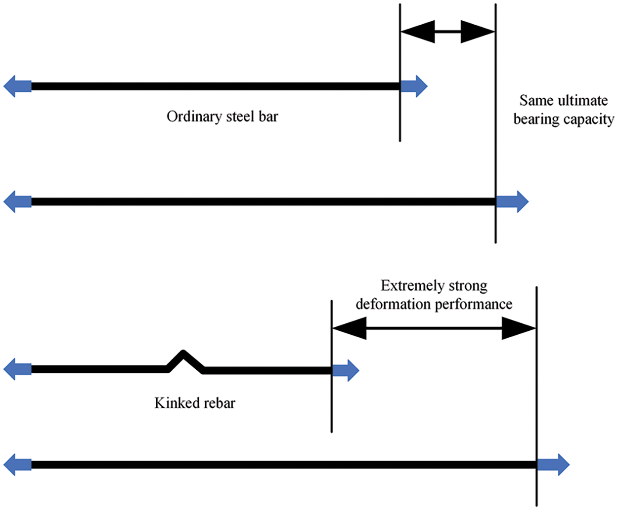
Figure 1: Comparison between kinked rebar and ordinary steel bar
During the loading process, kinked rebar exhibits excellent deformation capabilities, and its ultimate bearing capacity does not decrease. By incorporating kinked rebar in beam-column joints, plastic hinge zones in the beam can be increased, enhancing the beam’s deformation energy absorption capacity. This significantly improves the load resistance of RC beams. Fig. 2 shows the diagram of steel mesh reinforcement applied with kinked rebars. Qiang et al. have found that incorporating kinked rebar in frame structures can simultaneously enhance the seismic resistance and resistance to the continuous collapse of reinforced concrete (RC) frame structures.
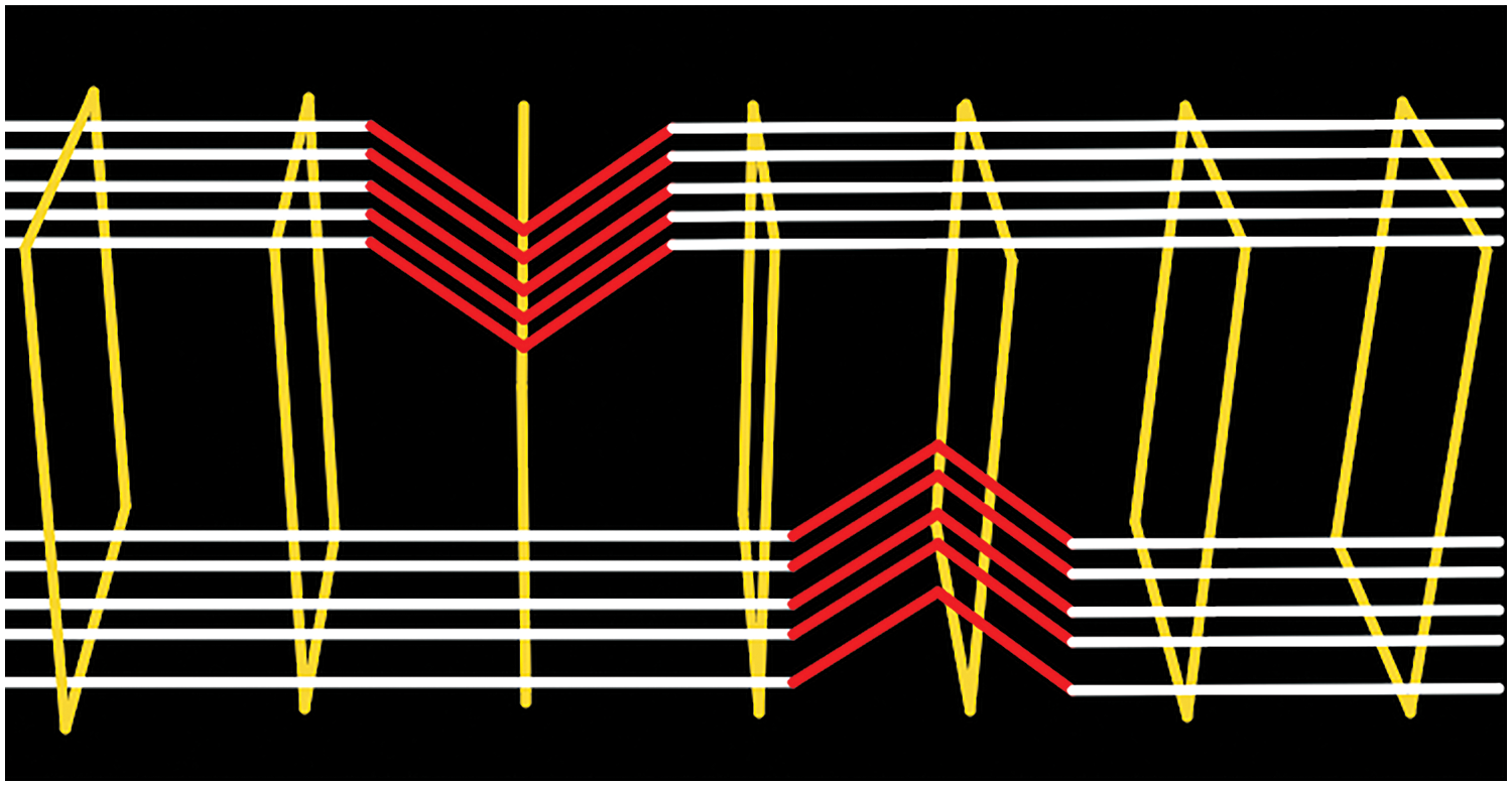
Figure 2: Diagram of steel mesh reinforcement applied with kinked rebars
Based on economy and construction convenience, our research group proposes a new type of reinforced concrete bridge pier with kinked rebars for the transfer of plastic hinges. This further solves the problems of insufficient deformation and energy dissipation capacity in the plastic hinge area of reinforced concrete bridge piers, as well as uneven distribution of concrete damage and difficulty in post earthquake repair.
2 Working Mechanic of Kinked Rebar
Based on the research conducted by Feng et al. [1], numerous experiments [4–6] have been carried out on kinked rebars [7,8], confirming the mechanical properties of kinked rebars under various conditions [9–11], including rebar strength, kinking angle, and rebar diameter [12–14], as shown in Fig. 3. The stress-strain mechanism can be divided into three stages:
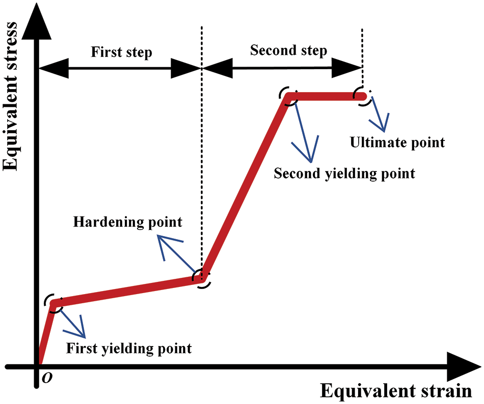
Figure 3: Diagram of stress-strain curves of kinked rebars
a. Elastic stage: During this stage, as the tension increases, the strain of the rebar sections linearly changes with stress. However, due to the presence of residual stress from rebar bending, kinked rebar doesn’t exhibit higher elastic tensile capacity.
b. Platform stage: As tension increases, plastic deformation initiates at the bend of the rebar. Subsequently, the arch-shaped part gradually straightens, and rebar deformation accelerates.
c. Strengthening stage: At this stage, the kinked rebar is fully straightened, and the stress mechanism resembles that of ordinary rebar until failure occurs.
The uniaxial tension process of kinked rebar can be divided into four key points: 1. The first yielding point indicates the gradual straightening of the kinked rebar. 2. The strengthening point indicates a rapid increase in stress. 3. The second yielding point signifies complete straightening and yielding throughout the kinked section. 4. The ultimate point represents the failure or fracture of the kinked rebar [4].
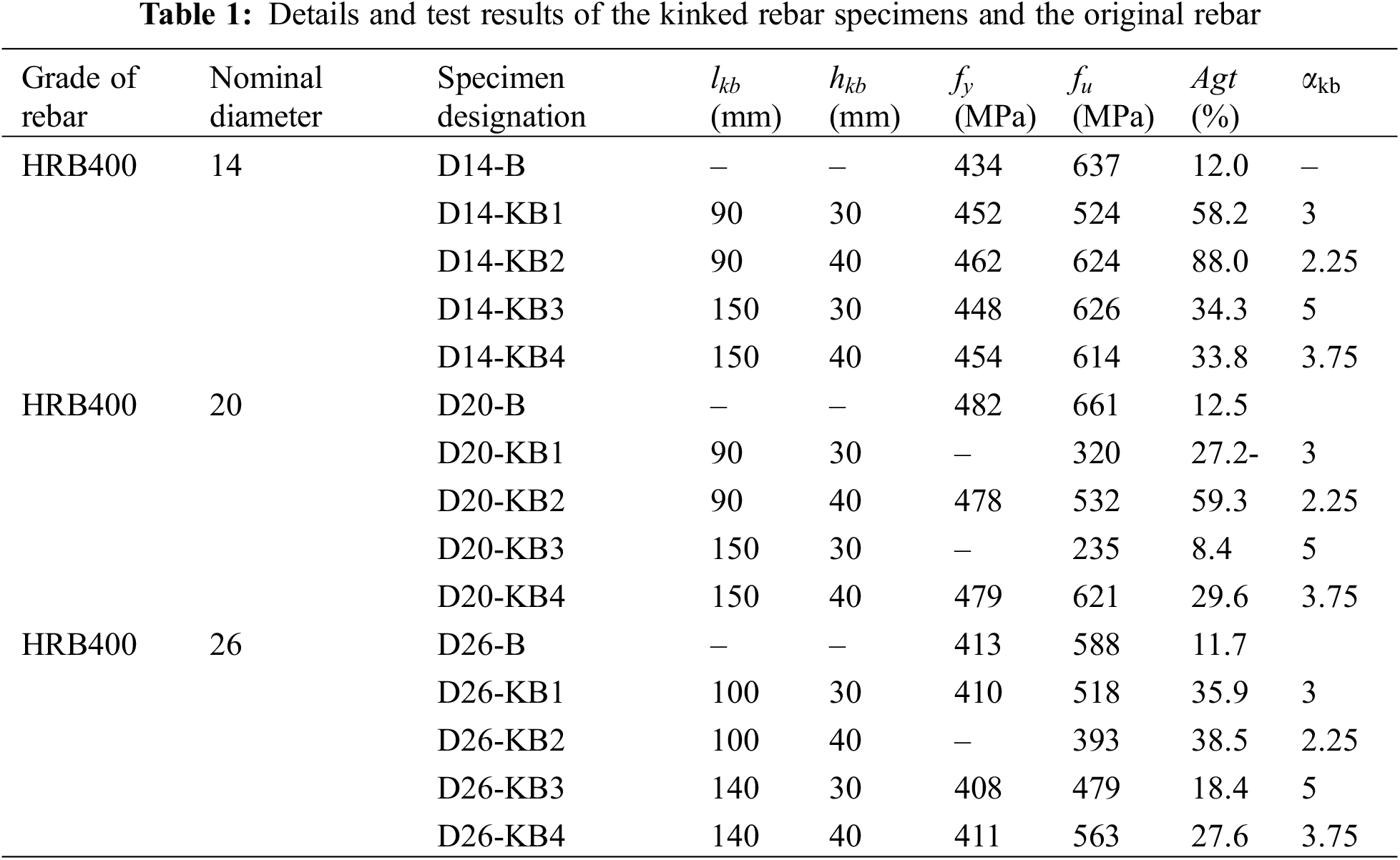
Compared to straight rebar, kinked rebar has a smaller initial strength, the same or higher ultimate strength, and greater tensile deformation capacity, as depicted in Table 1. The higher ultimate strength of some specimens compared to the base material is due to cold work hardening of the kinked rebar. The geometric dimensions of the kink significantly affect its deformation capacity, generally speaking, the larger the geometric dimensions, the greater the deformation capacity, and the lower the stiffness and bearing capacity corresponding to the first yield point on the tensile curve.
3 Current Situation of Research
Based on the working principle of kinked rebar, scholars both domestically and internationally have conducted extensive research, promoting the development and application of kinked rebar in the field of civil engineering structures. Currently, research on kinked rebar can be categorized into three main areas: studies on the tensile mechanical properties of kinked rebar, research on the anti-explosion and anti-seismic performance of kinked rebar-reinforced beam-column nodes, and research on the seismic resistance, anti-explosion, and anti-continuous collapse performance of kinked rebar concrete frame structures. This section will summarize the development process of kinked rebar research in chronological order.
Concept of kinked rebar was first proposed by Feng et al. [1] in 2018. The aim was to enhance the deformation capacity of reinforced concrete frames (RC frames) under seismic loads and to increase the bond strength between components, along with the rotational deformation capacity of collapse sections. Fig. 4 shows the failure modes of RC frame structures and a general view of the column-hinge failure of an RC frame in the 2008 Wenchuan Earthquake.
Figure 4: Failure modes of RC frame structures and a general view of the column-hinge failure of an RC frame in the 2008 Wenchuan earthquake. Reprinted from Reference [1]
In 2019, Fan et al. [2] further investigated the anti-explosion performance of kinked rebar RC beams and used finite element software to simulate the entire process of kinked rebar RC beam failure under load.
In 2020, Qiang [3] conducted cyclic tensile tests and numerical simulations on kinked rebar, presenting a constitutive model for the equivalent stress-equivalent strain relationship in uniaxial tension-compression of kinked rebar. Subsequently, low-cycle reciprocal loading tests were performed on RC beams and RC frames reinforced with kinked rebar. To address the issue of low tension in the elastic stage of kinked rebar, Cai et al. [4] introduced an improved type of kinked rebar with weak connections in 2020. This innovation involved welding a section of weak kinked rebar straight below or to the side of the kinked section of the rebar.
In 2021, Chen et al. [5] expanded the application of kinked rebar to the anti-explosion field of RC structures and proposed a simulation loading test method using a specially shaped bar-shaped airbag for hammer impact (Fig. 5). The study revealed the mechanism of kinked rebar beam resistance to explosions and established a theoretical calculation model for the resistance of kinked rebar concrete beams under explosion loads. Additionally, a formula for calculating the coefficient of resistance dynamics was introduced, providing valuable insights for the widespread implementation of kinked rebar in anti-explosion structures.
Figure 5: Schematic diagram of the test device. Adapted from Reference [5]
In 2022, Qin et al. [6] designed a novel precast beam-column joint featuring embedded kinked rebars, as depicted in Fig. 6. The design of kinked rebars successfully facilitated the transfer of plastic hinges, resulting in improved energy dissipation and deformation capacity.
Figure 6: Details of kinked rebar. Adapted from Reference [6]
In 2022, Liu et al. [7] conducted research on the high-speed dynamic tensile mechanical properties of kinked rebar, introducing the concept of the equivalent tensile strain rate for kinked rebar. They further developed a dynamic increase factors (DIF) model for the elastic ultimate strength of kinked rebar based on this concept, providing a theoretical basis for engineering applications.
In 2023, Yin et al. [8] analyzed the anti-internal explosion performance of 1/8 scaled kinked rebar-reinforced frame structures, as illustrated in Fig. 7. The results indicated that under explosive loads, kinked rebar-reinforced beams effectively prevented the structure from experiencing continuous collapse.
Figure 7: 1/8 scale model. Adapted from Reference [8]
3.1 Tensile Mechanical Properties of Kinked Rebar
As a novel form of steel reinforcement, understanding the tensile mechanical properties of kinked rebar is crucial. Liu et al. [7] conducted experiments and theoretical research on the high-speed dynamic tensile mechanical properties of kinked rebar. They introduced the concept of equivalent tensile strain rate for kinked rebar, treating the entire kinked rebar as an equivalent material. The forces at the bending position are illustrated in Fig. 8, after the kinked rebar end moves outward along the axial direction.
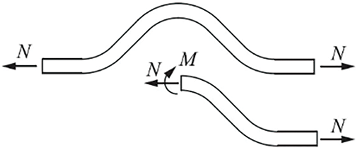
Figure 8: Forces at the bending position. Reprinted from Reference [7]
The average strain rate of the section at the bending position of the rebar kink is defined as the equivalent strain rate of the kinked rebar. Liu et al. [7] elucidated the tensile deformation mechanism of kinked rebar and established the relationship between the equivalent strain rate of kinked rebar and the strain rate of straight rebar. Based on this, the influence of the kinked height of the rebar on the dynamic tensile properties of kinked rebar was studied, and a dynamic increase factor (DIF) calculation model for the elastic ultimate strength of kinked rebar under the influence of kinked height was established, providing a theoretical basis for engineering applications.
In addition, Cai et al. [4] and Mao et al. [9] addressed the issue of low tension in the elastic stage of kinked rebar by proposing an improved type of kinked rebar with weak connections. This involves welding a section of weak kinked rebar straight below or to the side of the kinked section, as depicted in Fig. 9a. Through experiments and finite element simulations, they verified the mechanical performance of this new structure. The comparison curve of equivalent stress-equivalent strain indicates that during the elastic stage, the weak connection section bears the main tension until it fractures. Only after this fracture, as illustrated in Fig. 9b, does the kinked rebar exhibit its performance. Fig. 10 shows the comparison curve of equivalent stress-equivalent strain. This method effectively improves the mechanical performance of kinked rebar in the elastic stage.
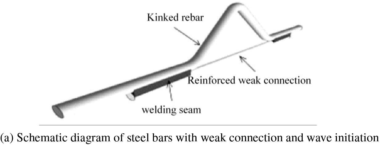
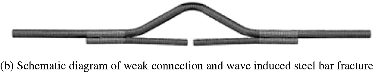
Figure 9: Working principle of kinked rebars with weak connection. Reprinted from Reference [9]
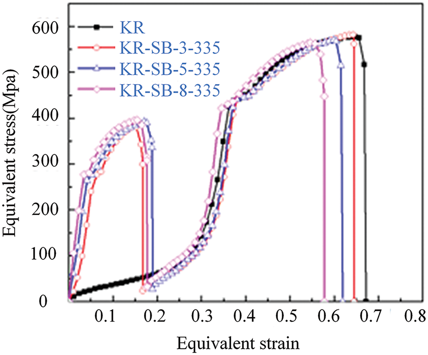
Figure 10: Curve comparison of equivalent stress-equivalent strain. Adapted from Reference [9]
The finite element analysis results of kinked rebar with weak connections reveal that the strength of the weak connection, the length of the weak connection weld, and the position of the weld all impact the tensile mechanical characteristics: 1. Weak connections with lower initial strength offer better ductility but may lead to a slight reduction in the straight section of the kinked rebar. 2. Longer welding lengths result in a stiffer model, reducing the ultimate equivalent tensile strain. 3. Weak connection rebars with lower strength grades cannot fully utilize the strength of the kinked rebar after straightening due to eccentricity effects in side welding, leading to a corresponding decrease in ultimate strain. However, increasing the welding length mitigates the eccentricity effect.
3.2 Kinked Rebar Beam-Column Joint
In the seismic field, various measures have been developed to improve the mechanism of plastic hinge formation [11–13]. However, research aimed at enhancing structural seismic performance by increasing allowable deformation and ductility remains relatively insufficient [6]. Initially applied at the bottom of concrete beams, kinked rebar facilitates the transfer of plastic hinges, ensuring beams fail before columns during earthquakes [14,15]. Moreover, kinked rebar demonstrates robust deformation capabilities during loading processes [16,17].
Qin et al. [6] proposed a novel prefabricated assembly beam-column joint, with dimensions and reinforcement configurations depicted in Fig. 11. Kinked rebar replaces longitudinal reinforcement in the beam-end plastic hinge zone, and its seismic performance compared with conventional joints was explored. The research results, as illustrated in Fig. 12, indicate that specimens with kinked rebar exhibit significantly larger hysteresis loop areas, successfully transferring the plastic hinge zone. Additionally, it is recommended to incorporate additional shear reinforcement in the kinked rebar section to delay or alter undesirable flexural-shear failure and enhance load-carrying capacity. Kinked rebar should also be considered with symmetric arrangements or placed only on one side of the top and bottom.
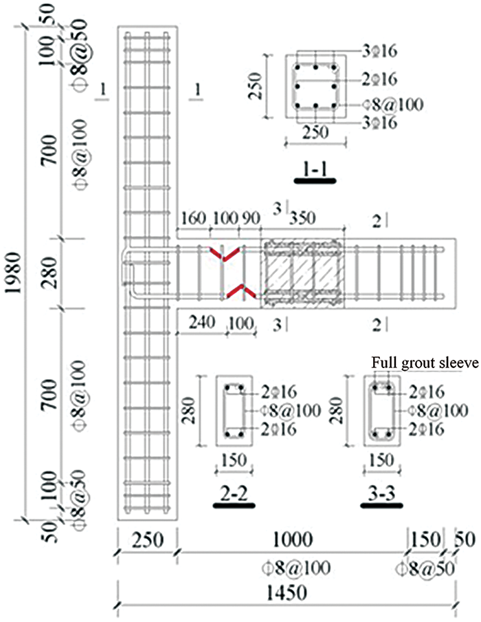
Figure 11: Dimension and details of reinforcements for specimens
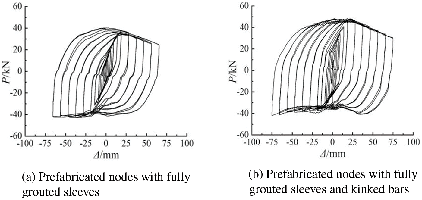
Figure 12: Hysteresis curves of each specimen. Adapted from Reference [6]
Kinked rebar not only effectively enhances the seismic performance of structures but also improves the structural resistance under strong dynamic loads [6]. Chen et al. [2] integrated kinked rebar with structural blast resistance, revealing the mechanism of kinked rebar beam resistance to explosions. The finite element software was employed to simulate the entire process of kinked rebar RC beam failure under load. The results indicate that the proper incorporation of kinked rebar into ordinary RC beams allows for the full utilization of the deformation capacity of kinked rebar under explosive loads, effectively dissipating the impact energy. This verifies the significant advantage of kinked rebar in resisting impact loads.
According to experimental analysis, when constructing the DIF calculation model for the elastic ultimate strength of kinked rebars, it is necessary to consider the combined effects of equal strain rate and static elastic ultimate strength on DIF. These two factors are also related to the wave initiation height, so a fitting relationship can be established between variables a and b in the DIF calculation model and the wave initiation height, thus reflecting the combined influence of the equivalent strain rate and static elastic ultimate strength on DIF.
Based on previous relevant experimental results, a theoretical calculation model for the resistance of kinked rebar beams under explosive impact loads was established to provide a reference for the widespread application of kinked rebar in blast-resistant structures:
In summary, if the specific values of the wave initiation vector height and equivalent engineering strain rate are known, the DIF value of the elastic ultimate strength of the kinked rebar can be obtained from Eq. (3), and the ultimate strength of the elastic segment can be determined.
However, the research findings are only obtained from numerical simulations and theoretical derivations. The blast resistance mechanism and effects of KRC (Reinforced concrete structure with kinked rebars) beams have not been confirmed by prototype dynamic load tests. Therefore, Chen et al. further conducted drop hammer impact airbag loading tests [5]. The research results indicate that kinked rebar reinforcement can increase the number of beam plastic hinges, as shown in Fig. 13. Moreover, it can enhance the beam’s deformation energy absorption capacity and its ability to resist strong dynamic loads such as blast impact on RC beams.
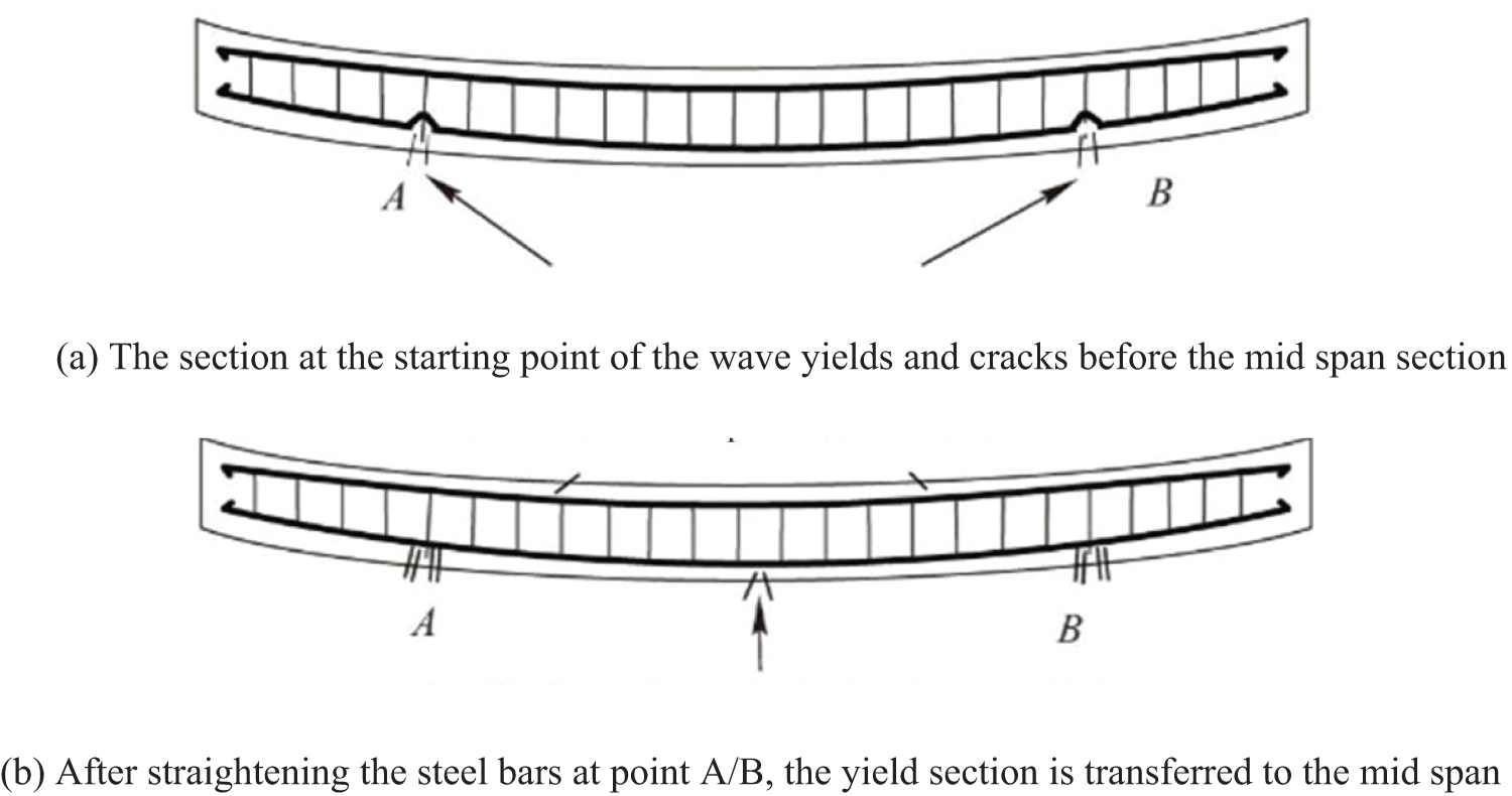
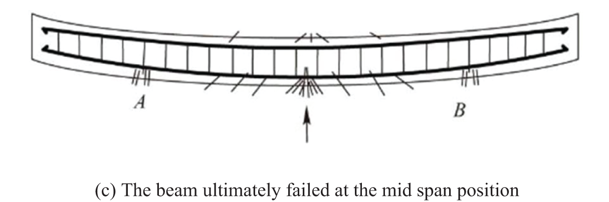
Figure 13: Failure process of KRC beam under external loading. Adapted from Reference [5]
As shown in Fig. 14, under the same maximum deformation conditions, the resistance of properly designed KRC beams (D2-1) is approximately 86.7% higher compared to conventional reinforced concrete (RC) beams. This demonstrates that kinked rebar significantly enhances the resistance performance of beam-column joints.
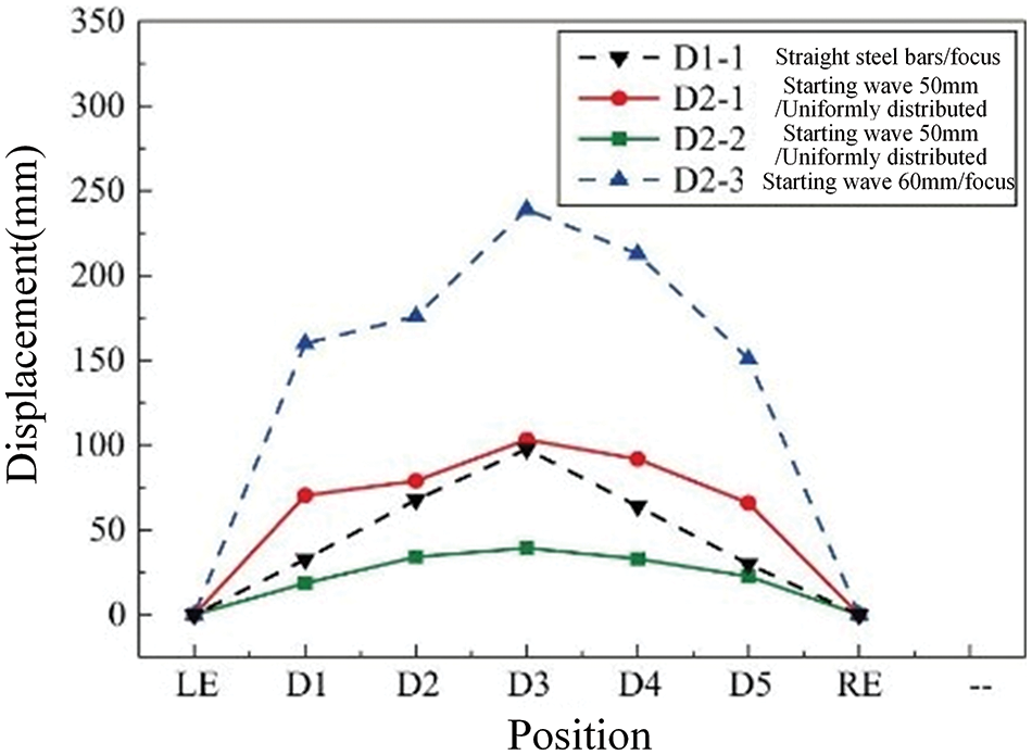
Figure 14: Maximum deformation of the beam specimen. Adapted from Reference [5]
Cai et al. applied kinked rebar with weak connections to RC beams, conducted relevant experiments and simulations, and verified the mechanical performance of the structure under small seismic conditions to ensure that the building remains intact and standing. This provides a theoretical basis for the engineering application of kinked rebar.
3.3 Reinforced Concrete Frame with Kinked Rebar
The contradiction arises in reinforced concrete (RC) frame structures between the demand for reinforcement in anti-continuous collapse design and seismic design principles, which emphasize the concept of “strong columns and weak beams”. Therefore, Feng et al. [1] outfitted frame structures with a novel kinked rebar possessing substantial deformation capacity.
Based on kinked rebar-reinforced frame structures, uniaxial tensile tests, three-point bending tests, four-point bending tests, as shown in Fig. 15, and numerical simulations based on fiber beam models were conducted to study the equivalent stress-strain relationship and deformation modes of kinked rebar, failure modes of beams reinforced with kinked rebar, and the seismic and anti-continuous collapse performance of six-story frame structures with kinked rebar reinforcement. The research findings demonstrate that kinked rebar can effectively meet the seismic requirement of “strong columns and weak beams” (WB-SC), as shown in Fig. 16. “SB-WC” means “strong beams and weak columns”. “SB-WC+KB” means “strong beams and weak columns with kinked rebars.”
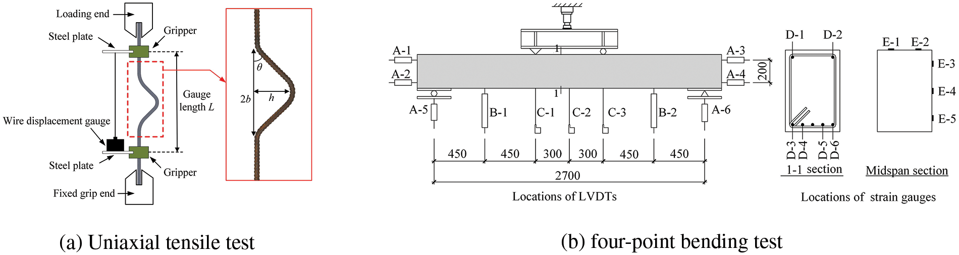
Figure 15: Schematic diagram of the test. Reprinted from Reference [1]
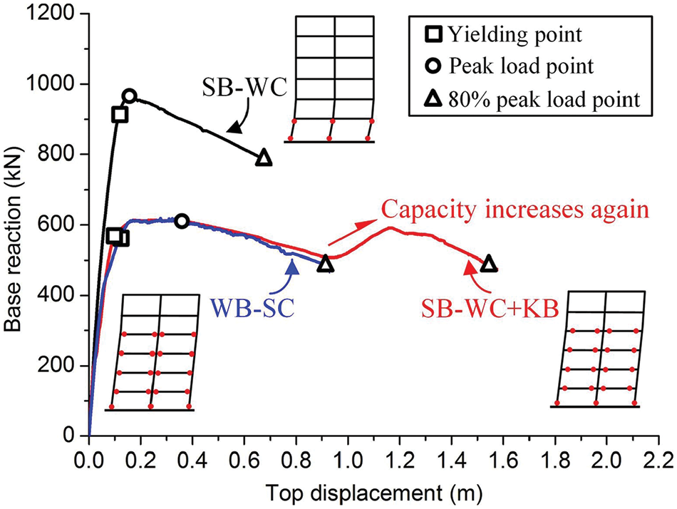
Figure 16: Base reaction and top displacement relation curves. Reprinted from Reference [16]
In addition, the frame structure equipped with kinked rebar achieves plastic hinge redistribution, as shown in Fig. 17, effectively enhancing the continuous collapse resistance of reinforced concrete frames.

Figure 17: Plastic hinge distribution. Reprinted from Reference [1]
Feng et al. further studied the continuous collapse resistance performance of frame structures equipped with kinked rebar under the failure mode of the middle column, as shown in Fig. 18 [11]. The development laws of steel strain and concrete strain in key sections and critical regions of each specimen were also discussed, revealing typical failure phenomena during the continuous collapse process of the specimens.
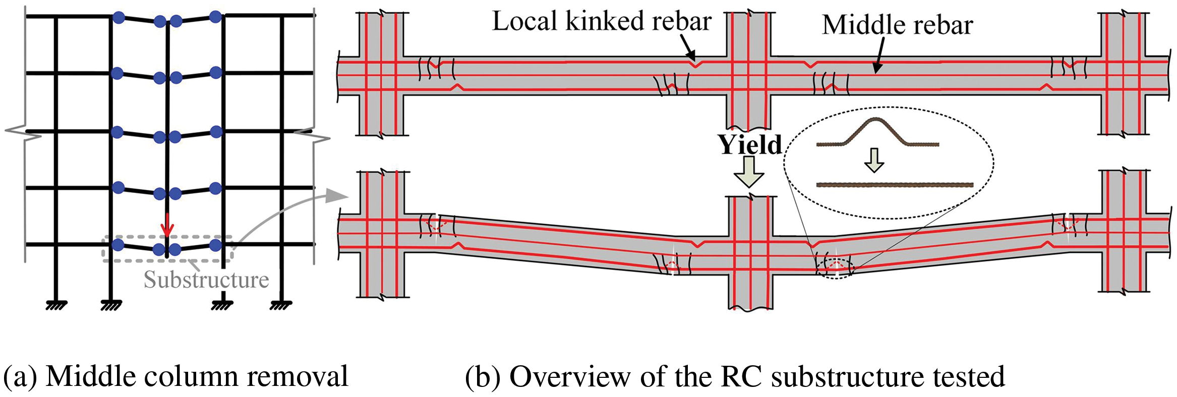
Figure 18: Overview of the RC substructure tested. Reprinted from Reference [11]
Based on the existing calculation methods for the load-bearing capacity of ordinary RC frame structures, a theoretical model for calculating the load-bearing capacity of the substructure suspension chain line with kinked rebar configuration was proposed (as shown in Fig. 19).
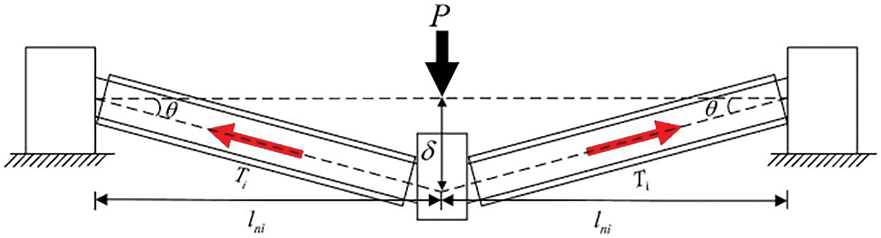
Figure 19: Schematic diagram of the force of the catenary mechanism. Reprinted from Reference [18]
Research results indicate that frame structures equipped with kinked rebar have lower bearing capacity under the arching mechanism but higher load-bearing capacity and greater deformation capacity under the suspension chain line mechanism, as shown in Fig. 20.
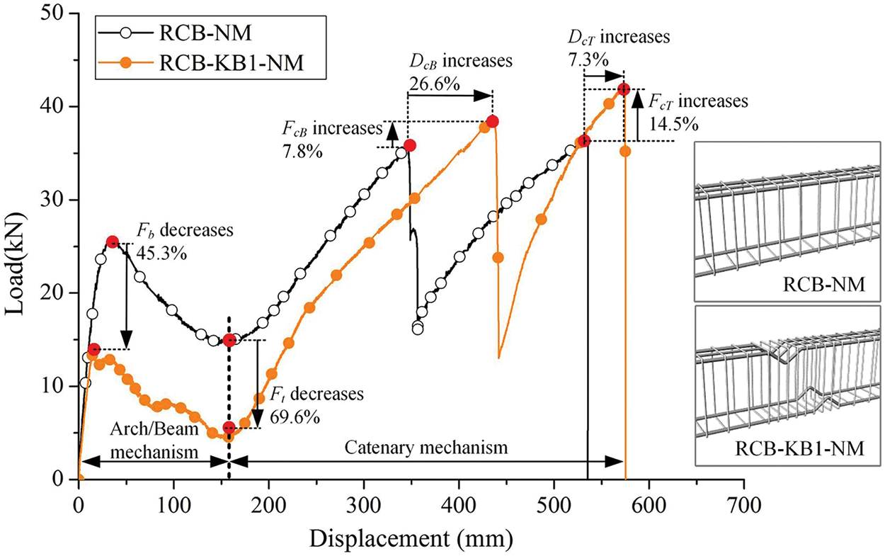
Figure 20: Comparisons of the load-displacement curves of the normal substructure and the substructure with KBs. Reprinted from Reference [16]
Qiao et al. [18] introduced a new principle involving the Reduced Web Section (RWS) connecting the second path, as illustrated in Fig. 21. This approach creates openings in the web of the beam to enhance rotational capacity and involves the installation of kinked rebar in the beam-column joint. Kinked rebars were installed on the inner surface of the beam without compromising the smoothness of the beam surface, thereby reducing the net height of indoor space. Additionally, since the rebars cannot be directly welded to the beam and column, stiffening plates with pre-drilled holes are placed on the beam, with the rebars installed in the pre-drilled holes and anchored to the column and stiffening plate. Both the upper and lower flanges of the beam end should be reinforced with kinked rebar.
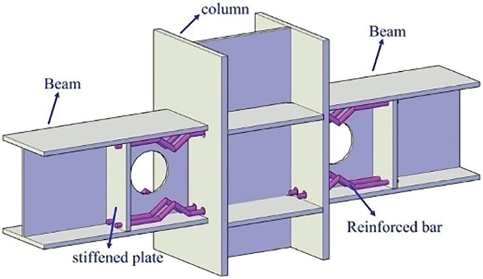
Figure 21: Reinforced RWS connections. Reprinted from Reference [18]
To investigate the enhancement of continuous collapse resistance in frame structures with open beam webs through the use of kinked rebar, Qiao et al. [18] conducted experiments and numerical simulations on the lower portion of frame structures equipped with kinked rebar configuration. The study evaluated the deformation capacity of the rebar, vertical force, deformation response, failure modes, and the contribution of bending and suspension chain line effects to the rebar. Results indicate that the kinked rebar becomes active after reaching the plastic state and plays a crucial role in the catenary effect. Moreover, experimental findings suggested appropriate ranges for configuring the height of kinked rebar, emphasizing that the rebar’s height should be chosen based on the beam’s deformation capacity, with the rebar diameter ideally half of the kinked diameter.
In addition to superior seismic performance, frame structures equipped with kinked rebar configuration also demonstrate excellent blast resistance. Yin et al. employed a simplified hybrid finite element method to construct full-scale frame models and conducted comparative analyses on the blast resistance performance of frame structures with different kinked rebar configurations (as depicted in Fig. 22) [8]. The results indicate that, when considering energy dissipation and load-bearing capacity comprehensively, positioning kinked rebar at one-third of the beam end outperforms placing it at the midspan under internal blast effects. Kinked rebar-reinforced beams effectively absorb explosive impact forces, reduce support reactions, delay the appearance of peak support reactions, protect frame columns, and effectively prevent the main vertical load-bearing components of frame structures from failing under local internal blast effects, thereby averting localized collapse of the structure.
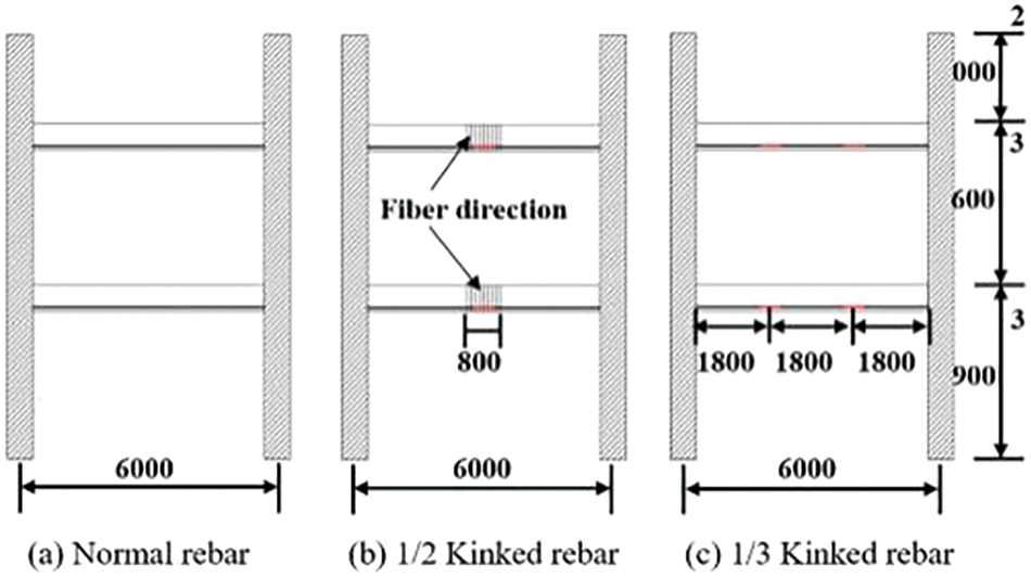
Figure 22: Equivalent kinked rebar location (Unit: mm). Reprinted from Reference [8]
Qiang [3] conducted reciprocating tensile tests and related numerical simulations on kinked reinforcement bars, proposing a constitutive model of the equivalent stress-strain relationship for uniaxial tension-compression of kinked reinforcement bars. Additionally, considering factors such as the shape of kinked reinforcement bars, kinking angle, and spacing of stirrups, low-cycle reciprocating loading tests were performed on RC beams and RC frames reinforced with kinked rebars. By combining relevant finite element simulation results with theoretical analysis, they proposed a plastic hinge hysteretic rule for kinked reinforcement bars. Subsequently, they established a theoretical hysteresis model of moment-rotation for kinked reinforcement bar beams, illustrated in Fig. 23.
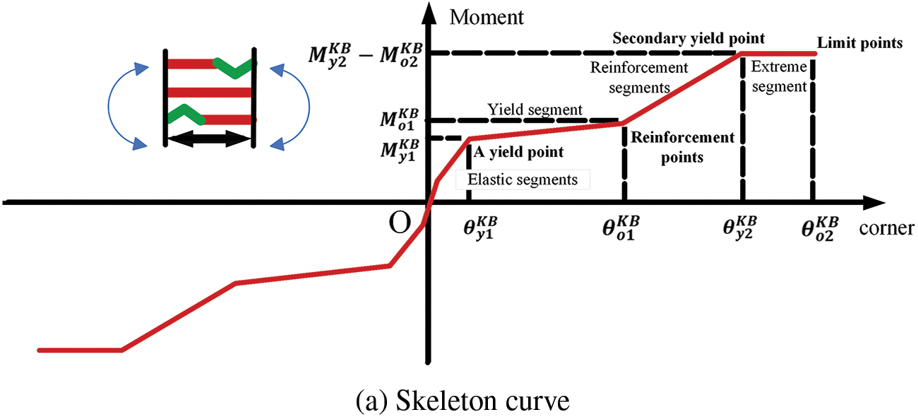
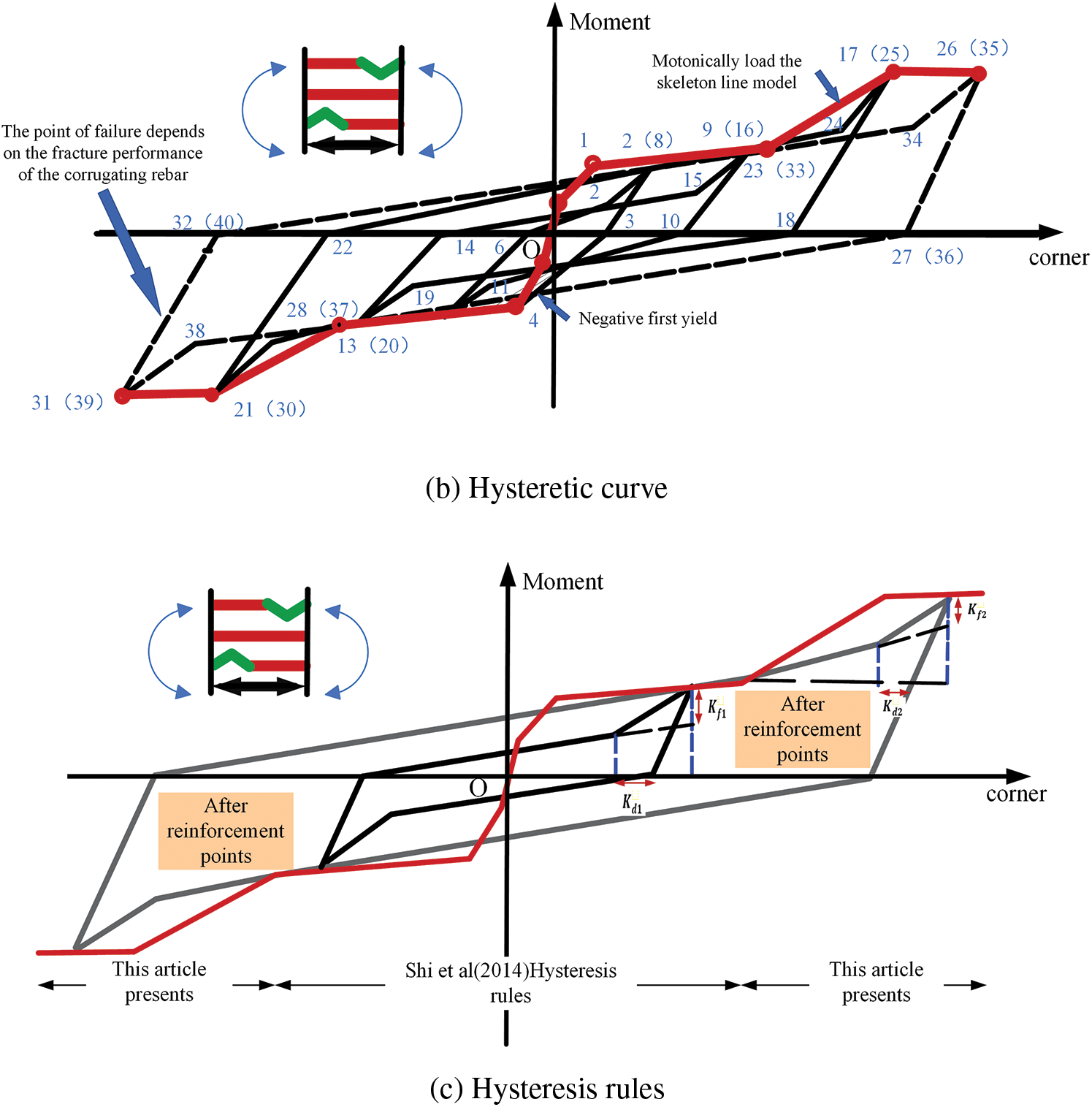
Figure 23: A plastic hinge moment rotation hysteresis model for kinked rebar. Adapted from Reference [3]
Furthermore, the research results indicate that the plastic hinges of the frame substructures with kinked rebar configuration appear at the location of the kinked rebar on the beam and at the bottom of the column, showing a “strong column weak beam” failure mode. Moreover, the improvement effect of configuring beams with kinked rebar in multi-story frame structures is more significant, exhibiting greater lateral deformation capacity compared to ordinary frames, as shown in Fig. 24, further validating the significant advantage of the strong deformation performance of kinked rebar under seismic loading.
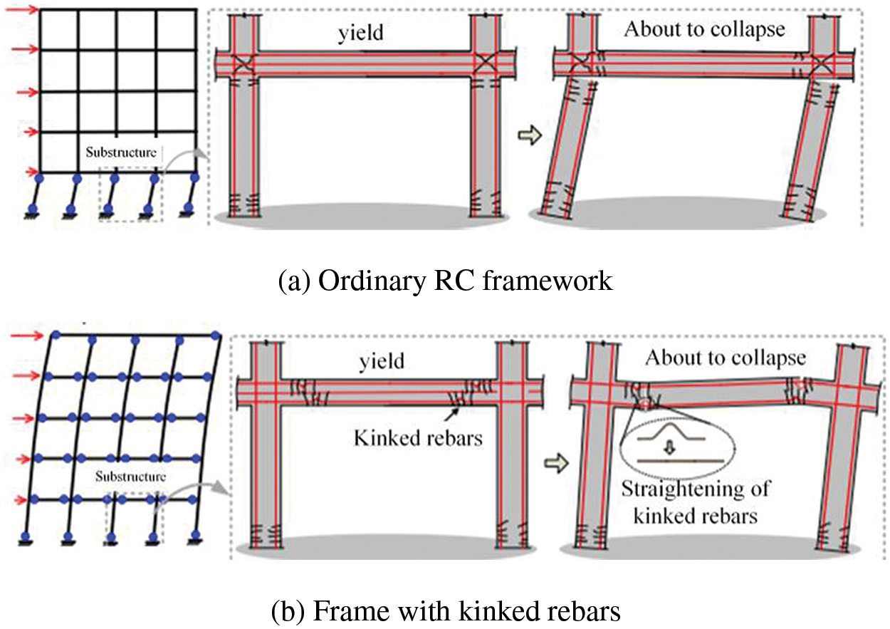
Figure 24: Schematic diagram of lateral deformation mechanism of RC frame structure. Adapted from Reference [3]
Xiao et al. [19] conducted vibration table tests to evaluate the seismic performance of a 4-story novel reinforced concrete frame structure at a 1/4 scale. The proposed frame structure includes beams with kinked rebar as longitudinal reinforcement and columns reinforced with Carbon Fiber Reinforced Polymer (CFRP) bars to achieve post-yield hardening [12]. The research results indicate that compared to traditional frames, this frame effectively reduces inter-story drift and residual drift ratio, demonstrating better seismic performance and self-centering capabilities. The novel frame structure successfully achieves a “strong column weak beam” failure mode [20–22], as shown in Fig. 25, and effectively enhances reparability.
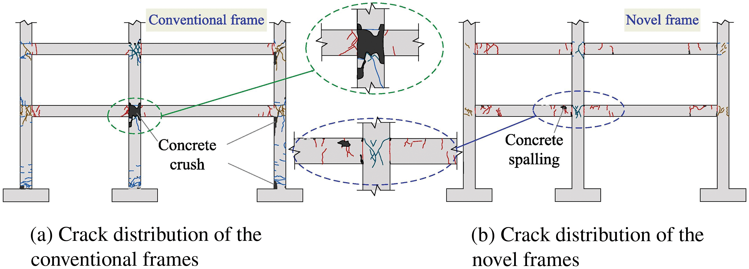
Figure 25: Comparison of crack distribution of the conventional and novel frames under strong seismic intensities in y direction. Reprinted from Reference [19]
Furthermore, building upon previous research findings, it was discovered that the short elastic segment of kinked rebar might not meet the requirements of normal serviceability limit states and “no damage under minor seismic events”. Moreover, under moderate seismic events, kinked rebar sections could experience significant damage, leading to substantial vertical deflection in beams and posing challenges for later repairs. Therefore, addressing these imperfections, Cai et al. applied kinked rebars with weak connections to frame structures and conducted relevant experiments and finite element simulations. The experimental results indicate that this design effectively enhances the initial elastic segment of kinked rebar, meeting the requirements of “no damage under minor seismic events” and normal serviceability limit states. Additionally, the constraint effect of the weak connection on the kinked rebar increases its stress level during straightening, slowing down the straightening process, thus meeting the requirement of “repairable under moderate seismic events”.
4 The Prospects/Outlook for Other Applications of Kinked Materials
1. The novel kinked rebar has demonstrated significant effectiveness in various domains, including seismic resistance [23], resistance to strong dynamic loads [24–26], and resistance to progressive collapse [27,28]. The concept of “kinked rebar” can be integrated into diverse structural systems such as steel plate shear walls [29,30], corrugated steel tube concrete columns [31,32], reinforced frames with corrugated steel plates [33–36], and origami-type engineering impact-resistant metamaterials [37–40]. These structures share a common principle with kinked rebar—they enhance structural deformability by bending to a certain angle, thereby improving the seismic resistance, resistance to progressive collapse, or impact resistance of the structure.
(a) Corrugated steel plates possess excellent deformability, seismic performance, and resistance to collapse.
I. Under seismic forces, the confinement effect of rectangular steel tubes on concrete weakens, and the steel’s strength remains underutilized. To leverage the significant out-of-plane stiffness of corrugated steel plates and enhance the confinement performance of steel tubes on core concrete, Li [31] introduced a novel concept: concrete filled rectangular corrugated steel tubular column formed by welding parallel opposing flat steel plates and corrugated steel plates, as shown in Fig. 26. Through numerical simulation, the seismic performance and compressive bending capacity of this innovative column design were analyzed. The findings suggest that the Novel concrete filled rectangular corrugated steel tubular column exhibits outstanding seismic resilience. The corrugated plates, owing to their remarkable out-of-plane stiffness, effectively confine the core concrete, serving as both flanges and web plates. The optimal confinement effect is observed at the corrugation peaks, highlighting the efficacy of this novel structural configuration.
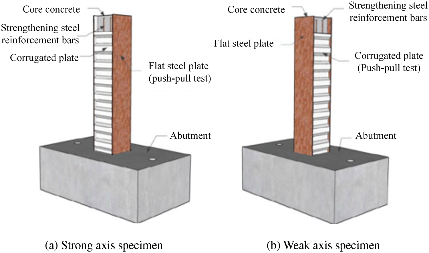
Figure 26: Novel concrete filled rectangular corrugated steel tubular columns. Adapted from Reference [31]
II. Li et al. [29] proposed a trapezoidal corrugated steel plate shear wall, as shown in Fig. 27. This structure exhibits high elastic-plastic buckling load and large ductile deformation capacity. Through experimental research on wall panel parameters and numerical simulations, it was verified that the corrugated steel plate shear wall specimens have excellent hysteresis characteristics. Increasing the width-to-thickness ratio of the wall panel can significantly improve the flexural displacement angle and bearing capacity, while increasing the out-of-plane wave folding angle can enhance the flexural displacement angle and bearing capacity. The width-to-height ratio of the wall panel should not be too large.
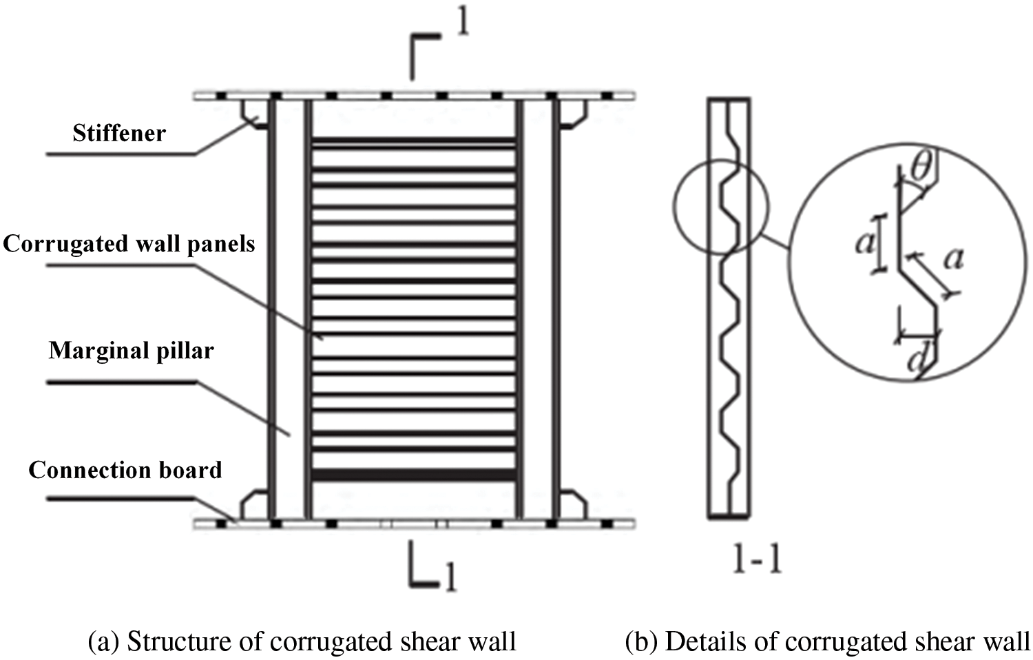
Figure 27: Structure of corrugated shear wall. Adapted from Reference [29]
III. In order to enhance the anti-collapse capability of steel frame structures, Meng et al. [33] conducted comparative experiments on different types of strengthening plates and proposed a novel weakened beam-column flange plate connection with “V” shaped reinforcement plates added to the weakened sections on the upper and lower flanges of the beam (RBS connection), as shown in Fig. 28.
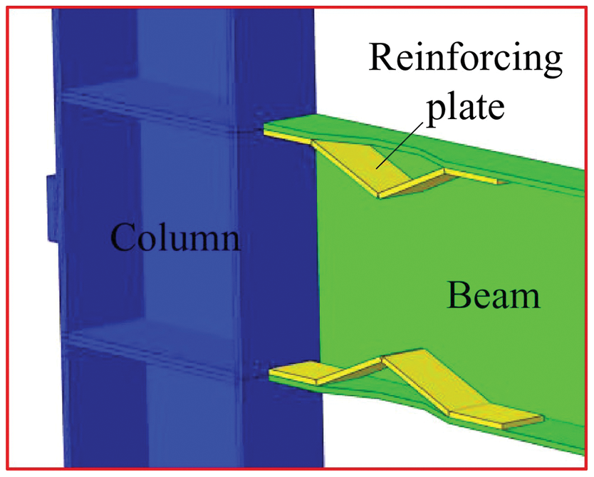
Figure 28: RBS connection with reinforcing plate. Reprinted from Reference [33]
The research results indicate that increasing the “V” shaped reinforcement plates effectively enhances the load-bearing capacity and corresponding displacement of the sub-components when the catenary line action in the beam is fully exerted. Adding “V” shaped reinforcement plates slightly improves the seismic performance of the RBS connection. When a planar steel frame adopts “V” shaped reinforcement plates, especially when the bottom central column fails, it can increase the maximum resistance reserve. Furthermore, based on the development process of the load-displacement and internal force-displacement curves of different strengthening plates, it is evident that adding “V” shaped reinforcement plates to components of the RBS connection achieves the best combination of load-bearing capacity and deformation compared to other types of reinforcement plates.
Tian et al. [35] innovatively welded corrugated steel plates between the inner side of the I-beam flange and the column, creating a novel corrugated plate steel frame strengthening node, as depicted in Fig. 29. They conducted collapse resistance tests on the newly reinforced node under welding and bolt welding conditions. Moreover, the study analyzed the influence of the arc length, thickness, and central angle of the corrugated plate on the collapse resistance performance of the reinforced node. The research findings indicate that the specimens primarily failed due to the fracture of the outer beam flange in the reinforced area, followed by the sequential fracture of the tension flange and corrugated plate in the node area. Importantly, the bearing capacity and ductility of the reinforced specimens saw significant improvement, with the corrugated plate offering additional resistance reserve for the steel frame structure.
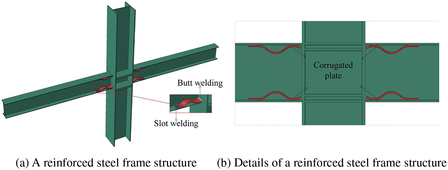
Figure 29: Schematic of a reinforced steel frame structure. Reprinted from Reference [35]
Furthermore, a comparative study was conducted on the influence of partial penetration welding or full penetration welding between the corrugated steel plate and the column on the collapse resistance performance of the structure [36]. Finite element model of specimen collapse resistance of the welding form (CRWF) is shown in Fig. 30. The results indicate that the two welding methods have nearly the same collapse resistance capability for the lower structure. Although the latter provides more safety reserves for the lower structure, its construction is more complex. In contrast, the former has a simpler structure, hence it is more practical.
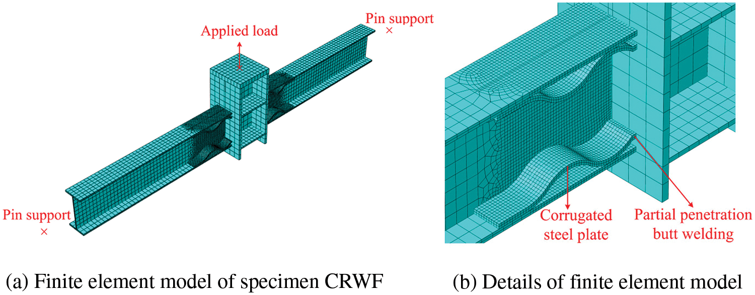
Figure 30: Finite element model of specimen CRWF. Reprinted from Reference [36]
To enhance the continuous collapse resistance of frame structures, Wei et al. [34] proposed an innovative principle for improving frame structures—partial plastic zone outward movement. Utilizing this principle, they developed an improved steel frame structure using corrugated steel plates, as shown in Fig. 31. By employing corrugated plates with appropriate stiffness, the structure’s resistance to continuous collapse can be effectively enhanced. The feasibility of the partial offset plastic zone principle was validated through the improved frame. Furthermore, this study further optimized the design by incorporating multi-layer steel plates and high-strength steel into the modified frame. The multi-layer structure eliminates composite effects, thereby reducing damage accumulation and enhancing the seismic performance of the structure.
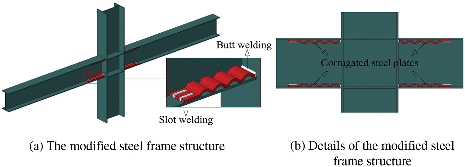
Figure 31: Schematic of the modified steel frame structure. Reprinted from Reference [34]
(b) Origami structures have excellent deformation and impact resistance capabilities.
Cai et al. proposed an improvement principle for structural components based on origami elements, as shown in Fig. 32: By arranging the folds, additional stiffness and novel deformation modes are introduced, guiding the deformation of traditional components and avoiding low-order buckling.

Figure 32: Schematic diagram of the improvement principle of origami elements on structural components
Moreover, based on this principle, various origami-type impact protection materials have been designed: The first type of metamaterial introduces folds into traditional honeycombs and optimizes them by designing folding angles and cell lengths, resulting in origami-type honeycombs with significantly enhanced in-plane strength compared to ordinary honeycombs; The second type of metamaterial introduces folds into negative Poisson’s ratio honeycombs to avoid local buckling, creating negative Poisson’s ratio origami-type honeycombs, which further increase their energy absorption capacity and in-plane strength; The third type of metamaterial optimizes the cross-section of Kresling honeycombs while introducing origami elements to create Kresling origami honeycombs with two-stage energy absorption characteristics, exhibiting multi-peak features during compression.
2. Bridges play a crucial role in road transportation, and bridge piers, as the main load-bearing components [41–43], require thorough investigation of their mechanical performance under seismic conditions [44,45]. The mechanical failure of bridge piers during earthquakes, as shown in Fig. 33, may lead to continuous collapse, causing significant economic losses and inconvenience to daily life. Numerous seismic disasters have shown that the seismic damage to reinforced concrete pier columns is mainly due to the limited energy dissipation and plastic deformation capacity of the plastic hinge region at the base of the pier [46–48], which cannot provide sufficient plastic deformation [49,50]. Moreover, damage occurs in various parts of the pier body and base, making repairs difficult and significantly shortening the normal service life of the bridge [51–53].

Figure 33: Failure of connection of bridge and pier of bridges. Reprinted from Reference [48]
The engineering community has undertaken extensive research to enhance the seismic performance of concrete bridge piers. Scholars have explored various methods to reinforce the plastic hinge region using different confinement materials. Gu et al. reinforced concrete columns with fiber-reinforced polymer (FRP) materials, demonstrating their effectiveness in inhibiting concrete spalling and improving the deformation capacity of plastic hinges. Hosseini et al. [54] utilized cement-based composite (ECC) to create ECC sleeves around longitudinal steel bars, with ordinary concrete poured between the sleeves. Their findings showcased ECC’s superior tensile properties, strong bonding with longitudinal steel bars, and its ability to enhance the energy dissipation capacity and shear bearing capacity of the plastic hinge region.
Farzad et al. [55] repaired damaged zones of reinforced concrete plastic hinges using ultra-high-performance concrete (UHPC) as the repair material, preserving good bearing capacity even as the concrete protective layer gradually peeled off, effectively enhancing energy dissipation and deformation capacity. Han et al. [56] substituted polyvinyl alcohol (PVA) fiber-reinforced concrete for ordinary concrete, observing slow crack development and an effective bridging effect of the fibers during failure under high axial compression ratios, exhibiting a ductile failure mode.
Furthermore, incorporating energy dissipation bars (ED bars) into the plastic hinge region can significantly enhance seismic performance. For instance, Cai [57] utilized energy dissipation bars and self-resetting bars as longitudinal reinforcement, employing ordinary hot-rolled ribbed steel bars for the energy dissipation bars [58] to leverage their elastoplastic characteristics, enhancing the column’s hysteresis energy dissipation capacity. Wang et al. [59] conducted quasi-static tests on large-scale energy dissipation steel bar specimens with various local structures, revealing that increasing the segment height of the plastic hinge region of the pier enhances the column’s hysteresis energy dissipation.
Ou et al. [60,61] investigated the seismic performance of energy dissipation bars through quasi-static tests, finding that they could enhance hysteresis energy dissipation capacity and horizontal bearing capacity, leading to an increase in ultimate displacement. This suggests that configuring energy dissipation bars effectively improves the seismic performance of piers.
The above application of kinked rebar can enhance the seismic performance of reinforced concrete bridge piers. However, different confinement materials are relatively expensive, require high precision in mixing, and entail complex local arrangements of energy dissipation bars. This involves multiple processes and material coordination, demanding higher assembly requirements for workers.
As shown in Fig. 34, the maximum displacement of the main girder of the Yingxiu Minjiang Bridge on the Dujiangyan—Wenchuan Expressway is only 1.8 m. The application of kinked rebar can achieve a better balance between economy and construction convenience. Moreover, the combination of kinked rebar and steel cage also improves the drawbacks of reinforced concrete bridge piers, such as dispersed damage and large residual displacement.
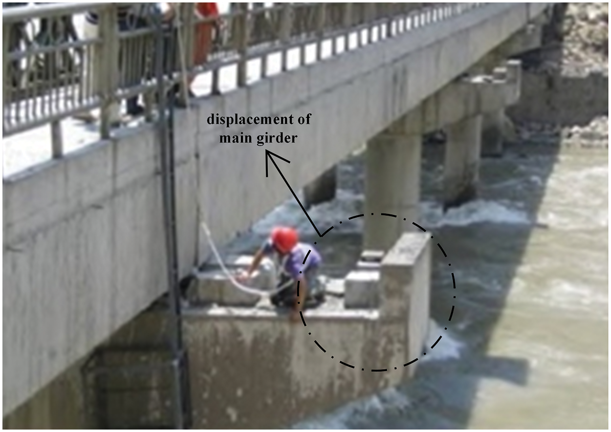
Figure 34: The maximum displacement of bridge in Dujiangyan. Adapted from Reference [48]
To expedite post-earthquake pier repairs, our research team proposes the use of bending-up reinforcement bars in the potential plastic hinge region of the pier columns, as shown in Fig. 35. This enhancement serves to further enhance the seismic performance of reinforced concrete bridge piers.

Figure 35: Schematic diagram of bridge pier with kinked rebars
In order to further address the insufficient deformation and energy dissipation capacity of the plastic hinge zone of reinforced concrete bridge piers, as well as the uneven distribution of concrete damage and the difficulty of post earthquake repair, our research group proposes a new type of reinforced concrete bridge pier with kinked rebars based on economy and construction convenience.
Wang et al. have conducted relevant experiments by subjecting the kinked rebars to uniaxial tensile tests, as shown in Fig. 36, to study the mechanical properties. The test parameters include the diameter d of the bar and the kinked coefficient

Figure 36: Test setup for original rebar and kinked rebar specimens
Three reinforced concrete bridge piers equipped with kinked rebars were modeled using the finite element software ABAQUS: one is a typical reinforced concrete bridge pier (RC-B pier), while the other two incorporate kinked rebars (RC-KB series piers). The parameter variable is the kinked coefficient
When the axial compression ratio is 0.1, all three models are subjected to low-cycle reciprocating loading. The experimental setup is illustrated in Fig. 37. Seismic performance indicators such as hysteresis curves, skeleton curves, residual displacements, and energy dissipation capacity are utilized for measurement.
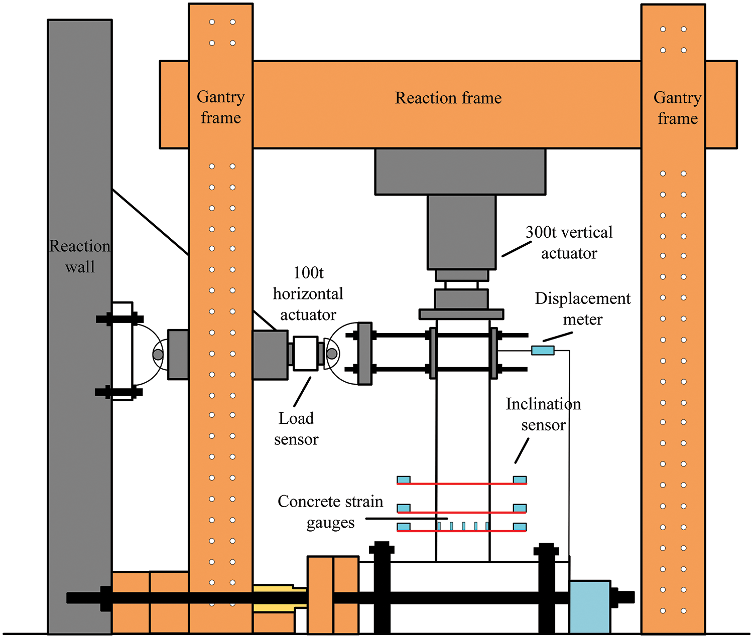
Figure 37: Specimen test setup diagram
The research findings indicate that concrete bridge piers reinforced with kinked rebars can achieve concentrated concrete damage. In this experiment, digital image correlation (DIC) technology was utilized for process recording, as depicted in Fig. 38, a comparison chart of hysteresis curves between reinforced concrete bridge piers with (RC-KB2/4) and without kinked rebars (RC-KB) is illustrated in Fig. 39, It can be intuitively seen that the peak bearing capacity of bridge piers with kinked rebars is smaller than that of ordinary bridge piers, but the stiffness of the bridge pier with kinked rebars decreases slowly in the later stage of loading. The RC-KB series bridge piers can achieve concentrated concrete damage, and the compressive damage distribution height of the RC-KB series bridge piers is smaller than that of the RC-B bridge piers. The damage height of the RC-B bridge pier is 480 mm, while the damage heights of RC-KB2 and RC-KB4 are 280 and 320 mm, respectively, reducing 41.6% and 33.3%, respectively. This can reduce the height of the plastic hinge zone at the bottom of the pier, making it easier for later repair.

Figure 38: Concrete damage and failure of each specimen

Figure 39: Hysteretic curves of specimens
Additionally, there is a certain improvement in ductility and energy dissipation capacity. During the later stages of loading, the bearing capacity gradually increases, exhibiting a clear secondary stiffness phenomenon, thus providing strength assurance for the later stages of loading. Moreover, it is advisable for kinked rebars to be outwardly arranged, positioned at an appropriate distance within the potential plastic hinge zone, with relatively small wave heights.
1) Kinked rebars exhibit remarkable strength retention even after straightening, significantly enhancing the ductility and energy dissipation capacity of structures. In beam-column nodes reinforced with kinked rebars, the successful transfer of plastic hinges achieves the design objective of “strong columns and weak beams.” Moreover, the incorporation of kinked rebars greatly enhances the beam resistance. Consequently, the seismic resilience, blast resistance, and resistance to continuous collapse of reinforced concrete (RC) frame structures with kinked rebar reinforcement are substantially improved.
2) The unique properties of kinked rebars make them a valuable form of reinforcement. Integrating kinked rebars into beam-column joints and frame beams comprehensively enhances the blast resistance, seismic resistance, and resistance to continuous collapse of RC beam-column joints and frame structures, all without significantly increasing costs.
3) Based on the outstanding performance of kinked rebars, the principle of kinking can be extended to explore corrugated steel plates, corrugated steel tubes, and origami structures. These structures rely on bending to enhance deformation capacity, thereby bolstering their seismic resistance, resistance to continuous collapse, or impact resistance.
4) The application of kinked rebars in the bridge domain is proposed to enhance the seismic performance of bridges in later stages. This approach can avoid the problem of concentrated damage, and substantial residual displacement in reinforced concrete bridge piers can be alleviated, enhancing the seismic performance of piers as well as the efficiency of post-earthquake pier repairs.
5) The uniaxial tensile failure process of kinked rebars is different from that of straight steel bars, manifested as first straightening and then breaking. When straight steel bars yield, kinked rebars are still in a lower stress state; To ensure sufficient deformation of the steel bars and reach the ultimate strength of the base material, it is recommended to take the wave initiation coefficient
6) Based on the study of the mechanical properties of kinked rebars, further research on the mechanical properties of kinked rebars wrapped in concrete can be carried out, and a part of the specimen can be tested separately to study the deformation process of kinked rebars in concrete; For section optimization design, a comparison can be made between pre optimization and post optimization specimens to verify whether the deformation and energy dissipation capacity of the bridge pier can be further improved while meeting the bearing capacity requirements.
Acknowledgement: The authors would like to thank Tutor Yifang Huang at the Training Platform of Construction Engineering at the Polytechnic Institute of Zhejiang University for their help in the kinked rebars test.
Funding Statement: This research was supported by the Zhejiang Provincial Natural Science Foundation of China under Grant No. LTGG23E080001 and Zhejiang Engineering Research Center of Intelligent Urban Infrastructure under Grant No. IUI2022-ZD-01.
Author Contributions: The authors confirm contribution to the paper as follows: Conceptualization, Writing—Review and Editing, Project Administration: Chengquan Wang; Writing—Original Draft Preparation: Lei Xu; Supervision: Yun Zou; Investigation: Boyan Ping, Kangyu Wang; Validation: Xinquan Wang; Project Administration: Xiao Li. All authors reviewed the results and approved the final version of the manuscript.
Availability of Data and Materials: The authors confirm that the data supporting the findings of this study are available within the article.
Ethics Approval: Not applicable.
Conflicts of Interest: The authors declare no conflicts of interest to report regarding the present study.
References
1. Feng P, Qiang H, Qin W. Gao M. A novel kinked rebar configuration for simultaneously improving the seismic performance and progressive collapse resistance of RC frame structures. Eng Struct. 2017;147(11):752–67. doi:10.1016/j.engstruct.2017.06.042. [Google Scholar] [CrossRef]
2. Fan Y, Chen L, Ren H, Feng P, Fang Q. Theoretical calculation method for the mechanism of anti explosion effect and resistance dynamic coefficient of RC beams with kinked rebars. Explos Impact. 2019;39(3):123–34. [Google Scholar]
3. Qiang H. Research on seismic performance of a new type of RC frame with reinforced beams with kinked rebars and yield strengthened columns (Ph.D. Thesis). Tsinghua University: China; 2020 (In Chinese). [Google Scholar]
4. Cai X, Mao J, Mao X, Tian S. Study on the tensile mechanical properties of kinked rebars. Eng Seismic Reinforcement Renovat. 2021;43(4):44–51. [Google Scholar]
5. Chen L, Ren H, Fan Y, Zong Z, Liu S. Experimental study on the resistance performance of beams with kinked rebars under strong dynamic loads. J Civil Eng. 2021;54(10):1–8+19 (In Chinese). [Google Scholar]
6. Qin Y, Chen Q, Zhang C, Wang J. Experimental study on seismic performance of precast beam column joints with kinked rebars. J Jilin Univ (Eng Ed). 2023 (In Chinese). [Google Scholar]
7. Liu S, Chen L, Cao M, Zhou D, Fan Y, Chen X. Study on the mechanical properties of high-speed dynamic tensile kinked rebars. Explos Impact. 2022;42(5):26–37 (In Chinese). [Google Scholar]
8. Yin H, Chen B. Numerical simulation of internal explosion resistance of reinforced concrete frame structures with kinked rebars. J High Press Phys. 2023;38(1):014202-1–12 (In Chinese). [Google Scholar]
9. Mao J, Cai X. Finite element analysis of tensile mechanical properties of kinked rebars with weak connection. Jiangsu Arch. 2020;(5):39–42 (In Chinese). [Google Scholar]
10. Mao J. Mechanical performance test and simulation of kinked rebar reinforced beams and frames with weak connections (Master’s Thesis). Suzhou University of Science and Technology: China; 2020. [Google Scholar]
11. Jiang Y, Wei L, Lu J, Lu Z. Exploration of a new scheme of artificial plastic hinge at the beam end of reinforced concrete frame joints. J Southeast Univ. 1991;(1):42–9 (In Chinese). [Google Scholar]
12. Krish ZF, Kowalsky MJ, Nau JM, Seracino R. Repair of reinforced concrete bridge columns via plastic hinge relocation volume 1: repair using conventional materials. In: Final report for the Alaska. Juneau, AK, USA: Department of Transportation & Public Facilities; 2018 Sep 30. [Google Scholar]
13. Yuan W, Guo AX, Li H. Experimental investigation on the cyclic behaviors of corroded coastal bridge piers with transfer of plastic hinge due to non-uniform corrosion. Soil Dyn Earthq Eng. 2017;102:112–23. doi:10.1016/j.soildyn.2017.08.019. [Google Scholar] [CrossRef]
14. Zhang R, Meng Q, Shui Q, Wei He, Chen K, Liang M, et al. Cyclic response of RC composite bridge columns with precast PP-ECC jackets in the region of plastic hinges. Compos Struct. 2019. doi:10.1016/j.compstruct.2019.04.016. [Google Scholar] [CrossRef]
15. Eom TS, Park HG, Hwang HJ, Kang SM. Plastic hinge relocation methods for emulative PC beam-column connections. J Struct Eng. 2015;142(2). doi:10.1061/(ASCE)ST.1943-541X.0001378. [Google Scholar] [CrossRef]
16. Qiang H, Yang J, Feng P, Qin W. Kinked rebar configurations for improving the progressive collapse behaviours of RC frames under middle column removal scenarios. Eng Struct. 2020;211(5):110425. doi:10.1016/j.engstruct.2020.110425. [Google Scholar] [CrossRef]
17. Qiang H, Feng P, Bozidar S, Lin H. Cyclic loading behaviors of novel RC beams with kinked rebar configuration. Eng Struct. 2019;200(1):109689. doi:10.1016/j.engstruct.2019.109689. [Google Scholar] [CrossRef]
18. Qiao H, Xie X, Chen Y. Improvement of progressive collapse resistance for a steel frame system with beam-web opening. Eng Struct. 2022;256:113995. doi:10.1016/j.engstruct.2022.113995. [Google Scholar] [CrossRef]
19. Xiao S, Zhou G, Feng P, Qu Z. Seismic performance evaluation of novel RC frame structure with kinked rebar beams and post-yield hardening columns through shaking table tests. Eng Struct. 2023;290(1):116375. doi:10.1016/j.engstruct.2023.116375. [Google Scholar] [CrossRef]
20. Wang X, Shan M, Ge N, Su Y. Finite element analysis of achieving the effect of strong columns and weak beams in RC frames by opening corner joints on floor slabs. Earthq Eng Eng Vibrat. 2012;32(1):121–7. [Google Scholar]
21. Zhang Z, Dong K, Peng B. Re understanding strong columns and weak beams from actual earthquake damage. Build Struct. 2010;40(7):7073. [Google Scholar]
22. Jing D. Analysis of the yield mechanism of strong columns and weak beams in reinforced concrete frames. J Civ Eng Manag. 2011;28(3):254–8. [Google Scholar]
23. Lu X, Lin X, Ye L. Numerical model research on continuous collapse of high-rise buildings under earthquakes. Eng Mech. 2010;27(11):64–70. [Google Scholar]
24. Li Y. Research on design method for anti continuous collapse of RC frame structures (Ph.D. Thesis). Tsinghua University: China; 2012 (In Chinese). [Google Scholar]
25. Yi W, He Q, Xiao Y. Experimental study on the collapse resistance of reinforced concrete frame structures. J Build Struct. 2007;(5):104–9+17 (In Chinese). [Google Scholar]
26. Gao C, Zong Z, Wu J. Experimental study on collapse failure of reinforced concrete frame structures under explosive loads. J Civil Eng. 2013;46(7):920. [Google Scholar]
27. Shi Y, Li Z. Research progress on the failure and collapse analysis of reinforced concrete structures under explosive loads. J Civil Eng. 2010;43(S2):83–92. [Google Scholar]
28. Yang J. Research on the anti continuous collapse performance of wave induced reinforced concrete beam and column structures (Ph.D. Thesis). Southeast University: China; 2019 (In Chinese). [Google Scholar]
29. Li S, Wang H, Liu X. Research on seismic performance of high ductility corrugated steel plate shear walls. Eng Mech. 2023;40(5):195–203. [Google Scholar]
30. Dang Z, Liang X, Deng M, Li F. Experimental and theoretical studies on seismic behavior of fiber reinforced concrete shear walls. China J Build Struct. 2014;35:12–21 (In Chinese). [Google Scholar]
31. Li W. Research on seismic performance of new rectangular corrugated steel tube concrete columns. China University of Mining and Technology: China; 2023 (In Chinese). [Google Scholar]
32. Zou Y, Gao C, Wang C, Kang J, Wu Y, Chen M. Experimental study on seismic performance of corrugated side plate square steel tube concrete columns under high axial compression ratio. Earthq Eng Eng Vibrat. 2020;40(4):3541 (In Chinese). [Google Scholar]
33. Meng B, Zhong W, Hao J, Song X. Improving anti-collapse performance of steel frame with RBS connection. J Constr Steel Res. 2020;170(5):106119. [Google Scholar]
34. Wei JP, Tian LM, Hao JP, Li W, Zhang CB. Novel principle for improving performance of steel frame structures in column-loss scenario. J Constr Steel Res. 2019;163:10576. [Google Scholar]
35. Tian LM, Li MH, Li L, Li DY, Bai C. Novel joint for improving the collapse resistance of steel frame structures in column-loss scenarios. Thin-Walled Struct. 2023;182:110219. doi:10.1016/j.tws.2022.110219. [Google Scholar] [CrossRef]
36. Bai C, Tian LM, Kou YF, Zhong WH, Li L. Performance analysis of steel frame joints reinforced against progressive collapse by partially-penetrated butt-welded corrugated steel plates. J Constr Steel Res. 2022;198:107565. doi:10.1016/j.jcsr.2022.107565. [Google Scholar] [CrossRef]
37. Cai J, Wang Y. Research progress on new deployable and foldable structures. Eng Mech. 2022;39(S1):1–8. [Google Scholar]
38. Zhang Q, Marco M, Feng J, Cai J. Partial stretch behavior analysis of single crease origami unit. Extreme Mech Lett. 2024;70(13):102184. doi:10.1016/j.eml.2024.102184. [Google Scholar] [CrossRef]
39. Cai J, Zhou Y, Feng J. Research on the motion process of miura origami circular folding structure. In: Summary of the 2014 Space Structure Academic Conference, 2014; Nanjing, China (In Chinese). [Google Scholar]
40. Dai Z, Cai J, Shi C. Design and analysis of enhanced honeycomb structures. China Water Transport. 2023;23(10):54–5+8 (In Chinese). [Google Scholar]
41. Kawashima K, Zafra R, Sasaki T. Effect of polypropylene fiber reinforced cement composite and steel fiber reinforced concrete for enhancing the seismic performance of bridge columns. J Earthq Eng. 2011;15(8):1194–211. doi:10.1080/13632469.2011.569051. [Google Scholar] [CrossRef]
42. Cho C, Kim Y, Feo L, David H. Cyclic responses of reinforced concrete composite columns strengthened in the plastic hinge region by HPFRC mortar. Compos Struct. 2012;94(7):2246–53. doi:10.1016/j.compstruct.2012.01.025. [Google Scholar] [CrossRef]
43. Niazi M, Mortgat CP, Schneider JF. Attenuation of peak ground acceleration in central California from observations of the 17 October, 1989 Loma Prieta earthquake. Earthq Eng Struct Dyn. 1992;21(6):493–507. doi:10.1002/eqe.v21:6. [Google Scholar] [CrossRef]
44. Schiff AJ. Northridge earthquake-performance of structures lifelines and post-earthquake response. In: NISTIR GCR 97-712. Gaithersburg, MD, USA: Building and Fire Research Laboratory. National Institute of Standards and Technology; 1997. [Google Scholar]
45. Todd D, Carino N, Chung R, Lew H, Taylor A, Walton W. Northridge earthquake: performance of structures, lifelines and fire protection systems. Gaithersburg, MD, USA: National Institute of Standards and Technology; 1994. doi:10.6028/NIST.IR.5396. [Google Scholar] [CrossRef]
46. Yozo F, Satoko H, Masato A. Damage analysis of Hanshin expressway viaducts during 1995 Kobe earthquake. I: residual inclination of reinforced concrete piers. J Bridge Eng. 2005;10(1). doi:10.1061/(ASCE)1084-0702(2005)10:1(45). [Google Scholar] [CrossRef]
47. Satoko H, Yozo F, Masato A. Damage analysis of Hanshin expressway viaducts during 1995 Kobe earthquake. II: damage mode of single reinforced concrete piers. J Bridge Eng. 2005;10(1). doi:10.1061/(ASCE)1084-0702(2005)10:1(54). [Google Scholar] [CrossRef]
48. Ji S, Tang Y, Hu D, Wang J, Tao S. Analysis of typical seismic damage characteristics of trunk highways in Wenchuan earthquake stricken areas, Sichuan Province. J Rock Mech Eng. 2009;28(6):1250–60 (In Chinese). [Google Scholar]
49. Wang D, Guo X, Sun Z, Meng Q, Yu D, Li X. Preliminary investigation of damage to highway bridges during the Wenchuan earthquake. Earthq Eng Eng Vibrat. 2009;29(3):84–94 (In Chinese). [Google Scholar]
50. Wang K. Seismic research on bridges. 2nd edBeijing: China Railway Press; 2014. [Google Scholar]
51. Wardhana K, Hadipriono FC. Analysis of recent bridge failures in the United States. J Perform Constr Facil. 2003;17:144–50. doi:10.1061/(ASCE)0887-3828(2003)17:3(144). [Google Scholar] [CrossRef]
52. Xia S, Liu A. Preliminary analysis of seismic damage to frame columns during the Wenchuan earthquake. Earthq Dis Prevent Tech. 2008;3(3):237–42 (In Chinese). [Google Scholar]
53. Gu DS, Wu G, Wu ZS, Wu YF. Confinement effectiveness of FRP in retrofitting circular concrete columns under simulated seismic load. J Compos Constr. 2010;14(5):531–40. doi:10.1061/(ASCE)CC.1943-5614.0000105. [Google Scholar] [CrossRef]
54. Hosseini F, Gencturk B, Lahpour S, Gil D. An experimental investigation of innovative bridge columns with engineered cementitious composites and Cu–Al–Mn super-elastic alloys. Smart Mater Struct. 2015;24(8):085029. doi:10.1088/0964-1726/24/8/085029. [Google Scholar] [CrossRef]
55. Farzad M, Shafieifar M, Azizinamini A. Retrofitting of bridge columns using UHPC. J Bridge Eng. 2019;24(12):04019121. doi:10.1061/(ASCE)BE.1943-5592.0001497. [Google Scholar] [CrossRef]
56. Han J, Liu W. Experimental study on seismic performance of high axial compression ratio reinforced PVA fiber reinforced concrete columns. Eng Mech. 2017;34(9):193201 (In Chinese). doi:10.6052/j.issn.1000-4750.2016.04.0256. [Google Scholar] [CrossRef]
57. Cai Z. Seismic performance and design method of precast segmental bridge piers with mixed reinforcement. Harbin Institute of Technology: China; 2018 (In Chinese). [Google Scholar]
58. National Standard of the People’s Republic of China. Steel for reinforced concrete part 2: hot rolled ribbed steel bars (GB1499.2-2007). Beijing, China: National Standard of the People’s Republic of China; 2007 (In Chinese). [Google Scholar]
59. Wang J, Ou Y, Chang K, George C. Large-scale seismic tests of tall concrete bridge columns with precast segmental construction. Earthq Eng Struct Dyn. 2008;37(12):1449–65. doi:10.1002/eqe.v37:12. [Google Scholar] [CrossRef]
60. Ou YC, Tsai MS, Chang KC, George C. Cyclic behavior of precast segmentalconcrete bridge columns with high performance or conventional steelreinforcing bars as energy dissipation bars. Earthq Eng Struct Dyn. 2010;39(11):1181–98. doi:10.1002/eqe.v39:11. [Google Scholar] [CrossRef]
61. Ou YC, Wang PH, Tsai MS, Chang KC, George C. Large-scale experimental study of precast segmental unbonded posttensioned concrete bridge columns for seismic regions. J Struct Eng. 2010;136(3):255–64. doi:10.1061/(ASCE)ST.1943-541X.0000110. [Google Scholar] [CrossRef]
Cite This Article
 Copyright © 2025 The Author(s). Published by Tech Science Press.
This work is licensed under a Creative Commons Attribution 4.0 International License , which permits unrestricted use, distribution, and reproduction in any medium, provided the original work is properly cited.
 Downloads
 Citation Tools