
 Submit a Paper
 Propose a Special lssue
 Open Access
ARTICLE

Study on the Dynamic Mechanical Damage Behavior of Concrete Based on the Phase-Field Model
1 China Communications Construction Co., Ltd., Beijing, 100088, China
2 China Communications (Tianjin) Rail Transit Investment and Construction Co., Ltd., Tianjin, 300222, China
3 College of Civil Engineering, Fujian University of Technology, Fuzhou, 350118, China
* Corresponding Author: Wei Zhang. Email:
Structural Durability & Health Monitoring 2025, 19(3), 531-548. https://doi.org/10.32604/sdhm.2024.059662
Received 14 October 2024; Accepted 25 November 2024; Issue published 03 April 2025
 View Full Text
 Download PDF
Abstract
Concrete materials are employed extensively in a variety of large-scale structures due to their economic viability and superior mechanical properties. During the service life of concrete structures, they are inevitably subjected to damage from impact loading from natural disasters, such as earthquakes and storms. In recent years, the phase-field model has demonstrated exceptional capability in predicting the stochastic initiation, propagation, and bifurcation of cracks in materials. This study employs a phase-field model to focus on the rate dependency and failure response of concrete under impact deformation. A viscosity coefficient is introduced within the phase-field model to characterize the viscous behavior of dynamic crack propagation in concrete. The rate-dependent cohesive strength is defined within the yield function of concrete, where the rate sensitivity of cohesive strength facilitates the accumulation of the plastic driving force in the phase-field model. This process effectively captures the impact failure response of concrete. The applicability of the model was validated through unit cell experiments and numerical simulations of concrete under impact compression. Furthermore, the mechanical response and damage evolution mechanisms of concrete under impact loading were analyzed. It was observed that crack propagation in concrete initiates at material defects and, with increasing load, eventually develops in a direction perpendicular to the loading axis.Keywords
Cement-based composite materials, such as concrete and mortar, are the most widely used construction materials globally [1,2]. With the broad adoption and economic advantages of concrete materials, the rapid development of complex concrete structures, including high-rise buildings and large bridges, have developed rapidly, and the application of concrete materials in various fields is becoming increasingly prevalent. However, large-scale concrete structures are inevitably subjected to impact loading from natural disasters such as earthquakes and storms, leading to structural damage, failure, and even collapse, posing significant threats to human life and property [3,4]. Consequently, the impact resistance of concrete materials has become a critical factor in ensuring the rationality of structural design and the safety of their use.
Concrete is a man-made composite material composed of cement, coarse, fine aggregates, water, and admixtures. The chemical reaction between cement and water causes the aggregate particles to bond together, resulting in a solid structure. During the service life of concrete, various factors, including external loading, temperature fluctuations [5], shrinkage deformation [6], and chemical erosion [7], induce internal stresses. When these stresses exceed the tensile strength of the concrete, initial cracks form. Under sustained stress, these cracks gradually propagate and may eventually penetrate the entire cross-section of the structure, thereby reducing the load-bearing capacity and durability [8]. However, under impact loading, the dynamic mechanical response of concrete differs significantly [9]. For instance, dynamic strength of concrete demonstrates a linear increase with elevated strain rates. Furthermore, in water-saturated concrete, the Stefan effect exerts an influence on impact deformation processes [10], where free water constrains rapid crack propagation, resulting in an augmentation of concrete strength. These observations underscore the fact that the damage and failure behavior of concrete represents a pivotal scientific issue in the field of concrete research, particularly in the assessment of the characteristics of concrete failure under impact loading.
With the advancement of theoretical models and developments in computers, numerous theoretical models have been developed by scholars, which are used in conjunction with computational simulation techniques, to address a range of damage and fracture problems. At present, the related crack prediction models can be broadly classified into two categories: discrete crack models and diffuse crack models [11]. Discrete crack models encompass various techniques such as the Cohesive Zone Model (CZM) [12,13] and the Extended Finite Element Method (XFEM) [14], among others. These approaches explicitly represent crack surfaces, allowing for the detailed simulation of crack initiation and propagation. For instance, based on the physical topological structure of cracks, the CZM simulates the process zone ahead of a crack tip by incorporating a traction-separation law that governs the relationship between the cohesive forces and crack opening displacements. Recently, Wciślik et al. [15] described crack propagation along the edges of finite element meshes by defining inter-nodal forces in the CZM that simulate the resistance to crack growth, ultimately capturing the physical behavior of the crack. Abdulridha Lateef et al. [16] applied the CZM model to simulate the three-point bending fracture behavior of geometrically similar concrete beams, demonstrating the model’s ability to account for size effects. Li et al. [17] developed a coupled dynamic CZM model to analyze the mixed-mode fracture behavior of fiber-reinforced polymer (FRP) concrete, evaluating the stress-separation curves and energy dissipation characteristics under various mixed-mode conditions. Abbas et al. [18] used the CZM model to simulate the interface between steel reinforcement and concrete, analyzing the stress transfer process between rebar and concrete and assessing the overall damage behavior and principal stress distribution in reinforced concrete structures. On the other hand, XFEM extends the standard finite element method by enriching the displacement field with additional functions, enabling the capture of discontinuities such as cracks without requiring mesh refinement along the crack path. Xia et al. [19] utilized the XFEM to analyze the softening and dilatancy behavior of the Interfacial Transition Zone (ITZ) between cement paste and aggregates in concrete. Their findings demonstrated that XFEM can naturally capture the three states of the ITZ: adhesion, partial debonding, and complete detachment. Jin et al. [20] proposed an enhanced CDM-XFEM approach to simulate the process of corrosion-induced cracking in concrete, elucidating the effects of crack width and depth on the morphology of corrosion cracks. An alternative to XFEM is the Cracking Particle Method (CPM), which models cracks as a series of discrete crack segments that fully traverse the entire influence domain of each particle. Unlike XFEM, CPM eliminates the need for enrichment functions, thereby avoiding complex crack-tracking algorithms. The simulation of intricate crack patterns emerges as a natural outcome of the method. CPM has demonstrated strong applicability in modeling crack interactions, branching, and merging behaviors, effectively capturing both static and dynamic fracture responses of materials [21,22]. For the latest advancements in discrete crack modeling, comprehensive reviews can be found in [23,24]. Additionally, innovative approaches have been developed for structural analysis, such as the modeling of large deformations in hyperelastic materials using near-field dynamics [25]. These methods are widely used for analyzing fracture processes in various materials, providing valuable insights into crack growth behaviors under different loading conditions.
In contrast to discrete crack models, diffuse crack models alleviate the mathematical singularities inherent in sharp crack representations by dispersing the crack over a finite region. The phase-field model is a quintessential example of a diffuse crack approach. This method introduces a scalar physical field (commonly referred to as the phase field) within the material’s control domain to represent the crack evolution process [26,27], the continuous phase-field variable divides the material into cracked (damaged) and intact (undamaged) domains. Using an energy-minimizing variational method, the governing equation for phase field is derived, and the crack propagation is simulated by solving the governing equation [28,29]. This approach circumvents the complexity inherent in traditional interface tracking methods, as it eliminates the need to manage discontinuous interfaces, crack meshing, or crack path tracking, allowing the natural simulation of complex crack phenomena such as nucleation, branching, and fusion without the need for explicit crack tracking or re-meshing [30,31], which are widely used in the analysis of damage and failure behavior of materials. In a recent study, Zhang et al. [32] investigated the influence of fiber orientation and pore distribution on the fracture behavior of fiber reinforced composite (FRC). Hai et al. [33] developed an explicit computational framework based on the phase-field model to analyze the complex behavior of crack propagation, branching, and coalescence in mixed-mode fracture of concrete. This study aimed to validate the applicability of the phase-field model. Sadighi et al. [34] numerically simulated the fracture response of a fiber-reinforced concrete under tensile, compressive, and three-point bending conditions using the phase-field model. They investigated the effect of fiber aspect ratio on the peak stress and energy absorption characteristics of the concrete. Vajari et al. [35] proposed a thermodynamically consistent phase-field model that was used to analyze complex mixed-mode fracture in concrete. By comparing load-displacement curves and crack propagation paths with corresponding experimental observations, they verified the basic capabilities of the model and captured the quasi-brittle cracking behavior of concrete. In addition, the phase-field model based on machine learning (ML) has also gained increasing attention [24]. These models, which utilize deep neural networks (DNN) [36], are capable of simultaneously solving both forward and inverse problems within a single framework [37]. They naturally accommodate uncertainties and can be calibrated using experimental data, thereby improving the predictive accuracy of the model. Although previous studies have analyzed the damage and failure behavior of concrete under various loading conditions, compared with the study of damage and failure behavior of concrete under impact loading, the existing research on the response of concrete mesostructure under different crack propagation modes is insufficient to explain macroscopic physical phenomena such as the rate dependence of concrete structural strength and viscous crack propagation under impact loading.
This study conducts an analysis of the dynamic damage and failure behavior of concrete based on the phase-field model. By introducing a viscous coefficient into the phase-field framework, the propagation of dynamic cracks is effectively characterized, allowing for a detailed investigation of crack evolution and failure mechanisms under impact loading. To describe the mechanical response and damage progression of concrete at high strain rates, this study extends the rate-dependent formulation of the elastoplastic constitutive model. This extension enables the dynamic adjustment of the phase-field plastic driving force under varying strain rates, thereby simulating the stress-strain behavior and crack propagation characteristics of concrete across different strain rate conditions. The proposed model is validated through unit element experiment and impact compression numerical simulations. The results demonstrate that the phase-field model effectively captures the evolution path of damage and failure in concrete under impact loading, accurately reproducing the progression from microcrack initiation to the formation of macroscopic cracks.
2.1 Introduction of Phase Field
The phase-field model represents discrete crack domains by means of a diffuse region of finite width, with the crack distribution characterized through the phase-field variable:
where,
where,
where, Gc represents the fracture toughness.
2.2 Variational Approach for Phase-Field Model
Based on Griffith theory, Francfort et al. [38] proposed a variational approach to fracture problems. It was suggested that the total free energy within the material domain is composed of strain energy, fracture energy, and the work done by external forces. A crack is initiated when the strain energy stored in the deformed body exceeds the material’s fracture resistance. This physical process is described as an energy minimization process:
where,
where,
In implicit phase-field modeling [27], a small parameter
where,
where,
When extending Eq. (8) to dynamic conditions and incorporating the viscous resistance of phase-field evolution [39], Eq. (8) can ultimately be expressed as:
where,
where,
There are significant differences in the damage and crack morphology of concrete under tensile and compressive conditions. Under tensile conditions, concrete primarily exhibits macroscopic cracks along the direction of tension. These cracks generally originate from the extension of microcracks, with their propagation rate closely related to the tensile strength of the concrete. In contrast, under compressive conditions, concrete damage initially manifests as the development of microcracks at the interface between the cement matrix and aggregates. As the compressive load increases, these microcracks gradually extend and merge to form macroscopic cracks. Compressive failure in concrete typically results in diagonal and longitudinal cracks, which align with the principal stress direction. The crack propagation behavior of concrete differs under various loading conditions. Therefore, the strain energy should be decomposed to generate driving forces appropriate for each condition. In the phase-field model, the general form of the energy storage function can be expressed as [40]:
where,
where, the determination of
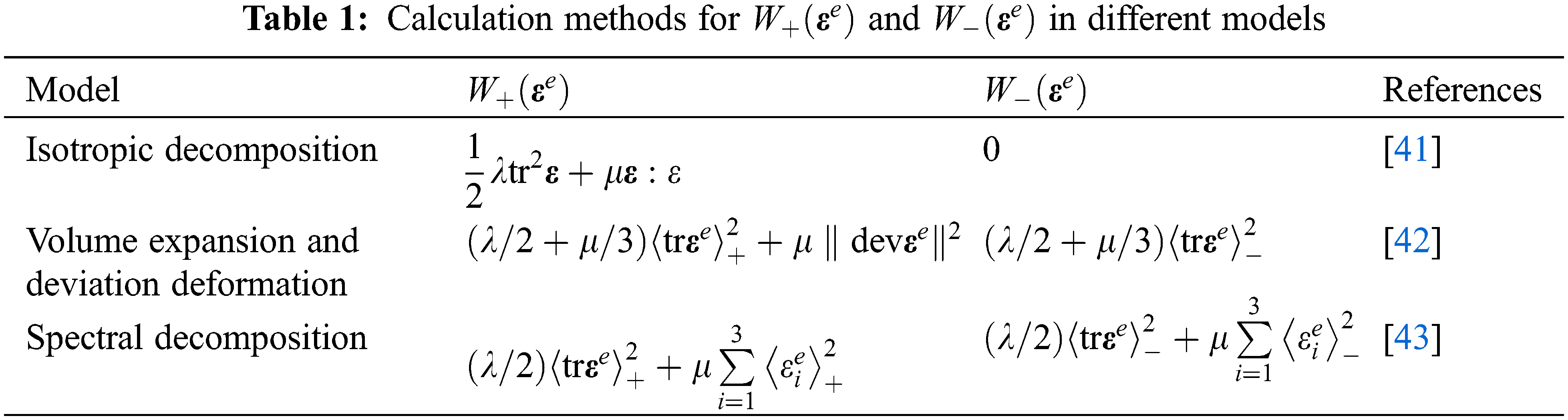
In Table 1,
The isotropic decomposition model assumes that all energy contributes to phase-field evolution, meaning that all strain energy accumulated during deformation drives the phase-field evolution. The volumetric expansion and deviatoric deformation model assumes that only volumetric expansion and deviatoric deformation contribute to phase-field evolution, while volumetric compression does not. The spectral decomposition model assumes that only pure tensile loading during deformation contribute to phase-field evolution and crack propagation. In concrete materials under compressive loading, crack propagation behavior is described by the wing crack propagation model. Cracks randomly initiate within the material domain, and as the load increases, the crack tips begin to propagate under principal tensile stress. The direction of crack propagation gradually becomes parallel to the loading direction. This indicates that the crack propagation behavior in concrete is mainly related to tensile stress and volumetric expansion deformation. Therefore, the spectral decomposition model is adopted in this study to describe the damage and failure behavior of concrete.
3 Elastoplastic Constitutive Model
3.1 Yield Function, Plastic Hardening, and Flow Criterion
The evolution of the phase-field variable is governed by the phase-field driving force generated by the elastoplastic constitutive model. In the numerical algorithm for the phase-field model, the first step involves iteratively calculating the undamaged stress within the framework of the elastoplastic constitutive model. Then, the generated phase-field driving force is used to compute the phase-field variable that satisfies the phase-field governing equation, and finally, the stress of the damaged material is updated. Therefore, this section will introduce the yield function, plastic hardening behavior, and flow rule within the framework of elastoplastic theory.
Within the framework of elastoplastic theory, the total strain rate
where,
where,
where,
where,
Figure 1: The yield function in the principal stress space
In the damage and failure process of concrete, a characteristic behavior of initial hardening followed by softening is typically observed. In the phase-field model, the softening behavior of the material response is generally captured by the evolution of the phase-field variable. Therefore, within the elastoplastic constitutive model, it is sufficient to define only the hardening behavior of the material. This section adopts a nonlinear hardening rate:
where,

Figure 2: Roles of parameters
During the impact deformation process of concrete, differences in strength, elastic modulus, and Poisson’s ratio compared to static conditions are observed. Existing research indicates that dynamic loading has a minimal effect on the initial elastic modulus during the elastic deformation phase of concrete, while the strength of concrete is sensitive to the strain rate of loading. In Eq. (16), the parameter c influences the magnitude of the initial yield stress of concrete. In this study, it is assumed that the rate dependency of c results in a rate-dependent response of concrete strength. An independent rate-dependent function is introduced to model the sensitivity of concrete strength to strain rate:
where,
3.2 Equivalent Elastic Parameters of Concrete
In this study the microstructure of concrete is not considered. Instead, concrete is treated as a homogeneous material based on Mori-Tanaka theory [45] and Eshelby’s equivalent inclusion theory [46]. It is assumed that concrete is composed of two phases: the cement mortar matrix phase (phase 0) and the coarse aggregate phase (phase 1). The bulk modulus, shear modulus, and Poisson’s ratio of the cement mortar are denoted as
where,
The elastic modulus and Poisson’s ratio of the cement mortar are 28 GPa and 0.2, respectively, while those of the coarse aggregate are 42 GPa and 0.16, respectively. Assuming the volume fraction of the coarse aggregate is 0.3, the equivalent elastic modulus and Poisson’s ratio of the homogenized concrete are 31 GPa and 0.19, respectively.
In this section, the implementation of the developed model in ABAQUS is first described. Then, the role of the phase field viscosity parameter
4.1 Calculation Process of the Phase-Field Model in ABAQUS
This study utilizes ABAQUS finite element simulation software, and its nonlinear solver is used to solve the elastoplastic constitutive model and the phase-field governing equation. In ABAQUS, the implementation of the phase-field model follows a general computational procedure outlined by Molnár et al. [47,48]. In explicit dynamic simulations, the coupled solution of the displacement subsystem and the phase-field subsystem is generally achieved through the use of the ABAQUS user subroutine VUMAT and the user defined element (VUEL). This approach allows for the concurrent solving of the mechanical and phase-field equations within a unified framework. The overall computational scheme is illustrated in Fig. 3.

Figure 3: Interleaved solution scheme
In both the displacement subsystem and the phase field subsystem, C3D8T elements are employed. The displacement subsystem utilizes degrees of freedom (DOFs) 1, 2, 3, and 11, whereas the phase field subsystem exclusively uses DOF 11. During the time interval, historical data will first be read within the displacement subsystem. Subsequently, the current time step’s undamaged stress will be computed using an iterative algorithm based on the elastoplastic constitutive model. The phase field driving force will be calculated and stored in the State Dependent Variables (SDV), while the damage stress will be computed via the energy degradation function and returned to VUMAT. In the phase field subroutine, the phase field variable for the current time step will be calculated based on the historical phase field driving force. At the conclusion of the current staggered solution step, VUSDFLD will be invoked to read the phase field driving force stored in the SDV, and VUFIELD will be used to retrieve the phase field variable corresponding to DOF 11 from the phase field subsystem. This procedure facilitates the exchange of data between the two subsystems.
To illustrate the specific role of the phase field viscosity coefficient, this section presents numerical experiments on an element to test the uniaxial tensile local stress-strain responses under various phase field viscosity parameters (Fig. 4). The critical energy release rate

Figure 4: Effect of the viscosity coefficient on the stress-strain response and phase field evolution of the element: (a) Effect of the viscosity coefficient on the stress-strain; (b) Effect of the viscosity coefficient on phase field evolution

Since the energy decomposition models in Table 1 yield identical results under tensile conditions, the uniaxial tensile test of the element provides a convenient means to discuss the effect of the phase field viscosity coefficient. As observed in Fig. 4, with an increase in the phase field viscosity parameter, the phase field evolution slows down, and the stress increases. An increase in the phase field viscosity parameter physically represents a higher viscous resistance to crack propagation, which requires a greater external force to initiate and advance cracks. The energy threshold

Figure 5: Effect of
As shown in Fig. 5, the introduction of
4.3 Numerical Experiment of the Split Hopkinson Pressure Bar [49]
The testing of the dynamic mechanical properties of materials under impact is typically conducted using the Split Hopkinson Pressure Bar (SHPB) (Fig. 6). The SHPB apparatus consists of an impact bar, an incident bar, and a transmission bar, with the lengths of the incident and transmission bars selected based on the dimensions of the specimen. The specimen is placed between the incident and transmission bars. Upon high-speed impact of the impact bar onto the incident bar, an incident pulse is generated within the incident bar. This incident pulse is captured by strain gauges on the incident bar. After reflecting multiple times within the specimen to reach a state of stress equilibrium, a portion of the pulse is transmitted into the transmission bar, where it is captured by strain gauges to form the transmitted pulse. Another portion is reflected back into the incident bar, forming a reflected pulse, which is also recorded by strain gauges. This study follows the experimental setup reported by Al-Salloum et al. [49]. For the SHPB apparatus, the impact bar length is 1 m, the incident bar length is 6 m, and the transmission bar length is 4 m. The bar diameter is 75 mm, while the specimen diameter is 63 mm, with a length of 31.5 mm. The longitudinal wave speed in the bars is 5200 m/s, and the elastic modulus is 208 GPa. The waveform diagram is shown in Fig. 7.

Figure 6: Numerical experiments of SHPB

Figure 7: The waveform diagram in SHPB
As seen in Fig. 7, the reflected pulse forms a strain rate platform, indicating that the sample in the simulated experiment has reached a constant strain rate. Under the assumption of dynamic stress equilibrium and based on one-dimensional stress wave theory, the dynamic stress-strain response and the average strain rate of the specimen can be calculated using the following equations:
where,
Since concrete is a man-made composite material with inherent defects, defect elements are introduced in the finite element analysis to approximate these natural defects. The percentage of defect elements is set at 1%, and the defect element insertion is based on a random distribution algorithm, the algorithm first calculates the number of defect elements based on the total number of elements and their proportions, then the algorithm randomly selects element IDs, marks them as defect elements, and stores these IDs in memory. The defect elements are then collected into a set of elements and assigned defect element properties. The assignment of defect element properties is accomplished by predefining the values of historical variables. Specifically, the historical variables are written to the material property array of the VUMAT subroutine. For non-defective elements, the corresponding positions in the material property array are set to 0, allowing for a clear distinction between defect and non-defective elements. The model proposed in this study is used to analyze the macroscopic dynamic mechanical response, crack propagation, and damage failure behavior of concrete under different strain rates. The analysis parameters are presented in Table 3, and a comparison of the dynamic stress-strain curves is shown in Fig. 8.


Figure 8: Comparison of model predicted curves with experimental curves [49]
From the Fig. 8, it can be observed that the model accurately captures the evolution of various stages of concrete under impact loading, including elastic response, plastic hardening, and damage evolution. The model effectively describes the nonlinear hardening and softening behavior of concrete. Since the macroscopic response of concrete under impact loading is governed by crack propagation behavior, Fig. 9 presents the distribution of the damage field at different moments under a strain rate of 178 s−1.

Figure 9: Phase field distribution in concrete
As shown in the Fig. 9, during the initial stages of loading, local stress concentrations occur around internal defects in the concrete, leading to the initiation of microcracks around the defect elements. As the load increases, the initial microcracks continue to expand, gradually approaching, connecting, and merging to form larger crack clusters. This stage is primarily dominated by shear crack propagation, with crack directions inclined relative to the loading axis, typically at a 45-degree angle. This inclination is driven by shear stress under uniaxial compression, guiding the cracks to propagate in the oblique direction. Subsequently, the microcracks progressively merge into macroscopic cracks, which appear as vertical cracks along the loading direction. When the load continues to increase, the axial compressive stress increases, triggering transverse tensile stress, which causes lateral deformation in the material and further induces tensile cracks along the axial direction. Eventually, macroscopic cracks that span the sample cross-section form, leading to material failure. As the peak strength is approached, the macroscopic cracks expand rapidly, manifesting as cracks perpendicular to the loading direction and accompanied by significant lateral expansion effects. At this point, internal energy is released rapidly, accelerating the crack propagation, which ultimately leads to splitting failure of the concrete sample and overall material failure. This indicates that tensile deformation during the deformation process controls the failure of the concrete. Fig. 10 shows the distribution of the equivalent plastic strain at the corresponding time step.

Figure 10: Equivalent plastic strain distribution in concrete
From Fig. 10, it can be seen that during the deformation process of concrete, nonuniform deformation occurs at defect locations, leading to localized plastic deformation. The accumulation of elastic and plastic energy drives the evolution of the phase-field. During this process, the equivalent plastic strain of the concrete evolves from zero to eventual saturation, which can be divided into the following stages: (1) initial elastic stage: concrete remains in the elastic deformation state, with a linear stress-strain relationship and zero equivalent plastic strain; (2) microcrack nucleation stage: As the load increases, localized stress concentrations trigger the nucleation of microcracks in weak interface regions, and the equivalent plastic strain begins to increase gradually; (3) microcrack propagation and aggregation stage: microcracks propagate and gradually aggregate into larger crack clusters, accompanied by significant shear sliding effects, leading to a substantial increase in equivalent plastic strain, which extends to the macroscopic scale; (4) macroscopic crack formation stage: microcracks further coalesce into macroscopic cracks that propagate in the direction of loading, causing a rapid increase in equivalent plastic strain, particularly at the crack tip, where plastic strain accumulation accelerates significantly; (5) failure stage: as loading approaches the peak strength, macroscopic cracks expand rapidly, and the equivalent plastic strain reaches its peak, approaching saturation, indicating that the plastic deformation process is near completion and the material enters a failure state. Additionally, the parameters of the phase-field model can introduce uncertainties into the simulation results. Fig. 11 presents the crack evolution and dynamic stress-strain curve responses for different phase field length parameter.

Figure 11: Effect of different phase field length parameter on the stress-strain curve and failure behavior of concrete
As shown in Fig. 11, the phase field length parameter controls the width of the diffuse crack zone. As
The following conclusions were obtained from this study:
1. The phase-field governing equation is derived based on the variational approach of the phase-field model, where the viscous resistance to the phase-field evolution is introduced. The viscous resistance increases with the increase of the phase field viscosity coefficient. The phase-field viscosity coefficient can explain the viscous effects during crack propagation. In addition, this study elucidates the role of the energy threshold and the energy control parameters, with both factors jointly contributing to the effective driving force for the phase field evolution.
2. A rate-dependent expression for nonlinear hardening and cohesive strength is defined within the elastoplastic constitutive model of concrete. The rate-dependent evolution of cohesive strength leads to different elastoplastic phase field driving forces at different strain rates. This feature helps to explain the different failure responses of concrete at different strain rates.
3. The impact damage and failure behavior of concrete are analyzed based on the phase-field model and the developed rate-dependent elastoplastic constitutive model. The analysis reveals the evolution path of microcracks from localized damage accumulation to macroscopic crack formation. It also illustrates the combined influence of shear cracking and axial tensile cracking on plastic strain accumulation. Under impact loading, microcracks nucleate at internal defects, and as the load increases, the cracks propagate along the loading direction. These cracks merge with defects along the propagation path to form a main crack, ultimately leading to the overall failure of the concrete, with the main crack propagating along the loading direction.
Acknowledgement: None.
Funding Statement: None.
Author Contributions: The authors confirm contribution to the paper as follows: study conception and design: Wei Zhang, Fulai Zhang; analysis and interpretation of results: Zhishui Sheng, Hong Jiang; draft manuscript preparation: Gang Liu. All authors reviewed the results and approved the final version of the manuscript.
Availability of Data and Materials: The data that support the findings of this study are available from the corresponding author upon reasonable request.
Ethics Approval: Not applicable.
Conflicts of Interest: The authors declare no conflicts of interest to report regarding the present study.
References
1. Dobiszewska M, Bagcal O, Beycioğlu A, Goulias D, Köksal F, Płomiński B, et al. Utilization of rock dust as cement replacement in cement composites: an alternative approach to sustainable mortar and concrete productions. J Build Eng. 2023;69:106180. doi:10.1016/j.jobe.2023.106180. [Google Scholar] [CrossRef]
2. Li X, Qin D, Hu Y, Ahmad W, Ahmad A, Aslam F, et al. A systematic review of waste materials in cement-based composites for construction applications. J Build Eng. 2022;45:103447. doi:10.1016/j.jobe.2021.103447. [Google Scholar] [CrossRef]
3. Roy T, Matsagar V. Multi-hazard analysis and design of structures: status and research trends. Struct Infrastruct Eng. 2023;19(6):845–74. doi:10.1080/15732479.2021.1987481. [Google Scholar] [CrossRef]
4. Urlainis A, Ornai D, Levy R, Vilnay O, Shohet IM. Loss and damage assessment in critical infrastructures due to extreme events. Saf Sci. 2022;147:105587. doi:10.1016/j.ssci.2021.105587. [Google Scholar] [CrossRef]
5. Jiang Z, He B, Zhu X, Ren Q, Zhang Y. State-of-the-art review on properties evolution and deterioration mechanism of concrete at cryogenic temperature. Constr Build Mater. 2020;257:119456. doi:10.1016/j.conbuildmat.2020.119456. [Google Scholar] [CrossRef]
6. Gribniak V, Kaklauskas G, Bacinskas D. Shrinkage in reinforced concrete structures: a computational aspect. J Civ Eng Manag. 2008;14(1):49–60. doi:10.3846/1392-3730.2008.14.49-60. [Google Scholar] [CrossRef]
7. Li Y, Jiang S, Lan R. Coupling effect of cryogenic freeze-thaw cycles and chloride ion erosion effect in pre-cracked reinforced concrete. Struct Durability Health Monitor. 2024;18(3):255–76. doi:10.32604/sdhm.2024.047776. [Google Scholar] [CrossRef]
8. Gao Y, Sun H. Influence of initial defects on crack propagation of concrete under uniaxial compression. Constr Build Mater. 2021;277:122361. doi:10.1016/j.conbuildmat.2021.122361. [Google Scholar] [CrossRef]
9. Fan H, Yu H, Ma H. Dynamic increase factor (DIF) of concrete with SHPB tests: review and systematic analysis. J Build Eng. 2023;79:107666. doi:10.1016/j.jobe.2023.107666. [Google Scholar] [CrossRef]
10. Hassan M, Wille K. Direct tensile behavior of steel fiber reinforced ultra-high performance concrete at high strain rates using modified split Hopkinson tension bar. Compos Part B: Eng. 2022;246:110259. doi:10.1016/j.compositesb.2022.110259. [Google Scholar] [CrossRef]
11. Yang D, He X, Liu X, Deng Y, Huang X. A peridynamics-based cohesive zone model (PD-CZM) for predicting cohesive crack propagation. Int J Mech Sci. 2020;184:105830. doi:10.1016/j.ijmecsci.2020.105830. [Google Scholar] [CrossRef]
12. Elices M, Guinea GV, Gomez J, Planas J. The cohesive zone model: advantages, limitations and challenges. Eng Fract Mech. 2002;69(2):137–63. doi:10.1016/S0013-7944(01)00083-2. [Google Scholar] [CrossRef]
13. Park K, Paulino GH. Cohesive zone models: a critical review of traction-separation relationships across fracture surfaces. Appl Mech Rev. 2011;64(6):60802. doi:10.1115/1.4023110. [Google Scholar] [CrossRef]
14. Zi G, Belytschko T. New crack-tip elements for XFEM and applications to cohesive cracks. Int J Numer Methods Eng. 2003;57(15):2221–40. doi:10.1002/nme.849. [Google Scholar] [CrossRef]
15. Wciślik W, Pała T. Selected aspects of cohesive zone modeling in fracture mechanics. Metals. 2021;11(2):302. doi:10.3390/met11020302. [Google Scholar] [CrossRef]
16. Abdulridha Lateef H, Mahmood Laftah R, Abdulrazzaq Jasim N. Investigation of crack propagation in plain concrete using phase-field model. Mater Today: Proc. 2022;57:375–82. [Google Scholar]
17. Li G, Tan KH, Fung TC, Yu QJ, May M. A coupled dynamic cohesive zone model for FRP-concrete mixed-mode separation. Compos Struct. 2021;268(7):113872. doi:10.1016/j.compstruct.2021.113872. [Google Scholar] [CrossRef]
18. Abbas M, Bary B, Jason L. A 3D mesoscopic frictional cohesive zone model for the steel-concrete interface. Int J Mech Sci. 2023;237(4):107819. doi:10.1016/j.ijmecsci.2022.107819. [Google Scholar] [CrossRef]
19. Xia X, Chen F, Gu X, Fang N, Zhang Q. Interfacial debonding constitutive model and XFEM simulation for mesoscale concrete. Comput Struct. 2021;242(7):106373. doi:10.1016/j.compstruc.2020.106373. [Google Scholar] [CrossRef]
20. Jin H, Yu S. Study on corrosion-induced cracks for the concrete with transverse cracks using an improved CDM-XFEM. Constr Build Mater. 2022;318(9):126173. doi:10.1016/j.conbuildmat.2021.126173. [Google Scholar] [CrossRef]
21. Rabczuk T, Belytschko T. Cracking particles: a simplified meshfree method for arbitrary evolving cracks. Int J Numer Methods Eng. 2004;61(13):2316–43. doi:10.1002/nme.v61:13. [Google Scholar] [CrossRef]
22. Rabczuk T, Belytschko T. A three-dimensional large deformation meshfree method for arbitrary evolving cracks. Comput Methods Appl Mech Eng. 2007;196(29–30):2777–99. [Google Scholar]
23. Cervera M, Barbat GB, Chiumenti M, Wu J. A comparative review of XFEM, mixed FEM and phase-field models for quasi-brittle cracking. Arch Comput Methods Eng. 2022;29(2):1009–83. doi:10.1007/s11831-021-09604-8. [Google Scholar] [CrossRef]
24. Piska R, Sivadas K, Boyina K, Vuppuluri A, Chaurasia A, Parimi C, et al. Recent trends in computational damage models: an overview. Theor Appl Fract Mech. 2024;132:104494. doi:10.1016/j.tafmec.2024.104494. [Google Scholar] [CrossRef]
25. Yin BB, Sun WK, Zhang Y, Liew KM. Modeling via peridynamics for large deformation and progressive fracture of hyperelastic materials. Comput Methods Appl Mech Eng. 2023;403:115739. doi:10.1016/j.cma.2022.115739. [Google Scholar] [CrossRef]
26. Wu J. A unified phase-field theory for the mechanics of damage and quasi-brittle failure. J Mech Phys Solids. 2017;103(4):72–99. doi:10.1016/j.jmps.2017.03.015. [Google Scholar] [CrossRef]
27. Li P, Li W, Li B, Yang S, Shen Y, Wang Q, et al. A review on phase field models for fracture and fatigue. Eng Fract Mech. 2023;289:109419. doi:10.1016/j.engfracmech.2023.109419. [Google Scholar] [CrossRef]
28. Chen L. Phase-field models for microstructure evolution. Annu Rev Mater Res. 2002;32(1):113–40. doi:10.1146/annurev.matsci.32.112001.132041. [Google Scholar] [CrossRef]
29. Borden MJ, Verhoosel CV, Scott MA, Hughes TJ, Landis CM. A phase-field description of dynamic brittle fracture. Comput Methods Appl Mech Eng. 2012;217(8):77–95. doi:10.1016/j.cma.2012.01.008. [Google Scholar] [CrossRef]
30. Kuhn C, Schlüter A, Müller R. On degradation functions in phase field fracture models. Comput Mater Sci. 2015;108(4):374–84. doi:10.1016/j.commatsci.2015.05.034. [Google Scholar] [CrossRef]
31. Clayton JD, Knap J. A geometrically nonlinear phase field theory of brittle fracture. Int J Fract. 2014;189(2):139–48. doi:10.1007/s10704-014-9965-1. [Google Scholar] [CrossRef]
32. Zhang Y, Guo J, Shu Z, Guan Y, Ademiloye AS. Fracture simulation of fiber reinforced composite panels with holes. Compos Struct. 2025;351(9):118627. doi:10.1016/j.compstruct.2024.118627. [Google Scholar] [CrossRef]
33. Hai L, Zhang H, Wriggers P, Huang Y, Zhuang X, Xu S. 3D concrete fracture simulations using an explicit phase field model. Int J Mech Sci. 2024;265:108907. doi:10.1016/j.ijmecsci.2023.108907. [Google Scholar] [CrossRef]
34. Sadighi A, Maghami E, Khaneghahi MH, Kamireddi D, Rahmaninezhad SA, Farnam YA, et al. Fracture analysis of multifunctional fiber-reinforced concrete using phase-field method. Int J Solids Struct. 2023;283(5):112493. doi:10.1016/j.ijsolstr.2023.112493. [Google Scholar] [CrossRef]
35. Vajari SA, Neuner M, Arunachala PK, Linder C. Investigation of driving forces in a phase field approach to mixed mode fracture of concrete. Comput Methods Appl Mech Eng. 2023;417(11):116404. doi:10.1016/j.cma.2023.116404. [Google Scholar] [CrossRef]
36. Teichert GH, Garikipati K. Machine learning materials physics: surrogate optimization and multi-fidelity algorithms predict precipitate morphology in an alternative to phase field dynamics. Comput Methods Appl Mech Eng. 2019;344:666–93. doi:10.1016/j.cma.2018.10.025. [Google Scholar] [CrossRef]
37. Li W, Yang T, Liu C, Huang Y, Chen C, Pan H, et al. Optimizing piezoelectric nanocomposites by high-throughput phase-field simulation and machine learning. Adv Sci. 2022;9(13):2105550. doi:10.1002/advs.v9.13. [Google Scholar] [CrossRef]
38. Francfort GA, Marigo J. Revisiting brittle fracture as an energy minimization problem. J Mech Phys Solids. 1998;46(8):1319–42. doi:10.1016/S0022-5096(98)00034-9. [Google Scholar] [CrossRef]
39. Wang T, Liu ZL, Cui YN, Ye X, Liu XM, Tian R, et al. A thermo-elastic-plastic phase-field model for simulating the evolution and transition of adiabatic shear band. Part I. Theory and model calibration. Eng Fract Mech. 2020;232:107028. doi:10.1016/j.engfracmech.2020.107028. [Google Scholar] [CrossRef]
40. Wu J, Nguyen VP, Nguyen CT, Sutula D, Sinaie S, Bordas SP. Phase-field modeling of fracture. Adv Appl Mech. 2020;53:1–183. doi:10.1016/bs.aams.2019.08.001. [Google Scholar] [CrossRef]
41. Bui TQ, Hu X. A review of phase-field models, fundamentals and their applications to composite laminates. Eng Fract Mech. 2021;248(8):107705. doi:10.1016/j.engfracmech.2021.107705. [Google Scholar] [CrossRef]
42. Steinke C, Storm J, Kaliske M. Energetically motivated crack orientation vector for phase-field fracture with a directional split. Int J Fract. 2022;237(1):15–46. doi:10.1007/s10704-022-00633-3. [Google Scholar] [CrossRef]
43. Wang F, Shao J, Huang H. A phase-field modeling method for the mixed-mode fracture of brittle materials based on spectral decomposition. Eng Fract Mech. 2021;242(1):107473. doi:10.1016/j.engfracmech.2020.107473. [Google Scholar] [CrossRef]
44. Aldakheel F. A microscale model for concrete failure in poro-elasto-plastic media. Theor Appl Fract Mech. 2020;107:102517. doi:10.1016/j.tafmec.2020.102517. [Google Scholar] [CrossRef]
45. Yang C, Huang R. A two-phase model for predicting the compressive strength of concrete. Cem Concr Res. 1996;26(10):1567–77. doi:10.1016/0008-8846(96)00137-8. [Google Scholar] [CrossRef]
46. Eshelby JD. The determination of the elastic field of an ellipsoidal inclusion, and related problems. Proc R Soc Lond A. 1957;241(1226):376–96. doi:10.1098/rspa.1957.0133. [Google Scholar] [CrossRef]
47. Molnár G, Gravouil A. 2D and 3D Abaqus implementation of a robust staggered phase-field solution for modeling brittle fracture. Finite Elem Anal Des. 2017;130:27–38. doi:10.1016/j.finel.2017.03.002. [Google Scholar] [CrossRef]
48. Msekh MA, Sargado JM, Jamshidian M, Areias PM, Rabczuk T. Abaqus implementation of phase-field model for brittle fracture. Comput Mater Sci. 2015;96(8):472–84. doi:10.1016/j.commatsci.2014.05.071. [Google Scholar] [CrossRef]
49. Al-Salloum Y, Almusallam T, Ibrahim SM, Abbas H, Alsayed S. Rate dependent behavior and modeling of concrete based on SHPB experiments. Cem Concr Compos. 2015;55(2):34–44. doi:10.1016/j.cemconcomp.2014.07.011. [Google Scholar] [CrossRef]
Cite This Article
 Copyright © 2025 The Author(s). Published by Tech Science Press.
This work is licensed under a Creative Commons Attribution 4.0 International License , which permits unrestricted use, distribution, and reproduction in any medium, provided the original work is properly cited.
 Downloads
 Citation Tools