
 Submit a Paper
 Propose a Special lssue
 Open Access
ARTICLE

Influence of Welding Residual Stress on the Structural Behaviour of Large-Span Steel Tube Arch Rib
1 State Key Laboratory of Mountain Bridge and Tunnel Engineering, Chongqing Jiaotong University, Chongqing, 400074, China
2 School of Civil Engineering, Chongqing Jiaotong University, Chongqing, 400074, China
3 Guangxi Road and Bridge Engineering Group Co., Ltd., Nanning, 530200, China
* Corresponding Author: Renzhang Yan. Email:
Structural Durability & Health Monitoring 2025, 19(4), 1037-1056. https://doi.org/10.32604/sdhm.2025.058780
Received 20 September 2024; Accepted 12 December 2024; Issue published 30 June 2025
 View Full Text
 Download PDF
Abstract
The steel tube arch rib in a large-span concrete-filled steel tube arch bridge has a large span and diameter, which also leads to a larger weld seam scale. Large-scale welding seams will inevitably cause more obvious welding residual stress (WRS). For the purpose of studying the influence of WRS from large-scale welding seam on the mechanical properties of steel tube arch rib during arch rib splicing, test research and numerical simulation analysis on the WRS in arch rib splicing based on the Guangxi Pingnan Third Bridge, which is the world’s largest span concrete-filled steel tube arch bridge, were conducted in this paper, and the distribution pattern of WRS at the arch rib splicing joint was obtained. Subsequently, the WRS was introduced into the mechanical performance analysis of joints and structures to analyze its effects. The findings reveal that the distribution of WRS in the arch rib is greatly influenced by the rib plate, and the axial WRS in the heat-affected zone are primarily tensile, while the circumferential WRS are distributed in an alternating pattern of tensile and compressive stresses along the circumferential direction of the main tube. Under the influence of WRS, the ultimate bearing capacity of the joint is reduced by 29.4%, the initial axial stiffness is reduced by 4.32%, and the vertical deformation of the arch rib structure is increased by 4.7%.Keywords
As welding technology continually evolves, the reliance on it for the construction of steel structures has grown progressively stronger. However, the welding residual stress (WRS) is inevitably generated in the welding process. The existence of WRS in steel structures can have a considerable effect on strength, fatigue resistance, stiffness, and stability [1–5]. In particular, it will cause instability and cracking of the welded structure during the normal use stage and ultimately diminish the structure’s service life. Numerous scholars have studied the influence of WRS on the structures. For instance, Acevedo et al. [6–8] studied the distribution of WRS at tubular K-joints in bridges and their impact on the fatigue crack propagation of K-joints through experiments and numerical simulations. Huang et al. [9,10] focused on the welding process of bridge joints and found that significant WRS develop at the weld position, with the maximum WRS approximately equal to the yield strength of the material. Klassen et al. [11] analyzed the influence of WRS cyclic redistribution on fatigue strength and pointed out that its redistribution can reduce the impact on fatigue. Cui et al. [12–14] found through research that the WRS greatly reduces the fatigue resistance of steel bridges. Lee et al. [15] analyzed the influence of WRS on the fracture toughness at the intersection of steel tubular joints. Jin et al. [16] analyzed the influence of WRS on the strength and stiffness of concrete-filled steel tubular Y-joints and K-joints, and discovered that when the thickness of the weld leg decreases, the strength and stiffness of the joint decrease, and the WRS generated is also smaller. Chen et al. [17] conducted an analysis of the stability and bearing capacity of an H-section steel arch under the influence of WRS and showed that the WRS would reduce its ultimate bearing capacity. Wei et al. [18,19] investigated the distribution pattern of WRS in corrugated steel web girder, and the results showed that the WRS increases with the decrease in distance from the weld seam. Lu et al. [20] conducted experimental research to analyze the distribution law of WRS at butt-welded thick steel plates used in the bridge. Yan et al. [21,22] combined experimental research and finite element simulation to analyze the distribution pattern of WRS in the sphere-pipe connection weld of welded hollow spherical joint and found that the WRS can reduce the bending stiffness of the joint by more than 10%. Luo et al. [23] found out by means of numerical simulations that WRS can cause premature fracture of welded joints.
The above research shows that the WRS has a non-negligible impact on mechanical properties, especially the stiffness of various joints and the bearing capacity of various steel structures. For the super-large span concrete-filled steel tubular arch bridges, the cumulative effect of errors is more obvious due to the large-scale steel tube arch ribs, and the unfavourable influence of welding on the structures will be more prominent. Although numerous scholars have studied the influence of WRS on different structures, there is little research on the super-large span concrete-filled steel tubular arch bridge. In view of this, this paper relies on the world’s largest span concrete-filled steel tubular arch bridge, the Guangxi Pingnan Third Bridge. The distribution pattern of WRS of the arch rib is clarified based on our research team’s previous research. Then, the WRS is introduced into the mechanical performance analysis of joints and overall structure. The mechanical properties of joints and overall structure under the influence of WRS are analyzed, which can provide a theoretical foundation for the design and construction of similar projects.
As shown in Fig. 1, the Guangxi Pingnan Third Bridge adopts a middle-bearing concrete-filled steel tubular arch structure with a main span of 575 m. It holds the record as the longest-span concrete-filled steel tubular arch bridge. The combination of cable hoisting and cable-stayed segmental suspension is involved in the construction technology. Each arch rib is assembled from 22 welded segments during installation. The segment hoisting process is depicted in Fig. 2. The main chord has a circular steel tube cross-section measuring Φ1400 × 26, and the connection of adjacent chords is by bolting the inner flange first and then welding the outer curved steel plates, which can be seen in Fig. 3. As the size of steel tube is so large, the size of the connecting weld is large too. In Fig. 4, we can see the actual view of the weld seam, whose maximum width can be up to 52 mm, which will inevitably cause significant WRS.
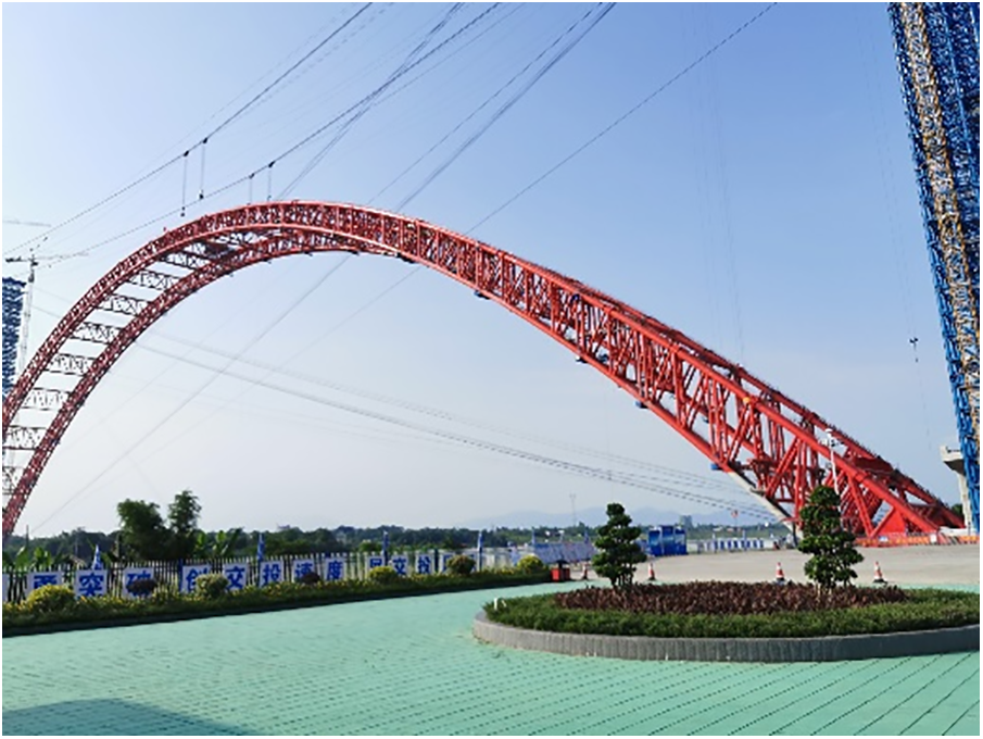
Figure 1: Picture of Guangxi Pingnan Third Bridge
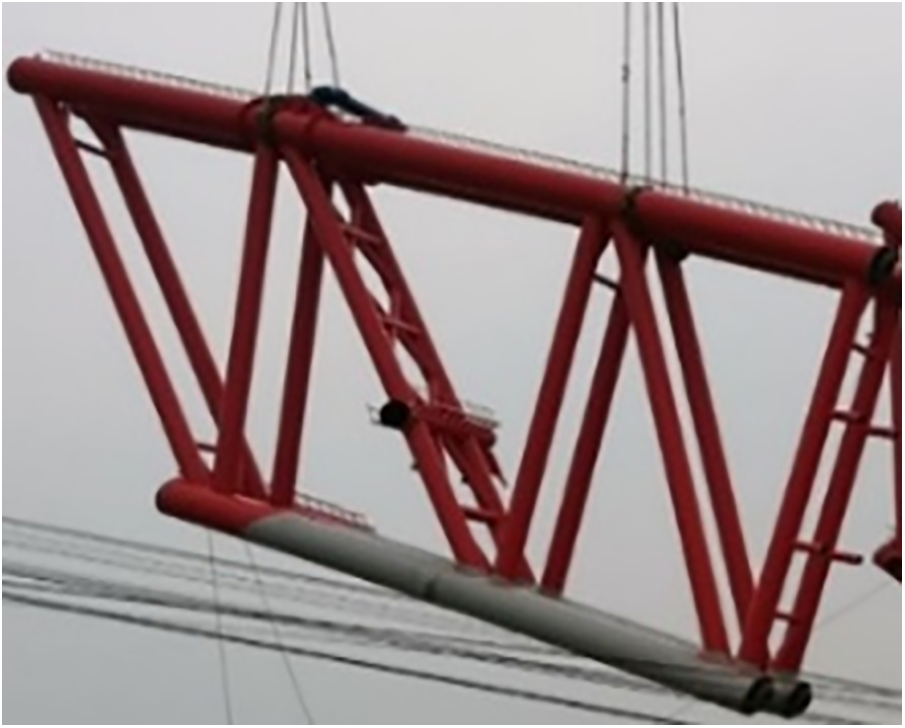
Figure 2: Actual scene of segment hoisting
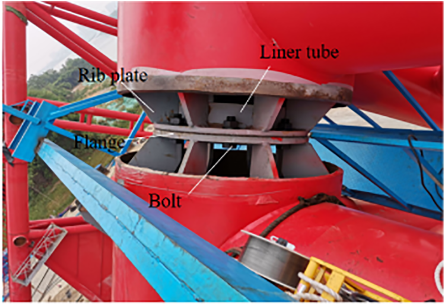
Figure 3: Main chord splicing joint of arch rib
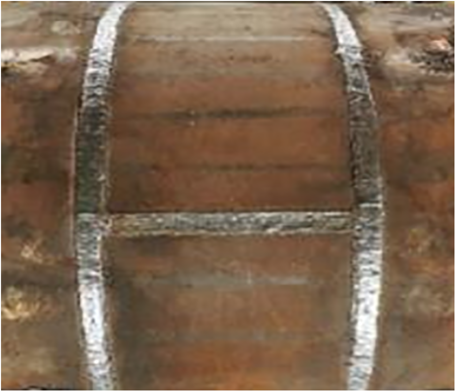
Figure 4: Splicing weld
3 Distribution of WRS in the Connecting Welds with Large Dimension of the Steel Tube Arch Rib Splicing Joint
With the intention of investigating the influence of WRS on the mechanical properties of the arch rib, it is essential to first clarify the distribution pattern of WRS at the splicing joint. In our previous research, our team successfully constructed a full-scale test model of the arch rib splicing joint and employed the blind hole method to measure the WRS of the large-scale welds and their heat-affected zones, and the distribution of WRS could be precisely determined by comparing these results with those obtained through finite element analysis [24]. This paper lists the WRS distribution obtained in the previous study as the basis for the later analysis.
As shown in Fig. 5, the construction of the splicing joint of the steel tube arch rib consists of 4 butt curved plates and some inner connection parts, including 16 rib plates, two sets of flanges, and 1 section of liner tube. The steel tube arch rib and the butt curved plate are made of Q420 steel, and the inner connection parts are made of Q235 steel. The team’s early-stage full-scale test model of the joint is illustrated in Fig. 6. The large-scale welds within the joint consist of two circumferential welds between the arch rib steel tube and the butt curved plate, as well as four transverse welds between the butt curved plates, as displayed in Fig. 7. During the welding process, the four transverse welds are initially welded, followed by the symmetrical welding of the two circumferential welds. The specific welding process is to first perform transverse welds 1 and 2, then transverse welds 3 and 4, and finally, circumferential welds. The transverse welds are welded from left to right; The circumferential welds are welded from the bottom of the test specimen, namely points A to B/B1 to C. The weld seams are welded in four layers, with one to two full passes per layer.
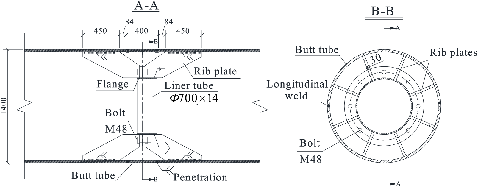
Figure 5: Schematic diagram of splicing joint
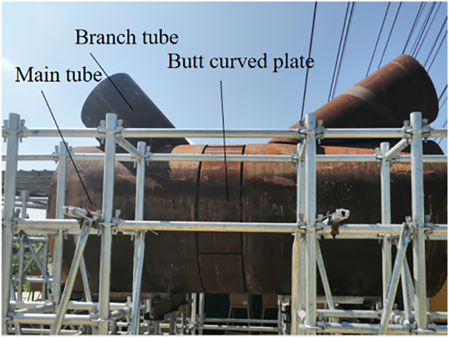
Figure 6: Actual scene diagram of test model
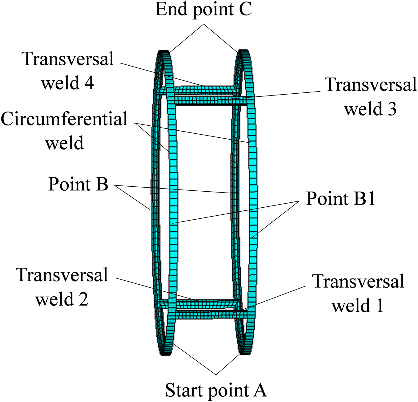
Figure 7: Schematic diagram of welds
After the test specimen has been welded and returned to room temperature, the WRS in the heat-affected zone of the weld is measured using the blind hole method [25,26]. The hole diameter and hole depth in this test were both 1.5 mm, and the minimum distance between holes was 20 mm. The strain energy release coefficients A and B are usually measured in a one-way stress field (σ1 = σ, σ2 = 0), in which case:
Furthermore, it can be concluded that:
where ε1 and ε3 are the strain release in the circumferential and axial directions of the main tube, σ1 and σ2 are the principal stress in the corresponding directions.
In this paper, the strain energy release coefficients A and B are obtained through finite element simulation analysis. An ANSYS finite element model is established by selecting a 75 mm area around the measurement point of the test specimen, with the model size 75 mm × 75 mm × 27 mm. The element type is divided into SOLID45 solid elements, and the element mesh is divided, as shown in Fig. 8.
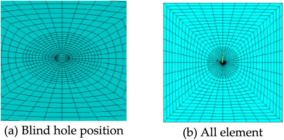
Figure 8: Mesh division diagram of element
Based on symmetry, 1/4 of the weld heat-affected zone is selected along the circumferential direction of the steel tube to analyze the distribution of WRS. A total of 5 paths, totalling 103 measurement points, were set near the weld [24], as shown in Fig. 9. Specifically, two paths parallel to the circumferential weld and located at distances of 10 and 30 mm from the circumferential weld edge are selected as Path 1 and Path 2, a path perpendicular to the circumferential weld and location starting from the circumferential weld edge is selected as Path 3, a path parallel to the transverse weld and located at distances of 30 mm from the transverse weld edge is selected as Path 4, and a path perpendicular to the transverse weld and location starting from the transverse weld edge is selected as Path 5.
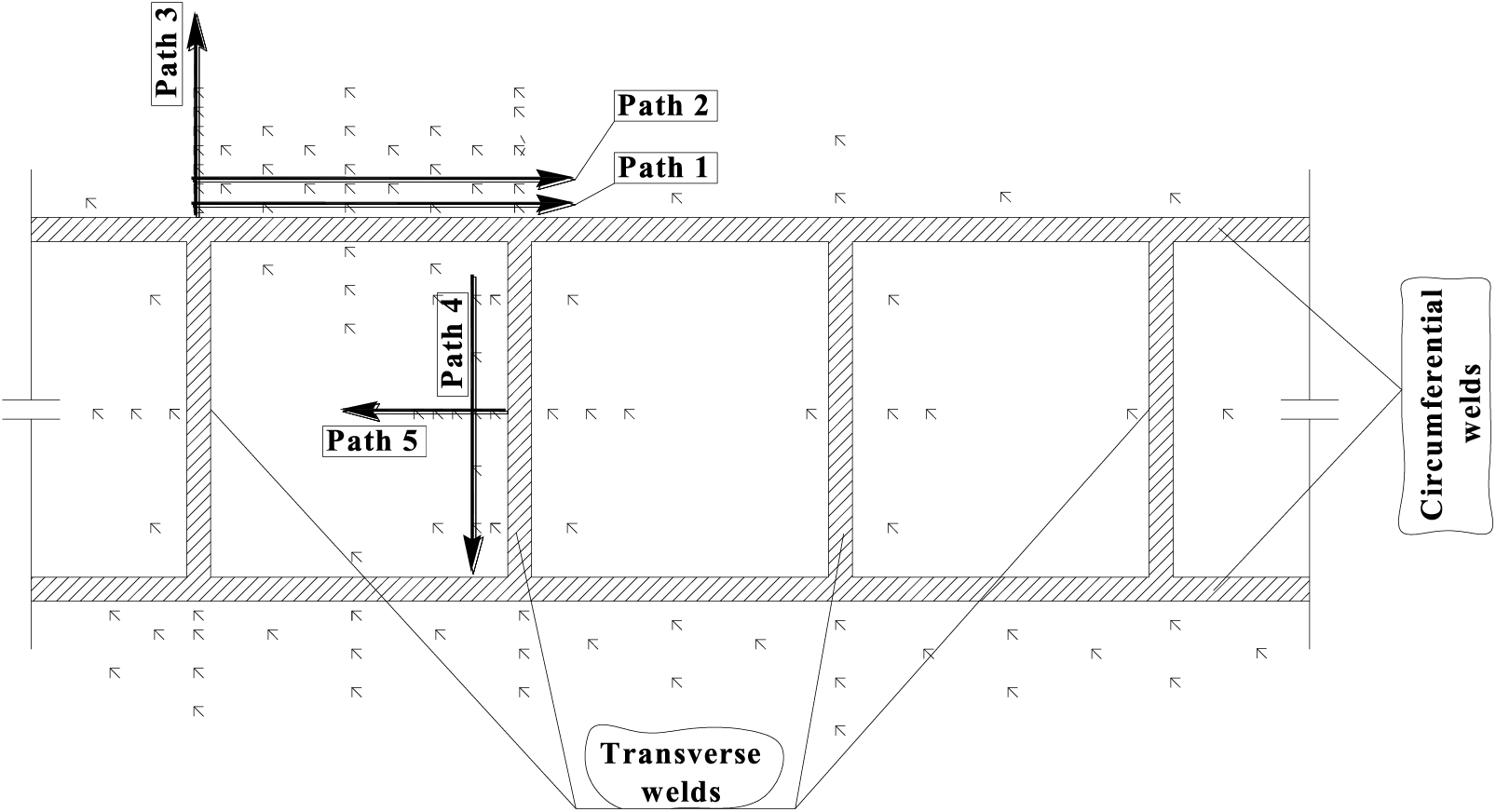
Figure 9: Schematic diagram of measuring point layout path (unit: mm)
3.1.2 Measurement of Welding Residual Deformation
In the course of the welding process, residual deformation occurs in addition to residual stress. Since the arch rib splicing joint is mainly affected by axial load in the overall structure, during the test, an ear plate is attached at every 90° along the circumferential direction of the steel tube, which is 400 mm far from the outer edge of the weld seam. This is used to fix the dial indicator to measure the relative axial deformation caused by welding, as shown in Fig. 10. The four directions of measurement are shown in Fig. 10a and the measurement of deformation on site is shown in Fig. 10b.
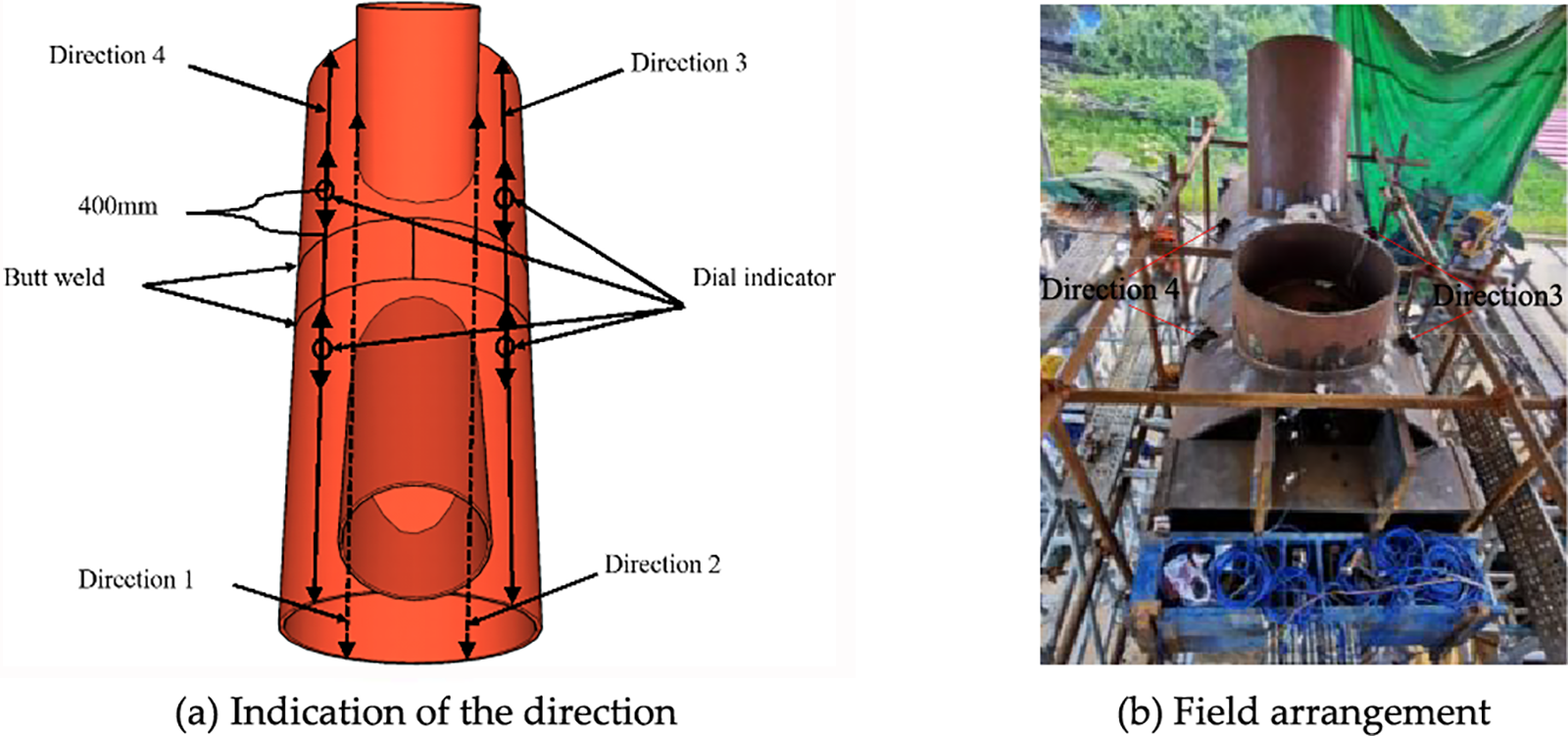
Figure 10: Layout of measuring points for deformation
3.2 Numerical Simulation of WRS
Due to the limited number of measuring points, the measurement results of residual stress and deformation have certain limitations. Therefore, a refined numerical model of the joint is established. Based on a contrastive analysis of the test results and numerical calculations, a more comprehensive summary and analysis of the WRS and deformation in the splicing joint zone were conducted according to the numerical simulation results.
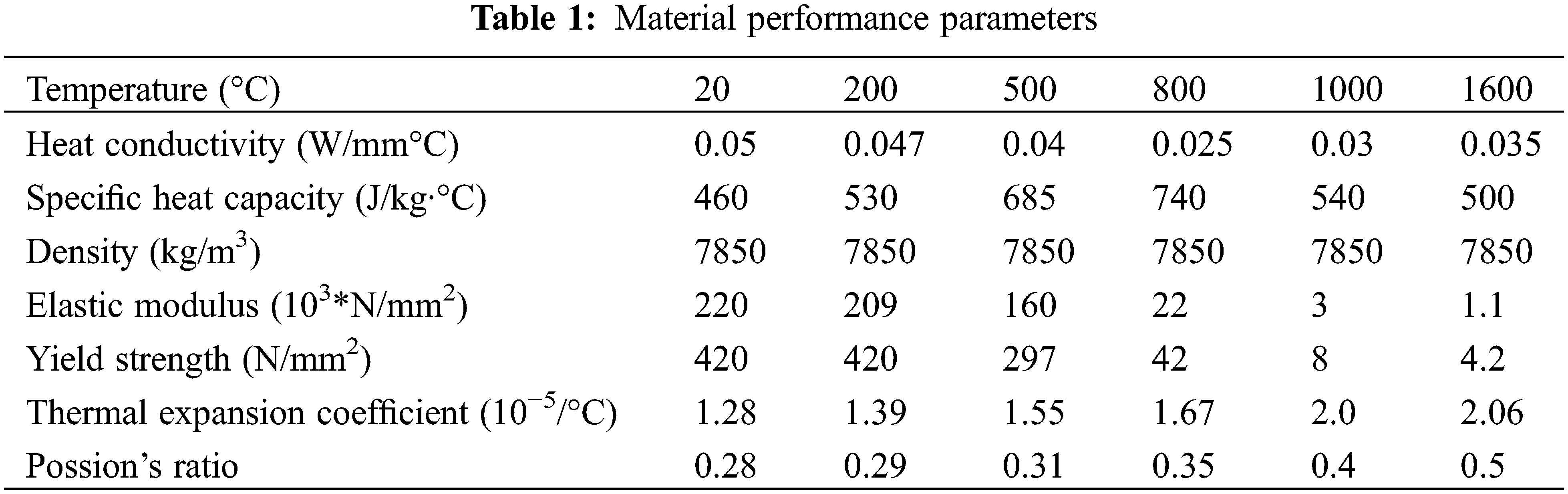
A refined numerical model is established founded on the actual size of connecting parts such as the butt curved plate and rib plate. Mapping mesh is used to divide the mesh, with a particular focus on refining the mesh of the weld and its surrounding zone, as shown in Fig. 11. The variation of thermal physical properties and mechanical properties of Q420 steel with temperature were established [27,28], and the material performance parameters are described in Table 1. The bilinear kinematic hardening model is adopted in finite element analysis, which adopts the Mises yield criterion and kinematic hardening criterion.
Figure 11: Finite element model
The welding process is simulated by ANSYS’s thermal-structure coupling analysis method, and the simulation analysis of the welding temperature field is initially carried out, followed by the stress-strain field being calculated. In performing the thermal analysis calculation, the element type is divided into SOLID70, and a welding heat source loading model, which simulates the formation of weld seams and the input of welding heat by utilizing birth and death element technology, is adopted. Divide the welding into two layers, with 144 welding segments for the circumferential weld and 20 welding segments for the transverse weld in each layer, and the welding process for each two segments is set as a load step. The heat load is applied in the form of body heat generation rate, and convective heat transfer boundary conditions are applied. The body heat generation rate HGEN is calculated according to Eq. (3) [29]:
where η is the welding effective coefficient, this model takes 0.7 [21]; U is the welding voltage, I is the welding current, and they are taken as 30 V, 220 A, respectively, according to the actual parameters in the test process; Aw is the weld cross-section zone; v is the welding speed; Dt is the action time of thermal load.
When analyzing the stress field, the heat conduction element (SOLID70) is converted into the corresponding structural analysis element (SOLID185), and the WRS analysis is carried out by applying the temperature field of the entire welding thermal process as the initial stress to the structural model. The test values and calculation values of the WRS were systematically compared and analyzed in our research team’s previous research [30], and the comparison results are shown in Fig. 12. The error between the test values and the calculated values in Path 1 is small, and the maximum axial WRS are 236 and 245 MPa, with a relative error of no more than 4%. The error between the test values and the calculated values in Path 2 is relatively large, which may be due to deviation in the actual installation position of the rib plate during the test and the fact that each measuring point is farther away from the rib plate, resulting in smaller axial WRS. The test values and the calculated values in Path 3 show a trend of increasing first and then decreasing, with the maximum value of axial tensile stress being 291.8 MPa. Through comprehensive analysis of Paths 1–3, it can be concluded that the test values and the calculated values of circumferential WRS have the same change trend. That is, they rapidly change from tensile stress to compressive stress, and then they close to zero and stabilize, but some values have a large difference, and other initial stresses inside the tube cannot be considered. The maximum axial WRS of the test values and calculated values in Path 4 are 146.9 and 124.6 MPa, with a relative error of 15%. The maximum axial WRS of the test values and calculated values in Path 5 are 297.8 and 243.8 MPa, with a relative error of 18.1%. The change laws of the test values and the calculated values in Paths 4 and 5 are in good agreement, with an average error of around 40 MPa at each measuring point. Overall, the finite element calculation results agree well with the test values, validating the reliability of the finite element model. The subsequent sections will present the complete distribution of WRS based on the numerical simulation results.
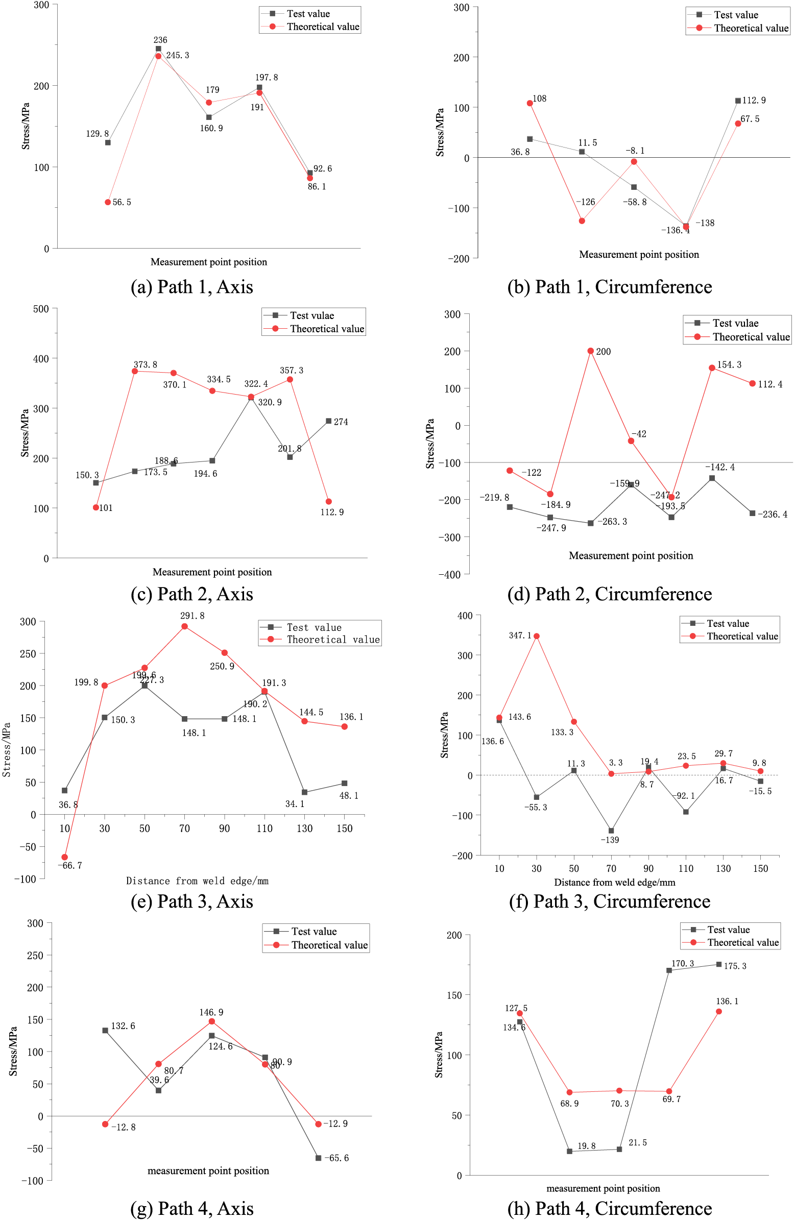
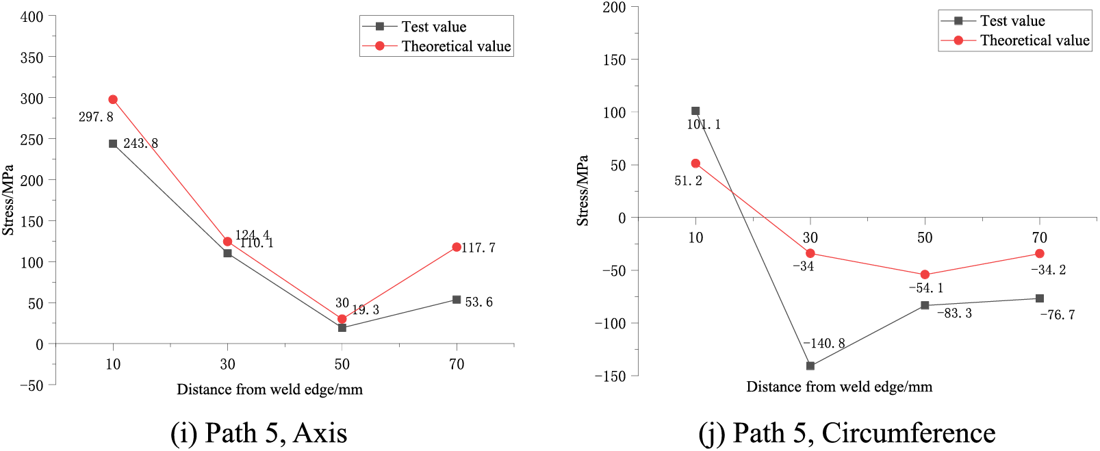
Figure 12: Comparison between test and finite element results
3.3 Distribution of WRS of the Arch Rib
After extracting the finite element calculation results, the maximum axial residual compressive stress near the weld seam of the arch rib splicing joint is found to be 201 MPa, with a corresponding maximum tensile stress of 378 MPa. The maximum circumferential residual compressive stress near the weld seam is 218 MPa, and the maximum tensile stress is 400 MPa. Due to the restraint influence of the built-in rib plate on the steel tube, the larger WRS are concentrated in the area between the rib plate and the circumferential weld.
With the aim of analyzing more intuitively the influence of the built-in rib plate on WRS and the distribution of WRS of the steel tube arch rib splicing joint, three paths parallel to the weld seam and located at distances of 10, 60, and 200 mm from the weld seam edge are re-selected: Paths 1–3. Moreover, two paths perpendicular to the weld in the rib area and the non-rib area are selected: Path 4 and Path 5, as shown in Fig. 13.
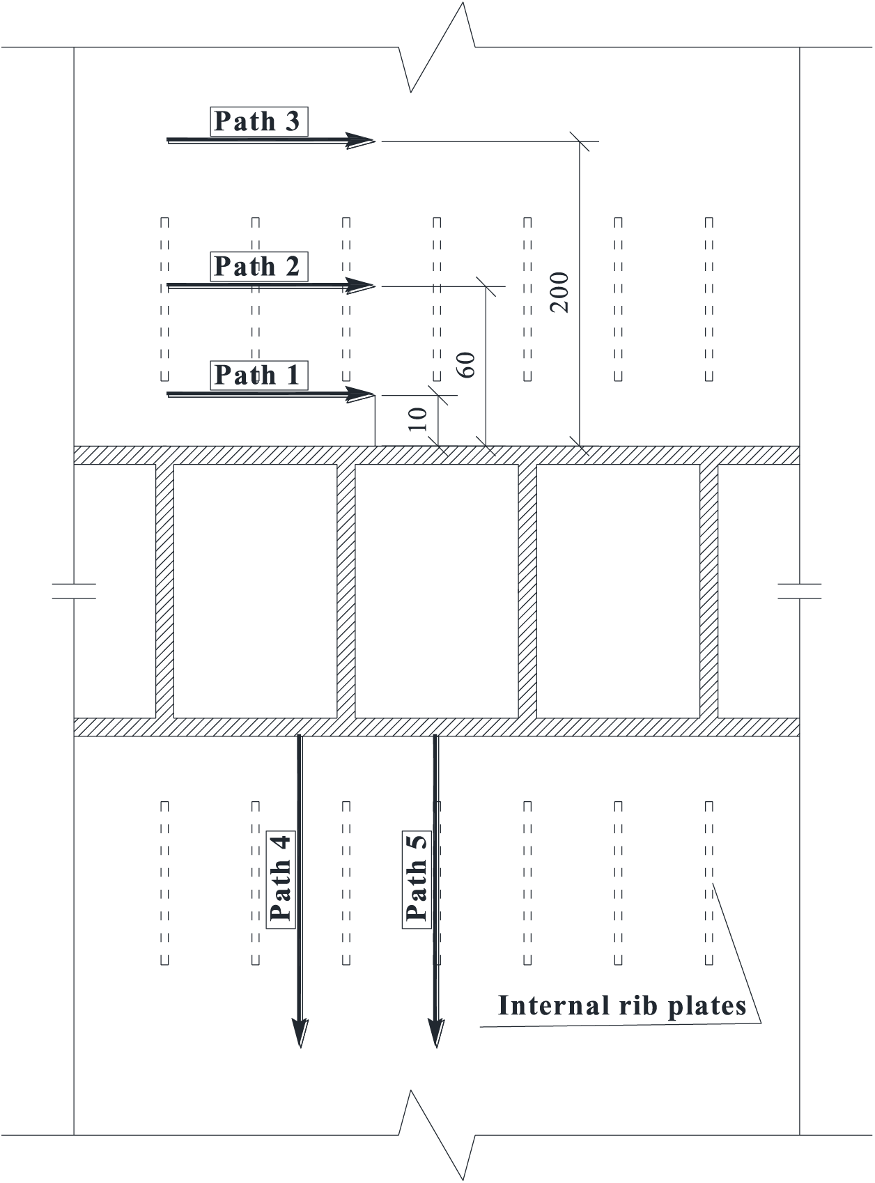
Figure 13: Schematic diagram of stress path (unit: mm)
The axial and circumferential WRS distributions of Paths 1~3 are plotted as shown in Figs. 14 and 15. From Fig. 14, the distributions of axial WRS are mainly manifested as tensile stress in Path 1 and Path 2, which will fluctuate greatly under the influence of the rib plate and the stress is larger at the rib plate; as Path 3 is farther away from the rib plate, which is less influenced by the rib plate and has smaller fluctuation of stress. Specifically, the average WRS of Path 1 is 89 MPa, and the maximum is approximately 143 MPa; the average WRS of Path 2 is 164 MPa; the average WRS of Path 3 is 94 MPa.
Figure 14: Distribution of axial WRS along the circumferential direction
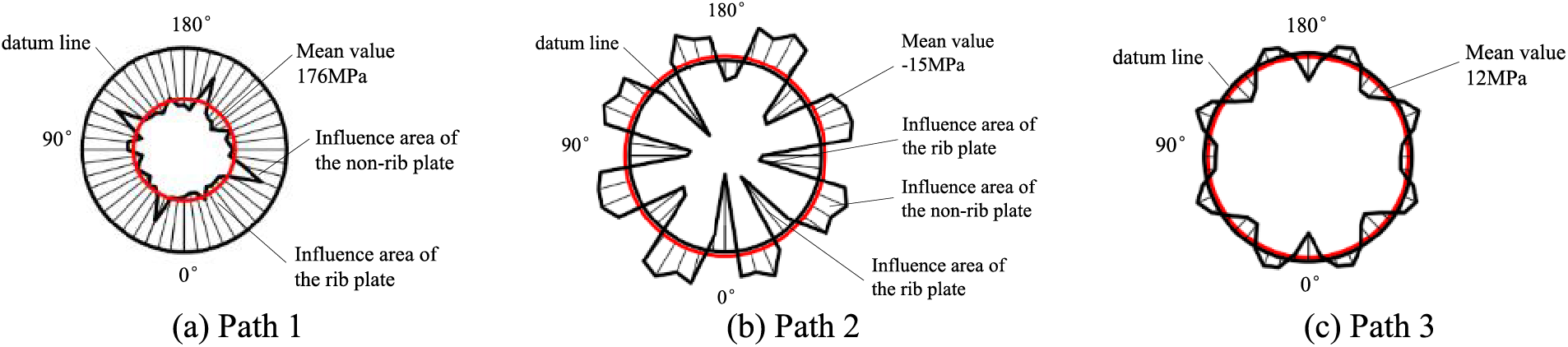
Figure 15: Distribution of circumferential WRS along the circumferential direction
As shown in Fig. 15, the distribution of circumferential WRS is mainly manifested as follows: Path 1 and Path 3 are less affected by the rib plates, and Path 2 is more affected by the rib plates. Path 2 and Path 3 manifested as tensile stress under the effect of the rib plate and compressive stress under the influence of the non-rib plate.
The distribution curves of WRS along Path 4 and Path 5 are shown in Fig. 16. The axial WRS is affected by the rib plate along the direction perpendicular to Path 4 and Path 5, showing the law of increasing first and then decreasing, and finally stabilizing. The circumferential WRS increases first and then decreases under the influence of the rib plates, increases again, and finally approaches zero. Overall, the stress values in the Path 5 direction of the rib plate area are greater than those of the non-rib plate area. It can be seen that under the influence of the rib plates, the distribution of WRS of the arch rib is more complicated. From Fig. 16, it can be observed that when the distance from the weld is 800 mm, the WRS is gentle and close to zero in both paths. Therefore, the effect scope of WRS is approximately 800 mm from the weld seam.
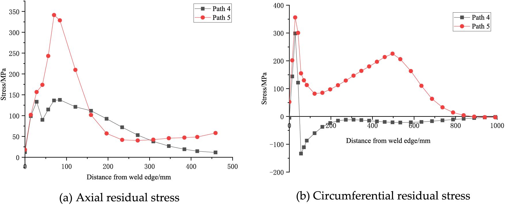
Figure 16: Layout of measuring points for deformation
4 Influence of WRS on the Mechanical Properties of the Joint
After clarifying the distribution pattern of WRS in the large-scale weld seam at the arch rib splicing joints, the WRS is introduced into the mechanical performance analysis of joints and overall structure, and its influence on the joints and the overall structure can be investigated.
4.1 Axial Deformation of the Joint
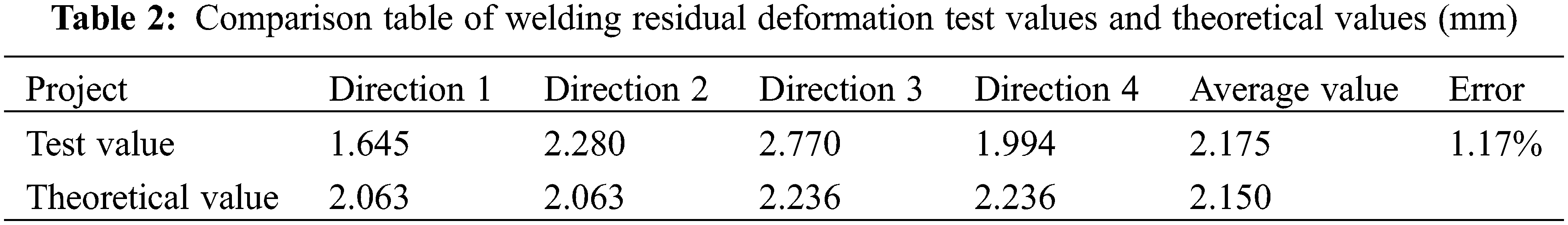
Welding residual deformation and residual stress are accompanied. The plastic deformation generated in the weld heat-affected zone will not only cause the positioning errors of the arch rib members, but also reduce the stability of the members. The residual deformation of the splicing joint along the four directions measured during the test and the corresponding deformation values obtained by the numerical model analysis are shown in Table 2. This indicates that the test values agree well with the numerical calculation results. The deformation of the arch rib along the axial direction is mainly shrinkage deformation, with a deformation value of about 2 mm.
4.2 Force Performance of the Joint
After the welding thermal analysis of the refined numerical model is completed, the SOLID70 element is converted to the SOLID185 element to analyze the mechanical properties of the joint. The geometric and material nonlinearities are taken into account in the calculation in which the same analysis model as described in Section 3.2 is used. Since the arch rib bears mainly axial force, the force of the whole structure is simulated by constraining the axial, circumferential, and radial displacements of the right end face of the joint, as shown in Fig. 17, and the left end face is applied in the form of surface load. The axial load of 100,000 kN is greater than the ultimate bearing capacity. The influence of WRS and residual deformation on the joint were investigated by comparing the following two conditions:
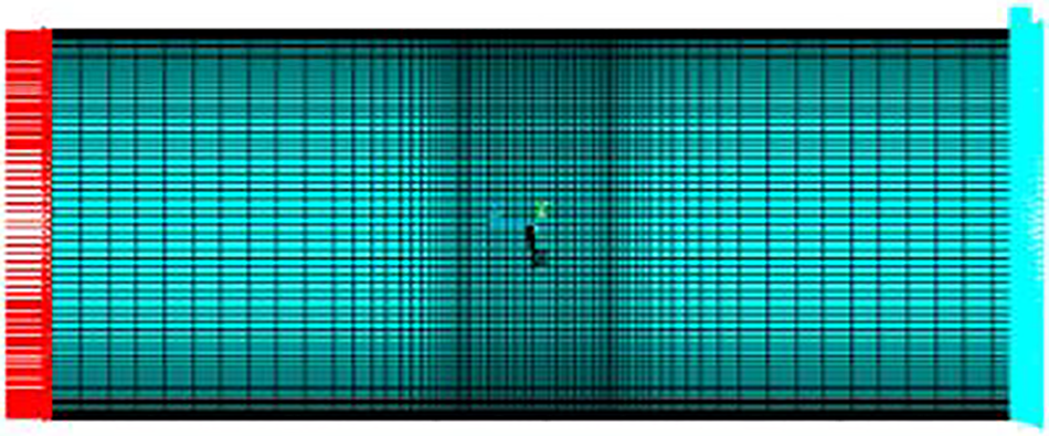
Figure 17: Finite element model
① Working condition 1, considering the influence of welding, the results of welding thermal analysis are applied to the structural model as loads.
② Working condition 2, without considering the influence of welding.
Load-displacement curves were extracted for both conditions, as shown in Fig. 18.
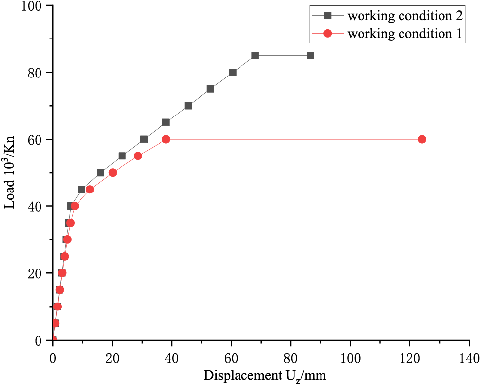
Figure 18: Load-displacement curve
From Fig. 18, it is found that the load-displacement curves of the two working conditions largely coincide when the load is small. However, as the load approaches the yield point, working condition 1 enters the plastic stage earlier and reaches the ultimate bearing capacity at a load of 60,000 kN. In contrast, in working condition 2, the joint reaches the ultimate bearing capacity at a load of 85,000 kN. The ultimate bearing capacity of working condition 1 is reduced by 29.4% compared to working condition 2.
To further analyze the influence of WRS on the axial stiffness of the joint, the average axial displacement (u) of each joint on the loading side during the loading process is extracted. Based on Eq. (4), the variation curve of the axial stiffness (K) of the joint with the average displacement (u) is plotted, as shown in Fig. 19. It finds that under the influence of WRS, the axial stiffness of the joint starts decreasing from the initial stage of loading. The initial axial stiffness decreases by approximately 4.32% compared to when WRS is not considered.
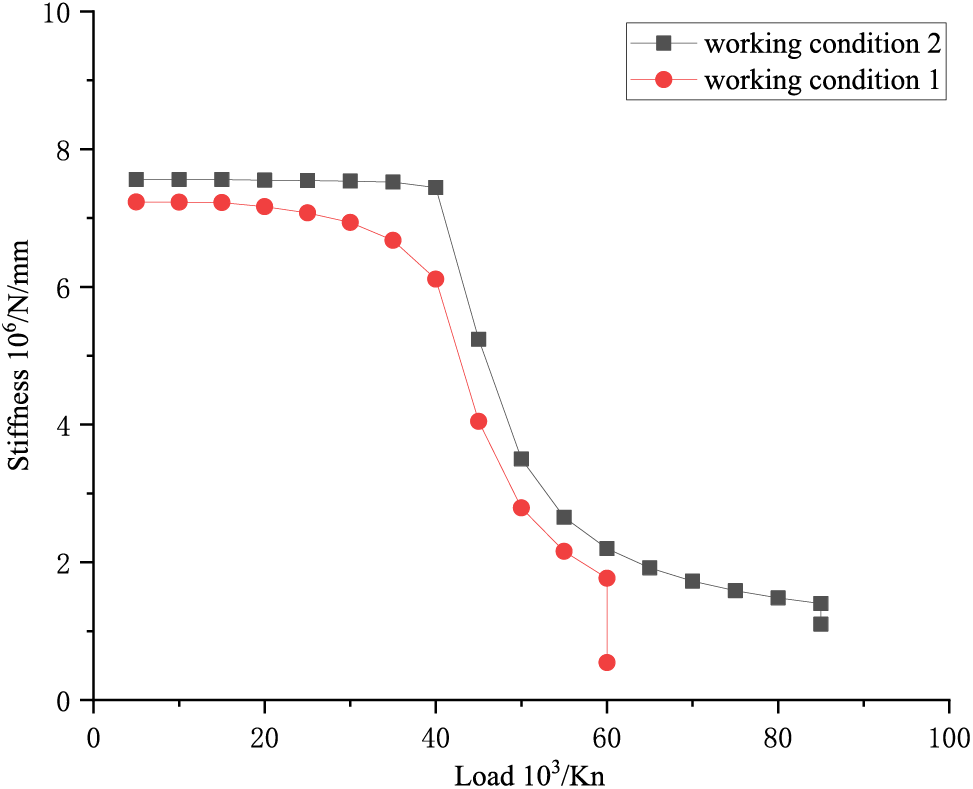
Figure 19: Axial stiffness-load curve
where F is the end axial load.
5 Influence of WRS on the Mechanical Properties of Arch Rib Structure
There is no doubt that WRS adversely affects the bearing capacity and stiffness of the joint, subsequently impacting the overall structure. A multi-scale model of the steel tube arch rib structure has been established to elucidate its specific influence on the mechanical properties of the steel tube arch rib. Meanwhile, the WRS obtained from the aforementioned analysis is introduced at the joint to analyse its effect on the overall structure.
5.1 Multi-Scale Model and WRS Simulation Method
5.1.1 Establishment of Multi-Scale Model
Considering the large span and numerous members of the structure, in order to save the calculation cost, the 1/4 space finite element model of the steel tube arch rib is established according to the symmetry of the whole bridge, as shown in Fig. 20. Guangxi Pingnan Third Bridge is assembled by two arch ribs. In this paper, the 1/2 model of the single-arch rib is selected for analysis.
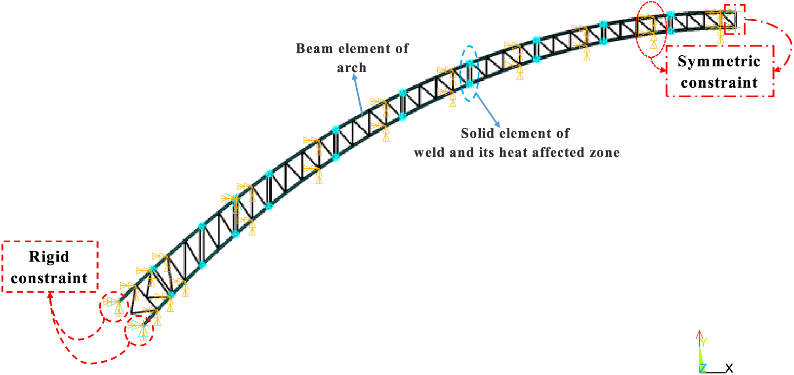
Figure 20: Finite element model of the arch rib structure
Since the WRS is mainly distributed in the weld seams and its vicinity, their distribution range is small relative to the structure as a whole. Therefore, to improve the efficiency of computation, a multi-scale numerical model of the structure is established, as shown in Fig. 21. The main body of the steel tube arch rib is modelled by BEAM188 element, the arch ribs at the splicing joints within 800 mm from both sides of the weld edge and welds are simulated by SOLID 185 solid element, and the beam element and the solid element are connected with the TARGE170 contact element and CONTA175 target element binding, the model is divided into a total of 9879 elements, including 199 beam elements, 7680 solid elements, and 1940 contact elements.
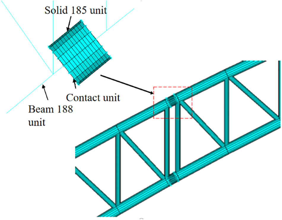
Figure 21: Schematic diagram of unit connection at different levels
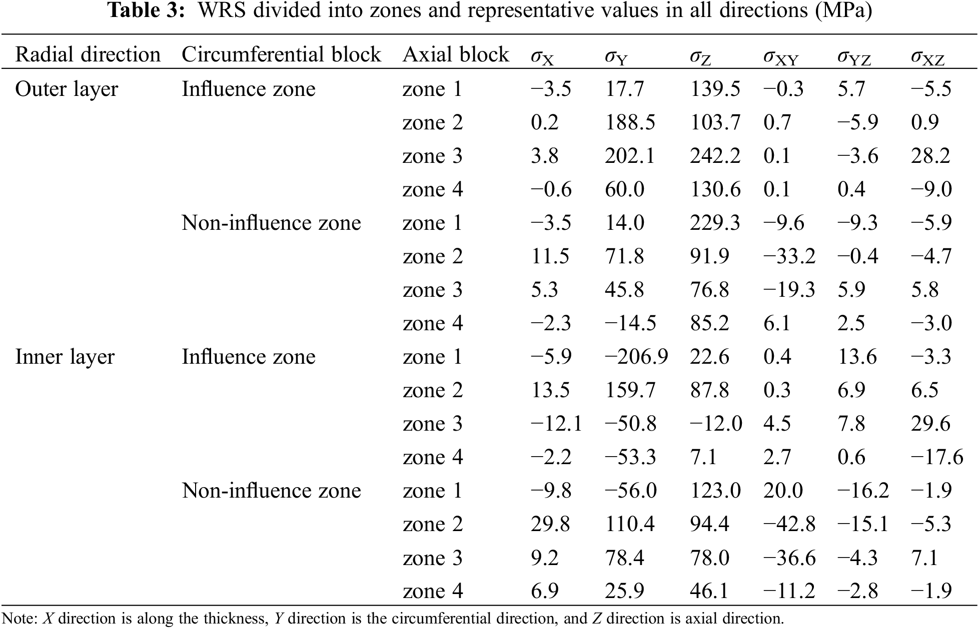
The above analysis shows that the WRS at the arch rib splicing joint is different along the axial, circumferential and radial directions of the steel tube. Therefore, when the WRS is applied, it is divided into four zones along the axial direction of the steel tube. As shown in Fig. 22, according to the influence of the rib plate, it is divided into the influence zone and non-influence zone with rib plate every 45° along the circumferential direction of the steel tube, and it is divided into the inner and outer layers along the thickness direction (radial direction) of the steel tube. The stress in each direction of each zone is extracted respectively, and the average stress of all elements in the zone is applied to the above multi-scale model as the initial WRS. The representative values of stress in each zone are shown in Table 3.
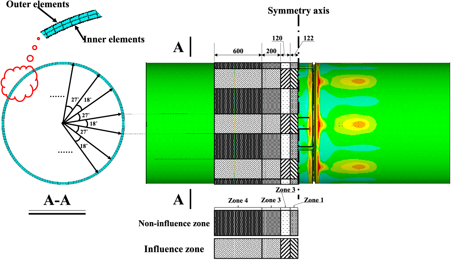
Figure 22: Zone dividing in all directions
5.2 Influence of WRS on the Mechanical Properties of Steel Tube Arch Rib
In the hoisting process of arch rib, it mainly bears the influence of its own gravity. It is assumed that in working condition 1, the steel tube arch rib is only subjected to gravity load, and in condition 2 the rib is the combined effect of structural self-weight and WRS. By comparing the calculation results of working conditions 1 and 2, the influence of WRS on the mechanical properties of the arch rib structure can be obtained. The result is illustrated in Fig. 23.
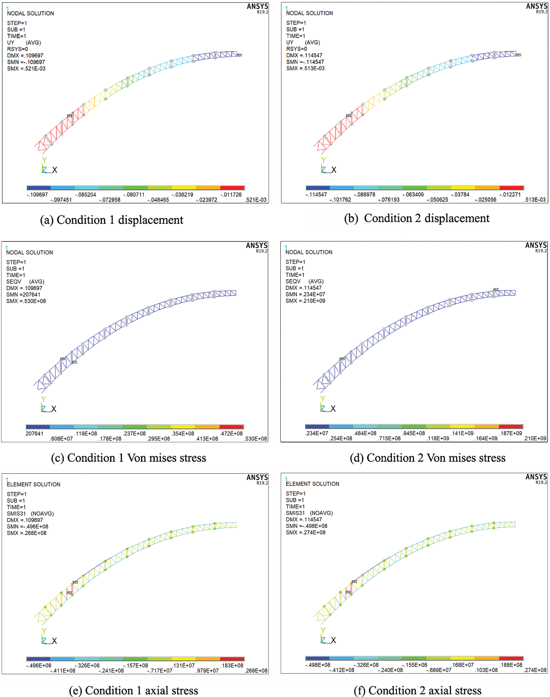
Figure 23: Deformation and stress cloud map of steel tube arch ribs under different working conditions
From Fig. 23a,c, when the steel tube arch rib is only subjected to gravity, the arch rib is deformed by overall downward deflection. The maximum deformation of the entire arch occurs at the mid-span, with a maximum vertical deformation of 0.109 m. In the direction of the transition from the mid-span to the arch supports, the joint deformation decreases in a step-like shape. Under the action of gravity, the maximum stress of the entire arch is close to the arch support, and the maximum Von Mises stress is 53 MPa, which is relatively small.
From Fig. 23b,d, when the initial WRS of the butt weld of the arch rib is considered, the deformation distribution law of the arch rib is basically the same as that of working condition 1. However, under the action of WRS, the deformation of the whole bridge slightly increases, with the maximum vertical deformation value of 0.115 m, which is 4.7% higher than condition 1. For the arch rib stress, because the WRS level is greater than the stress level caused by the self-weight of the structure, the stress cannot be directly compared, but the maximum Von Mises stress under the effect of WRS appears at the vault position. The reason for this is that the initial WRS is mainly tensile stress, and the gravity effect will reduce the tensile stress effect. The maximum stress appears at the vault position with less influence of gravity, which is within the yield strength.
From Fig. 23e,f, the beam element is mainly subjected to compressive stress under both working conditions after removing the solid elements with applied WRS, with the maximum value appearing at the same position, at 49.6 MPa under condition 1 and 49.8 MPa under condition 2.
The mechanical properties of both the steel tube arch rib splicing joint and the overall structure of the Guangxi Pingnan Third Bridge, the world’s largest span concrete-filled steel tube arch bridge, were analyzed in this paper to assess the influence of WRS. The following conclusions are obtained:
1) The distribution of WRS in the arch rib is greatly influenced by the rib plate. The axial WRS in the heat-affected zone are primarily tensile, and they alternate between increasing and decreasing along the circumferential direction of the main tube, while they first increase and then decrease along the axial direction and finally tend to stabilize. On the other hand, the circumferential WRS are distributed in an alternating pattern of tensile and compressive stresses along the circumferential direction of the main tube, and they tend to approach zero along the axial direction and follow a pattern of increasing and then decreasing.
2) WRS have a remarkable effect on the ultimate bearing capacity of joints, resulting in a reduction of approximately 29.4%. Additionally, the WRS also decrease the joint stiffness, with the initial axial stiffness experiencing a reduction of around 4.32%.
3) The WRS during the hoisting stage leads to an increase in the vertical deformation of the steel tube arch rib by approximately 4.7%. However, it has a lesser influence on the internal force of the arch rib members.
Acknowledgement: Thank you to all the workers who have provided support for conducting this experiment.
Funding Statement: This research was funded by the Science and Technology Research Program of the Chongqing Municipal Education Commission (grant number KJQN202403002).
Author Contributions: The authors confirm contribution to the paper as follows: study conception and design: Chunling Yan, Renzhang Yan; experimental and numerical simulation: Chunling Yan, Zhenxiu Zhan, Xiyang Chen, Yu Han; data processing: Chunling Yan, Zhenxiu Zhan, Xiyang Chen; analysis of results: Chunling Yan, Renzhang Yan, Xiyang Chen; draft manuscript preparation: Chunling Yan, Zhenxiu Zhan. All authors reviewed the results and approved the final version of the manuscript.
Availability of Data and Materials: The data that support the findings of this study are available from the corresponding author upon reasonable request.
Ethics Approval: Not applicable.
Conflicts of Interest: The authors declare no conflicts of interest to report regarding the present study.
References
1. Farajian M. Welding residual stress behavior under mechanical loading. Weld World. 2013;57(2):157–69. doi:10.1007/s40194-013-0024-8. [Google Scholar] [CrossRef]
2. Yan LZ. Influences of welding residual stresses on performance of steel structures and methods for their elimination. Adv Mater Res. 2014;3255(971–973):889–92. doi:10.4028/www.scientific.net/AMR.971-973.889. [Google Scholar] [CrossRef]
3. Nassiraei H, Rezadoost P. SCFs in tubular X-joints retrofitted with FRP under out-of-plane bending moment. Mar Struct. 2021;79(6):103010. doi:10.1016/j.marstruc.2021.103010. [Google Scholar] [CrossRef]
4. Hossein N, Pooya R. Stress concentration factors in tubular T-joints reinforced with external ring under in-plane bending moment. Ocean Eng. 2022;266(17–18):112551. doi:10.1016/j.oceaneng.2022.112551. [Google Scholar] [CrossRef]
5. Jiamin S, Thomas N, Klaus D. Generation and distribution mechanism of welding-induced residual stresses. J Mater Res Technol. 2023;27:3936–54. doi:10.1016/j.jmrt.2023.10.252. [Google Scholar] [CrossRef]
6. Acevedo C, Nussbaumer A. Effect of tensile residual stresses on fatigue crack growth and S-N curves in tubular joints loaded in compression. Int J Fatigue. 2011;36(1):171–80. doi:10.1016/j.ijfatigue.2011.07.013. [Google Scholar] [CrossRef]
7. Acevedo C, Evans A, Nussbaumer A. Neutron diffraction investigations on residual stresses contributing to the fatigue crack growth in ferritic steel tubular bridges. Int J Press Vessels Pip. 2012;95(17):31–8. doi:10.1016/j.ijpvp.2012.05.004. [Google Scholar] [CrossRef]
8. Acevedo C, Drezet JM, Nussbaumer A. Numerical modelling and experimental investigation on welding residual stresses in large-scale tubular K-joints. Fatigue Fract Eng Mater Struct. 2013;36(2):177–85. doi:10.1111/j.1460-2695.2012.01712.x. [Google Scholar] [CrossRef]
9. Huang YH, Wang RH, Zhang SB, Chen GM, Fu JY, Wang TQ. Experimental study on the welding residual stresses of integral joint using full-scale joint model of a steel truss bridge. Adv Struct Eng. 2013;16(10):1719–27. doi:10.1260/1369-4332.16.10.1719. [Google Scholar] [CrossRef]
10. Liu J, Zhang CR, Qu LW, Jiang L. Study on distributed properties of welding residual stress in bridge nodes. Appl Mech Mater. 2014;2974(501–504):1166–9. doi:10.4028/www.scientific.net/AMM.501-504.1166. [Google Scholar] [CrossRef]
11. Klassen J, Friedrich N, Fricke W, Nitschke-Pagel T, Dilger K. Influence of residual stresses on fatigue strength of large-scale welded assembly joints. Weld World. 2017;61(2):361–74. doi:10.1007/s40194-016-0407-8. [Google Scholar] [CrossRef]
12. Cui C, Zhang QH, Luo Y, Hao H, Li J. Fatigue reliability evaluation of deck-to-rib welded joints in OSD considering stochastic traffic load and welding residual stress. Int J Fatigue. 2018;111(9):151–60. doi:10.1016/j.ijfatigue.2018.02.021. [Google Scholar] [CrossRef]
13. Cui C, Zhang QH, Bao Y, Bu YZ, Ye ZT. Fatigue damage evaluation of orthotropic steel deck considering weld residual stress relaxation based on continuum damage mechanics. J Bridge Eng. 2018;23(10):4018073. doi:10.1061/(ASCE)BE.1943-5592.0001280. [Google Scholar] [CrossRef]
14. Puymbroeck VE, Nagy W, Backer DH. Influence of the welding process on the residual welding stresses in an orthotropic steel bridge deck. Pro Struct Integ. 2018;13:920–5. doi:10.1016/j.prostr.2018.12.173. [Google Scholar] [CrossRef]
15. Lee JH, Jang BS, Kim HJ, Shim SH, Im SW. The effect of weld residual stress on fracture toughness at the intersection of two welding lines of offshore tubular structure. Mar Struct. 2020;71(1):102708. doi:10.1016/j.marstruc.2020.102708. [Google Scholar] [CrossRef]
16. Jin D, Hou C, Shen LM. Effect of welding residual stress on the performance of CFST tubular joints. J Construct Steel Res. 2021;184(1):106827. doi:10.1016/j.jcsr.2021.106827. [Google Scholar] [CrossRef]
17. Chen SH, Chi MZ, Fu XM, Mao JW, Ju JS. Stability analysis of H-section steel arch considering effect of welding residual stress. J Phys Conf Series. 2021;1777(1):012035. doi:10.1088/1742-6596/1777/1/012035. [Google Scholar] [CrossRef]
18. Wei J, Peng Z, Kui L. Investigation of welding temperature field and residual stresses of corrugated steel web girders. Structures. 2022;44:1416–28. doi:10.1016/j.istruc.2022.08.047. [Google Scholar] [CrossRef]
19. Yan LJ, Guan YP, Luo K, Wang QC. Corrugated steel web I-girder welding deformation and residual stress research. Structures. 2023;58(1):105602. doi:10.1016/j.istruc.2023.105602. [Google Scholar] [CrossRef]
20. Lu WL, Sun JL, Su H, Gao C, Zhang XB. Experimental research of welding residual stress of butt welded joint of thick steel plate. Metals. 2023;13(1):120. doi:10.3390/met13010120. [Google Scholar] [CrossRef]
21. Yan RZ, Zhang CL, Wang S, Liu JQ, Sun T. Distribution of residual stress in the sphere-pipe connection welds of welded hollow spherical joints. Adv Steel Constr. 2023;19(3):262–72. [Google Scholar]
22. Yan RZ, Yu ZY, Wang S, Liu JQ. Influence of welding residual stress on bending resistance of hollow spherical joints. J Construct Steel Res. 2023;208:108004. [Google Scholar]
23. Luo JY, Tan C, Li X, Tang YH. Influence of welding residual stress and welding method on fracture properties of welded joints. Proce Instit Mech Eng Part C: J. Mech Eng Sci. 2024;238(5):1629–41. [Google Scholar]
24. Han Y, Yan RZ, Chen XY, Luo XB, Qin DY. Welding residual stress analysis of large-scale steel tube arch rib splicing weld under load. Bridge Constr. 2022;52(4):74–81 (In Chinese) [Google Scholar]
25. Liu XH, Guo CQ. The influence of blind-hole depth and bore to strain energy relief coefficients-a case study. Adv Mater Res. 2012;479:1993–6. [Google Scholar]
26. Banik SD, Kumar S, Singh PK, Bhattacharya S, Mahapatra MM. Distortion and residual stresses in thick plate weld joint of austenitic stainless steel: experiments and analysis. J Mater Process Technol. 2021;289:116944. [Google Scholar]
27. Teng TL, Lin CC. Effect of welding conditions on residual stress due to butt welds. Int J Pres Ves Pip. 1998;75(12):857–64. doi:10.1016/S0308-0161(98)00084-2. [Google Scholar] [CrossRef]
28. Deng D, Murayama H. Prediction of welding distortion and residual stress in a thin plate butt-welded joint. Comp Mater Sci. 2008;43(2):353–65. doi:10.1016/j.commatsci.2007.12.006. [Google Scholar] [CrossRef]
29. Chen JQ, Xiao SH, Wu G, Yang XY. Comparison of heat source models in numerical simulation of welding process. Welding Tech. 2006;35(1):9–11+4 (In Chinese) [Google Scholar]
30. Chen XY. Experimental study on welding residual stress of large-scale steel tube arch ribs under load (Master Thesis). Chongqing Jiaotong University: Chongqing, China; 2021 (In Chinese). [Google Scholar]
Cite This Article
 Copyright © 2025 The Author(s). Published by Tech Science Press.
This work is licensed under a Creative Commons Attribution 4.0 International License , which permits unrestricted use, distribution, and reproduction in any medium, provided the original work is properly cited.
 Downloads
 Citation Tools