
 Submit a Paper
 Propose a Special lssue
 Open Access
ARTICLE

Optimization of Structure and Mechanical Performance Analysis of Double-Layer Hole Oil Boom in Rapid River Channels
1 Petroleum Engineering School, Southwest Petroleum University, Chengdu, 610000, China
2 Development and Reform Bureau of Longmatan District, Luzhou, 646000, China
3 National Pipe Network Group Southwest Pipeline Co., Ltd., Chengdu, 610623, China
* Corresponding Author: Kai Zhang. Email:
Structural Durability & Health Monitoring 2025, 19(4), 937-952. https://doi.org/10.32604/sdhm.2025.063177
Received 07 January 2025; Accepted 21 February 2025; Issue published 30 June 2025
 View Full Text
 Download PDF
Abstract
In order to reduce the ecological environmental pollution and economic losses caused by oil spill accidents from cross-river oil pipelines, this paper studies the structures of oil containment booms used for intercepting oil spills in rapid rivers and proposes a new type of double-layer hole oil containment boom. By establishing a solid mechanics model, the geometric deformation and stress-strain distribution patterns of the double-layer hole oil containment boom under rapid flow velocities were analyzed. Additionally, the impact of the skirt angle, hole size, and porosity on the mechanical properties of the new oil containment boom structure was investigated, and the optimization range of the boom structure was determined. The results showed that, compared to the traditional single-layer oil containment boom, the optimized new boom reduced maximum tensile deformation by 91.1% and the maximum equivalent stress by 45.3%. The research findings provide an effective reference for the rational design of oil containment booms in rapid rivers to ensure the safety of energy transportation and protect the ecological environment.Keywords
The demand for oil and gas in national life and production has been increasing year by year, and the frequent transportation of energy has led to a corresponding rise in the frequency of oil spill accidents in various waters [1–3]. On 26 July 2010, an oil pipeline operated by Canada’s Enbridge company ruptured in Michigan, releasing at least 4000 cubic meters of crude oil into the Kalamazoo River [4]. On 10 November 2012, a circumferential weld seam cracked at an oil transfer station of the China National Petroleum Corporation, resulting in approximately 200 cubic meters of crude oil leakage [5]. In 2021, the vessel “Symphony” was involved in an oil spill accident in China’s Yellow Sea, severely affecting a 10-nautical-mile radius [6]. Once oil spills into a watershed, it can cause significant economic losses and potentially pollute the environment, as well as pose risks such as fire and explosions [7–9].
As a key piece of equipment for emergency handling of oil spills on water, oil containment booms play a role in preventing oil spill dispersion and assisting in oil recovery [10–12]. To prevent further deterioration of the situation, many scholars have conducted research on the improvement of containment boom devices and their adaptability in rapid flow river channels. Feng et al. [13] proposed that oil containment booms can be classified according to their structure into categories such as single-skirt, double-skirt, L-shaped, sloped, mesh, and screen types. Hou et al. [14] designed a close-proximity ship oil containment boom for the emergency containment of oil spills near ships. They used FLUENT software to simulate and analyze the failure of the boom under different parameters. Wang et al. [15] developed a miniature oil containment boom that enhances oil blocking effectiveness by utilizing a fine copper mesh on the surface to adsorb oil spills. Wei et al. [16] optimized oil containment booms by focusing on indicators such as reducing the speed of oil containment failure and increasing cumulative oil containment failure time, considering factors like skirt shape and angle. Xing et al. [17] studied the interaction between water and oil barriers by establishing a two-dimensional multiphase model and analyzed the effects of different skirt lengths, buoyancy-to-weight ratios, and strut shapes on the containment performance of floating arms. Liu et al. [18] established a numerical simulation model based on the smoothed particle hydrodynamics (SPH) method and found that the oil containment capability of oil booms is related to the height ratio of the upper and lower skirts and the type of skirt angle. The greater the proportion of the upper skirt height, the better the oil retention performance of the boom. Pei et al. [19] proposed a coupled numerical method combining smoothed particle hydrodynamics (SPH) and element bending group (EBG) methods to study the control of oil spills using flexible oil booms. This approach addresses complex issues involved in controlling oil spills with flexible booms, such as free surface flows, multiphase flows, and fluid-structure interactions.
Regarding the study of oil boom performance in fast-flowing river channels, Felix et al. [20] studied the flow behavior of heavy fuel oil after leakage through a simplified CFD model, revealing the influence of oil density, viscosity, and water flow conditions on the suspension and horizontal movement of oil plumes in turbulent environments. This provides important reference for the design and optimization of oil containment booms in turbulent river channels. Dhaka et al. [21] proposed that ocean waves and water currents exert torque on the impermeable barriers of the skirt below the water surface, causing the boom skirts to rotate. Therefore, oil booms should have sufficient flexibility and rigidity to follow wave movements and still retain as much oil as possible. Hou et al. [22] established a multiphase flow analysis model to simulate the oil level around the oil boom and used numerical methods to analyze the impact of various working conditions on the oil containment effectiveness. The study concluded that an increase in water flow velocity causes the oil layer thickness to increase linearly and forms high-speed zones and vortices near the boom, accelerating the failure of the containment system. Yang et al. [23] used FLOW3D software to simulate the oil spill containment process of oil booms under wave and current influence. They discovered that modifying the shape structure at the bottom of the boom’s skirts can effectively improve the oil retention performance, providing insights for the optimization of oil boom design. Hou et al. [24] combined experiments and simulations to explore the impact of factors such as skirt height and wave-current interaction on the effectiveness of oil booms and the reasons for oil containment failure. The study showed that as the skirt depth increases, the oil containment effectiveness of the boom continually improves, and the amount of oil loss after containment failure decreases with greater skirt height. Additionally, oil containment is more favorable under conditions where waves and currents are in opposing directions. Zhao et al. [25] designed a oil containment boom for use at sea. Through software simulation, they found that under the condition of a constant total pore area on the skirt of the boom, the more perforations there are and the smaller the pore diameter, the better the boom’s resistance to flow. Xing et al. [26] established a three-phase numerical model and compared it with experiments to study the response of oil droplets to wave current hybrid conditions. The results showed that when the flow velocity increased from 0.06 to 0.66 m/s, oil accumulated on the offshore side of the oil containment boom, and the drainage failure occurred after the velocity reached 0.48 m/s. Hao et al. [27] combined the standard k-epsilon model with the VOF multiphase flow model to study the impact of different towing speeds on oil boom gates and analyzed the flow field morphology under towing conditions. The study found that when the towing speed reaches 0.7 m/s, a single oil boom becomes ineffective, whereas a double oil boom still functions well at this speed. Fang et al. [28] revealed the stability challenges of oil slick containment by a single boom through experimental and theoretical analyses. They found that water current velocity, oil slick thickness, and wave effects could lead to oil escape or boom failure. Notably, under conditions of thin oil slicks and high current velocities, containment efficiency was significantly lower than theoretical predictions, with the critical velocity deviation of theoretical models falling within a 10% error margin. Hossein Babaei et al. [29] analyzed the oil containment performance of oil spill booms under high-speed conditions through two-dimensional numerical simulations and flume experiments, revealing a significant decline in efficiency under high flow velocities and complex wave conditions. It highlighted the gap between theoretical limits and practical performance, providing a reference for oil boom design.
Although many scholars have studied the optimal design of oil containment booms, current research mainly focuses on intercepting oil spills in calm waters, such as oceans, emphasizing the impact of waves and currents on the stability of the booms. However, there is limited research on the optimal design of oil booms under the impact of high flow velocities in fast-flowing rivers. “Fast flow” refers to flow in an open channel where the flow velocity exceeds the wave speed, preventing disturbance waves caused by external obstacles from moving upstream. In the field of hydraulics, its flow velocity has not yet been clearly defined. According to China’s national standard GB/T 34621-2017 [30], a water body with wave heights of 0–0.3 m and flow velocities ≥0.4 m/s is defined as a calm fast-flowing water area. Taking the Nu River in China as an example, which is a typical representative of pipeline crossings over fast-flowing rivers in China, its flow velocity does not exceed 1.5 m/s during the dry season, and the average flow velocity is 2.5 m/s during the wet season. Since flow velocity is the main factor affecting the forces on oil booms [31,32], this article selects 1.5 m/s as the typical flow velocity for “fast-flow” type rivers, as this velocity is significantly representative for fast-flowing rivers.
Currently, the most commonly used type of oil containment boom in engineering is the solid float boom, with the PVC900 model often employed in high flow velocity and large wave conditions. The specific size parameters are shown in Table 1. Arranging a double layer of oil containment booms can enhance oil containment efficiency and reduce the consequences of oil spills due to the failure of single-layer booms in fast-flowing conditions. The working principle of the double-layer boom is illustrated in Fig. 1: when an oil spill surpasses the first boom, due to the smaller pressure behind it, vortices form in this area. At this point, a second boom is used to block the oil-water mixture in the vortex zone. Based on the traditional PVC900 oil containment boom model and its size parameters, this study proposes a double-layer hole oil containment boom, as shown in Fig. 2, with its size parameters listed in Table 1. The new boom is composed of a float, skirt, hole, and fixing devices. Traditional booms face significant increases in stress and strain under fast-flow conditions due to their large underwater force-bearing area, so holes are introduced to reduce the load on the boom. Previous research [33] found that, under identical simulation conditions, the double-layer hole oil containment boom possesses a greater oil storage capacity at peak interception times. Furthermore, the maximum oil interception capacity of the new oil boom exceeds that of traditional booms, enhancing the maximum oil interception capacity and delaying peak interception times. The skirt of the new boom is designed as a double layer with a fixed angle α between the layers. The total height of the skirt is H, divided into two parts from top to bottom: the upper part is a solid skirt with a height of H0, primarily for isolating oil spills; the lower part is a hole skirt with hole openings, with a hole height of Hk = H1 + H2, designed to reduce the impact of water flow.
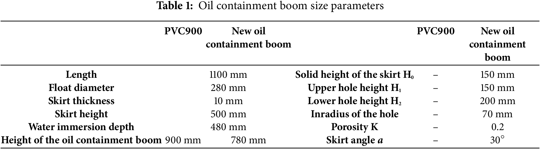
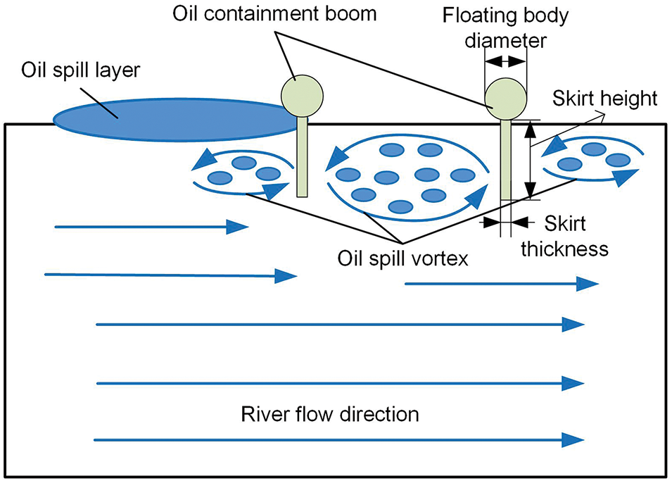
Figure 1: Diagram of double layer of oil containment booms
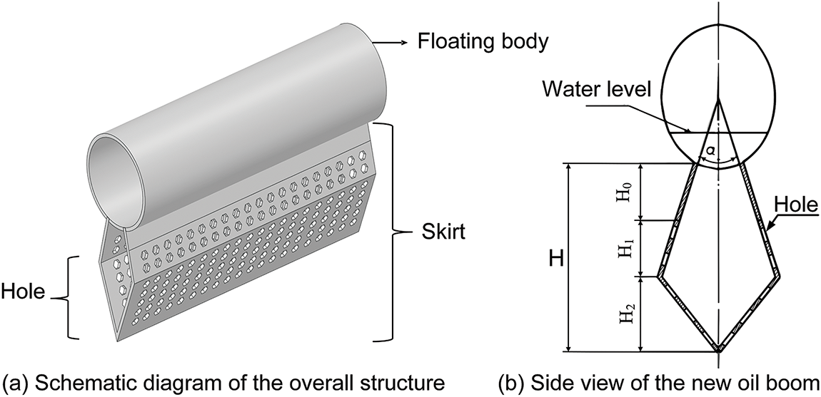
Figure 2: Diagram of the structure of a new type of oil containment boom
This study analyzes the feasibility of double-layer hole oil containment booms in fast-flowing rivers from the perspective of mechanical performance and optimizes their structural parameters, while also conducting a comparative analysis with traditional booms. The research aims to provide an effective reference for the design of oil containment booms and oil spill environmental protection, addressing the gap in research on boom design in rapid rivers.
2 Establishment of Mechanical Model
The floating body provides buoyancy for the oil containment boom, and it is long and cylindrical, using EPE pearl cotton as the floating body material, wrapped with PVC fabric. The skirt is the primary underwater structure of the oil containment boom for intercepting oil, made of multiple layers of PVC fabric, and the holes on the skirt are sewn. The oil containment boom is connected in series through sewing. The counterweight chain typically uses a steel anchor chain to adjust the draft depth of the boom and is constrained by a steel wire rope to maintain the balance of the boom in the water.
The following assumptions are made in the numerical simulation:
1. This study assumes that the oil containment boom does not deform when initially immersed in water, and minor structural deformation of the boom does not affect the fluid.
2. The flow velocity of the river is in a steady state, and there are no undulating waves.
3. The angle between the flow direction and the normal vector of the oil containment boom is zero, and there is no longitudinal or lateral displacement of the boom in the water.
This study establishes a mechanical model of a double-layer hole oil boom using ANSYS Fluent 2022 software, simplifying the effect of rapid flow on the double-layer hole oil boom into a “river-oil boom” mechanical model, as shown in Fig. 3. The middle area represents the new type of oil boom. To prevent the oil boom from having dimensions significantly larger in one direction than in others and to accurately reflect its structure, the study object in the model is a single small section of the oil boom. The fluid domain represents the river. To ensure the full development of river flow and to explore the relationship between oil boom deformation and nearby hydraulic parameters, the length (z-direction) of the fluid computational domain is 4.0 m, the width (x-direction) is 3.0 m, and the depth (y-direction) is 2.0 m. The computational domain is an open water area.
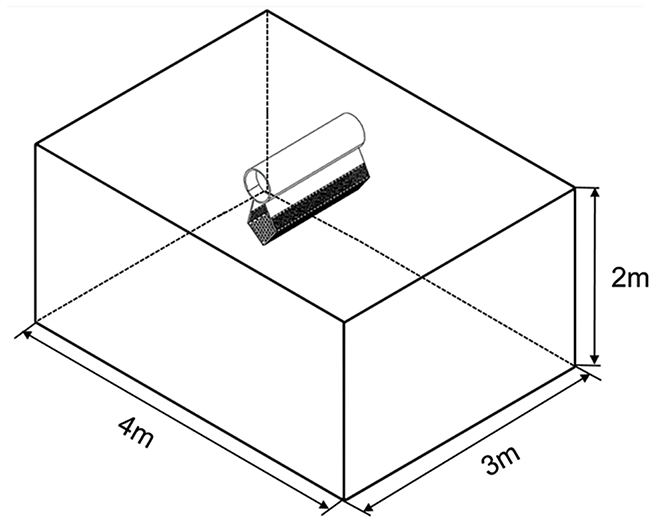
Figure 3: “River-Oil Boom” model
In the optimization design of a new type of oil boom for rapid river channels, the main focus of the study is the stress and strain caused by the force exerted by the river on the oil boom. Therefore, the method selected is a solid mechanics calculation method based on the weak coupling method [34]. This means that the results of the fluid analysis (such as forces, loads, etc.) are transferred to the solid structure for analysis, but the results of the solid structure analysis are not fed back to the flow field.
2.2 Flow Field Control Equation
In practical marine environments such as bays and rivers, fluid flow typically takes the form of turbulence. Under macroscopic conditions, water is considered incompressible, and its flow satisfies the laws of conservation of mass, momentum, and energy. The corresponding equations are shown in Formulas (1)–(3).
In the equation: K represents kinetic energy, and μe is dynamic viscosity. Velocity and density are denoted as ui and ρi, respectively. fi represents the gravitational body force acting on the fluid, h is enthalpy, and Sm and Ri are the mass source term and heat source term, respectively.
Li et al. [35] verified the accuracy of the k-ε turbulence model in dynamic fluid interface tracking by comparing numerical simulation results with the tank experiment data of Fan et al. Fan et al.’s experimental data includes oil spill trajectories, diffusion ranges, and oil film thickness. The results show that, in both stationary and flowing water bodies, the simulation results of oil spill diffusion using the k-ε model combined with the VOF method have an error of less than 15% compared to the experimental data. Additionally, the model can accurately predict the retention depth and lateral diffusion rate of the oil phase in a density-stratified environment.
In rapid flows, the response process of the oil boom exhibits fully developed turbulence. Currently, the standard k-epsilon model is the most widely used two-equation eddy viscosity model and is commonly employed for the simulation of fully turbulent flows. Therefore, the overall governing equations for the flow field are based on the standard k-epsilon turbulence model. The turbulence kinetic energy equation k:
Dissipation equation ε:
where:
In the equation: Gk represents the production term of turbulent kinetic energy k caused by the mean velocity gradient, C1ε and C2ε are empirical constants, and σk and σε are the Prandtl numbers corresponding to turbulent kinetic energy and dissipation rate, respectively. The fluid is incompressible, with empirical constants C1ε = 1.44, C2ε = 1.92, σk = 1, and σε = 1.3.
The simulation involves free surface flow, and the kinematic boundary condition of the free liquid surface is:
In the equation: F represents all physical variables on the free liquid surface.
The pressure on the free liquid surface, when surface tension is not considered, satisfies:
In the equation: Pa represents atmospheric pressure, measured in pascals (Pa).
In the boundary conditions, the river inlet uses a velocity inlet with a speed of 1.5 m/s. The river outlet uses a pressure outlet with the pressure set to atmospheric pressure. The symmetry plane along the flow direction is set as a symmetric boundary, and the contact surface between the water body and the oil boom is set as a no-slip wall.
2.4 Mesh Generation and Independence Verification
The area where the oil boom contacts the river is called the coupling surface. As a solid region, the coupling surface of the oil boom needs to completely overlap with the fluid region. Due to the large volume of the river model and the irregularity of the coupling surface, ANSYS ICEM was used to generate a tetrahedral mesh, and mesh refinement was performed in the coupling surface area where significant changes in stress and strain occur.
The focus of this study is the stress experienced by a double-layer mesh oil boom after river impact. Therefore, the independence of the maximum static pressure value on the coupling surface with respect to the number of meshes was investigated. For the four mesh models with 1.52, 3.41, 5.02, and 6.83 million meshes, the average errors of the maximum static pressure value on the coupling surface compared to the results calculated with 6.83 million meshes are 5.14%, 3.61%, and 1.81%, respectively. As the number of meshes increases, the variation in the maximum static pressure value on the coupling surface gradually decreases. To ensure that the relative difference in the maximum static pressure value on the river coupling surface is within 2%, this study chooses to use 5.02 million meshes. The mesh of the entire computational domain is shown in Fig. 4a. Fig. 4b shows the mesh on the surface of the oil containment boom, and Fig. 4c displays the surface mesh at the top of the computational domain.
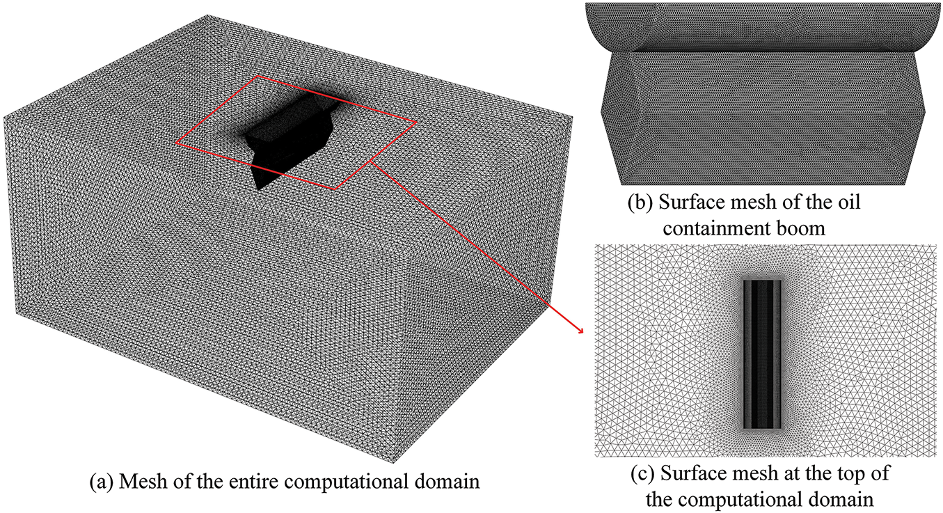
Figure 4: Model mesh diagram
2.5 Parameters Affecting Mechanical Properties
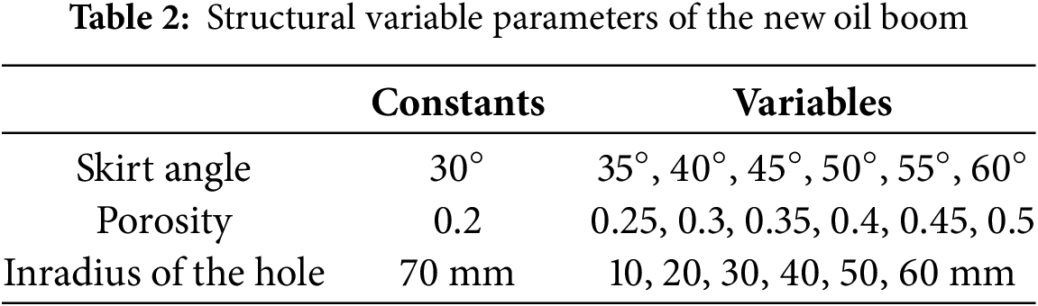
Compared to traditional oil booms, the new type of oil boom has different structural features such as the angle between skirts, porosity, and hole size. These three structural parameters may alter variables such as the angle between the oil boom and the river flow direction, the magnitude of momentum exchange between the river and the oil boom, and the flow state near the oil boom. Therefore, these three parameters affecting mechanical properties are taken as the key optimization directions. The parameters used in the initial example are shown in Table 2. The porosity calculation formula for the new oil boom filter hole is:
In the equation: K represents porosity; n is the number of holes; S0 is the area of a single hole, in mm2; S1 is the total surface area of the hole section.
To explore the optimal mechanical structure of the oil boom in rapid currents, the median value of the ‘rapid current’ velocity range is referenced, taking u = 1.5 m/s. A comparison group is designed for simulation and analysis. The parameters for setting simulation variables are shown in Table 2.
3 Optimization of Oil Boom Structure
The skirt angle determines the direction of the actual force exerted by the water on the oil containment boom. By setting fixed variables: the circumscribed circle radius R within the hole is 70 mm, the porosity K is 0.2, a comparative group simulation calculation is conducted. When the skirt angle α is 30°, 45°, and 60°, the stress-strain cloud maps are shown in Fig. 5. The variation pattern of the skirt angle and the maximum stress and strain is shown in Fig. 6.
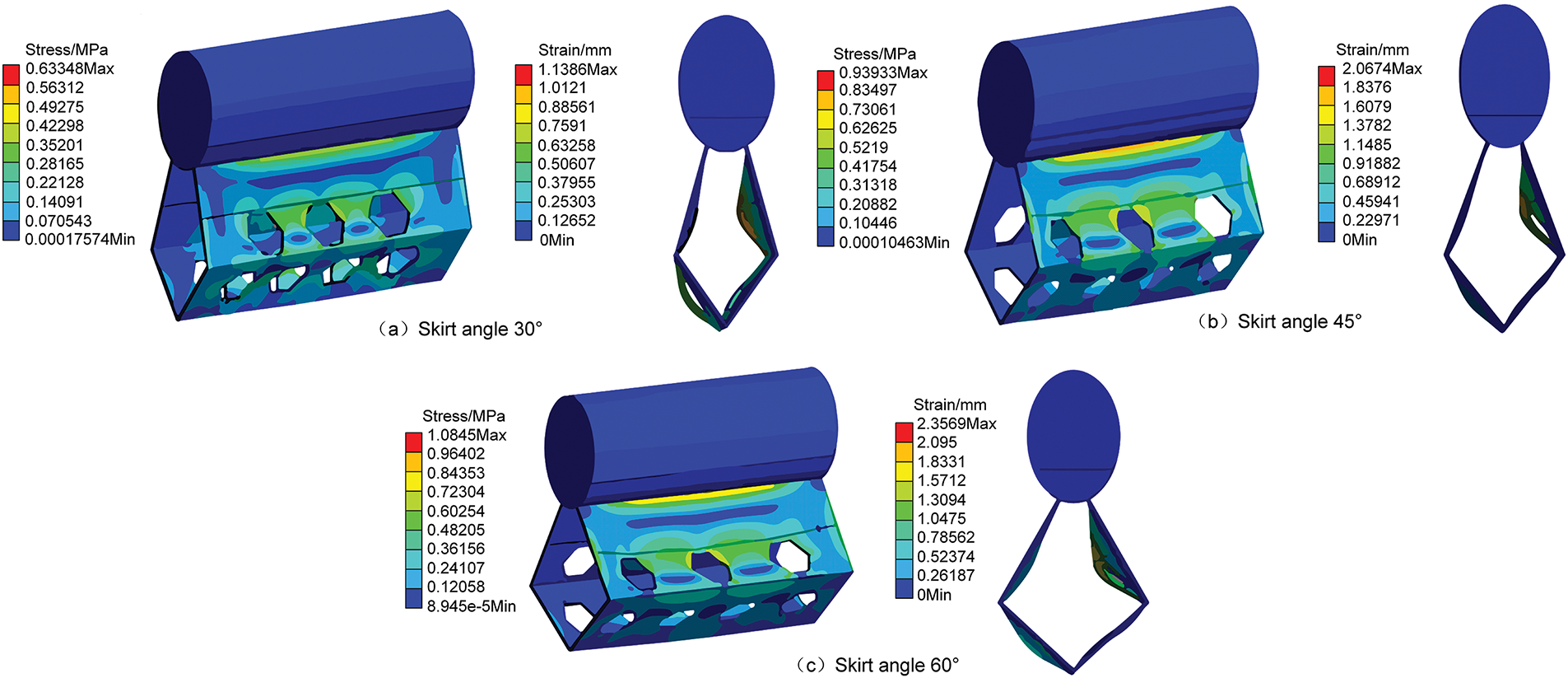
Figure 5: Stress-strain contour maps under different skirt angles
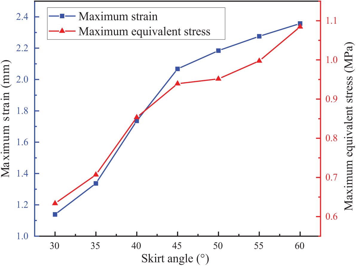
Figure 6: Relationship diagram of maximum stress and strain under different skirt angles
As shown in Fig. 5, the stress-strain distribution patterns of the three models are the same. The maximum equivalent stress is concentrated at the connection between the skirt and the floating body, and it increases with the increase of the skirt angle. This is because as the skirt angle increases, the area of the hole perpendicular to the water flow velocity direction decreases, causing the momentum of the water flow to concentrate at the connection between the skirt and the float. The maximum deformation occurs at the intersection of the first hole of the oil containment boom and the solid part of the skirt.
As shown in Fig. 6, when the skirt angle α = 30°, the maximum equivalent stress is 0.633 MPa, and the maximum elongation deformation is 1.138 mm. As the skirt angle increases, the maximum equivalent stress and strain of the oil containment boom increase, but the growth rate of stress and strain decreases. When the skirt angle α = 60°, it reaches the maximum value, but the overall maximum stress does not exceed 1.1 MPa, and the maximum tensile deformation does not exceed 2.4 mm. The larger the skirt angle, the greater the stress deformation. From a mechanical perspective, the skirt angle of the oil containment boom should be further reduced to make the hole as perpendicular to the water flow direction as possible. However, from a geometric perspective of oil spill isolation, a too-small angle is not conducive to isolating oil spills. Therefore, the skirt angle should be controlled within [30°, 45°].
Porosity determines the degree to which the oil boom weakens the impact force of fluids. With an inscribed circle radius of R = 70 mm within the hole and a skirt angle of α = 30°, comparative simulation calculations were conducted with control porosity K values of 0.2, 0.25, 0.3, 0.35, 0.4, 0.45, and 0.5. Some simulation diagrams are shown in Fig. 7, and the statistical relationship between porosity and the change in maximum stress and strain is shown in Fig. 8.
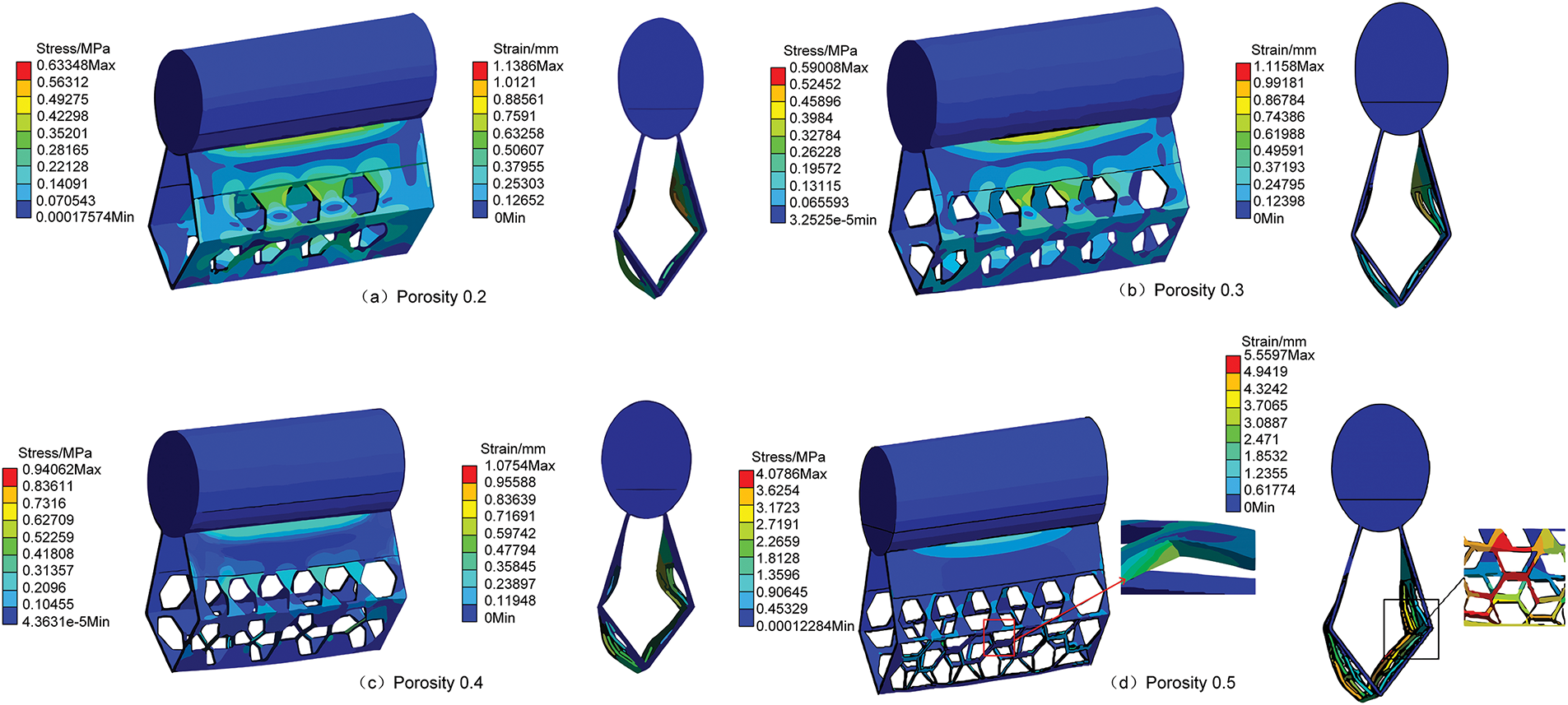
Figure 7: Stress-strain contour maps under different porosities
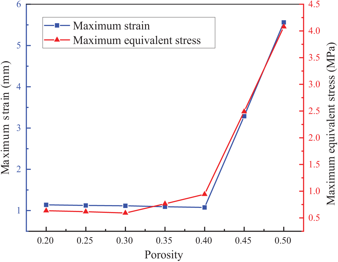
Figure 8: Relationship diagram of maximum stress and strain under different porosities
Based on Figs. 7 and 8, it is evident that when the porosity exceeds 0.4, the stress and strain on the oil containment boom increase sharply, affecting its structural stability. According to Fig. 7d, when K = 0.5, a torsional displacement occurs along the Z-axis, leading to strength failure, and the oil containment boom tends toward structural failure. At this point, the maximum equivalent stress and maximum tensile deformation occur in the hole section at the lower part of the first hole barrier.
The variation in porosity has a significant impact on the impact resistance and stability of the oil containment boom. When the porosity is below 0.4, the maximum equivalent stress is concentrated at the connection between the skirt and the float, and the maximum tensile deformation occurs at the connection between the first hole barrier and the solid fabric of the skirt. When the porosity exceeds 0.4, the stress and strain on the oil containment boom increase sharply. When K = 0.5, a torsional displacement occurs along the Z-axis, leading the oil containment boom towards structural failure. At this point, the maximum equivalent stress appears in the hole at the lower part of the first hole barrier, and the maximum tensile deformation occurs at the same location. This is because, as the porosity increases, the material of the skirt of the oil containment boom decreases, reducing its tensile performance.
When the porosity is in the range of [0.2, 0.4], the maximum equivalent stress does not exceed 1 MPa and there is an inflection point, allowing the oil containment boom to effectively reduce the impact force of water flow while maintaining good tensile strength. However, when the porosity exceeds this range, the impact resistance and stability of the oil containment boom begin to decline. When the porosity K = 0.5, the maximum equivalent stress reaches 4.078 MPa, an increase of 591.1%. To further reduce oil spill losses, the optimal porosity for the new type of oil containment boom should be in the range of [0.2, 0.3], where it can both reduce the impact force of water flow and maintain a certain level of tensile strength.
With a fixed skirt angle of α = 30° and a porosity of 0.2, simulations were conducted with inscribed circle radii of 10, 20, 30, 40, 50, 60, and 70 mm. Some of the simulation results are shown in Fig. 9. The relationship between hole size and maximum stress and strain is illustrated in Fig. 10.
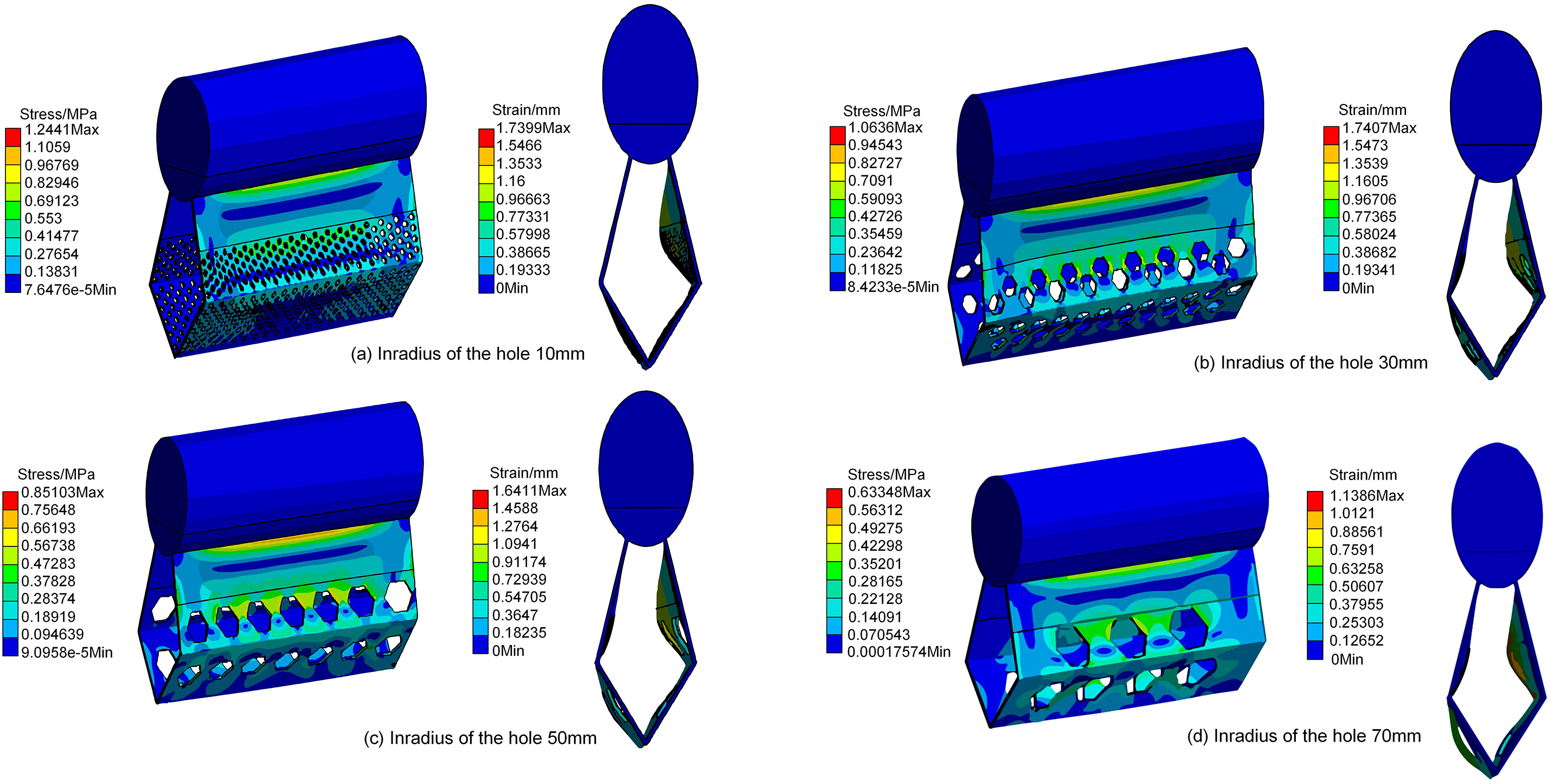
Figure 9: Stress-strain contour maps under different inradius of the hole
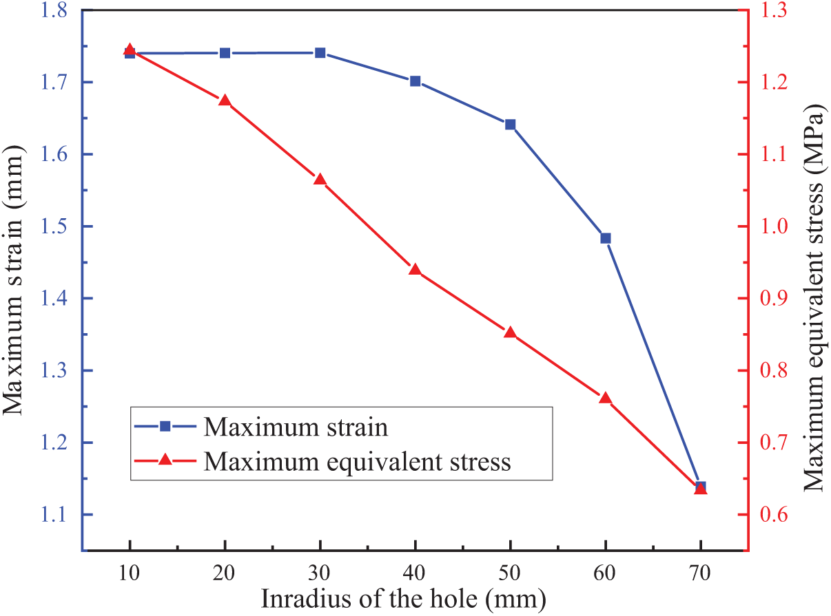
Figure 10: Relationship diagram of maximum stress and strain under different inradius of the hole
According to Figs. 9 and 10, as the inscribed circle radius of the hole increases, both the maximum elongation and equivalent stress values tend to decrease. The maximum equivalent stress is concentrated at the connection between the skirt and the float. The maximum tensile deformation occurs at the connection between the first hole barrier and the solid fabric of the skirt. The equivalent stress near the hole in the upper part of the first hole barrier is relatively high. This phenomenon might be due to the hole structure in this area affecting the flow characteristics of the fluid, leading to a localized concentration of stress distribution.
When the inscribed circle radius R = 10 mm, the maximum equivalent stress reaches 1.244 MPa. As the radius increases, the maximum equivalent stress gradually decreases. When the radius increases to R = 70 mm, the maximum equivalent stress is reduced by 49.1%. Therefore, from the perspective of optimizing mechanical performance, selecting an inscribed circle radius of R = 70 mm can effectively reduce the maximum equivalent stress experienced by the oil containment boom and improve its stress distribution characteristics. Considering the oil spill interception loss, the optimal range for the hole’s inscribed circle radius is determined to be [50, 70 mm]. In practical applications, reasonably adjusting the hole area and structure helps further enhance the mechanical performance and stability of the oil containment boom.
3.4 Analysis of Mechanical Performance between New and Old Oil Containment Booms
To further verify the impact of these parameters on the mechanical performance of the oil containment boom, based on the aforementioned studies, the optimized dimensional parameters for the mechanical structure of the new oil containment boom in a rapid-flow river environment are set as follows: a skirt angle of 30°, a porosity of 0.3, and a hole inscribed circle diameter of 70 mm. A comparative simulation group of the traditional single-segment oil containment boom is set under the same conditions, and simulation analysis is conducted in the same environment.
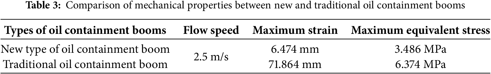
Taking the maximum value of the rapid flow speed range u = 2.5 m/s for calculation and analysis, the results are shown in Fig. 11. The surface pressure of the new type of oil containment boom is mainly concentrated on the upper half of the first skirt and the inner side at the bending point of the second skirt. In contrast, the surface pressure of the traditional oil containment boom is mainly concentrated at the central part of the skirt near the float, evenly diffusing and decreasing outward. Compared to the traditional oil containment boom, the new type exhibits significant advantages in terms of maximum tensile deformation and maximum equivalent stress. As shown in the data results of Table 3, the maximum tensile deformation of the new oil containment boom is reduced by 91.1%, and the maximum equivalent stress is reduced by 45.3%.
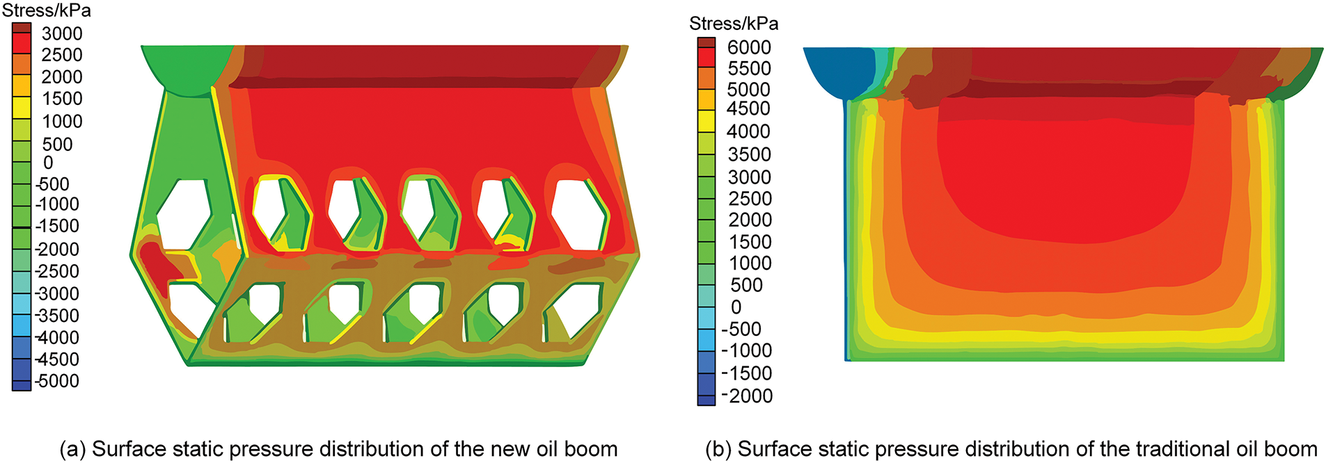
Figure 11: Pressure distribution contour maps of the oil containment boom
This study focuses on the structural optimization and performance analysis of a double-layer hole oil containment boom designed for oil spill control in rapid-flow rivers. From the perspective of mechanical performance, it examines the impact of skirt angle, porosity, and hole size on the stress-strain behavior of the oil containment boom, identifying the key parameter ranges for the new boom’s dimensional design. Additionally, by comparing the mechanical behavior of the new and traditional oil containment booms at a water flow speed of 2.5 m/s, it is found that the maximum equivalent stress of the new boom is reduced by 45.3%, further confirming its mechanical structural advantages in swift current environments. The study concludes the following:
1. The larger the skirt angle, the greater the stress and strain. From a mechanical perspective, the skirt angle of the oil containment boom should be further reduced to make the hole as perpendicular as possible to the flow direction. However, from a geometric perspective of oil spill isolation, a larger skirt angle is more beneficial for isolating oil spills and reducing the loss due to entrainment failure. Therefore, the skirt angle should be controlled within the range of [30°, 45°].
2. The effect of porosity on the mechanical performance of the oil containment boom is more direct. From a mechanical perspective, it should be controlled between [0.2, 0.4]. To further reduce oil spill losses, porosity should be appropriately decreased, thus the optimized porosity range is selected as [0.2, 0.3].
3. The larger the hole area, the smaller the stress and strain of the oil containment boom. Considering that the relationship between hole area and maximum equivalent stress is essentially linear, and the maximum equivalent stress decreases by less than 50% from an inscribed circle radius of R = 10 mm to R = 70 mm, while also considering the oil spill interception loss, the optimized range for the inscribed circle radius of the hole is determined to be [50, 70].
4. By comparing the mechanical behavior of the new and traditional oil containment booms in a numerical flume at 2.5 m/s, it is found that the maximum equivalent stress of the new boom is reduced by 45.3%, indicating a higher resistance to rapid flow impact. This provides support for further rational selection in the design of the new oil containment boom, based on the safety of its mechanical structure.
Previous related studies have mainly focused on calm waters such as seas, whereas this paper investigates oil spill control in rapid-flow rivers, filling a gap in the relevant field. Additionally, this study improves upon the traditional double-layer oil containment boom by addressing its cumbersome arrangement and high cost, while enhancing oil containment effectiveness without compromising mechanical performance. This provides new insights for the emergency response to river oil spill pollution incidents and environmental safety assurance.
Acknowledgement: Not applicable.
Funding Statement: The authors received no specific funding for this study.
Author Contributions: The authors confirm contribution to the paper as follows: study conception and design: Liqiong Chen, Jie Pang; analysis and interpretation of results: Liqiong Chen, Jie Pang, Kai Zhang; data collection: Kai Zhang; Juemei Pang; draft manuscript preparation: Jie Pang, Quan Fang; rework & communications: Kai Zhang; guidance and recommendations: Haonan Liu. All authors reviewed the results and approved the final version of the manuscript.
Availability of Data and Materials: The authors confirm that the data supporting the findings of this study are available within the article.
Ethics Approval: Not applicable.
Conflicts of Interest: The authors declare no conflicts of interest to report regarding the present study.
References
1. Galieriková A, Materna M. World seaborne trade with oil: one of main cause for oil spills? Transp Res Procedia. 2020;44(3):297–304. doi:10.1016/j.trpro.2020.02.039. [Google Scholar] [CrossRef]
2. Chen J, Zhang W, Wan Z, Li S, Huang T, Fei Y. Oil spills from global tankers: status review and future governance. J Clean Prod. 2019;227(4):20–32. doi:10.1016/j.jclepro.2019.04.020. [Google Scholar] [CrossRef]
3. Little DI, Sheppard SRJ, Hulme D. A perspective on oil spills: what we should have learned about global warming. Ocean Coast Manag. 2021;202(1):105509. doi:10.1016/j.ocecoaman.2020.105509. [Google Scholar] [CrossRef]
4. Liu B, Sun BL, Diao Y, Zheng J, Zhao YF, Liu LX. Evaluation model for potential river pollution of oil pipeline leakage and its application. Oil Gas Storage Transp. 2015;34(1):67–71. doi:10.6047/j.issn.1000-8241.2015.01.014. [Google Scholar] [CrossRef]
5. Wang S, Yan JN, Yang YF, Xu S. Quantitative environmental risk assessment model for oil spills in river basin. J Saf Environ. 2023;23(4):1349–56. [Google Scholar]
6. Du J, Wang J, Wang MR, Wu N. Robust optimal arrangement of oil containment booms for major marine oil spillaccident. Navig China. 2023;46(2):113–9. [Google Scholar]
7. Purohit BK, Tewari S, Prasad KSNV, Talari VK, Pandey N, Choudhury P, et al. Marine oil spill clean-up: a review on technologies with recent trends and challenges. Reg Stud Mar Sci. 2024;80(4):103876. doi:10.1016/j.rsma.2024.103876. [Google Scholar] [CrossRef]
8. Heshka NE, Ridenour C, Saborimanesh N, Xin Q, Farooqi H, Brydie J. A review of oil spill research in Canadian Arctic marine environments. Mar Pollut Bull. 2024;209(8–10):117275. doi:10.1016/j.marpolbul.2024.117275. [Google Scholar] [PubMed] [CrossRef]
9. Kurniawan SB, Imron MF, Roziqin A, Pambudi DSA, Alfanda BD, Ahmad MM, et al. Cases of oil spills in the Indonesian coastal area: ecological impacts, health risk assessment, and mitigation strategies. Reg Stud Mar Sci. 2024;79(6):103835. doi:10.1016/j.rsma.2024.103835. [Google Scholar] [CrossRef]
10. Li FX, Dong HC, Liang MC. Analysis, treatment and countermeasures on oil spills at sea. In: IOP Conference Series: Materials Science and Engineering; 2018 Feb 24–26; Bangkok, Thailand. [Google Scholar]
11. Shi PR, Wang YH. Research on a remote boom deployment device for near-shore oil spills. In: International Conference on Mechanical Design and Simulation (MDS 2022); 2022 Mar 18–20; Wuhan, China. [Google Scholar]
12. Wang YM, Ji CT, Bai X, Li LT, Wu HB. Design of a mobile app for standardized deployment and control of oil spill containment booms in rivers. J Yunnan Norm Univ. 2024;44(4):24–7. [Google Scholar]
13. Feng X, Zhang BY. Applications of bubble curtains in marine oil spill containment: hydrodynamic characteristics, applications, and future perspectives. Mar Pollut Bull. 2023;194(Pt A):115371. doi:10.1016/j.marpolbul.2023.115371. [Google Scholar] [PubMed] [CrossRef]
14. Hou SP, Wang Q, Yu HY, Zhang J, Huang WL. Simulative siege of oil study of shipborne lash-up oil boom laid close to broken hull. Ship Eng. 2017;39(11):49–52. [Google Scholar]
15. Wang FJ, Lei S, Xue MS, Ou JF, Li W. In situ separation and collection of oil from water surface via a novel superoleophilic and superhydrophobic oil containment boom. Langmuir. 2014;30(5):1281–9. doi:10.1021/la403778e. [Google Scholar] [PubMed] [CrossRef]
16. Wei F, Xu Y. Numerical simulation of oil booms shape optimisation. Chin J Hydrodyn A. 2011;26(06):697–703. [Google Scholar]
17. Xing F, Yang S. Numerical study of containment of spilled medium-viscosity oil in wave-current flow. J Eng Mech. 2019;145(8):04019056. doi:10.1061/(ASCE)EM.1943-7889.0001634. [Google Scholar] [CrossRef]
18. Liu JQ, Jiao PG, Xu YT. Simulation study of oil fence based on SPH method. J Shandong Jiaotong Univ. 2024;32(1):116–23. [Google Scholar]
19. Pei ZB, Li H, Yang XF. SPH-EBG simulation of oil spill containment by a flexible boom. Acta Mech Sin. 2022;39(2):722135. doi:10.1007/s10409-022-22135-x. [Google Scholar] [CrossRef]
20. Felix P, Leon L, Gay D, Salon S, Azamathulla H. A CFD model to evaluate near-surface oil spill from a broken loading pipe in shallow coastal waters. Fluid Dyn Mater Process. 2024;20(1):59–77. doi:10.32604/fdmp.2023.028031. [Google Scholar] [CrossRef]
21. Dhaka A, Chattopadhyay P. A review on physical remediation techniques for treatment of marine oil spills. J Environ Manag. 2021;288:112428. doi:10.1016/j.jenvman.2021.112428. [Google Scholar] [PubMed] [CrossRef]
22. Hou TT, Sun HY, Jiao B, Wang GX, Lin HH, Liu H, et al. Numerical and experimental study of oil boom motion response and oil-stopping effect under wave-current action. Ocean Eng. 2024;291(1):116439. doi:10.1016/j.oceaneng.2023.116439. [Google Scholar] [CrossRef]
23. Yang HT, Zhang C. Numerical simulation of containment performance and shape optimization of float oil boom. Nav Archit Ocean Eng. 2018;34(06):63–8. [Google Scholar]
24. Hou TT, Sun HY, Li HW. Study on the oil stopping effect of boom under wave-current coupling effect. China Water Transp. 2024;34–7.doi:10.13646/j.cnki.42-1395/u.2024.01.11. [Google Scholar] [CrossRef]
25. Zhao JP, An W, Zhang QF, Jin WW, Liu BZ. Design of oil boom of submersible oil at sea. Ship Ocean Eng. 2020;49(2):45–8. [Google Scholar]
26. Xing J, Chen S, Stagonas D, Yang L. Numerical modelling of oil containment process under current and waves. Ocean Eng. 2023;278(6):114356. doi:10.1016/j.oceaneng.2023.114356. [Google Scholar] [CrossRef]
27. Hao ZR, Bie HY, Bai ZY. The effect and flow field characteristics of oil booms with different structures. Adv Mater Res. 2013;726–731:1581–4. doi:10.4028/www.scientific.net/AMR.726-731.1581. [Google Scholar] [CrossRef]
28. Fang JZ, Wong K-FV. Instability study of oil slicks contained by a single boom. In: Arctic and Marine Oilspill Program Technical Seminar; 2000 Jun 14–16; Vancouver, BC, Canada. [Google Scholar]
29. Babaei H, Baker S, Cornett A, Pilechi A. Two-dimensional computational and physical modeling of high-speed Oil Spill Contain Booms. J Waterway, Port, Coast Ocean Eng. 2021;147(6):04021032. doi:10.1061/(ASCE)WW.1943-5460.00006. [Google Scholar] [CrossRef]
30. GB/T 34621-2017. Oil containment booms. Beijing, China: General Administration of Quality Supervision, Inspection and Quarantine, National Standards Committee; 2017. [Google Scholar]
31. Jin RJ, Chen SG, Geng BL. Experimental study on large scale physical model of dynamic characteristics of oil containment boom. In: Chinese Society of Offshore Engineering Proceedings of the 19th China Ocean (Offshore) Engineering Symposium (below) Ocean Engineering Society of China: Ocean Engineering Branch of the Ocean Society of China; 2019 Oct 12–15; Chongqing, China. p. 53–8. [Google Scholar]
32. Zodiatis G, Robin Lardner TMA, Krestenitis Y, Perivoliotis L, Sofianos S, Spanoudaki K. Oil spill forecasting (prediction). J Mar Res. 2017;75(6):923–53. doi:10.1357/002224017823523982. [Google Scholar] [CrossRef]
33. Chen LQ, Liu SH, Zhang P, Xu D, Hu HX. Design and optimisation of oil spill recovery devices for fast-flowing river. Sci Technol Eng. 2025;25(2):553–9. [Google Scholar]
34. Shinde V, Marcel T, Hoarau Y, Deloze T, Harran G, Baj F, et al. Numerical simulation of the fluid-structure interaction in a tube array under cross flow at moderate and high Reynolds number. J Fluids Struct. 2014;47(3/4):99–113. doi:10.1016/j.jfluidstructs.2014.02.013. [Google Scholar] [CrossRef]
35. Li ZG, Jiang MR, Yu JX. Numerical simulation of subsea pipeline oil spill diffusion based on VOF method. J Hydrodyn. 2016;34(6):100–10. [Google Scholar]
Cite This Article
 Copyright © 2025 The Author(s). Published by Tech Science Press.
This work is licensed under a Creative Commons Attribution 4.0 International License , which permits unrestricted use, distribution, and reproduction in any medium, provided the original work is properly cited.
 Downloads
 Citation Tools