
 Submit a Paper
 Propose a Special lssue
 Open Access
ARTICLE

A Method for Preventing Crack Propagation in a Steel Gas Conduit Reinforced with Composite Overlays
1 Department of Architecture and Urban Planning, Mukhtar Auezov South Kazakhstan University, Tauke Khan av., 5, Shymkent, 160012, Kazakhstan
2 Department of Architecture and Industrial Design, University of Campania “Luigi Vanvitelli”, Via San Lorenzo ad Septimum, Aversa, 81031, Italy
3 Department of Scientific and Innovative Work, Peoples’ Friendship University named after Academician A. Kuatbekov, Tole bi str., 32B1, Shymkent, 160011, Kazakhstan
* Corresponding Authors: Nurlan Zhangabay. Email: ; Marco Bonopera. Email:
(This article belongs to the Special Issue: Intelligent Fault Diagnosis and Health Monitoring for Pipelines)
Structural Durability & Health Monitoring 2025, 19(4), 773-787. https://doi.org/10.32604/sdhm.2025.064980
Received 28 February 2025; Accepted 26 May 2025; Issue published 30 June 2025
 View Full Text
 Download PDF
Abstract
This research presents a numerical simulation methodology for optimizing circular composite overlays’ dimensions and pressure characteristics with orthotropic mechanical properties, specifically, for metal conduits with temperature-dependent elastoplastic behavior. The primary objective of the proposed method is to prevent crack propagation during pressure surges from operational to critical levels. This study examines the “Beineu-Bozoy-Shymkent” steel gas conduit, examining its performance across a temperature range of −40 to +50°C. This work builds on prior research on extended avalanche destruction in steel gas conduits and crack propagation prevention techniques. The analysis was conducted using a dynamic finite-element approach with the ANSYS-19.2/Explicit Dynamics software. Simulations of unprotected conduits revealed that increasing gas-dynamic pressure can convert a partial-depth crack into a through-crack, extending longitudinally to approximately seven times its initial length. Notably, at T = +50°C, the developed crack length was 1.2% longer than that at T = −40°C, highlighting the temperature sensitivity of crack progression. The modeling results indicate that crack propagation can be effectively controlled using a circular composite overlay with a thickness between 37.5% and 50% of the crack depth and a length approximately five times that of the initial crack, centered symmetrically over the crack. In addition, preliminary stress analysis indicated that limiting the overlay-induced pressure to 5% of the operational pressure effectively arrested crack growth without generating significant stress concentrations near the overlay boundaries, thereby preventing conduit integrity.Keywords
The continuous operation of steel gas conduits requires enhanced reliability measures because defects, particularly cracks, can lead to substantial economic losses and environmental hazards. An analysis of literature and previous investigations indicates that factors such as corrosion extending to half the conduit thickness, stress concentration near fasteners, and part-through crack defects can cause steel gas conduit failure when internal pressure escalates from operational to critical levels [1–3]. Steel main gas conduits in the Republic of Kazakhstan are exposed to temperature fluctuations ranging from +50°C to−40°C, which adversely affect structural integrity and promote crack formation and propagation [4–6]. To mitigate the risks associated with partially damaged steel main gas conduits, bandaging of affected areas is widely implemented [7–9]. Recent trends show an increasing preference for composite materials in such repairs, reflecting their superior mechanical properties and corrosion resistance. Given the significance of composites in reinforcing damaged conduit sections, extensive research has been conducted on this topic. Recent investigations have been reviewed in several publications. For example, Tafsirojjaman et al. [10] demonstrated the effectiveness of Fiber-Reinforced Polymers (FRP) for repairing steel structures, including the systematic modeling of the strength of fiberglass-reinforced steel structures under mechanical loads and environmental conditions. Hocine et al. [11] investigated the influence of parameters such as material pattern, winding angle, laying sequence, overlay thickness, length, and recovery angle on the strength of repaired steel conduits under quasi-static loading, presenting both experimental and numerical research methodologies. Furthermore, Wielhorski et al. [12] highlighted the extensive use of the Finite-Element (FE) method in three-dimensional computer simulations for assessing the mechanical behavior of woven composite materials. These studies collectively established primary approaches for numerically evaluating the strength of composite-reinforced steel gas conduits, although their analyses were largely confined to static or quasi-static models.
Fiberglass and carbic epoxy are among the most widely used composite materials for bandages in gas conduit reinforcement [13–15]. Fiberglass is known for its cost-effectiveness and exhibits viscoelastic properties under high loads. Conversely, carbic epoxy exhibits orthotropic elastic properties, exhibiting high durability even at minimal thickness [16,17]. However, limited research has specifically addressed crack development under internal gas-dynamic pressure [18,19], despite several studies focusing on the processes and conditions required for crack growth cessation. Di Biagio et al. [20], Ben amara et al. [21], and Zhang et al. [22] have explored the influence of steel conduit material properties on crack propagation. Oikonomidis et al. [23,24] conducted a detailed analysis of the relationship between deformation rates and crack opening angles, highlighting the significance of steel’s plastic properties. In addition, Altenbach et al. [25] also described methods for implementing dynamic models of metal plastic flow, providing insights into the structural deformation and failure processes. Kaputkin and Arabey [26] and Kaputkin et al. [27] examined the effects of temperature on crack behavior, highlighting the critical role of thermal conditions in material performance. Despite the widespread use of composite materials in reinforcing damaged steel gas conduits [28,29], modeling their influence on crack propagation prevention, particularly under varying temperature conditions, remains inadequately addressed in existing studies [30–32] and is largely absent in regulatory documentation [33–35].
This research builds on prior investigations into the extensive avalanche-type destruction of steel gas conduits and methods for preventing crack propagation [2,3,6,9,36]. This study presents a numerical simulation methodology for optimizing the geometric dimensions (length and width) and preliminary stress forces of circular composite overlays. The proposed approach is designed to ensure crack non-propagation in steel conduits subjected to pressure surges from operational to critical levels, across a temperature range of −40°C to +50°C.
2.1 Model of an Area of a Steel Gas Conduit with a Lengthwise Crack Reinforced Using a Composite Overlay and When Subjected to Intrinsic Gas-Dynamic Pressure
This study examines a straight section of a large-diameter steel gas conduit with a rectilinear crack located between the supports. Initial research has indicated that such cracks are the primary contributors to extensive avalanche destruction in steel gas conduits [36]. The crack is located on the outer surface of the conduit, with a depth a equal to half the conduit wall thickness H, which is defined as a = 0.5 H. Previous investigations have established that this crack depth allows steel gas conduits to operate safely under normal pressure conditions but can lead to through-crack formation when internal pressure approaches critical values [3,6,9,35]. The “Beineu-Bozoy-Shymkent” steel gas conduit was used as the case study in this investigation. The supports are spaced 36.0 m apart, and their influence on crack propagation is considered negligible. The study length L was determined based on a preliminary analysis of the development of cracks in an unmodified steel conduit. The conduit specifications included an internal radius R of 523.5 mm, a wall thickness H of 15.9 mm, and a crack depth a of 8 mm. The longitudinal crack runs perpendicular to the axial section, with initial dimensions comprising a length l of 200 mm, a width w of 1 mm, and an apex angle of 20°. A circular composite overlay covers the cracked section of the steel conduit, as shown in Fig. 1.
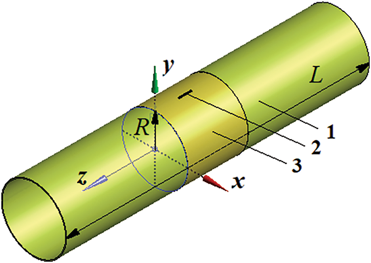
Figure 1: Schematic of a steel conduit section with a composite overlay covering a longitudinal crack: 1. large-diameter conduit section; 2. longitudinal crack; 3. circular composite overlay
The interior surface of the steel conduit was subjected to a non-stationary internal pressure, as shown in Fig. 2 [6,37,38]. The internal pressure history was derived from the experimental data presented by Nordhagen et al. [37], ensuring consistency with the conditions documented in these reference studies. Note that under actual operating conditions, the depressurization rate may be closely correlated with the crack propagation velocity. However, incorporating crack-dependent depressurization necessitates a more sophisticated modeling approach, which is beyond the scope of this study. While such an approach could provide a more comprehensive representation of the physical processes involved, the use of a predefined internal pressure history allows for a more direct analysis, which closely aligns with experimental observations. Future research could explore alternative modeling methodologies that account for the interaction between crack propagation and internal pressure variations, potentially enhancing the predictive accuracy of fracture behavior in pressurized steel pipelines.
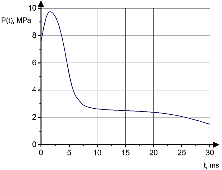
Figure 2: The internal pressure distribution on the inner surface of the steel gas conduit
This research aimed to develop a numerical simulation methodology for determining the optimal geometric dimensions and preliminary pressure forces of circular composite overlays on steel conduits. The proposed method is designed to prevent crack propagation along the conduit during pressure surges from operational levels to critical breakdown conditions. The analysis specifically considered temperature ranges from –40°C to +50°C, reflecting typical operational extremes for steel gas conduits.
2.2 Modeling of Material Properties of a Steel Gas Conduit Reinforced with Carbic Epoxy Overlay
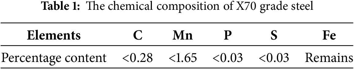
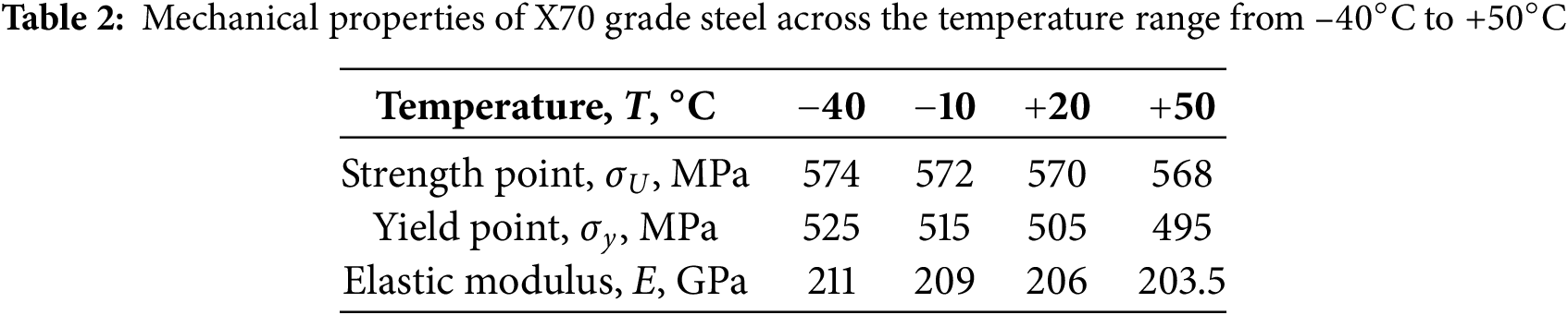
The conduit material consists of X70 grade steel, which exhibits plastic properties. The material has a density of ρ = 7810 kg/m3 and a Poisson’s ratio of μ = 0.3. Table 1 presents the chemical composition of the X70 grade steel, while Table 2 provides its mechanical properties for temperatures ranging from –40°C to +50°C. These values were obtained through linear interpolation of the experimental data. X70 grade steel, which is classified as a high-strength, low-carbon, microalloyed conduit steel, is known for its exceptional impact toughness at low temperatures. Consequently, exposure to temperatures as low as –40°C does not induce structural changes that would lead to material embrittlement [37].
The state equation for the elastic deformation of a material considering temperature effects is expressed as [37]:
where
where
where
where Cαβγδ represents the tensor coefficients of the Young’s modulus. The relation (4) for an orthotropic material is well established. Based on this relationship, the incremental changes in the direct stress for a dynamic problem can be determined as follows:
where
The dynamic failure analysis uses the stress and strain data obtained from the explicitly dynamic simulations. The numerical simulations were conducted using ANSYS Workbench with the Explicit Dynamics (Autodyn) module. The fracture criterion implemented in this study is based on plastic strain failure, where material failure occurs when the plastic strain ϵpl reaches a critical value ϵfail. The failure strain was experimentally determined for each material in the structure was experimentally determined. In the numerical implementation, the stress tensor is calculated at various points within the structure over time by solving a system of ordinary differential equations. The Courant–Friedrichs–Lewy (CFL) criterion [40,41] controls the integration time step and ensures numerical stability. The equivalent strains and strain rates were evaluated at each time step. When the plastic strain in an element reaches the failure threshold ϵfail, that element is considered fractured, and the corresponding time step is recorded as the moment of failure. The structure’s overall failure time is determined by the first occurrence of element failure in the critical regions. The approach adopted here aligns with established fracture modeling techniques, such as those described by Bao and Wierzbicki [42], where ductile fracture is characterized by a plastic strain threshold influenced by stress triaxiality. Although this study does not explicitly incorporate a triaxiality-dependent fracture locus, the methodology follows common engineering practices for impact and dynamic failure analysis.
2.3 Methodology for Selecting the Geometric Dimensions of Composite Overlay
The internal radius r of the composite overlay is the external radius of the steel conduit, r = R + H. The composite overlay is assumed to be in full contact with the conduit, ensuring a perfect fit without gaps. The initial thickness of the composite overlay is specified by the following formula [38–41]:
where
where
where
2.4 FE Model in ANSYS/Explicit Dynamics
The problem was addressed using a dynamic formulation. The numerical solution is implemented with the “ANSYS-19.2/Explicit Dynamics” software package. Spatial discretization is based on the FE method and follows the equation of motion [3,6]. Fig. 3 shows the FE model of the problem. Grid uniformity was achieved through the Body Sizing decomposition method, which was applied separately to the steel conduit and composite overlay. The linear size of the FE was determined relative to the thickness of the body, which was divided into elements. The convergence of the FE model was verified using the standard method for FE size reduction. The test calculations indicate that a grid with four elements across the conduit thickness and two elements across the composite overlay thickness ensures solution convergence. This approach effectively models crack growth along the lengthwise direction, addressing challenges that are not typically encountered in static analyses. Conventional methods, including grid refinement at the crack tip, which are commonly used in static problems, are impractical for this investigation.
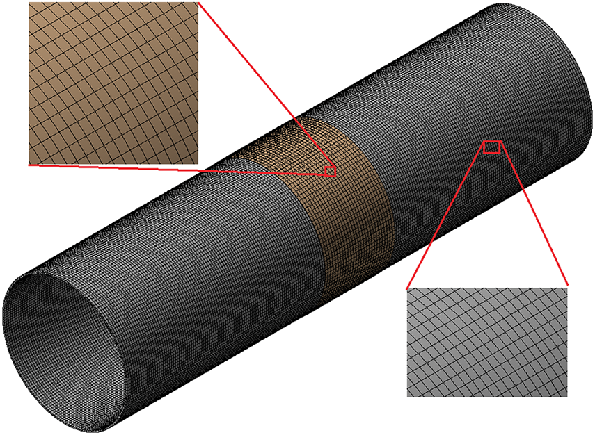
Figure 3: FE model
3.1 Modeling of Crack Propagation in a Steel Gas Conduit without a Composite Overlay
Numerical simulation of the destruction dynamics in a steel conduit with a crack, subjected to gas-dynamic internal pressure, across a temperature range from −40°C to +50°C, facilitates the evaluation of crack growth and the influence of temperature on its progression. The analysis revealed that the most critical temperature for crack propagation in the lengthwise direction is Т = +50°C. At this temperature, the crack length exceeded that at Т = −40°C by 1.2%. The crack development dynamics are illustrated in Fig. 4, which presents the data obtained at Т = +50°C. The destruction pattern remained qualitatively consistent throughout the specified temperature range, as reflected by the results in Fig. 4.
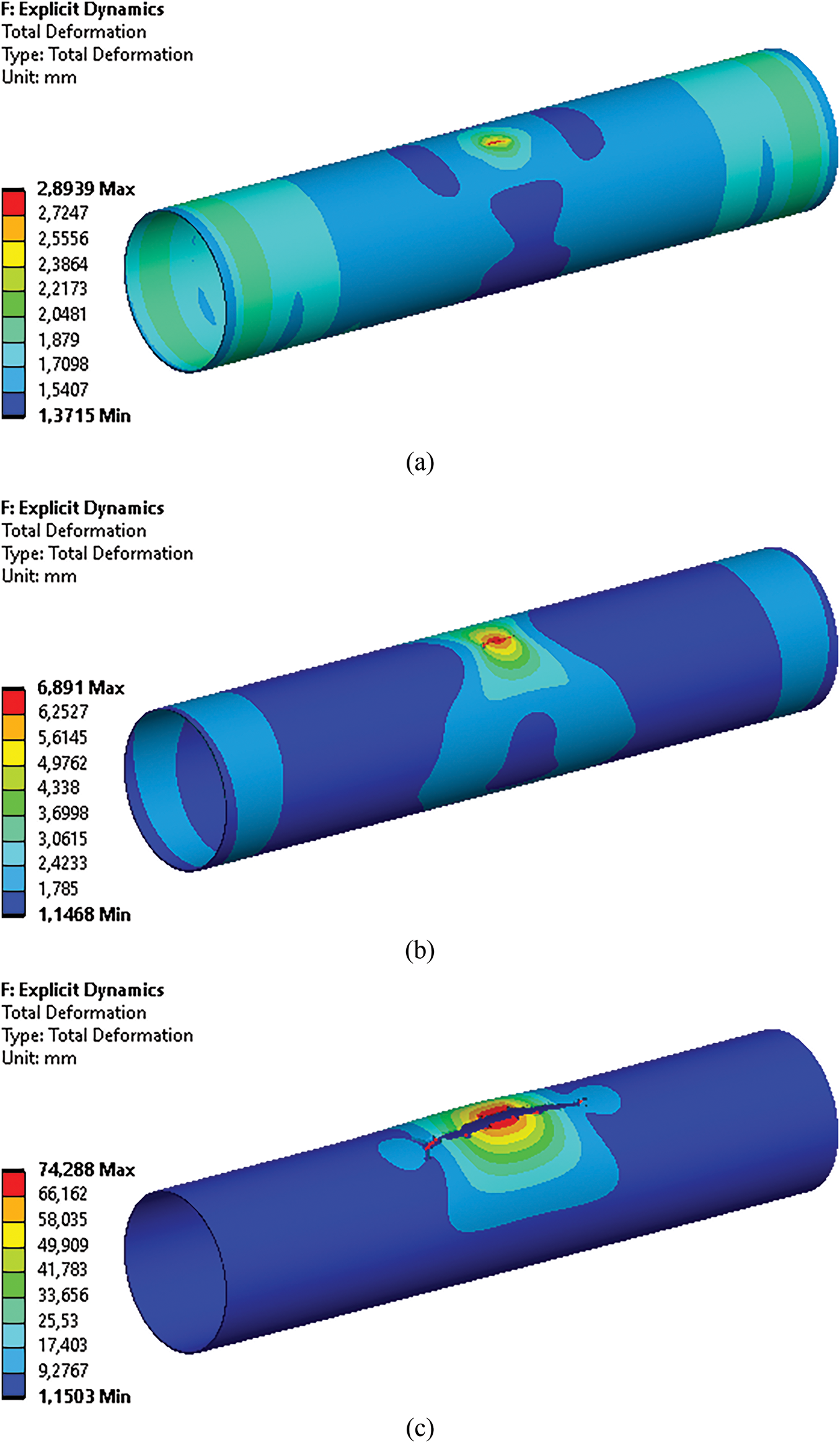
Figure 4: Displacements in a steel gas conduit with a crack and without a composite overlay: a—at a time of 2.0 ms; b—at a time of 3.0 ms; c—at a time of 5.0 ms
Analysis of the findings reveals the progression pattern of a non-through crack and the initiation of avalanche destruction in the steel conduit. As the pressure increases from the production level to the breakdown point, the part-through crack deepens within the steel conduit. By the second millisecond of the deformation process, the crack is transformed into a through crack (Fig. 4a). Subsequently, the edges of the through crack separate and begin expanding along the lengthwise direction (Fig. 4b). The crack continued to extend lengthwise until 5.0 ms (Fig. 4c). Notably, the final length of the developed through crack was 1.384 mm, representing a 6.92-fold increase from the initial part-through crack length.
3.2 Modeling of the Length and Thickness of the Composite Overlay
The initial thickness of the composite overlay was determined according to Eq. (6) and in consideration of the manufacturing technology for thin-walled carbic epoxy shells [41]. The modeling of crack propagation prevention through steel gas conduit reinforcement with composite overlays was modeled using overlay thicknesses of 2.0, 3.0, and 4.0 mm, respectively. Studies were conducted across a temperature range of −40°C to +50°C. Results indicated that a 2.0 mm-thick composite overlay fails to maintain structural integrity when a through crack forms. However, composite overlays with thicknesses of 3.0 and 4.0 mm were found to be suitable, with both options maintaining similar stress levels in the reinforced steel conduit. Further analysis demonstrated that increasing the composite overlay thickness beyond 5.0 mm generates undesirable stress concentrations in the steel conduit and near its overlay edges. Similar to the non-overlay case, +50°C remains the most critical condition for crack development in the lengthwise direction.
The composite overlay length was modeled according to Eq. (8) with a thickness of 3.0 mm. Given that the crack extends almost sevenfold without the composite overlay, the sum
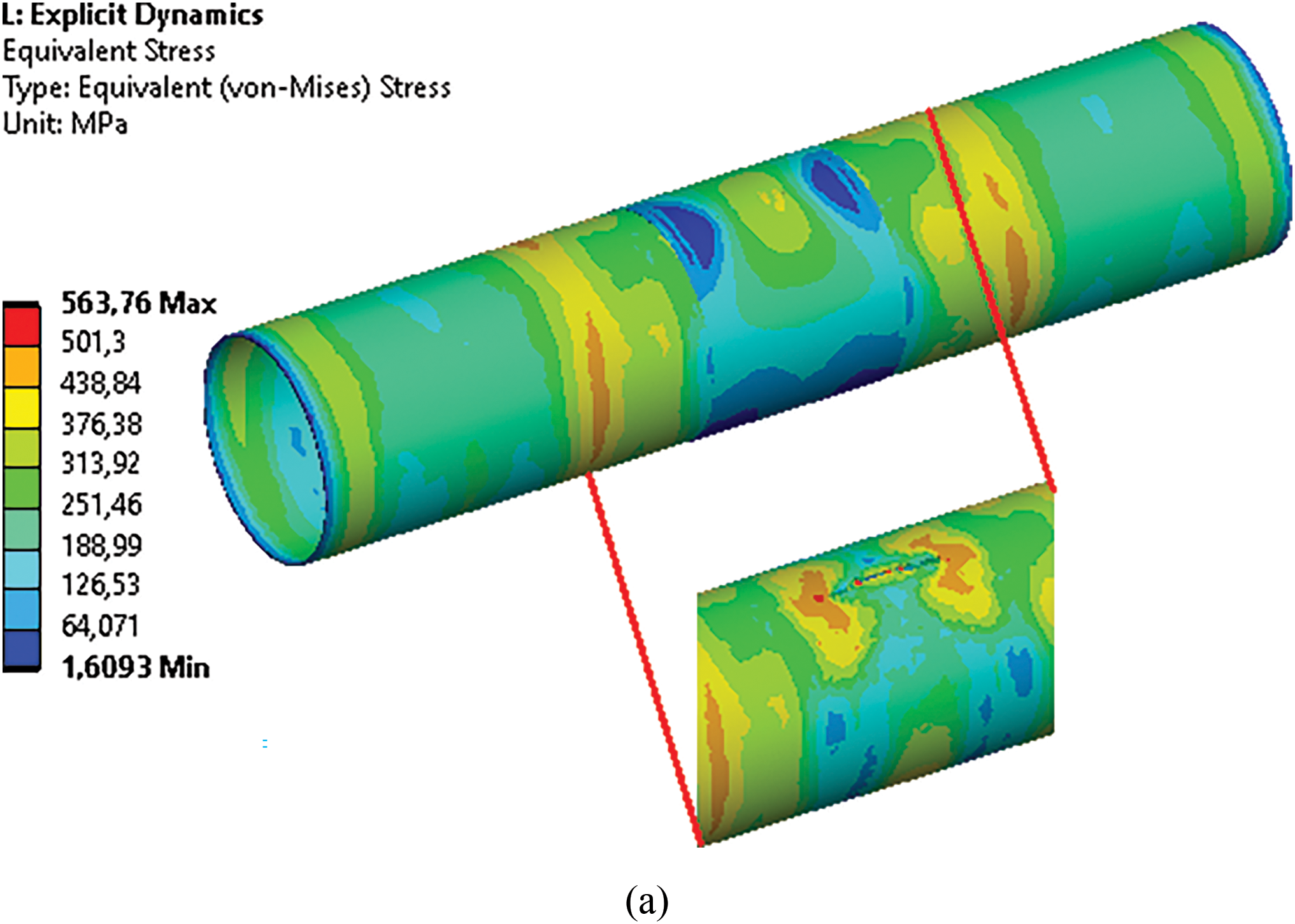
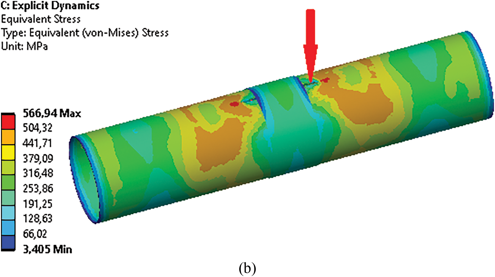
Figure 5: Stresses along the steel gas conduit with a crack at a time of 5.0 ms, with a 3.0 mm in thickness overlay and lengths of: (a) 1000 mm and (b) 600 mm (temperature as great as +50 degrees)
Analysis of the results indicates that a 600 mm composite overlay is insufficient to prevent failure of the steel gas conduit. In contrast, the 1000 mm composite overlay effectively halted crack propagation in the longitudinal direction. The stress levels in the steel gas conduit outside the composite overlay remained below the yield point, whereas stresses within the overlay were substantially lower than their allowable limits. Stresses exceeding the yield point but remaining below the tensile strength are observed only at the crack tips beneath the composite overlay.
3.3 Modeling of Prestressed State of the Composite Overlay
Implementing composite overlays for reinforcing steel gas conduits operating across a wide temperature range requires careful consideration of temperature deformations [40]. The junction between materials with differing thermal expansion coefficients demands attention because the full contact assumed in steel/carbic epoxy joints at room temperature may deteriorate at −40°C. To prevent this deterioration, the circular composite overlay was secured under tension. This approach creates a prestressed state in the steel conduit contact area, as modeled here by applying a stationary, uniformly distributed pressure on the contact surface. This investigation examines how prestresses influence the dynamic deformation and failure of a bandaged steel conduit containing a non-through longitudinal crack. The critical temperature condition occurs at +50°C during deformation.
The analysis of crack development in a prestressed steel conduit can be performed in various pressure ranges. Fig. 6 illustrates the stress distributions along the conduit for pressures of 5% (Fig. 6a) and 10% (Fig. 6b) of the producing pressure along the conduit. Research demonstrates that overlay pressure not exceeding 5% of the produced pressure. The results demonstrate that overlay pressures not exceeding 5% of the produced pressure effectively arrest longitudinal crack propagation. Under these conditions, the steel conduit deformation remained predominantly elastic, except for localized zones near the crack tips, with no significant stress concentration along the conduit (Fig. 6a). However, when the overlay pressure exceeds 5%, pronounced stress concentration zones develop near the overlay edges (Fig. 6b), with the stress magnitudes surpassing the elastic limit, rendering such conditions unsuitable. Similar stress patterns were observed for composite overlays thicker than 5.0 mm. This study maintains a constant fracture toughness, KIC, focusing primarily on the influence of external reinforcement on crack propagation within specific pressure ranges. Although KIC typically varies with temperature and significantly affects crack behavior, a detailed analysis of temperature-dependent fracture toughness requires additional experimental data and material characterization beyond the scope of this study. Future research should address the effects of temperature on KIC for a comprehensive assessment of crack propagation in prestressed steel pipelines reinforced with composite overlays. In addition, this investigation excluded the effects of the hydrogen environment and other environmental factors, such as pH, on crack growth. Although hydrogen notably influences crack growth rate, particularly at varying temperatures, analyzing this effect necessitates further research involving specialized experiments and FE model modifications. Moreover, the J-integral method was not employed to determine the crack propagation direction because the study focused on the role of external reinforcement in preventing crack opening under specified pressure conditions. Investigation into the effects of hydrogen on the environment, pH influence, and the application of the J-integral represents important avenues for future research, contributing to a more comprehensive understanding of fracture processes under service conditions.
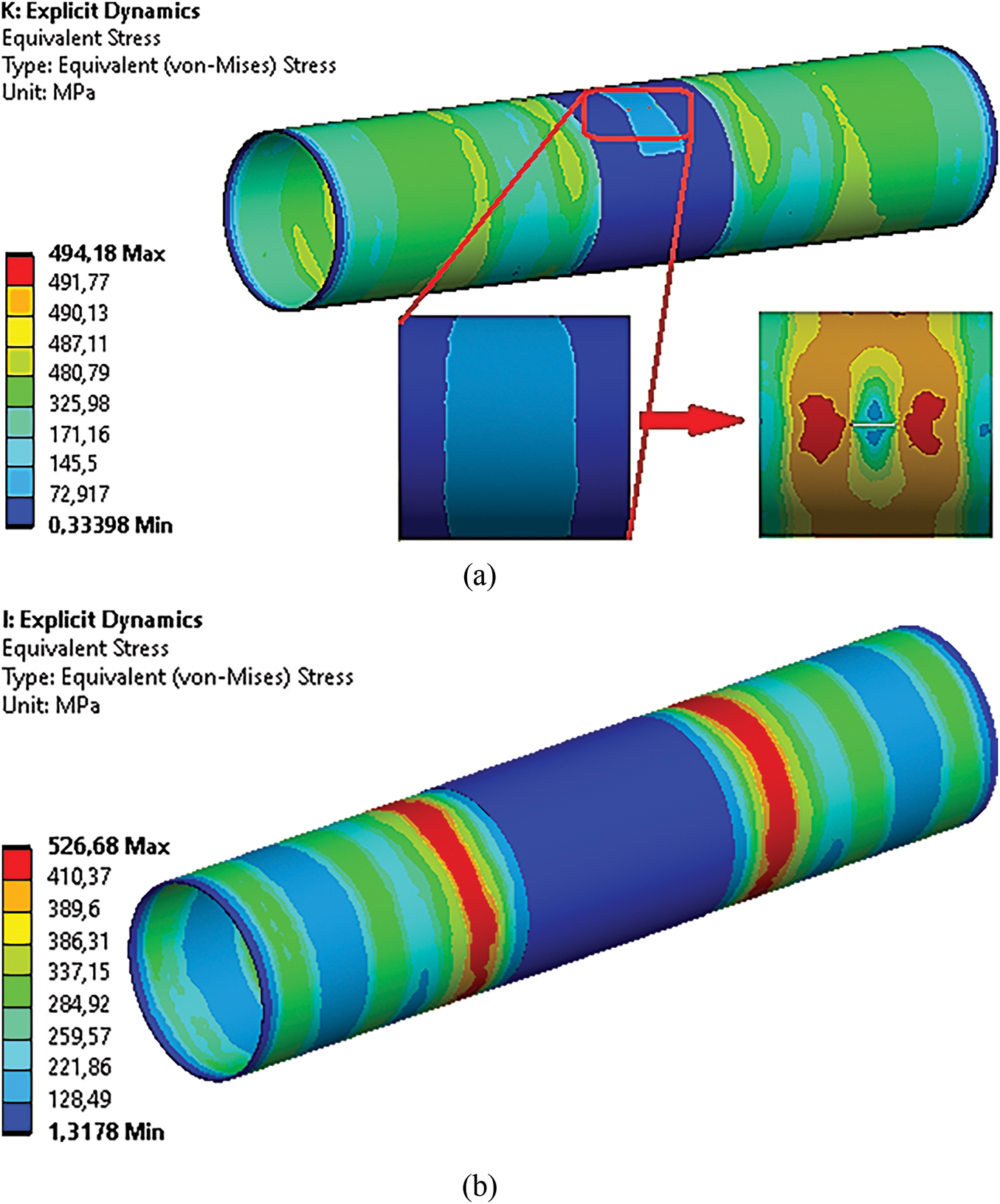
Figure 6: Stresses along the steel gas conduit with a crack at a time of 5.0 ms, considering the pressure of the overlay on the conduit: (a) 375 and (b) 750 kPa
The analysis revealed that the crack length along the steel conduit reinforced with a composite overlay applying pressure to the conduit’s outer face (Fig. 6a) was shorter than that in a conduit reinforced with a composite overlay that did not exert such pressure (Fig. 5a). Notably, across all numerical simulations, the stress within the carbon fiber overlay ranged from 30 to 60 MPa, which is significantly below the ultimate tensile strength of carbon fiber composites. Consequently, the presence of an overlay in the through-crack region effectively counteracts the influence of internal pressure and inhibits further crack opening.
This study investigated methods to prevent crack propagation in the full-scale main steel gas conduit “Beineu-Bozoy-Shymkent” under operational conditions, with particular focus on the effects of temperature and carbic epoxy composite overlays. The research included a parametric analysis of crack propagation and localization with composite patches, examining temperature loads ranging from −40°C to +50°C on the steel conduit material under operating conditions, with pressure increases from production to breakdown levels. In Section 3, the most effective geometric parameters for the composite overlays were identified, and their performance in preventing crack propagation. This theoretical research on crack propagation prevention modeling forms part of a broader study aimed at improving the mechanical properties of steel gas conduits under operational conditions [2,3,5,6,37]. Earlier phases of the research investigated alternative prevention methods for crack propagation using steel rings and steel wrapping, which showed high effectiveness. These methods were validated through theoretical modeling [2,3,6,37] and experimental studies conducted on scaled-down steel conduit models [5], demonstrating strong agreement between theory and experiments. The next research phase will involve experimental testing on scaled-down main steel gas conduit models to assess crack propagation prevention using composite overlays, following the methodology of Zhangabay et al. [5]. The experimental results are then compared with the theoretical findings. Although this study did not consider frictional forces between the composite patch and the steel conduit, this limitation does not diminish the significance of the findings and will be addressed in future research.
Bandaging damaged areas of steel gas conduits with composite overlays is widely used to mitigate the risks associated with cracks. This research presents a numerical simulation approach to determine the optimal geometric dimensions (length and thickness) and the pressure force of circular carbic epoxy overlays applied to steel conduits, ensuring that crack non-propagation is prevented during pressure increases from production to breakdown levels. The study considers a temperature range from −40°C to +50°C. Building on previous investigations of avalanche-type destruction in steel gas conduits and crack non-propagation strategies, the present analysis employs a dynamic formulation using the FE method implemented in the ANSYS-19.2/Explicit Dynamics software. Modeling crack propagation without composite overlays showed that rising intrinsic gas-dynamic pressure transforms a partial-depth crack into a through crack, which then extends longitudinally to approximately seven times its initial length. At +50°C, the crack length was 1.2% longer than that at −40°C. Modeling the composite overlay dimensions revealed that a circular overlay with a thickness between 37.5% and 50% of the crack depth and a length five times the initial crack length effectively prevents longitudinal crack propagation. Furthermore, the preliminary stress analysis indicated that applying an overlay pressure below 5% of the production pressure successfully halted crack growth without causing significant stress concentrations near the overlay edges. This numerical simulation method, which accounts for temperature-dependent material properties, offers an effective means to optimize the repair parameters of gas conduits. While this study focuses specifically on the “Beineu-Bozoy-Shymkent” steel gas conduit, the methodology is adaptable to various damaged scenarios and conduit types in the oil and gas industry.
Acknowledgement: The authors express their gratitude to the A. Pidhornyi Institute of Mechanical Engineering Problems of the National Academy of Sciences of Ukraine for providing advisory support for this research.
Funding Statement: This research was supported by the Science Committee of the Ministry of Science and Higher Education of the Republic of Kazakhstan (Grant No. AP19680589).
Author Contributions: Conceptualization, Nurlan Zhangabay and Ulanbator Suleimenov; Methodology, Nurlan Zhangabay and Marco Bonopera; Investigation, Nurlan Zhangabay; Data curation, Nurlan Zhangabay, Shairbek Yeshimbetov and Ulzhan Ibraimova; Writing—original draft preparation, Nurlan Zhangabay, Marco Bonopera and Ulzhan Ibraimova; Writing—review and editing, Nurlan Zhangabay and Ulzhan Ibraimova; Supervision, Nurlan Zhangabay and Shairbek Yeshimbetov; Project administration, Nurlan Zhangabay; Funding acquisition, Nurlan Zhangabay. All authors reviewed the results and approved the final version of the manuscript.
Availability of Data and Materials: Data sharing is not applicable to this manuscript.
Ethics Approval: Not applicable.
Conflicts of Interest: The authors declare no conflicts of interest to report regarding the present study.
References
1. Zardasti L, Yahaya N, Valipour A, Rashid ASA, Noor NM. Review on the identification of reputation loss indicators in an onshore pipeline explosion event. J Loss Prev Process Ind. 2017;48(4):71–86. doi:10.1016/j.jlp.2017.03.024. [Google Scholar] [CrossRef]
2. Zhangabay N, Ibraimova U, Suleimenov U, Moldagaliyev A, Buganova S, Jumabayev A, et al. Factors affecting extended avalanche destructions on long-distance gas pipe lines: review. Case Stud Constr Mater. 2023;19(115):e02376. doi:10.1016/j.cscm.2023.e02376. [Google Scholar] [CrossRef]
3. Zhangabay N, Ibraimova U, Bonopera M, Suleimenov U, Avramov K, Chernobryvko M, et al. Finite-element modeling of the dynamic behavior of a crack-like defect in an internally pressurized thin-walled steel cylinder. Appl Sci. 2024;14(5):1790. doi:10.3390/app14051790. [Google Scholar] [CrossRef]
4. da Cunha SB. A review of quantitative risk assessment of onshore pipelines. J Loss Prev Process Ind. 2016;44(2008):282–98. doi:10.1016/j.jlp.2016.09.016. [Google Scholar] [CrossRef]
5. Zhangabay N, Ibraimova U, Tursunkululy T, Buganova S, Moldagaliev A, Duissenbekov B. Experimental study of avalanche damage protection methods for main steel gas pipelines. Materials. 2024;17(13):3171. doi:10.3390/ma17133171. [Google Scholar] [PubMed] [CrossRef]
6. Zhangabay N, Ibraimova U, Bonopera M, Suleimenov U, Avramov K, Chernobryvko M, et al. Novel methodologies for preventing crack propagation in steel gas pipelines considering the temperature effect. Struct Durab Health Monit. 2025;19(1):1–23. doi:10.32604/sdhm.2024.053391. [Google Scholar] [CrossRef]
7. Shafaee Fallah A, Sadeghian M, Golmakani ME. Experimental and numerical study on the strength of repaired steel pipes with composite patches under internal pressure. Mech Adv Compos Struct. 2023;10(2):437–48. doi:10.22075/macs.2023.29108.1459. [Google Scholar] [CrossRef]
8. Dumitrescu A, Minescu M, Dinita A, Lambrescu I. Corrosion repair of pipelines using modern composite materials systems: a numerical performance evaluation. Energies. 2021;14(3):615. doi:10.3390/en14030615. [Google Scholar] [CrossRef]
9. Moldagaliyev A, Zhangabay N, Suleimenov U, Avramov K, Raimberdiyev T, Chernobryvko M, et al. Deformation features of trunk pipelines with composite linings under static loads. East Eur J Enterp Technol. 2023;5(7 (125)):34–42. doi:10.15587/1729-4061.2023.287025. [Google Scholar] [CrossRef]
10. Tafsirojjaman T, Ur Rahman Dogar A, Liu Y, Manalo A, Thambiratnam DP. Performance and design of steel structures reinforced with FRP composites: a state-of-the-art review. Eng Fail Anal. 2022;138(20):106371. doi:10.1016/j.engfailanal.2022.106371. [Google Scholar] [CrossRef]
11. Hocine A, Kara Achira FS, Habbar G, Levent A, Medjdoub SM, Maizia A, et al. Structural integrity assessment of corroded pipelines repaired with composite materials-literature review. Int J Press Vessels Pip. 2024;210:105253. doi:10.1016/j.ijpvp.2024.105253. [Google Scholar] [CrossRef]
12. Wielhorski Y, Mendoza A, Rubino M, Roux S. Numerical modeling of 3D woven composite reinforcements: a review. Compos Part A Appl Sci Manuf. 2022;154(6):106729. doi:10.1016/j.compositesa.2021.106729. [Google Scholar] [CrossRef]
13. Muda MF, Mohd Hashim MH, Kamarudin MK, Mohd MH, Tafsirojjaman T, Rahman MA, et al. Burst pressure strength of corroded subsea pipelines repaired with composite fiber-reinforced polymer patches. Eng Fail Anal. 2022;136(2):106204. doi:10.1016/j.engfailanal.2022.106204. [Google Scholar] [CrossRef]
14. Uspensky B, Derevianko I, Avramov K, Maksymenko-Sheiko K, Chernobryvko M. Mechanical properties of auxetic honeycombs realized via material extrusion additive manufacturing: experimental testing and numerical studies. Appl Compos Mater. 2025;32(1):119–48. doi:10.1007/s10443-024-10269-2. [Google Scholar] [CrossRef]
15. Reis JML, Menezes EM, da Costa Mattos HS, Carbas RJC, Marques EA, Silva LFM. Strength of dissimilar adhesively bonded DCB joints and its connection with the failure pressure of composite repair systems. Compos Struct. 2023;304(3–4):116441. doi:10.1016/j.compstruct.2022.116441. [Google Scholar] [CrossRef]
16. Avramov KV, Uspensky BV, Derevyanko II, Degtyaryov MO, Polishchuk OF, Chernobryvko M. Dynamic properties of nanocomposite and three-layer thin-walled aerospace elements manufactured by additive technologies. Kosm Nauka Tehnol. 2023;29(1):52–64. doi:10.15407/knit2023.01.052. [Google Scholar] [CrossRef]
17. Moldagaliyev A, Zhangabay N, Bonopera M, Ristavletov R, Ibraimova U, Yeshimbetov S. Dynamics of steel gas pipelines: finite element simulation of damaged sections reinforced with composite linings. Vibration. 2025;8(1):8. doi:10.3390/vibration8010008. [Google Scholar] [CrossRef]
18. Yang F, Huo C, Luo J, Li H, Li Y. Crack Propagation and arrest simulation of X90 gas pipe. Int J of Pres Ves and Pip. 2017;149(39):120–31. doi:10.1016/j.ijpvp.2016.12.005. [Google Scholar] [CrossRef]
19. Shtremel’ MA, Arabei AB, Glebov AG, Abakumov AI, Esiev TS, Pyshmintsev IY. Dynamics of extended pipeline failure. Russ Metall. 2020;2020(10):1191–8. doi:10.1134/s0036029520100249. [Google Scholar] [CrossRef]
20. Di Biagio M, Demofonti G, Mannucci G, Iob F, Spinelli CM, Schmidt T. Development of a reliable model for evaluating the ductile fracture propagation resistance for high grade steel pipelines. In: Volume 3: Materials and Joining; 2012 Sep 24–28; Calgary, AB, Canada: American Society of Mechanical Engineers; 2012. p. 553–63. doi:10.1115/ipc2012-90614. [Google Scholar] [CrossRef]
21. Ben amara M, Pluvinage G, Capelle J, Azari Z. Modelling crack propagation and arrest in gas pipes using CTOA criterion. In: Fracture at all scales. Cham, Switzerland: Springer; 2017. p. 171–94. doi: 10.1007/978-3-319-32634-4_9. [Google Scholar] [CrossRef]
22. Zhang X, Lin M, Okodi A, Tan L, Leung JY, Adeeb S. Numerical analysis of API 5 L X42 and X52 vintage pipes with cracks in corrosion defects using extended finite element method. J Press Vessel Technol. 2021;143(6):061302. doi:10.1115/1.4050988. [Google Scholar] [CrossRef]
23. Oikonomidis F, Shterenlikht A, Truman CE. Prediction of crack propagation and arrest in X100 natural gas transmission pipelines with the strain rate dependent damage model (SRDD). Part 1: a novel specimen for the measurement of high strain rate fracture properties and validation of the SRDD model parameters. Int J Press Vessels Pip. 2013;105(3):60–8. doi:10.1016/j.ijpvp.2013.03.003. [Google Scholar] [CrossRef]
24. Oikonomidis F, Shterenlikht A, Truman CE. Prediction of crack propagation and arrest in X100 natural gas transmission pipelines with a strain rate dependent damage model (SRDD). Part 2: large scale pipe models with gas depressurisation. Int J Press Vessels Pip. 2014;122(12):15–21. doi:10.1016/j.ijpvp.2014.07.001. [Google Scholar] [CrossRef]
25. Altenbach H, Breslavsky D, Chernobryvko M, Senko A, Tatarinova O. Fast fracture of conic shell under the action of belt explosive charge. In: Advances in mechanical and power engineering. Cham, Switzerland: Springer; 2023. p. 366–76. doi:10.1007/978-3-031-18487-1_37. [Google Scholar] [CrossRef]
26. Kaputkin DE, Arabey AB. Two types of the crack arrest during full-scale pneumatic testing of main gas pipelines. Lett Mater. 2021;11(3):239–43. doi:10.22226/2410-3535-2021-3-239-243. [Google Scholar] [CrossRef]
27. Kaputkin D, Kaputkina L, Abakumov A, Esiev T. Evaluation of energy parameters of fracture during drop weight tear tests based on the analysis of the geometry of the specimens. Lett Mater. 2020;10(3):340–4. doi:10.22226/2410-3535-2020-3-340-344. [Google Scholar] [CrossRef]
28. González-Velázquez JL, Entezari E. On the assessment of non-metallic inclusions by part 13 of API 579-1/ASME FFS-1 2016. Procedia Struct Integr. 2021;33(24):221–8. doi:10.1016/j.prostr.2021.10.027. [Google Scholar] [CrossRef]
29. González Velázquez JL, Entezari E, López DR, Beltrán Zúñiga MA, Szpunar J. Experimental and in-service observations of HIC nucleation and growth in pipeline steel. In: 2022 49th Annual Review of Progress in Quantitative Nondestructive Evaluation; 2022 Jul 25–27; San Diego, CA. USA: American Society of Mechanical Engineers; 2023. V001T12A001. doi:10.1115/qnde2022-97160. [Google Scholar] [CrossRef]
30. Sanitary rules of the Republic of Kazakhstan EN 1993-4-3-2007-2011 design of steel structures. Ch.4-3 pipelines. [cited 2024 Dec 27]. Available from: https://online.zakon.kz/Document/?doc_id=34586480. [Google Scholar]
31. Sanitary rules of the Republic of Kazakhstan EN 1998-4:2006/2012. Seismic design. Part 4: bunkers, reservoirs and pipelines. Astana 2012. [cited 2024 Dec 27]. Available from: https://online.zakon.kz/Document/?doc_id=37105813&doc_id2=37807474#activate_doc=2&pos=1;-0.0999908447265625&pos2=3;-100.09999084472656. [Google Scholar]
32. Eurocode 8: design of structures for earthquake resistance. Part 4: silos, tanks, and pipelines, 2006. [cited 2024 Dec 27]. Available from: https://www.phd.eng.br/wp-content/uploads/2014/12/en.1998.4.2006.pdf. [Google Scholar]
33. Eurocode 3: design of steel structures. Part 4: silos, tanks, and pipelines, 2005. [cited 2024 Dec 27]. Available from: https://www.phd.eng.br/wp-content/uploads/2015/12/en.1993.1.8.2005-1.pdf. [Google Scholar]
34. ANSI/ASVE B 31G—1984. Manual for determining the remaining strength of corroded pipelines—ASME, New York. [cited 2024 Dec 27]. Available from: https://law.resource.org/pub/us/cfr/ibr/002/asme.b31g.1991.pdf. [Google Scholar]
35. ANSI/ASVE B31.8-73 gas transmission and distribution, piping systems. [cited 2024 Dec 27]. Available from: https://law.resource.org/pub/us/cfr/ibr/002/asme.b31.8.2003.pdf. [Google Scholar]
36. Zhangabay N, Ibraimova U, Ainabekov A, Buganova S, Moldagaliev A. Finite-element modeling of the temperature effect on extended avalanche damage of gas main pipelines. Materials. 2024;17(9):1963. doi:10.3390/ma17091963. [Google Scholar] [PubMed] [CrossRef]
37. Nordhagen HO, Kragset S, Berstad T, Morin A, Dørum C, Munkejord ST. A new coupled fluid-structure modeling methodology for running ductile fracture. Comput Struct. 2012;94:13–21. doi:10.1016/j.compstruc.2012.01.004. [Google Scholar] [CrossRef]
38. Sorokin VG, Gerasyev MA, editors. Steels and alloys. Marochnik: reference edition. Moscow, Russia: Intermet Engineering; 2001. 608 p. [Google Scholar]
39. Williamson TD. RES-Q wrap design & installation of RES-QTM composite wrap on pipelines. 2012 [cited 2025 May 25]. Available from: https://www.tdwilliamson.com/. [Google Scholar]
40. Derevianko I, Uspensky B, Avramov K, Salenko A, Maksymenko-Sheiko K. Experimental and numerical analysis of mechanical characteristics of fused deposition processed honeycomb fabricated from PLA or ULTEM 9085. J Sandw Struct Mater. 2023;25(2):264–83. doi:10.1177/10996362221137292. [Google Scholar] [CrossRef]
41. Fletcher CAJ. Computational techniques for fluid dynamics 1. Fundamental and general techniques. Textbook 1998. [cited 2025 May 25]. Available from: https://link.springer.com/book/10.1007/978-3-642-58229-5. [Google Scholar]
42. Bao Y, Wierzbicki T. On fracture locus in the equivalent strain and stress triaxiality space. Int J Mech Sci. 2004;46(1):81–98. doi:10.1016/j.ijmecsci.2004.02.006. [Google Scholar] [CrossRef]
Cite This Article
 Copyright © 2025 The Author(s). Published by Tech Science Press.
This work is licensed under a Creative Commons Attribution 4.0 International License , which permits unrestricted use, distribution, and reproduction in any medium, provided the original work is properly cited.
 Downloads
 Citation Tools