
 Submit a Paper
 Propose a Special lssue
 Open Access
ARTICLE
Impact of Stiffener Configuration on the Structural Performance of Orthotropic Steel Bridge Deck
1 CREEC (Chongqing) Survey, Design and Research Co., Ltd., Chongqing, 400023, China
2 School of Civil Engineering, Chongqing University, Chongqing, 400045, China
3 School of Civil Engineering, Chongqing Jiaotong University, Chongqing, 400074, China
4 China Academy of Building Research, Beijing, 100013, China
* Corresponding Author: Pinyi Zhao. Email:
(This article belongs to the Special Issue: Design, Assessment and Analysis of Steel Structures)
Structural Durability & Health Monitoring 2025, 19(5), 1367-1386. https://doi.org/10.32604/sdhm.2025.067558
Received 06 May 2025; Accepted 14 July 2025; Issue published 05 September 2025
 View Full Text
 Download PDF
Abstract
The impact of longitudinal stiffener configurations on the structural performance of orthotropic steel bridge decks (OSD) was systematically investigated, with emphasis on U-shaped, T-shaped, and rectangular ribs. Finite element analysis was employed to evaluate deformation and stress distribution under three critical loading scenarios: vertical uniform load, vertical eccentric load, and lateral uniform load. Equivalent models ensuring identical steel usage, moment of inertia, and centroid alignment were established to compare five stiffener configurations. Results demonstrate that U-rib configurations exhibit superior performance in controlling local displacements and minimizing stress concentrations. Under eccentric loading, U-ribs significantly reduce deck displacement and mitigate stress fluctuations at critical junctions compared to alternative stiffeners. Stability analysis further reveals that U-ribs achieve stability coefficients substantially higher than open-section alternatives, particularly excelling under lateral loading due to enhanced torsional rigidity. Parametric optimization identifies key geometric thresholds where U-rib thickness exceeding 6 mm yields diminishing returns in stress reduction and stability enhancement, while deck flange thickness beyond 16 mm provides marginal improvements in displacement control despite increased material usage. An optimized design combining 6-mm U-ribs with 16-mm deck flanges is proposed, balancing structural efficiency with stringent deformation requirements for high-speed rail bridges. These findings provide foundational insights for optimizing stiffener selection and enhancing the longevity of orthotropic steel bridge decks in heavy-load applications.Keywords
Orthotropic steel bridge decks (OSDs), comprising stiffened ribs and top plates, play a critical role in load-bearing capacity. These decks serve not only as the upper flange of steel beams but also directly support vehicular loads. Characterized by their lightweight, high strength, and excellent structural integrity, OSDs have been widely adopted in highway, railway, and urban bridge construction in China since their introduction in the 1970s, gradually replacing traditional concrete decks due to superior material properties [1–4]. However, the structural complexity of OSDs, coupled with variations in longitudinal stiffener types (e.g., U-shaped, T-shaped, and rectangular ribs), leads to significant differences in cross-sectional design and connection methodologies. While aerodynamic effects significantly influence bridge behavior, studies on closed-box girders [5] prove that oversimplified load representations, whether in aerodynamic or structural domains, risk inaccuracies. These variations considerably influence the overall stiffness, stability, and deformation control of the bridge deck [6–8]. Field tests combined with multi-scale FEM (Finite Element Method) simulations were carried out by Chen and Miao [9], which reveals that rib-to-deck connections primarily endure bending stress, while rib-to-rib joints experience membrane stress. Both exhibit strong stress localization, with influence lines significantly shortened by longitudinal ribs. Monitoring data from the Taizhou Yangtze River Bridge tested by Zhuang et al. [10] indicate that the fatigue life of welds in 14-mm-thick decks is substantially shorter than in 16-mm-thick counterparts, with rib-to-rib butt joints and diaphragm openings identified as high-risk zones. Consequently, the configuration of the stiffening ribs directly governs the structural performance and durability of the bridge deck under loading. Therefore, a systematic investigation into the impact of different stiffener configurations on the mechanical properties of OSDs is critically required to provide a robust foundation for deck design optimization.
Extensive research on OSDs has yielded significant advancements. For instance, the fatigue crack propagation in U-rib butt welds of the Hong Kong-Zhuhai-Macao Bridge was examined by Liu et al. [11] through numerical simulation based on linear elastic fracture mechanics; their methodology was validated via model tests, demonstrating its feasibility and effectiveness. Numerous studies have focused on evaluating the fatigue damage of OSDs under traffic loads, employing both finite element models [12,13] and experimental methods [14,15].
The influence of a separate inner stiffener (SIS) on the fatigue performance of rib-to-floor beam junctions in OSDs was investigated by Di et al. [16]. Saunders et al. [17] explored the potential of a novel rib-to-floor beam connection for OSDs, utilizing finite-element analysis to evaluate the fatigue performance of the slit connection. Various aspects of bridge design and load stress behavior were examined by Shang et al. [18] and Kato et al. [19]. A novel design and construction method for a steel–UHPC (ultra-high-performance concrete) truss pedestrian bridge was introduced by Zhang et al. [20], detailing the integration of ultra-high-performance concrete to enhance structural performance. This approach illustrates the potential of combining advanced materials to optimize bridge design, with direct relevance to OSD development. The fatigue cracking process and mechanisms of rib-welded connections under cyclic loading were studied by Cheng et al. [21], while a time-dependent fatigue reliability assessment based on long-term strain monitoring was proposed by Deng et al. [22]. A finite element model based on real bridge data was established by Zhu and Guo [23], who also proposed a process for investigating fatigue crack growth in OSDs, highlighting the importance of accurate modeling for predicting such growth. Finite element calculation results were compared with fatigue test outcomes from full-scale specimens by Aygül et al. [24]. Their findings revealed that structural hot-spot stresses derived from shell element models were unrealistically high when welds were omitted, indicating the necessity for more accurate modeling to assess OSD fatigue performance.
Despite these advancements, a lack of systematic research regarding the construction and performance comparison of equivalent models for different stiffeners persists. The mechanical behavior of a concrete slab of a large-span through tied-arch composite bridge was investigated by Zhou et al. [25], which shows that the mechanical behavior of the concrete slab gets worse with the increase of composite regions between steel beams and the concrete slab. Unified design guidelines for optimal stiffener configurations have not yet been established. This research gap results in a reliance on empirical approaches for stiffener selection and arrangement in engineering practice, thereby limiting the potential benefits of different rib types. Particularly for high-speed rail bridge decks, where deformation control and fatigue resistance are paramount concerns, a comparative assessment of the mechanical behaviors of various stiffener designs is urgently needed. The development of rational equivalent analysis models and optimization methods is therefore imperative.
To address these issues, finite element analysis is employed in this study to systematically evaluate the performance of different longitudinal stiffener models under various loading conditions. Three representative loading scenarios were selected: vertical uniform load, vertical eccentric load, and lateral uniform load. By calculating the deformation and stress distribution within the bridge deck under each condition, the influence of different stiffener types on deck stiffness and strength is elucidated. Differences in load-bearing capacity and deformation control between U-shaped, T-shaped, and rectangular ribs are compared. Furthermore, the applicability and accuracy of commonly used equivalent models under complex loading conditions are assessed.
Additionally, the design of U-ribs is optimized through a parametric analysis of key geometric parameters. The impact of variations in rib height, thickness, and the dimensions and arrangement of perforations in the stiffener web on the overall bridge deck performance is evaluated. Based on these findings, an optimized U-shaped rib design is proposed to enhance deck stiffness, stability, and durability, thereby meeting the stringent requirements of high-speed rail bridge structures. The results of this study provide valuable theoretical support for the design and optimization of orthotropic steel bridge decks and stiffener layouts, offering practical insights for the design of similar high-speed rail bridges.
The Qingshuiping Bridge is a critical control project of the Yuxia High-Speed Railway. The bridge is designed to accommodate high-speed rail operations at a velocity of 350 km/h, with a double-track configuration and a track gauge of 5 m. The architectural form of the bridge is shown in Fig. 1.
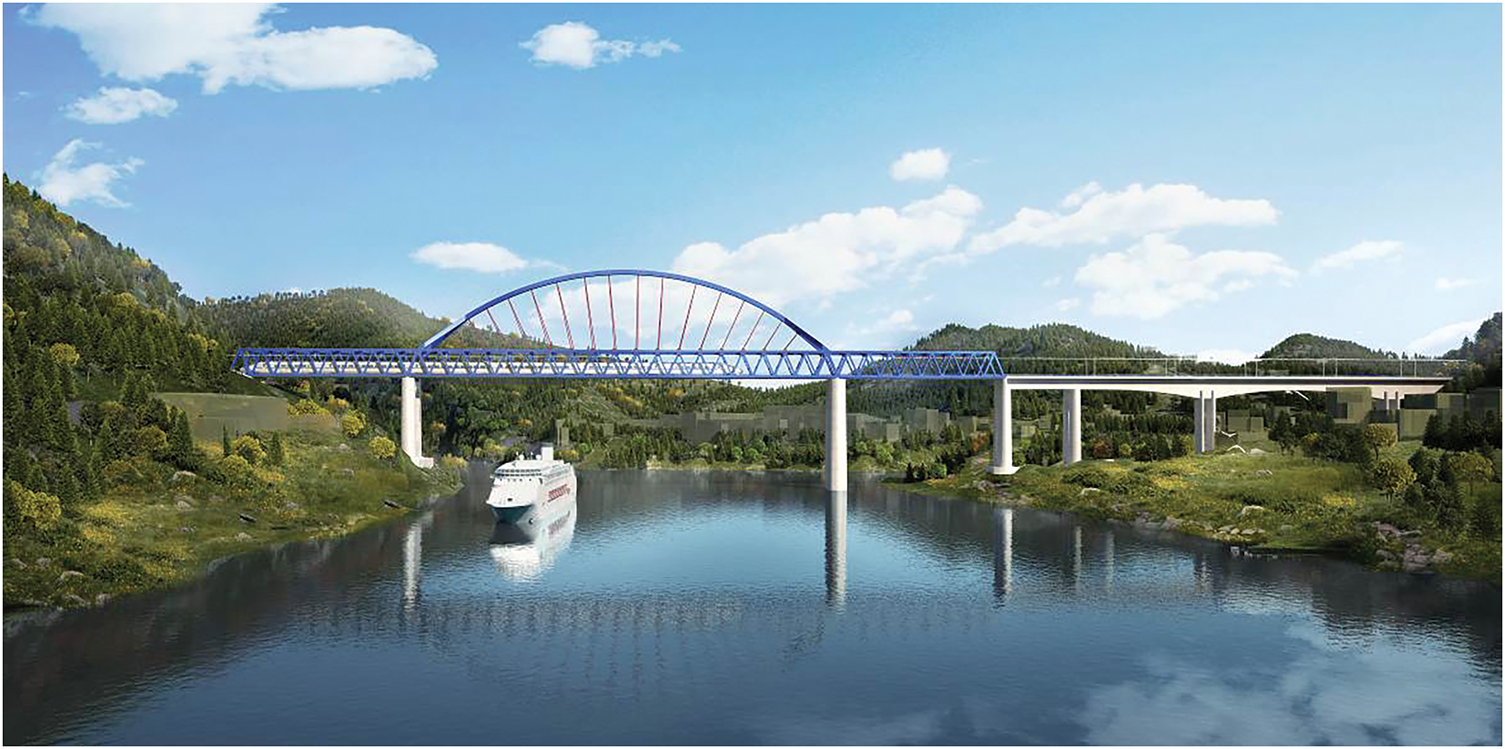
Figure 1: Project rendering of Qingshuiping Bridge
The deck structure is based on an orthotropic plate system, comprising a 16 mm thick steel deck plate, U-shaped longitudinal ribs (with a center-to-center distance of 600 mm, top width of 300 mm, height of 280 mm, and plate thickness of 8 mm), and inverted T-shaped longitudinal beams (with a web height of 500 mm and flange width of 240 mm). Strict design requirements have been established to control the flatness tolerance of the deck plate, with a limit of ±1.5 mm/m, to ensure compatibility with the operational demands of high-speed trains traveling at 350 km/h.
2.1 Finite Element Model Development
In order to conduct a detailed structural analysis of the Qingshuiping Bridge, a comprehensive finite element model was developed using the Midas Civil platform. The model incorporates refined representations of the bridge’s key components to accurately capture their behavior under various loading conditions.
The bridge deck was modeled using shell elements to precisely characterize both in-plane and out-of-plane stiffness properties, as shown in Fig. 2. Longitudinal ribs, transverse beams, and the main truss were modeled with beam elements, with closed-section parameters defined to accurately reflect the torsional resistance of the U-rib.
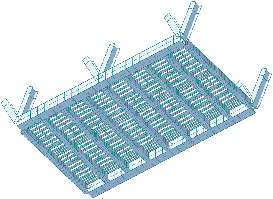
Figure 2: Finite element model between two sections
In the basic fundamental configuration, the lower chord members are configured with box-section beams reinforced with ribs, featuring a height of 1400 mm and a width of 1000 mm. The deck system is comprised of the deck plate, longitudinal and transverse beams, and longitudinal ribs. The deck plate dimensions are specified as 12,912 mm in length and 16 mm in thickness. Positioned beneath the rail tracks, the longitudinal beams are modeled with inverted T-shaped cross-sections, characterized by a web measuring 484 mm in height by 12 mm in thickness and a lower flange measuring 240 mm in width by 16 mm in thickness. Both node and intermediate transverse beams are also modeled with inverted T-shaped cross-sections. The node transverse beams have a web dimension of 1410 mm by 14 mm and a lower flange of 640 mm by 28 mm, while the intermediate transverse beams have a web dimension of 1410 mm by 14 mm and a lower flange of 640 mm by 24 mm. U-ribs are employed, with an upper flange width of 300 mm, a lower flange width of 184 mm, a height of 280 mm, and a uniform thickness of 8 mm. Plate ribs are modeled with dimensions of 200 mm in width by 16 mm in thickness.
During the mesh generation process for the model, a convergence analysis was performed to determine the optimal mesh size. The dimensions of the deck panel elements were set to 50 mm × 50 mm, while the longitudinal rib element length was set to 100 mm. In regions of stress concentration, the mesh was refined to 30 mm × 30 mm to ensure that the computational error was less than 2.5%. The mesh size selection was guided by established practices for similar orthotropic steel bridge deck analyses, ensuring sufficient resolution for stress and deformation predictions. The material properties of steel were taken as follows: elastic modulus of 210 GPa, Poisson’s ratio of 0.3, density of 7850 kg/m3, and yield strength of 345 MPa, in accordance with the Q345qD bridge steel standard. These material parameters and modeling approaches [26] (including element types and mesh convergence criteria) have been widely adopted and validated in previous research on steel bridge decks under static and fatigue loading conditions, demonstrating good agreement with experimental observations.
The selection of U-shaped, inverted T-shaped, and plate stiffeners for comparative analysis was driven by their practical relevance in bridge engineering [27] and specific design considerations for the Qingshuiping Bridge. U-rib has been widely employed in numerous railway orthotropic steel decks in China, exemplified by their application in major projects such as the Nanjing Dashengguan Yangtze River Bridge [28], owing to their favorable structural efficiency. Inverted T-ribs have also found application in significant bridges, notably the Jinan Yellow River Bridge [29], offering an alternative structural solution.
In the model, to investigate the stress characteristics of different types of stiffeners, an equivalent principle was employed to represent the U-rib as a combination of two inverted T-ribs and rectangular ribs, ensuring the equivalence of steel usage, moment of inertia, and centroid location. The specific equivalence principles are as follows:
When the U-rib is equivalent to two inverted T-ribs, the total steel usage and moment of inertia of the inverted T-ribs are made identical to those of the U-rib.
When the U-rib is equivalent to two rectangular ribs, the total steel usage and moment of inertia of the rectangular ribs are also made identical to those of the U-rib.
For the equivalence of one inverted T-rib and one rectangular rib, the web of the ribs is positioned at the center of the U-rib’s top plate.
When the U-rib is equivalent to two inverted T-ribs and two rectangular ribs, the web positions align with the web of the U-rib.
Rectangular ribs were included primarily due to their enhanced constructability compared to the more complex closed sections, potentially simplifying fabrication and installation. Crucially, the comparative study was conducted under the principle of equivalent steel usage (along with moment of inertia and centroid equivalence as detailed earlier), ensuring a fair assessment of the mechanical performance differences attributable solely to the geometric configuration of the stiffeners.
Based on these equivalence principles, five comparative models illustrated in Fig. 3 were established: the double U-rib prototype (Scheme A), one U-rib equivalent to one inverted T-rib (Scheme B), one U-rib equivalent to two inverted T-ribs (Scheme C), one U-rib equivalent to one plate rib (Scheme D), and one U-rib equivalent to two rectangular ribs (Scheme E). The accuracy of these models was verified using mass equivalence (with an error limit of ±1.5%), stiffness equivalence (based on section moment of inertia and bending stiffness), and centroid matching (with a deviation of ≤3 mm), as shown in the following figures.
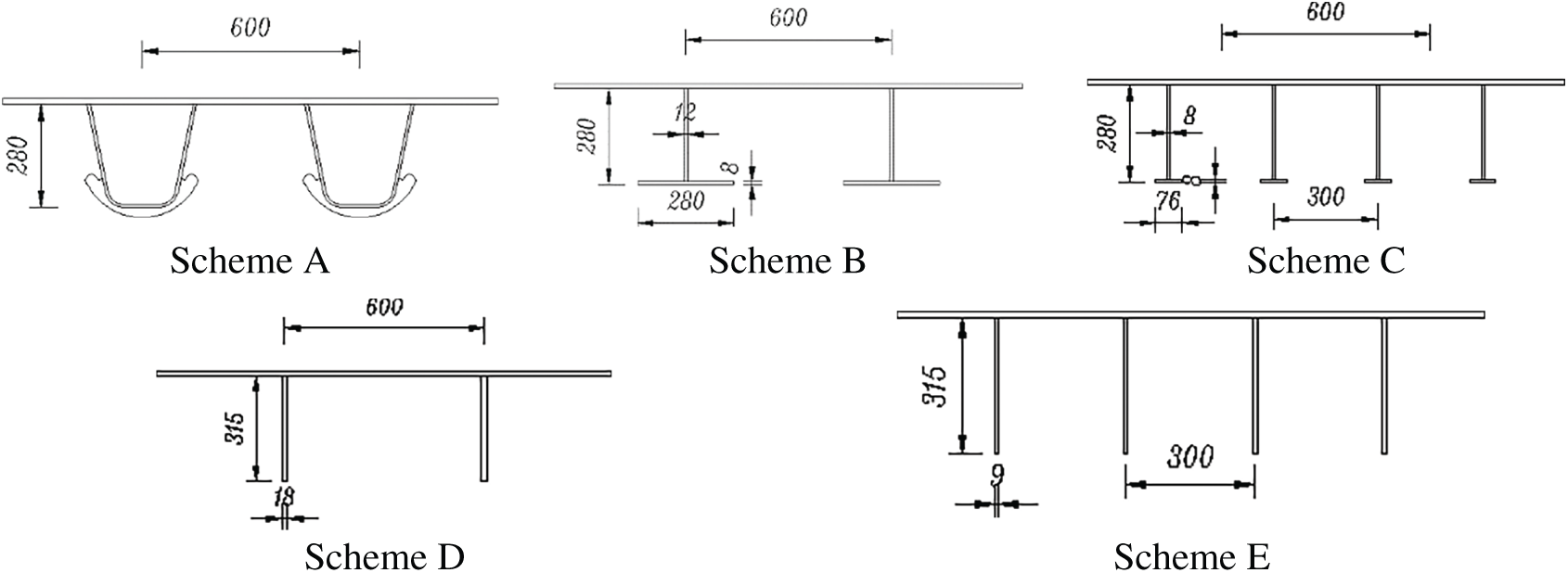
Figure 3: Schematic diagram of different longitudinal rib arrangements (Unit: mm)
In this study, a comparative analysis was conducted on structures with different stiffener configurations, covering 27 parameter combinations, including U-rib thickness (6 to 12 mm) and flange thickness (12 to 24 mm). All models were subjected to the same boundary conditions and Load Cases, as illustrated in Fig. 4.
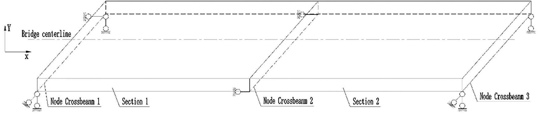
Figure 4: Boundary constraints for the deck system between two sections
The selection of specific loading scenarios was to systematically evaluate the influence of different stiffener configurations on the stiffness, strength, and stability of OSDs under conditions representative of critical demands in high-speed railway applications. OSDs must possess sufficient performance in these aspects to withstand the operational loads of high-speed trains.
Three Load Cases are considered as follows:
Load Case 1: A vertical uniformly distributed load of 200 kN/m is applied across the entire deck plate, which is equivalent to a vertical uniform load of 15.5 kN/m2 on the surface of the bridge deck. The global structural behavior and overall load-bearing capacity under symmetric loading are assessed by this Load Case.
Load Case 2: To investigate the structural response under in-plane transverse eccentricity, a vertical eccentric load is applied to the deck, representing a single-track railway live load of 64 kN/m. The load is applied over a width of 1.5 m, resulting in a vertical uniformly distributed load of 42.7 kN/m2. This condition represents typical live load scenarios for a single-track railway.
load Case 3: A lateral uniformly distributed load is applied to the lower chord of the bridge, which is critical for the deck’s integrity under lateral forces such as wind or centrifugal effects on curves. The load is applied along one side of the lower chord, positioned along the bridge’s centerline, with a magnitude of 1000 kN/m in the transverse direction (perpendicular to the bridge’s longitudinal axis).
3 Influence of Stiffener Configuration on the Deck’s Structural Performance
3.1 Comparison of Deck Deflection Results
In this study, a detailed analysis was conducted on the displacement responses of the deck plate under different stiffener configurations, focusing on the performance differences across various loading conditions. Overall, although the displacement differences of the deck plate under different loading conditions were not significant, the U-rib configuration exhibited clear advantages in controlling local displacements, particularly in terms of vertical and transverse deformations.
As depicted in Fig. 5, the U-rib structure demonstrated smaller local displacements and more uniform deformations, reflecting its superior performance in enhancing the overall stiffness of the deck plate and distributing external loads more effectively. In contrast, the inverted T-shaped and plate rib configurations showed larger local displacements in regions of load concentration, indicating their shortcomings in terms of deformation resistance and stability.
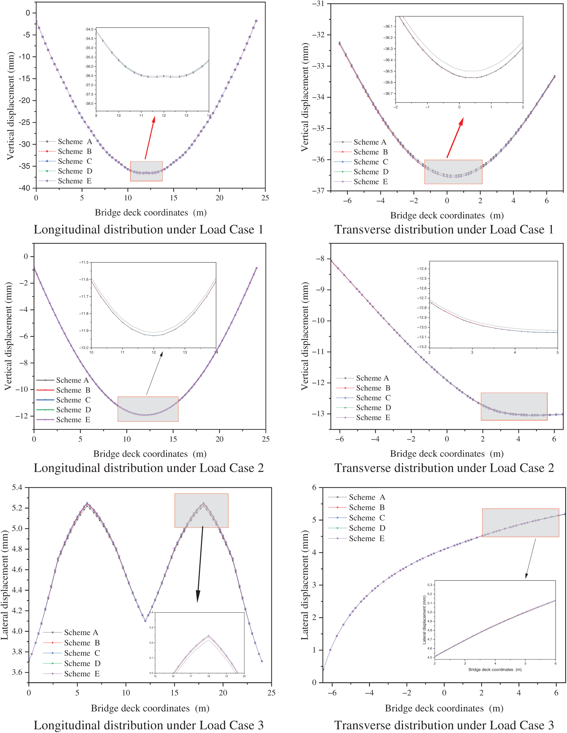
Figure 5: Displacement distribution of the bridge deck under different load cases
Specifically, under Load Case 1 and Load Case 2, the U-rib configuration mitigates vertical deck displacement, particularly in regions with larger spans or concentrated loads. The reduced displacements attest to the U-ribs’ superior flexural rigidity. In terms of transverse displacement, the U-rib also exhibits smaller deformations, especially when subjected to lateral loads. Its superior structural stiffness enables the deck plate to uniformly distribute the loads, reducing local deformations. Conversely, inverted T-ribs and rectangular ribs exhibit larger localized displacements under transverse loading, revealing limitations in transverse deformation control. Under Load Case 3, lateral loading also influences deck deflection distribution. Although U-ribs exhibit smaller transverse deflections than alternative stiffeners, confirming their superior lateral stiffness and deformation resistance, this advantage is less pronounced than under Load Cases 1 and 2. Inverted T-ribs and rectangular ribs show larger deflections, particularly at deck plate edges, indicating reduced stability and heightened susceptibility to localized deformations under transverse loading.
In summary, the U-rib configuration outperforms other stiffener forms in displacement response under different loading conditions, particularly in controlling local deformations and enhancing the deck plate’s resistance to deformation.
3.2 Comparison of Deck Stress Performance
This section analyzes the stress distribution of the deck plate under different loading conditions, from Load Case 1 to Load Case 3. Considering the stress response under different loading conditions is crucial for ensuring the structural safety and durability of the bridge. By simulating the effects of vertical uniformly distributed loads, railway live loads, and lateral loads on the deck plate, this chapter delves into the stress distribution characteristics of the deck under these loading scenarios.
Through a comparison of the longitudinal and transverse stress distributions of the deck plate under various loading conditions, as presented in Fig. 6. This section highlights the advantages of different longitudinal rib designs in controlling stress fluctuations, reducing local stress concentrations, and improving the stability of the deck plate.
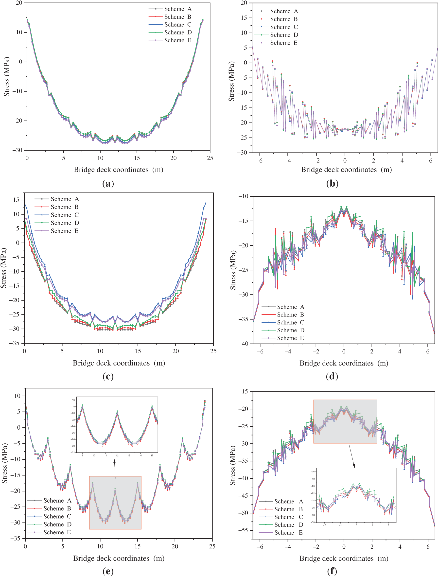
Figure 6: Stress distribution of different components of the deck under Load Case 1. (a) Longitudinal distribution of longitudinal stress at the top of the deck plate center; (b) Transverse distribution of longitudinal stress at the center of the intermediate span; (c) Longitudinal distribution of longitudinal stress at the internal longitudinal beam; (d) Trans-verse distribution of transverse stress at the center of the intermediate span; (e) Longitudinal distribution of trans-verse stress at the top of the deck plate center; (f) Transverse distribution of transverse stress at the top of the deck above the intermediate transverse beam
Under Load Case 1, when subjected to vertical uniformly distributed loading, the stress distribution characteristics of the deck plate are significantly governed by the stiffener configuration. In most regions, the deck plate is compressed, with tensile stresses observed only in small areas above nodes and intermediate transverse girders. At the deck center, longitudinal stress distributions are similar across all stiffener types, particularly above longitudinal girders, where near-uniform stresses are exhibited. However, configurations with two T-ribs and two rectangular-ribs are characterized by marginally lower longitudinal stresses in the deck plate, indicating that the load is more effectively shared and stress concentrations are reduced by these designs. Above the web plate, both longitudinal and transverse stresses show fluctuations. The U-shaped, two T-ribs, and two rectangular ribs schemes exhibit more frequent but smaller fluctuations, suggesting that these designs are more effective at uniformly distributing the load, reducing local stress concentrations, and enhancing the stability of the deck plate. In contrast, the configuration with one T-rib and one rectangular rib shows fewer fluctuations but larger stress amplitudes, indicating that these designs are more prone to generating significant local stress concentrations, which can exacerbate local deformation in the structure.
Overall, superior stress distribution and deformation control are demonstrated by the U-rib, double T-rib, and double rectangular rib configurations. Therefore, these configurations are recommended for use in bridge design to enhance the stiffness and deformation resistance of the bridge. Compared to uniformly distributed loads, vertical eccentric loads exhibit higher non-uniformity, concentrating the load in specific regions, which makes the stress and deformation distribution in the deck plate more complex.
Analysis under Load Case 2 provides critical insights into the deck plate’s stress response and deformation behavior under eccentric loading, particularly regarding potential stress concentration issues during long-term operation. The contributions of different stiffener configurations to deformation resistance, stability, and durability can be assessed through comparative evaluation. This is crucial for ensuring that the bridge can effectively withstand dynamic loads during actual operation, preventing structural damage or performance degradation caused by local deformation and stress concentration.
Under Load Case 2, when subjected to vertical eccentric loading, stress distributions within the deck plate are rendered more complex than under uniform loading (Load Case 1). Significant stress fluctuations are observed in loaded regions due to load non-uniformity, adversely affecting structural stability and long-term performance. Analysis of stiffener configuration impacts reveals that the U-rib design demonstrates superior performance under eccentric loading. Although exhibiting relatively uniform stress distribution in some regions, Schemes C and E show larger stress fluctuations in the loading area. These fluctuations may lead to local stress concentrations, reducing the deck plate’s resistance to deformation and affecting its long-term performance.
Longitudinal stress distributions at the deck plate above internal longitudinal girders (Fig. 7c, d) are further analyzed. Under eccentric loading, the U-rib configuration maintains relatively smooth stress profiles, whereas other configurations display significant fluctuations. This indicates that local stress concentrations are effectively mitigated by U-ribs, enhancing stability and durability. Conversely, configurations with larger stress fluctuations may experience fatigue damage or cracking under sustained loading, thereby reducing structural durability. Compared to vertical loads, lateral loads exert more localized effects, potentially causing substantial transverse deformations and stress concentrations. Performance evaluation under Load Case 3 enables a deeper understanding of stiffener behavior under transverse loading, particularly in terms of their ability to control stress fluctuations and reduce local stress concentrations. This calculation can reveal the differences in the performance of various design schemes in resisting lateral loads, providing a scientific basis to help select the optimal structural configuration.
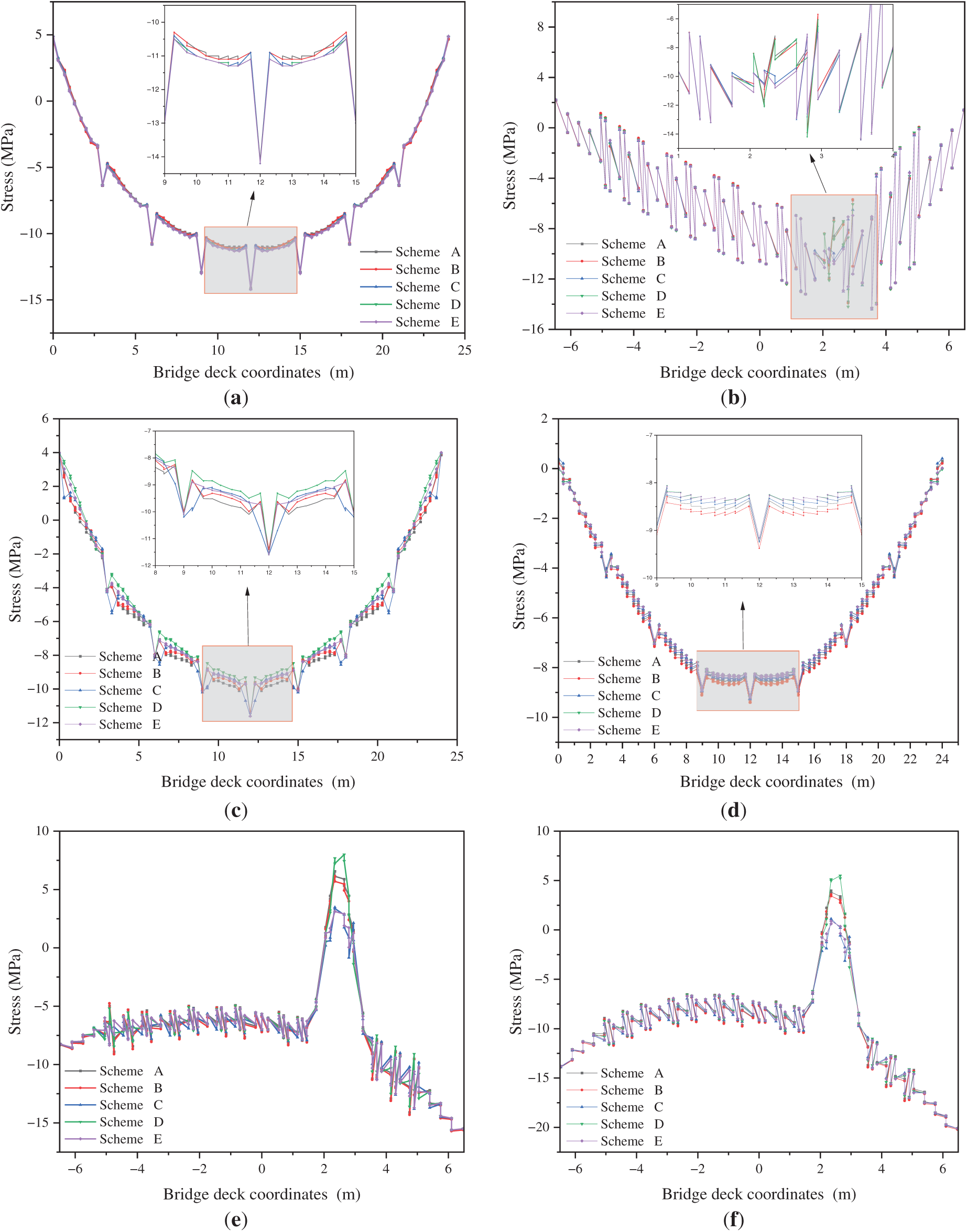
Figure 7: Stress distribution of different components of the deck under Load Case 2. (a) Longitudinal distribution of longitudinal stress at the top of the deck plate centerline; (b) Transverse distribution of longitudinal stress at the top of the deck plate at the center of the intermediate span; (c) Longitudinal distribution of longitudinal stress at the top of the deck plate above the internal longitudinal beam; (d) Longitudinal distribution of transverse stress at the top of the deck plate centerline; (e) Transverse distribution of transverse stress at the top of the deck plate at the center of the intermediate span; (f) Transverse distribution of transverse stress at the top of the deck plate above the intermediate transverse beam
From the analysis of Load Case 3, it is evident that the different stiffener configurations have a significant impact on the stress distribution of the deck plate under lateral loads. In Fig. 8, the U-rib configuration exhibits a more stable stress distribution in both the longitudinal and transverse directions compared to the other configurations. This indicates that the U-rib design can more effectively distribute lateral loads, reduce stress concentrations caused by the load, and enhance the overall stability and deformation resistance of the bridge. In contrast, other configurations, such as the combination of T-ribs and rectangular ribs, show larger stress fluctuations under lateral loading, particularly in regions with concentrated loads, leading to local stress concentrations that could impact the long-term durability of the bridge.
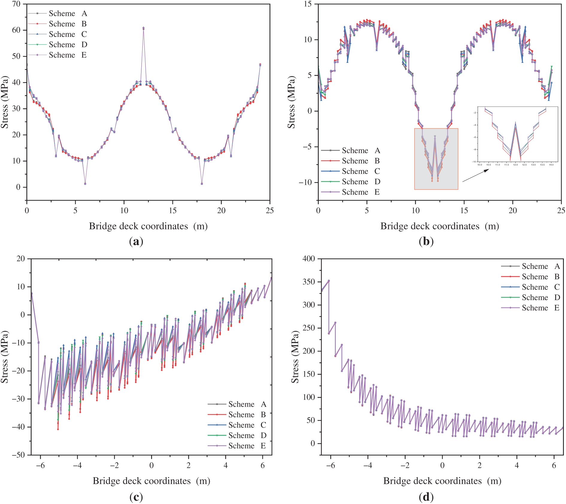
Figure 8: Stress distribution of different components of the deck under Load Case 3. (a) Longitudinal distribution of longitudinal stress on the top of the deck plate centerline; (b) Longitudinal distribution of transverse stress on the top of the deck plate centerline; (c) Transverse distribution of transverse stress at the top of the deck plate above the intermediate transverse beam; (d) Transverse distribution of longitudinal stress at the top of the deck plate above the intermediate transverse beam
In summary, the U-rib design demonstrates a clear advantage over other configurations when subjected to lateral loads. Its smaller stress fluctuation amplitude and more uniform stress distribution indicate that the U-shaped configuration can effectively distribute loads, reduce local stress concentrations, and improve the deformation resistance and durability of the bridge. Therefore, the U-rib design is recommended for use in deck plate design to enhance the long-term stability and service life of the bridge.
3.3 Comparison of Stability Performance
This section presents a stability analysis of the two-section orthotropic steel deck structures with different longitudinal rib configurations (U-shaped, plate rib, and inverted T-rib) under three loading conditions. Table 1 shows the stability coefficients and the unstable components for the different longitudinal rib configurations under the three typical loading conditions. For ease of comparison, a normalized stability coefficient is defined as the ratio of each configuration’s stability coefficient to that of Scheme 1.
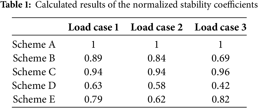
Table 1 presents the calculated normalized stability coefficients for five deck stiffener configurations under three distinct loading conditions. Under Load Case 1, the U-rib design (Scheme A) achieves the highest normalized stability coefficient of 1.00, indicating optimal structural stability. Instability was primarily localized in the longitudinal ribs between internal longitudinal beams and the adjacent deck plate, particularly within small sectional areas flanking intermediate transverse beams. The superior performance of the U-rib is attributed to its enhanced rigidity and load-bearing capacity, which effectively mitigates local buckling and improves overall deck stability.
Under Load Case 2, the U-rib maintains its performance advantage with a coefficient of 0.89, exceeding all alternatives (Scheme B: 0.84; Scheme C: 0.94; Scheme D: 0.58; Scheme E: 0.62). Instability regions were concentrated within longitudinal ribs and the deck plate above the loaded side, again emphasizing vulnerability near intermediate transverse beams. In contrast, rectangular (Scheme B) and inverted T-shaped stiffeners (Scheme D) exhibited notably lower coefficients (0.84 and 0.58, respectively) and more extensive unstable regions, suggesting increased susceptibility to deformation or failure under eccentric loading.
For Load Case 3, the U-rib (Scheme A) demonstrates exceptional stability with a coefficient of 1.00, significantly outperforming other schemes (Scheme B: 0.69; Scheme C: 0.96; Scheme D: 0.42; Scheme E: 0.82). Instability predominantly occurred in the web plate of the lower chord proximal to end transverse beams on the loaded side, especially at load-application boundaries. The markedly lower coefficients of rectangular (Scheme B, 0.69) and inverted T-shaped stiffeners (Scheme D, 0.42) highlight their inferior resistance to lateral deformation. The U-shaped configuration’s closed cross-section provides superior torsional stiffness and constraint, effectively preventing local instability induced by lateral loads.
Collectively, the U-rib demonstrates stability coefficients 11%–138% higher than alternative designs across loading conditions, peaking at 138% superiority under Load Case 3. This consistent quantitative advantage underscores its efficacy in enhancing global deck stability by suppressing localized buckling mechanisms.
4 Study on the Optimization of U-Rib Design Parameters
This section primarily focuses on analyzing the effects of varying U-rib design parameters (such as thickness, rib height, and flange thickness) on the mechanical properties and stability of the orthotropic steel deck structure under different loading conditions. The aim is to provide an optimized design solution for steel deck structures.
The geometric parameter ranges considered in this part were determined based on a statistical survey of relevant parameters observed in various types of railway orthotropic steel deck bridges constructed domestically. The flange thickness typically ranges from 12 to 24 mm, with 16 mm being the most commonly used. The thickness of the U-ribs usually ranges from 6 to 10 mm, with 6 and 8 mm being the most frequently used.
4.1 Impact of U-Rib Thickness on the Mechanical Performance and Stability of Orthotropic Steel Deck Structures
This part maintains all other conditions of the orthotropic steel deck constant (with a flange thickness of 16 mm) and adjusts the U-rib thickness to different values (4, 6, 8, 10, and 12 mm). Corresponding finite element models are established, and a systematic comparison is made to analyze the mechanical performance and stability of the orthotropic steel deck under Load Case 1 (when the deck is subjected to a vertical uniformly distributed load) for different U-rib thicknesses. The stress and deflection variations of the deck system components under Load Case 1 are shown in Figs. 9 and 10.
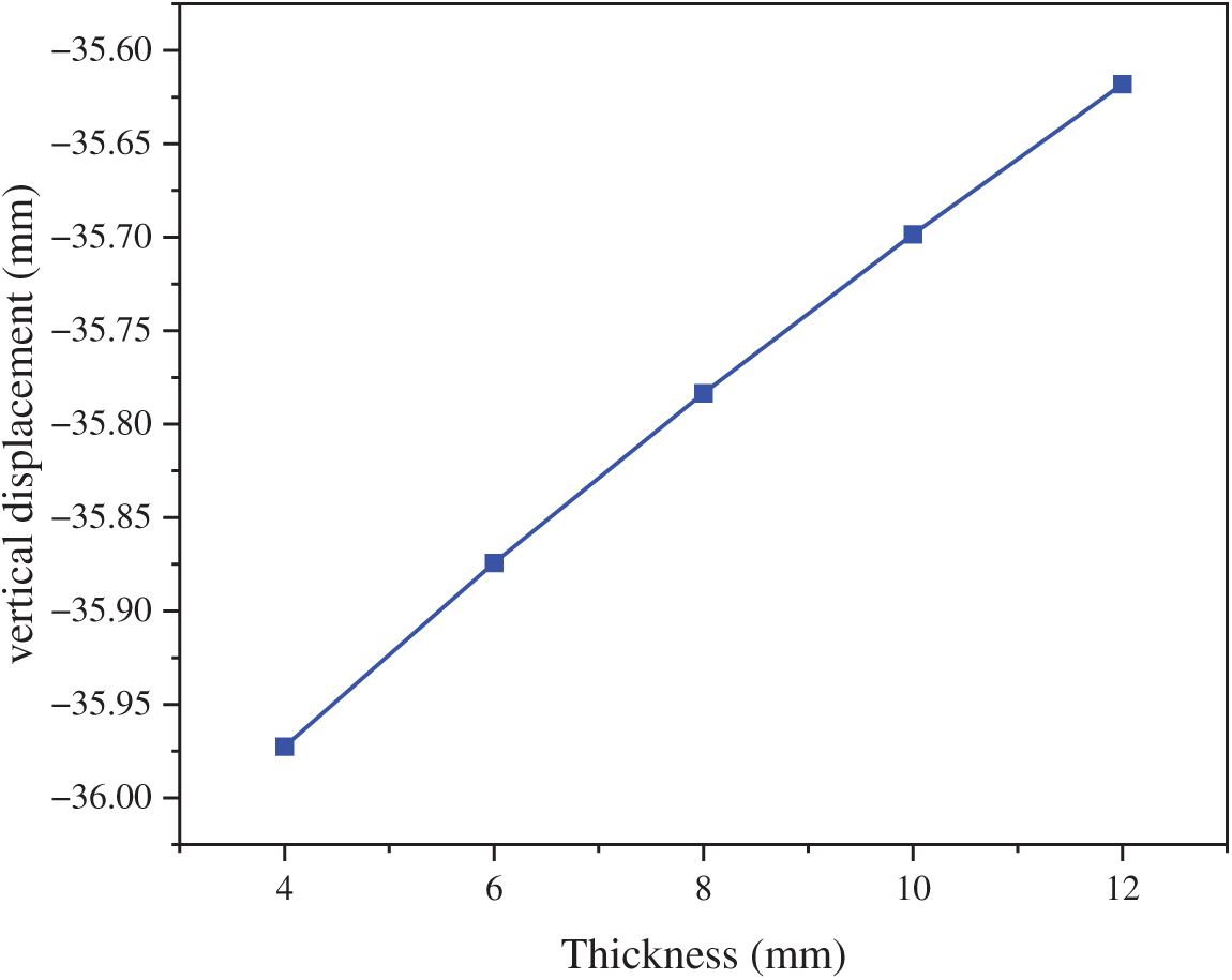
Figure 9: Vertical deflection curve at the center of the intermediate span of the deck plate
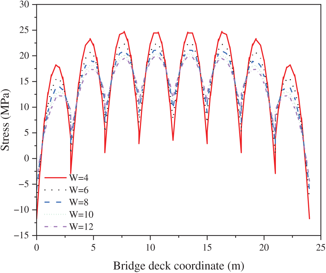
Figure 10: Longitudinal stress at the bottom plate of the U-rib’s lower flange
Parametric analysis reveals that while U-rib thickness variations minimally influence deck plate vertical displacement under constant flange thickness, they significantly modulate longitudinal stress distributions. The most substantial stress reduction occurs within the 4–6 mm thickness range, where a 2 mm increase yields a pronounced 10% decrease in longitudinal stress at critical locations, equating to approximately 3% reduction per 1 mm thickness increment, demonstrating optimal stress-reduction efficiency. Beyond this threshold, the efficacy diminishes progressively: a 6% reduction occurs at 6–8 mm, declining to 4% at 8–10 mm and further to 3% at 10–12 mm. This nonlinear relationship indicates that stiffness enhancement delivers significant stress mitigation (≤6 mm) but transitions to marginal returns at greater thicknesses (≥8 mm), where further increases yield negligible structural benefits.
The normalized stability coefficient curves of the deck system under three loading conditions are presented in Fig. 11. With the flange thickness held at 16 mm, the stability coefficient of the deck system gradually increases as the U-rib thickness increases. Notably, when the U-rib thickness increases from 4 to 6 mm, a significant increase in the stability coefficient is observed. However, as the U-rib thickness further increases, the rate of increase in the stability coefficient gradually diminishes, indicating that at larger U-rib thicknesses, the improvement in structural stability levels off. Therefore, selecting an appropriate U-rib thickness is crucial for enhancing the stability of the deck system, as excessively large thickness increases may lead to diminishing returns. In optimizing the design, it is essential to consider the load types and structural requirements comprehensively.
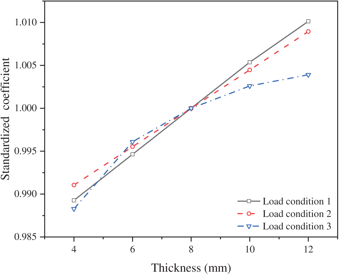
Figure 11: Normalized stability coefficient under different loading conditions
4.2 Impact of Flange Thickness on the Mechanical Performance and Stability of Orthotropic Steel Deck Structures
In this study, considering the impact of flange thickness on the mechanical performance of orthotropic steel decks, the U-rib thickness of 8 mm and U-rib height of 280 mm were maintained. The flange thickness was varied to 12, 14, 16, 18, and 20 mm, and different finite element models were established under three loading conditions for comparative analysis. The following analysis is based on the performance under Load Case 1 and covers the distribution of vertical deflection, longitudinal stress, and transverse stress in the deck plate.
Fig. 12 shows the transverse distribution of the vertical displacement at the center of the deck plate under Load Case 1. A noticeable reduction in vertical displacement is observed as flange thickness increases, demonstrating that deck plate stiffness is improved and vertical deformation is effectively suppressed under vertical loading. The most significant displacement reduction is achieved when the thickness is increased from 12 to 14 mm. For thicker plates (16, 18, and 20 mm), the reduction rate gradually decreases, indicating that the influence of flange thickness on vertical deflection is diminished.
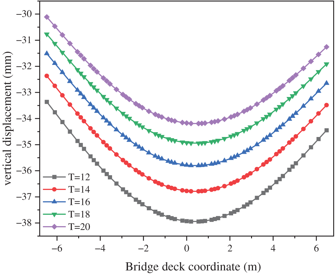
Figure 12: Transverse distribution of vertical displacement
Fig. 13 presents the longitudinal stress distribution of the U-rib upper and lower flanges under varied flange thicknesses. A progressive decrease in longitudinal stress is observed in both flange thickness increases, confirming that structural stiffness is enhanced and flange stress concentrations are reduced. Critically, stress reduction in the upper flange (Fig. 13a) demonstrates significantly higher sensitivity to deck plate thickness changes compared to the lower flange (Fig. 13b), with approximately 1.5 times greater stress reduction magnitude when the thickness is increased from 12 to 20 mm.
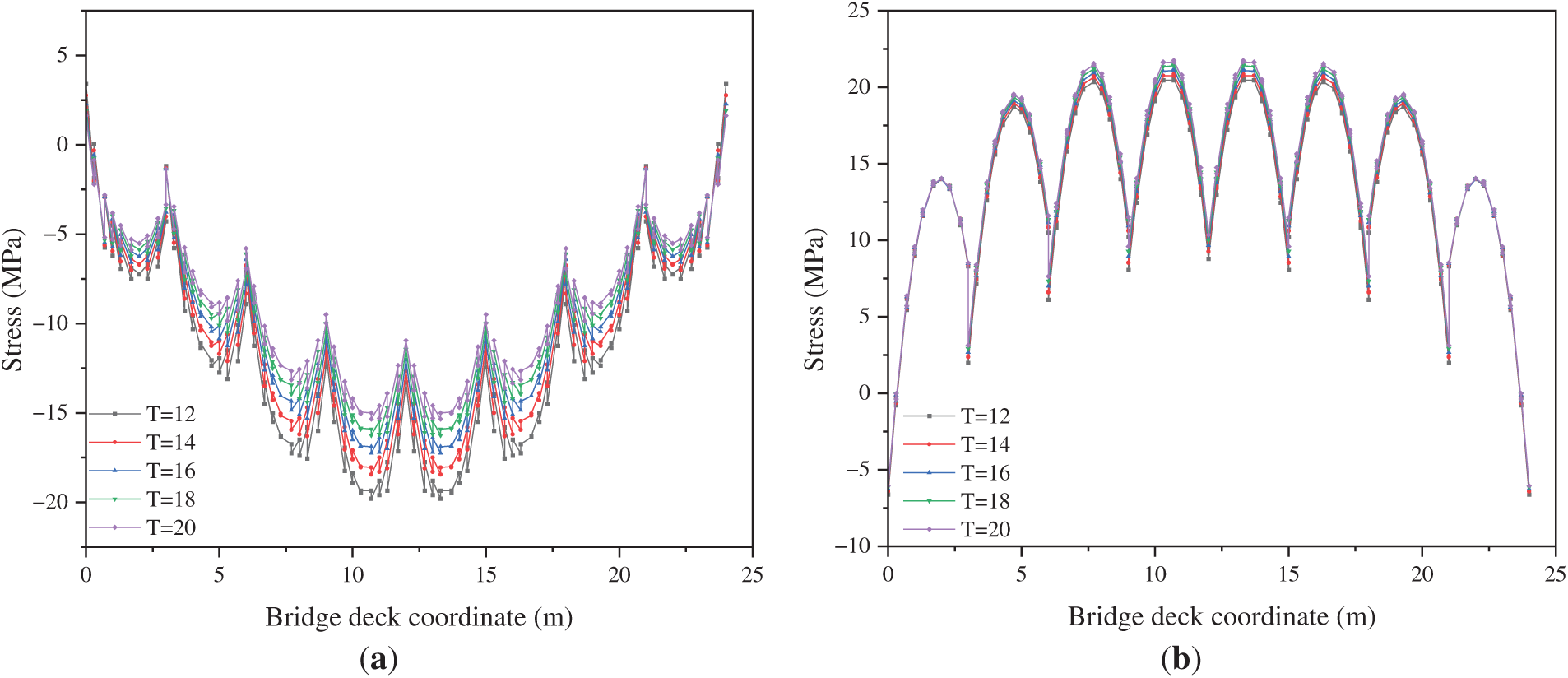
Figure 13: Longitudinal distribution of longitudinal stress in the U-rib. (a) Upper flanges of the U-rib; (b) Lower flanges of the U-rib
In addition, Fig. 14 shows the transverse distribution of longitudinal stress at the top of the center deck plate and the center of the upper flange of the intermediate transverse beam, respectively. As the deck plate thickness increases, both the longitudinal and transverse stress distributions show a decreasing trend. This indicates that a thicker deck plate effectively improves the lateral stiffness of the structure, reducing the stress under lateral loading and preventing stress concentration. In summary, increasing the deck plate thickness can effectively improve the distribution of both longitudinal and transverse stresses, enhancing the stability of the deck system, particularly when the thickness is increased in the early stages, where the improvement is most significant.
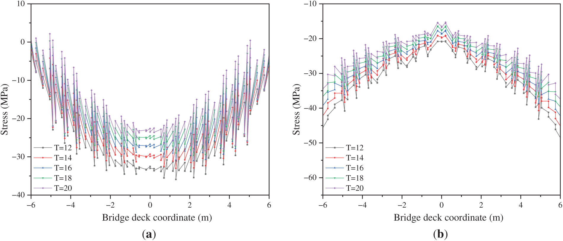
Figure 14: Transverse stress distribution of different components. (a) Top of the center deck plate; (b) Center of the intermediate transverse beam
The relationship between normalized stability coefficients and deck flange thickness under three loading conditions is illustrated in Fig. 15. An increasing trend in normalized stability coefficients is observed across all loading conditions as flange thickness increases, confirming that structural stability is enhanced by thicker flanges. Specifically, when thickness rises from 12 to 20 mm, stability coefficients exhibit progressive improvement, demonstrating that increased plate thickness improves load resistance and structural stiffness.
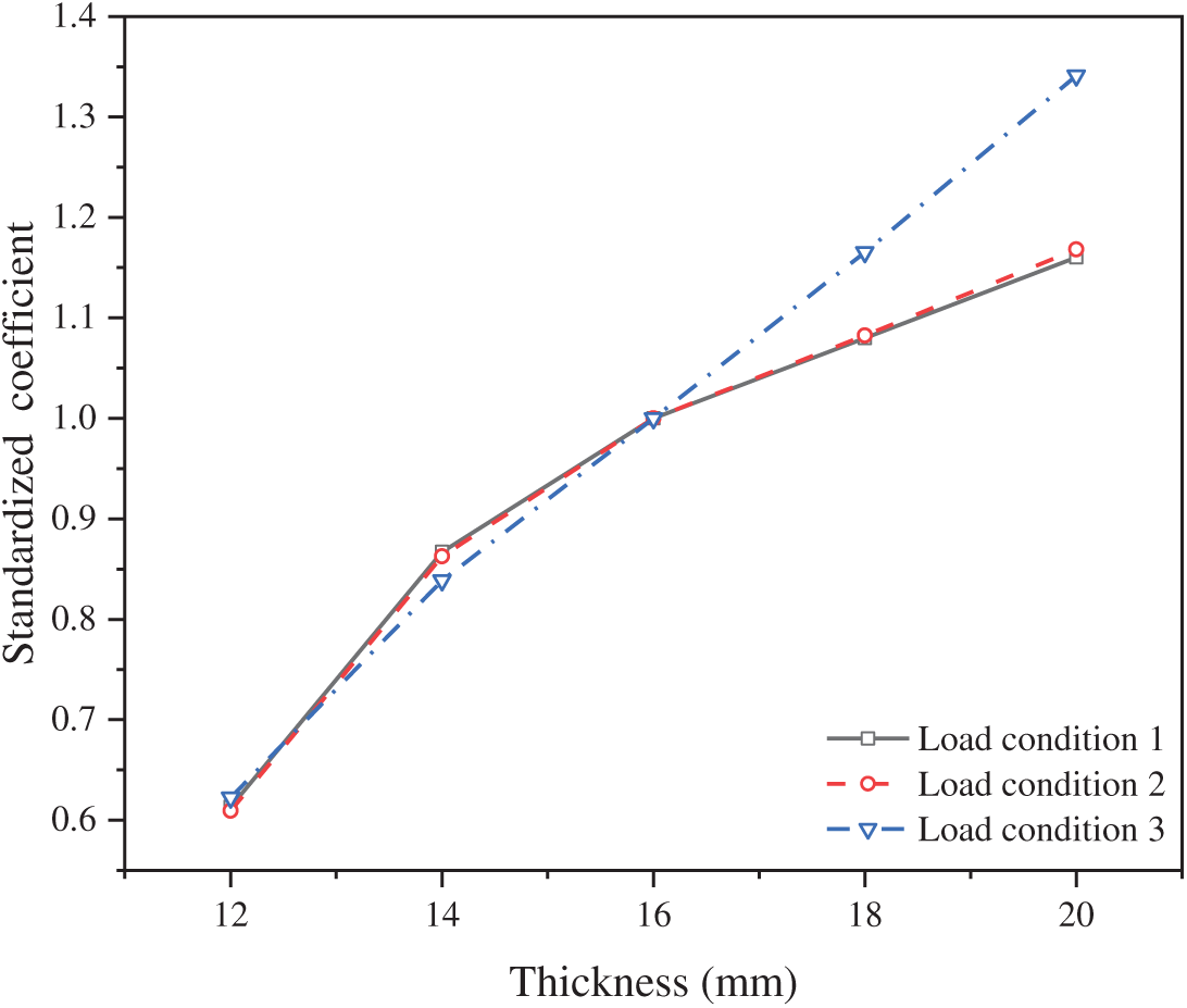
Figure 15: Normalized stability coefficient under different loading conditions
Quantitative analysis reveals distinct enhancement rates across loading conditions: under Load Cases 1 and 2, stability coefficients increase by 41.4% (12 to 16 mm), 15.3% (16 to 20 mm), 7.9% (20 to 24 mm), and 7.4% (24 to 28 mm) for successive 4-mm thickness increments; corresponding increases for Load Case3 measure 34.8%, 19.2%, 16.5%, and 15.0% over the same thickness intervals.
It is worth noting that the most significant stability improvements occur below 16 mm thickness. Beyond this threshold, substantially diminished returns are observed—enhancement rates decrease by 80% for Load Cases 1–2 and 57% for Load Case 3 when comparing initial and final increments. This nonlinear response indicates that stability gains plateau above 16 mm thickness. Consequently, a flange thickness of 16 mm is identified as the optimal design parameter, balancing maximal stability enhancement with material efficiency across all loading conditions.
This study comprehensively evaluated the mechanical performance of orthotropic steel decks (OSDs) employing various longitudinal stiffener configurations (U-shaped, rectangular, T-shaped) under critical loading conditions (vertical uniform, vertical eccentric, lateral uniform). Key findings and their implications are summarized as follows:
While displacement and stress levels exhibited negligible variation across stiffener types under the applied loads, U-rib demonstrated distinct stability advantages. Their closed-section geometry imparted significantly higher torsional rigidity, resulting in up to 138% greater stability coefficients compared to open-section alternatives (rectangular, T-rib) under lateral loading conditions.
Increasing U-rib thickness minimally influenced overall deck displacement; however, longitudinal stresses in both the deck plate and the U-rib bottom flange decreased, though the stress reduction rate diminished considerably beyond a threshold of 6 mm. Similarly, stability coefficients under vertical and eccentric loads increased with thickness, but the rate of improvement slowed significantly beyond 6 mm, while lateral load stability was largely unaffected by thickness variations.
Increasing flange thickness reduced deck plate displacement and longitudinal stress, while U-rib bottom flange stress remained relatively stable. The most pronounced reductions in displacement occurred within the 12–16 mm range. Beyond 16 mm, further increases yielded only marginal improvements in both displacement and stress reduction. Stability coefficients increased across loading conditions, but the rate of gain markedly slowed beyond 18 mm.
The parametric analysis reveals clear thresholds for optimizing structural efficiency. U-rib thicknesses exceeding 6 mm and deck flange thicknesses beyond 16 mm provide diminishing returns in performance enhancement relative to the associated increases in material usage and fabrication complexity. Consequently, targeting a U-rib thickness of approximately 6 mm and limiting the deck flange thickness to 16 mm represents a structurally effective and materially economical design strategy, as validated through application in projects like the Qingshuiping Bridge. The inherent stability superiority of U-ribs confirms their status as the preferred solution for bending-dominant bridge decks under typical vertical loading regimes. Future work should extend this framework to incorporate axial-flexural interactions relevant to cable-stayed or suspension bridges.
Acknowledgement: I am sincerely grateful to the members of my thesis committee for their constructive feedback, critical comments, and valuable advice during the proposal defense and final examination.
Funding Statement: This study was financially supported by the Chongqing Municipal Talent Plan Project (cstc2024ycjh-bgzxm0186).
Author Contributions: The authors confirm their contribution to the paper as follows: Pinyi Zhao conceptualized the study, developed the methodology, and wrote the original draft. Yu Qin performed formal analysis, conducted investigations, and created visualizations. Bo Wu performed a critical review and editing of the manuscript and managed project planning. Yu Chen provided resources, supervised the project, and acquired funding. Xingyu Chen contributed to manuscript writing, review, and editing. Jinsheng Wen participated in manuscript review and editing. All authors reviewed the results and approved the final version of the manuscript.
Availability of Data and Materials: Not applicable.
Ethics Approval: Not applicable.
Conflicts of Interest: The authors declare no conflicts of interest to report regarding the present study.
References
1. Buckland P. Four decades of experience with orthotropic decks. In: Proceedings of the 2004 Orthotropic Bridge Conference, ASCE; 2004 Aug 25–27; Sacramento, CA, USA. p. 25–7. [Google Scholar]
2. Connor RJ. Manual for design, construction, and maintenance of orthotropic steel deck bridges. Washington, DC, USA: Federal Highway Administration; 2012. Report No.: FHWA-IF-12-027. [Google Scholar]
3. Cheng XH. Orthotropic steel deck research and technologies-owner’s perspectives. In: Proceedings of 4th Orthotropic Bridge Conference (ASCE); 2015 Sep 21–25; Tianjin, China. p. 564–77. (In Chinese). [Google Scholar]
4. Ye HW, Pan WZ, He JX. Fatigue limit state of orthotropic steel plate and steel fiber reinforced concrete composite bridge deck. Bridge Constr. 2024;54(4):46–52. (In Chinese). doi:10.20051/j.issn.1003-4722.2024.04.007. [Google Scholar] [CrossRef]
5. Wu B, Zhou J, Li S. Combining active and passive wind tunnel tests to determine the aerodynamic admittances of a bridge girder. J Wind Eng Ind Aerodyn. 2022;231:105180. doi:10.1016/j.jweia.2022.105180. [Google Scholar] [CrossRef]
6. Zhang QH, Cui C, Bu YZ. Study on fatigue features of orthotropic decks in steel box girder of Hong Kong-Zhuhai-Macao Bridge. China Civ Eng J. 2014;47(9):110–9. doi:10.15951/j.tmgcxb.2014.09.039. [Google Scholar] [CrossRef]
7. Bu Y, Li M, Wei C. Experimental and analytical studies on flexural behavior of composite bridge decks with orthotropic steel deck and ultra-high-performance concrete (UHPC) slab under negative moment. Eng Struct. 2023;274:115190. doi:10.1016/j.engstruct.2022.115190. [Google Scholar] [CrossRef]
8. Wei C, Zhang Q, Yang Z. Flexural cracking behavior of reinforced UHPC overlay in composite bridge deck with orthotropic steel deck under static and fatigue loads. Eng Struct. 2022;265:114537. doi:10.1016/j.engstruct.2022.114537. [Google Scholar] [CrossRef]
9. Chen R, Miao C. Fatigue performance evaluation for welded details in orthotropic steel deck bridges using multi-scale finite element method. Struct Durab Health Monit. 2020;14(3):205. doi:10.32604/sdhm.2020.08997. [Google Scholar] [CrossRef]
10. Zhuang M, Miao C, Chen R. Load test and fatigue life evaluation for welded details in Taizhou Yangtze River bridge. Struct Durab Health Monit. 2019;13(2):205. doi:10.32604/sdhm.2019.04654. [Google Scholar] [CrossRef]
11. Liu YM, Zhang QH, Zhang P. Study on fatigue life of U-rib butt weld in orthotropic steel bridge deck of Hong Kong-Zhuhai-Macao Bridge. China J Highw Transp. 2016;29(12):25–33. (In Chinese). doi:10.19721/j.cnki.1001-7372.2016.12.004. [Google Scholar] [CrossRef]
12. Wu C, Yuan Y, Jiang X. Fatigue behavior assessment method of the orthotropic steel deck for a self-anchored suspension railway bridge. Procedia Eng. 2016;161:91–6. doi:10.1016/j.proeng.2016.08.503. [Google Scholar] [CrossRef]
13. Liang T, Liji H, Gao L. Fatigue experimental study of a full-scale steel orthotropic deck model. China Civ Eng J. 2014;47(3):112–22. doi:10.15951/j.tmgcxb.2014.03.006. [Google Scholar] [CrossRef]
14. Fu Z, Ji B, Zhang C. Experimental study on the fatigue performance of roof and U-rib welds of orthotropic steel bridge decks. KSCE J Civ Eng. 2018;22(1):270–8. doi:10.1007/s12205-017-1725-0. [Google Scholar] [CrossRef]
15. Yang M, Kainuma S, Jeong Y. Structural behavior of orthotropic steel decks with artificial cracks in longitudinal ribs. J Constr Steel Res. 2018;141:132–44. doi:10.1016/j.jcsr.2017.11.007. [Google Scholar] [CrossRef]
16. Di J, Wang J, Zhou X. Fatigue behavior of rib-to-floor beam junctions with separate inner stiffeners in orthotropic steel bridge decks. J Bridge Eng. 2022;27(5):4022019. doi:10.1061/(ASCE)BE.1943-5592.0001857. [Google Scholar] [CrossRef]
17. Saunders J, Chen Y, Marks JA. Finite-element fatigue analysis of a new rib-to-floor beam connection for orthotropic steel decks. J Bridge Eng. 2021;26(2):4020123. doi:10.1061/(ASCE)BE.1943-5592.0001676. [Google Scholar] [CrossRef]
18. Shang S, Jiang L, Dong Y. Trial design of a truss bridge prefabricated using a rectangular steel tube—ultra-high-performance concrete composite. Appl Sci. 2024;14(23):11244. doi:10.3390/app142311244. [Google Scholar] [CrossRef]
19. Kato K, Hanji T, Tateishi K. Local stress behavior at closed rib to crossbeam connections in orthotropic steel bridge decks. In: Proceedings of the 13th East Asia-Pacific Conference on Structural Engineering and Construction (EASEC-13); 2013 Sep 11–13; Sapporo, Japan. [Google Scholar]
20. Zhang S, Cao Z, Zhang L. Design and construction of a novel steel–UHPC truss pedestrian bridge in Guangdong province, People’s Republic of China. Struct Eng Int. 2025;53:1–9. doi:10.1080/10168664.2025.2468426. [Google Scholar] [CrossRef]
21. Cheng B, Ye X, Cao X. Experimental study on fatigue failure of rib-to-deck welded connections in orthotropic steel bridge decks. Int J Fatigue. 2017;103:157–67. doi:10.1016/j.ijfatigue.2017.05.021. [Google Scholar] [CrossRef]
22. Deng Y, Li A, Feng D. Fatigue reliability assessment for orthotropic steel decks based on long-term strain monitoring. Sensors. 2018;18(1):181. doi:10.3390/s18010181. [Google Scholar] [PubMed] [CrossRef]
23. Zhu JS, Guo YH. Numerical simulation on fatigue crack growth of orthotropic steel highway bridge deck. J Vib Shock. 2014;33(14):40–7. doi:10.13465/j.cnki.jvs.2014.14.008. [Google Scholar] [CrossRef]
24. Aygül M, Al-Emrani M, Urushadze S. Modelling and fatigue life assessment of orthotropic bridge deck details using FEM. Int J Fatigue. 2012;40:129–42. doi:10.1016/j.ijfatigue.2011.12.015. [Google Scholar] [CrossRef]
25. Zhou D, Ye MX, Luo RD. Improved methods for decreasing stresses of concrete slab of large-span through tied-arch composite bridge. J Cent South Univ Technol. 2010;17(3):648–52. doi:10.1007/s11771-010-0535-z. [Google Scholar] [CrossRef]
26. Ye Q, Peng Y, Wang Z. Simulation of restraint device degradation of long-span suspension bridge based on finite element model. Struct Durab Health Monit. 2025;19(4):851–68. doi:10.32604/sdhm.2025.060906. [Google Scholar] [CrossRef]
27. Xiang Z, Zhu Z. Fatigue behavior of orthotropic composite bridge decks without cutout at rib-to-floorbeam intersection. J Constr Steel Res. 2023;201:107596. doi:10.1016/j.jcsr.2022.107596. [Google Scholar] [CrossRef]
28. Wang T, Xiao L, Yue YT. Research on the fatigue and stability of connection between light rail bracket and integral node of the Dashengguan Yangtze River Bridge. Railw Stand Des. 2021;65(5):97–100. (In Chinese). [Google Scholar]
29. Jiang WM. The key techniques for the construction of Jinan Yellow River Bridge on Qingdao-Yinchuan highway [master’s thesis]. Xi’an, China: Chang’an University; 2009. (In Chinese). [Google Scholar]
Cite This Article
 Copyright © 2025 The Author(s). Published by Tech Science Press.
This work is licensed under a Creative Commons Attribution 4.0 International License , which permits unrestricted use, distribution, and reproduction in any medium, provided the original work is properly cited.
 Downloads
 Citation Tools