
 Submit a Paper
 Propose a Special lssue
 Open Access
ARTICLE

Structural Performance Evaluation of Lift-and-Transverse Type Parking Equipment Based on the Synergy of Experiment and Simulation
1 Hebei Special Equipment Supervision and Inspection Research Institute, Shijiazhuang, 050000, China
2 School of Material Science and Engineering, Hebei University of Science and Technology, Shijiazhuang, 050000, China
3 College of Art, Hebei University of Science and Technology, Shijiazhuang, 050000, China
* Corresponding Author: Chuang Meng. Email:
Structural Durability & Health Monitoring 2025, 19(6), 1681-1694. https://doi.org/10.32604/sdhm.2025.068732
Received 05 June 2025; Accepted 13 August 2025; Issue published 17 November 2025
 View Full Text
 Download PDF
Abstract
The lift-and-transverse type parking equipment, with its core advantages such as high space utilization, modular and flexible layout, and intelligent operation, has become an efficient solution to alleviate the urban parking problem. However, existing research still lacks a systematic evaluation of its structural performance, particularly in areas such as the fatigue characteristics of steel frame materials, stress distribution under dynamic loads, and resonance risk analysis. The stress amplitude (S) and fatigue life (N) relationship curve of Q235 steel, the material used in the steel frame of the lift-and-transverse type parking equipment, was obtained through fatigue testing methods. The finite element simulation model of the steel frame structure of the lift-and-transverse type parking equipment was established using ABAQUS simulation software. Through static simulation analysis, the deformation and stress distribution under various operating conditions, including full load, partial load, and no load, was obtained. The fatigue life under full load and partial load was determined through FE-Safe fatigue analysis. Modal analysis was conducted to get the natural frequencies of the steel frame structure at various modes, which were compared with the operating frequency of the equipment to avoid resonance. This paper examines the evaluation methods for the structural performance of lift-and-transverse type parking equipment, providing a reliable research basis for the design and fatigue life analysis of this specialized structure.Keywords
Mechanical parking equipment is characterized by its ability to utilize spatial advantages fully. By increasing the number of parking spaces from a single ground level to multiple levels (such as the second, third, or even more), it can significantly raise the number of parking spots, effectively easing parking difficulties [1]. Among various types of mechanical parking equipment, the lift-and-transverse type, mainly based on a steel frame structure, serves as a key solution to reduce urban static traffic pressure. Its performance evaluation system is closely linked to the reliability and sustainable development of urban parking systems [2]. For this type, the mechanical properties of its steel frame largely determine the safety limits and service life of the equipment. Currently, the scientific basis of this evaluation system has become a major factor limiting industry growth [3]. As the core component of the load-bearing system, the steel frame is susceptible to stress concentration and local buckling under complex conditions such as eccentric loading and impact loads. This paper investigates these issues to explore potential solutions [4].
Scholars from both domestic and international backgrounds have made significant progress in the field of parking equipment performance research; however, the technical approaches employed have shown distinct characteristics. Domestic research has focused on optimizing structural mechanics and developing control systems. For example, Zhang [5] used the dynamic simulation of the lifting system of the three-claw cylindrical underground intelligent garage as the core, and combined static analysis and data post-processing to create a complete analysis process for the garage’s use, examining its structural performance and internal mechanisms during the operation. Liu [6], on the other hand, studied the vertical circulation stereo garage with Creo 2.0 software as the research platform, Pro/Toolkit as the development tool, Visual Studio 2010 as the environment, and SQL Server 2005 as the database system. He researched the parametric design system technology for stereo garages. In terms of intelligence, Yang [7] conducts fuzzy comprehensive evaluation through hierarchical analysis method and improved entropy weight method, and proposes risk control strategies for weak links, and establishes risk prevention and control, monitoring and early warning system. International research emphasizes integrating safety, early warning, and intelligent diagnostic technologies. For example, Keote and Thantawi and Indriyati [8,9] developed an IoT-based intelligent safety parking system, among others. The application of mathematical models greatly improved parking space utilization, system accuracy, and user satisfaction, while also cutting energy consumption. Ai et al. [10] built a mechanical model for an active parking brake system, derived formulas for handbrake force and torque during parking on slopes, and validated the correlation between test bench data and real vehicle data experimentally. This research offers important theoretical support for designing mechanical parking equipment.
Despite extensive research conducted by both domestic and international scholars on the structural performance and intrinsic mechanisms of mechanical parking equipment, most studies have predominantly utilized the ANSYS platform. There is a notable lack of parametric finite element model construction based on ABAQUS/CAE, which limits model flexibility and analysis efficiency. Furthermore, the assessment of the fatigue life of parking equipment remains insufficient, with many studies focusing solely on static strength or modal characteristics. Few systematically integrate tools like FE-safe to quantify damage and life under varying working conditions. This paper focuses on the lift-and-transverse type mechanical parking equipment as the research subject. A parametric finite element model of the steel frame structure is established using the ABAQUS/CAE platform. Through static simulation analysis, we investigate deformation patterns and stress distribution under three typical working conditions: full load, partial load, and no load. The results indicate that the maximum equivalent stress remains below the yield strength of the specified material and that the maximum deformation is within the allowable limits set by the crane design specification GBT/3811—2008. To further analyze the structural integrity, FE-safe fatigue analysis is employed to determine the maximum damage and fatigue life of the steel frame structure under each working condition. Additionally, modal analysis is conducted to identify the first ten natural frequencies, which are then compared to the actual operating frequency range of the equipment. This dynamic analysis rules out the possibility of resonance, providing a solid foundation for structural design evaluation and fatigue life analysis.
2 Fatigue Test and Acquisition of S-N Data
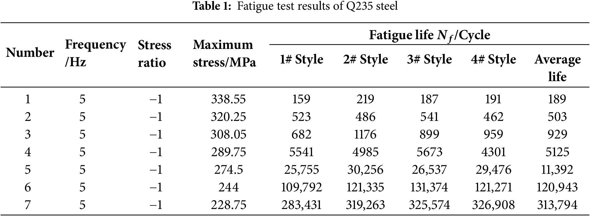
According to the latest fatigue test standards of ASTM E606/E606M-2021, the uniaxial tension and compression fatigue test of Q235 steel was carried out by using the MTS810 material testing machine, with a test temperature of 20°C ± 1°C (room temperature control) and humidity control of 50% ± 5%, to avoid avoiding extreme humidity interference. Standard rod specimens are typically cylindrical, with a diameter ranging from 8 to 15 mm. The number of specimens was 4. Repeated tests were performed to reduce random errors, and all 4 specimens were obtained from the same batch of material. The surface of the specimens must be polished to a roughness of Ra ≤ 0.8 μm to the rods were subjected to annealing treatment (held at 600°C–650°C for 1 h) to eliminate cold working hardening. The surface was cleaned with acetone/ethanol to remove oxides, and the non-testing areas were encapsulated with epoxy resin. The low-cycle fatigue test data for Q235 steel rods are shown in Table 1. The typical form of the relationship curve between stress amplitude (
here, C and m are material constants.
2.2 Acquisition and Correction of S-N Data
Corrections for geometric effects of H-shaped sections need to consider the influence of section geometric parameters and corrections for stress concentration factors. The flange width-to-thickness ratio (b/t), web height-to-thickness ratio (h/t), and length-to-slender ratio (λ) of the H-shaped section significantly affect the local stability and the effective strain distribution using the correction Eq. (2) [12]:
where
The residual tensile stresses in the H-shaped welded section can be up to 30%–50% of the yield strength of the material, and the Goodman’s criterion [14] was used to correct for the effect of average stresses. Where is the Q235 tensile strength.
The residual tensile stress in the H-shaped welded section can reach 30%–50% of the material’s yield strength. The Goodman criterion is employed to correct for the influence of mean stress, where
Based on the low-cycle data, the Basquin parameters were fitted to obtain the fatigue strength coefficient
where
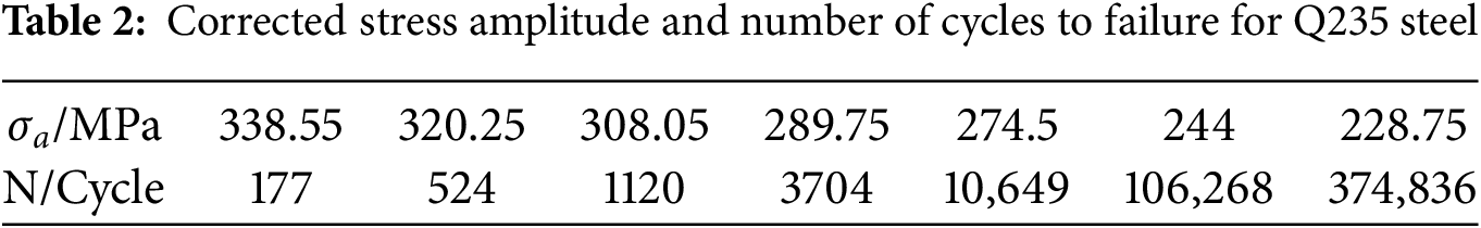
By considering the geometric parameters and stress concentration factor, the low-cycle S-N curve of the rod is transformed into the high-cycle curve of the H-shaped section. The corrected stress amplitude (
3 Finite Element Simulation and Life Prediction
3.1 Steel Frame Structure Modeling
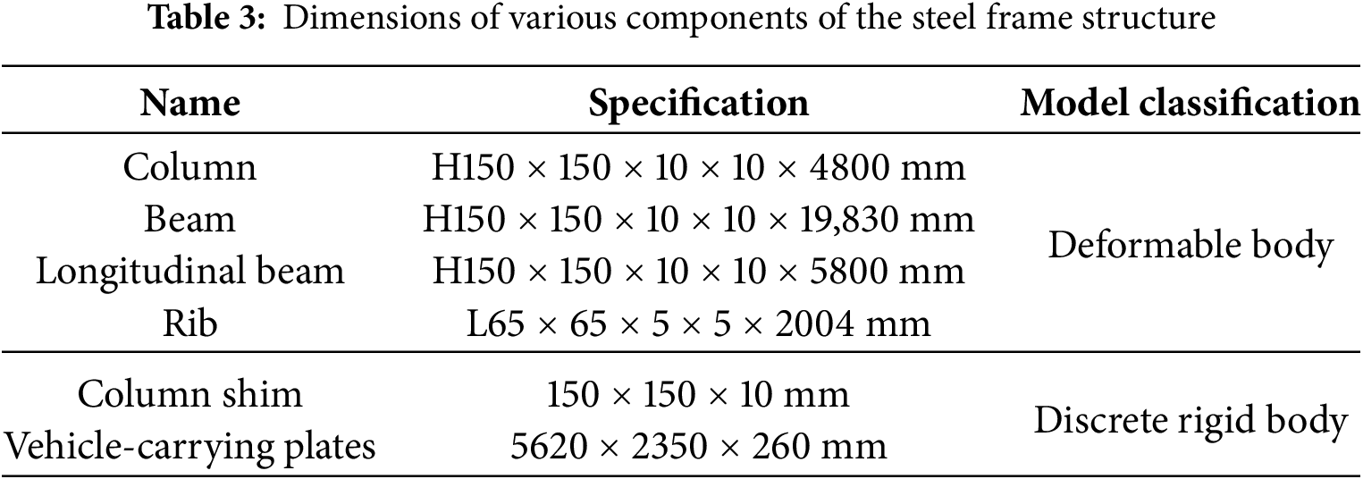
The overall dimensions of the lifting and transferring multi-storey parking garage are 19,980 mm × 6100 mm × 4810 mm. A three-dimensional model was created using Solidworks software and then imported into Abaqus software for analysis. The imported model is shown in Fig. 1. The steel frame structure of this lift-and-transverse type multi-storey parking garage consists of columns, beams, longitudinal beams, vehicle-carrying plates, and other components, with specific dimensions as shown in Table 3. The steel material used for the steel frame is Q235, with an elastic modulus of 200 GPa, a Poisson’s ratio of 0.3, and a density of 7.850 kg/m3. In the boundary condition settings, the bottoms of the eight columns are fully fixed, and the interaction conditions are set as general contact. Loads are applied to the vehicle-carrying plates according to different working conditions, such as full load, partial load, and no load. A dynamic-explicit analysis step is set, and the mesh type is the ten-node quadratic tetrahedral element (C3D10 mesh).
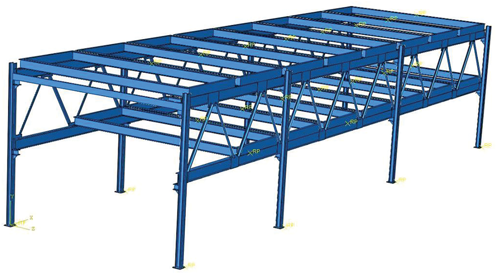
Figure 1: Three-dimensional model of the lift-and-transverse type mechanical parking garage
3.2 Static Analysis under Variable Operating Conditions
When conducting static analysis of the steel frame structure, it is necessary to determine the loads under different operating conditions. The stress conditions under various operating conditions are shown in Table 4. The load distribution under full load and partial load conditions is shown in Fig. 2.
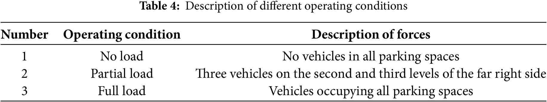
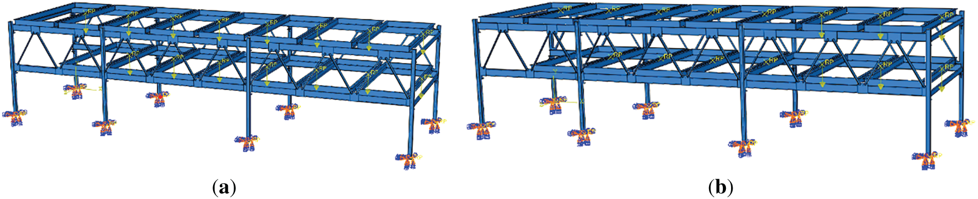
Figure 2: Load distribution under full load and partial load conditions: (a) Full load; (b) Partial load
The stress and displacement distribution diagrams under various operating conditions are shown in the following Figs. 3 and 4:
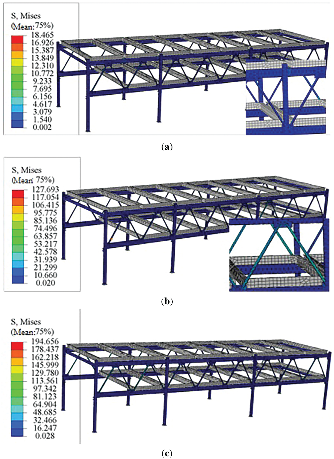
Figure 3: The stress distribution diagrams under various operating conditions: (a) No load; (b) Partial load; (c) Full load
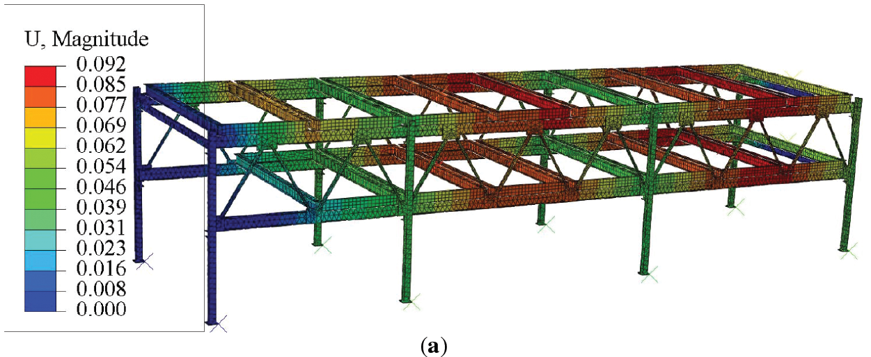
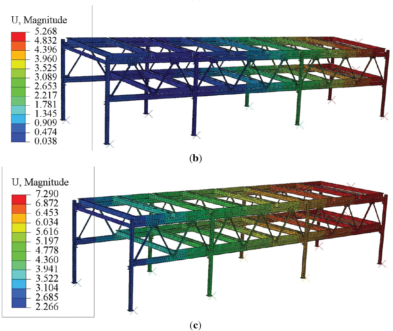
Figure 4: The displacement distribution diagrams under various operating conditions: (a) No load; (b) Partial load; (c) Full load
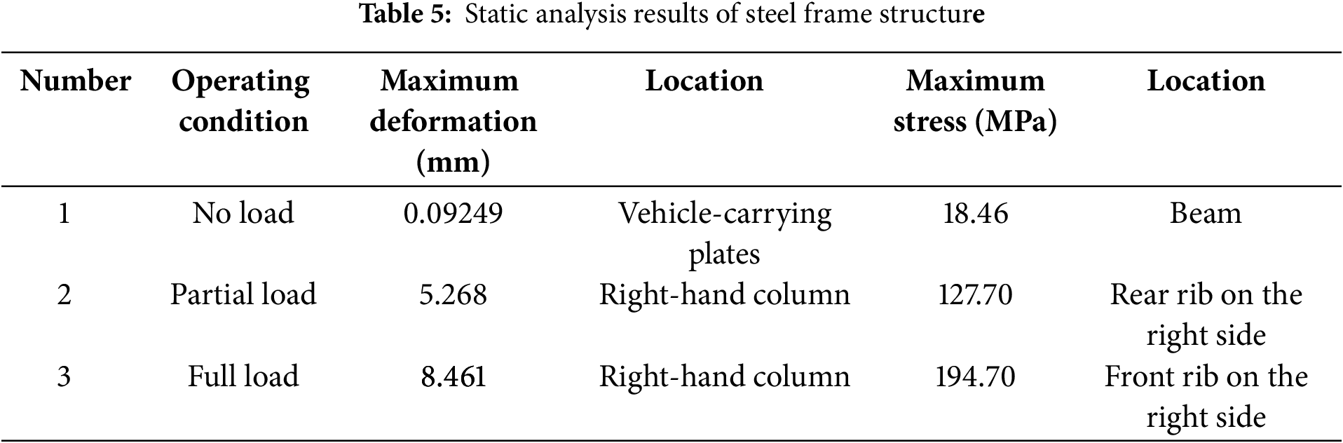
The design standard for the steel frame structure of lifting and translating mechanical parking equipment is typically based on the national standard GB/T 3811—2008 [15]. According to this standard, the relationship between the deflection w and the span S of the steel frame structure of the parking equipment is as follows: For parking equipment with low positioning accuracy, or with an infinitely variable speed control system, or where low speed and low acceleration can achieve acceptable positioning accuracy:
Since the chain drive of the parking equipment operates at a low speed and the positioning accuracy requirements for the lifting process are not high, the maximum deformation occurs under operating condition 3 (full load), as determined from the simulation results obtained using Abaqus software. The maximum deformation is located at the right-hand column, with a value of 8.461 mm, which is less than the allowable value of 4800/500 = 9.6 mm. Therefore, the stiffness of the steel frame structure of the parking equipment meets the requirements (see Table 5).
According to the design specifications, the allowable safety factor
In summary, the stiffness and strength of the steel frame structure of the parking equipment both meet the operational requirements.
FE-safe is a professional fatigue life prediction software based on finite element analysis (FEA), capable of effectively evaluating fatigue damage of structures under alternating loads [16]. Its core strengths lie in its multiaxial fatigue analysis capabilities and efficient integration. It supports multiaxial fatigue models such as the Brown-Miller criterion and critical plane methods, which are suitable for damage calculations under complex stress states [17]. FE-safe can directly read stress results from FEA software like Abaqus and ANSYS (e.g., .odb format files), and after analysis, it outputs fatigue life contour plots, achieving seamless integration from static analysis to fatigue assessment [18].
Based on the static analysis results presented earlier, it is evident that the steel frame structure experiences relatively low stress under the no-load condition, which is significantly different from the stress levels under full-load and partial-load conditions. Given that no damage is anticipated to occur under the no-load condition in the FE-safe fatigue analysis, only the full-load and partial-load conditions are selected for fatigue analysis. The static analysis files for the full-load and partial-load conditions (in .odb format) are imported into the FE-safe software separately. The S-N curve of the material and the mean stress correction method (e.g., the Goodman model) are defined, and the fatigue analysis is conducted to obtain the fatigue life distribution diagrams for the steel frame structure under both full-load and partial-load conditions, as shown in Fig. 5.
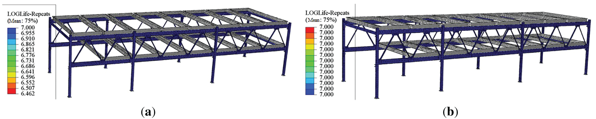
Figure 5: The fatigue life distribution diagrams for the steel frame structure under both full-load and partial-load conditions: (a) Full load; (b) Partial load
The fatigue analysis results indicate that under the full-load condition, the maximum damage of the steel frame structure is 3.45 × 10⁻⁷, with a minimum fatigue life of 106.462 cycles. This critical location is identified at the connection between the beam and the rib. In contrast, no damage is observed under the partial-load condition. Analysis reveals that under the full-load condition, the steel frame structure is subjected to symmetrically distributed loads, which lead to higher alternating stress amplitudes at key nodes and a relatively uniform stress distribution, facilitating the accumulation of fatigue damage. Conversely, under the partial-load condition, although local stress levels may increase, the asymmetric nature of the loading results in a gradient stress distribution. In some regions, the stress levels do not reach the material’s fatigue limit, and the structure may mitigate stress concentration through stiffness redistribution. For instance, the asymmetric loading under partial load may place certain components in a low-stress state, thereby delaying the initiation of fatigue cracks [19].
It is worth noting that this fatigue analysis did not consider the influence of environmental factors on fatigue life, and related experiments show that the fatigue life of Q235 steel decreases significantly with increasing temperature. In a corrosive environment, fatigue life may be shortened by about 10%–20% for every 10°C increase in temperature, depending on the stress level and corrosion time. Therefore, the results of the fatigue analysis above will be due to the influence of temperature, corrosion and other environmental factors and there is a result bias error.
3.4 Modal Analysis of Steel Frame Structure
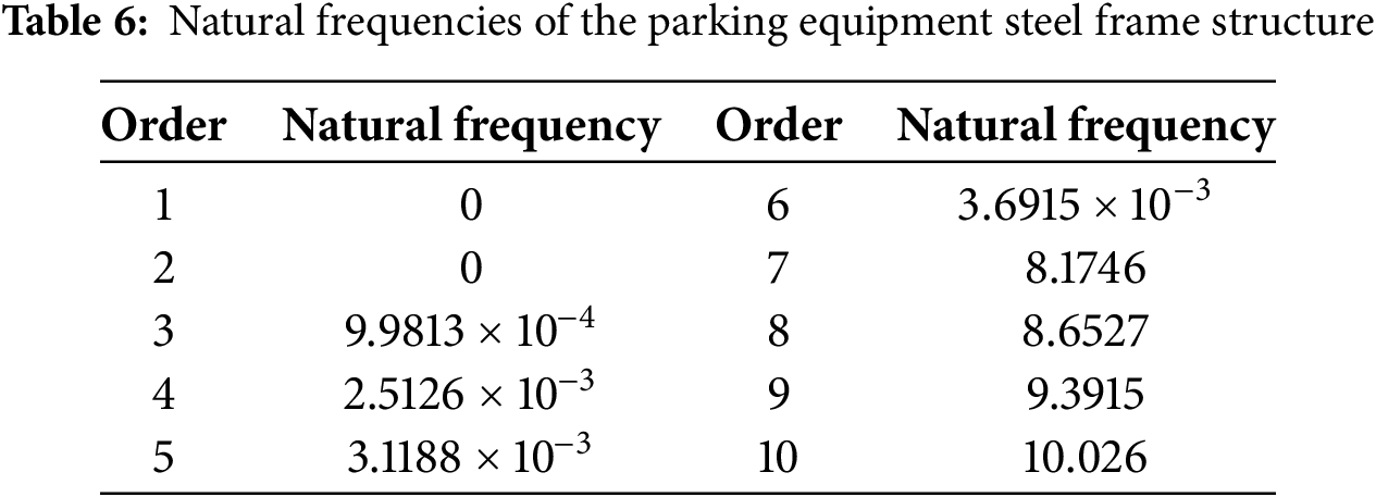
Modal analysis can determine the natural frequencies of the steel frame structure of the parking equipment, which can effectively avoid resonance by steering clear of these natural frequencies [20]. In this section, a 10-mode modal analysis of the parking equipment frame was conducted using Abaqus, obtaining the natural frequencies and mode shape contour plots of the steel frame structure, as shown in Figs. 6–10, with the corresponding frequencies of the modal analysis presented in Table 6.
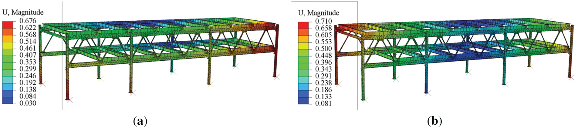
Figure 6: Contour plots of first and second modal deformations: (a) First-order mode; (b) Second-order mode
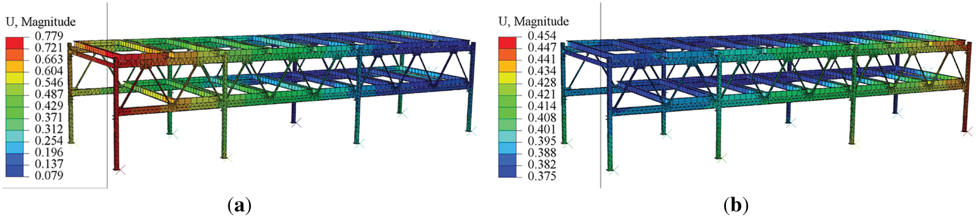
Figure 7: Contour plots of third and fourth modal deformations: (a) Third-order mode; (b) Fourth-order mode
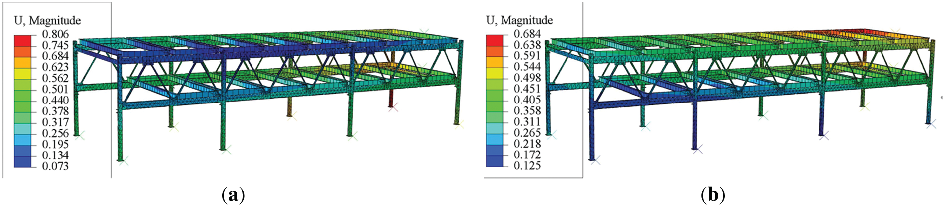
Figure 8: Contour plots of fifth and sixth modal deformations: (a) Fifth-order mode; (b) Sixth-order mode
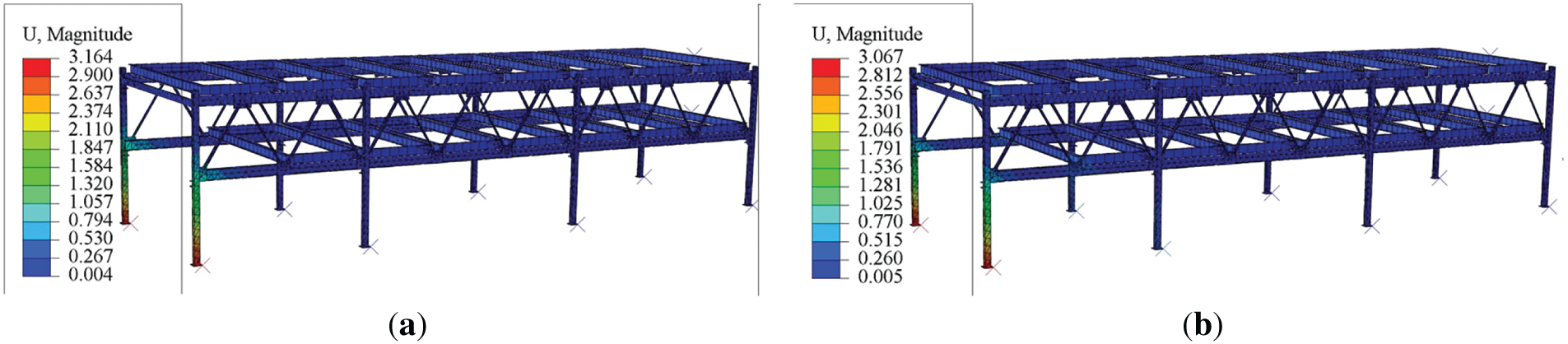
Figure 9: Contour plots of seventh and eighth modal deformations: (a) Seventh-order mode; (b) Eighth-order mode
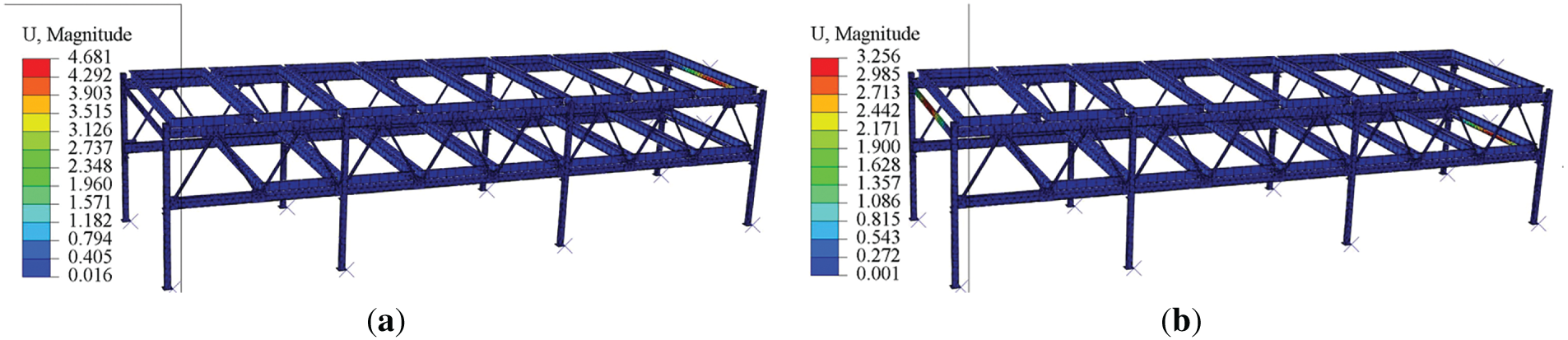
Figure 10: Contour plots of ninth and tenth modal deformations: (a) Ninth-order mode; (b) Tenth-order mode
Resonance can be highly destructive, and external vibration sources can easily excite resonance in parking equipment. To ensure the safe operation of the equipment, it is essential to eliminate relevant vibration sources around the parking equipment [21]. The vibrations generated by the operation of the equipment itself mainly originate from the frequency of the motor vibrations in the lifting and translating mechanisms. The lifting motor, typically used in heavy-load, low-speed scenarios (such as lifting a fully loaded vehicle weighing 2 t), employs a high-reduction-ratio transmission, with a base frequency usually ranging from 12 to 20 Hz. The translating mechanism, which requires a faster response for the translating action, commonly uses a frequency-controlled motor for speed adjustment, with a base frequency typically within the range of 20 to 40 Hz.
From the modal deformation distribution diagrams, it can be observed that the first six natural frequencies of the steel frame structure are very low, approaching zero. The natural frequencies of the 7th to 10th modes range from 8 to 10 Hz. Comparing these natural frequencies with the base frequencies of the lifting and translating motors, it is found that there is a significant difference between the modal analysis natural frequencies and the motor frequencies. Therefore, resonance will not occur during the operation of the parking equipment.
4.1 Static Analysis Verification
To verify the consistency between the stress-strain response of the finite element model under static loads and the actual experimental results, strain gauges were used to obtain the measured stress data of the steel frame under full-load, partial-load, and no-load conditions. These data were then compared with the static simulation results from Solidworks/Abaqus [22,23]. The distribution of strain gauges is shown in Fig. 11, and the specification of the data acquisition equipment used is DH5922D Dynamic Signal Test and Analysis System, and the relative error formula is used for error analysis, and the model is considered to be reliable if the error is ≤10% [24,25]. In the formula,
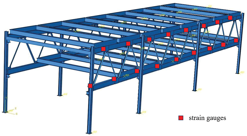
Figure 11: Strain gauges distribution
Under the full-load condition, the maximum stress in the steel frame was concentrated at the connection between the column and the rib. The experimentally measured maximum stress was 205.60 MPa, while the simulation result was 194.70 MPa, yielding a relative error of 5.3%. Under the no-load condition, the overall stress level of the frame was low, with the measured and simulated stress errors generally ≤3%, indicating that the model has high accuracy under low-load conditions. Due to the uneven load distribution, the stress response under the partial-load condition exhibited significant asymmetry. The experimentally measured stress peak on the left-hand column was 138.40 MPa, whereas the simulation result was 127.70 MPa, resulting in an error of 7.7%.
The results of static verification indicate that the finite element model of the steel frame structure, constructed based on Solidworks/Abaqus, exhibits high accuracy under full-load, partial-load, and no-load conditions, with stress errors in critical areas ≤10%, meeting the requirements for engineering reliability [26,27]. Further analysis reveals that the errors primarily stem from the simplification of boundary conditions, local contact nonlinearity, and the dispersion of material parameters. Model refinement driven by experimental data, such as optimizing preload, refining mesh density, and introducing residual stress fields, can significantly enhance the accuracy of predictions.
To verify the reliability of the finite element model in dynamic characteristic analysis, a systematic comparison of the first ten natural frequencies of the steel frame structure of the lifting and translating mechanical parking equipment was conducted [28]. The experimental modal analysis was performed using an impact hammer to excite the structure and accelerometers to capture the vibration signals, obtaining the first ten natural frequencies of the steel frame. The measured natural frequencies ranged from 0.04 to 11.4 Hz. Comparison with the modal simulation results from Abaqus revealed that the frequency errors for each mode were all ≤5%, meeting the engineering accuracy requirements [29,30].
The fatigue test was carried out to establish the relationship curve between the stress amplitude (S) and fatigue life (N) of Q235 steel under low-cycle fatigue conditions. This relationship was subsequently refined to develop an S-N curve applicable to the steel frame structure of lifting and translating mechanical parking equipment. A three-dimensional model of the steel frame structure was created, followed by static simulation analysis under varying operating conditions. The maximum stress recorded under each operating condition was 194.07 MPa, and the maximum displacement measured was 8.461 mm, both of which conform to design code requirements. Fatigue life and maximum damage were evaluated under full-load and partial-load conditions using FE-safe fatigue analysis. Additionally, modal analysis was performed to determine the natural frequencies of the parking equipment. The results showed that the first six natural frequencies of the steel frame structure were notably low, approaching zero, while the natural frequencies for modes 7 to 10 ranged from 8 to 10 Hz. A comparison with the operating frequencies of the parking equipment indicated a significant disparity, confirming that resonance is unlikely to occur during the system’s operation.
The finite element model of the steel frame exhibits remarkable accuracy under various loading conditions, including full load, partial load, and no load. Stress errors in critical areas are kept at or below 10%, while frequency errors across all orders remain within 5%, thereby meeting engineering accuracy standards. This paper explores the evaluation methods for assessing the structural performance of lift-and-transverse parking equipment, offering a reliable framework for the design and analysis of the fatigue life of this specialized structure.
The research presented in this paper does not consider the impact of load variations, corrosive environments, or fluctuations in temperature that can occur during actual operation—factors that could significantly affect the fatigue performance of the structure. Future investigations will focus on the interaction between creep and fatigue, as well as the mechanisms of environmental damage, by incorporating the measured dynamic load spectrum. Although the safety of the base case was established in this study, the potential advantages of high-strength steel were not examined. High-strength steel could improve fatigue life and reduce structural weight, and a comparative analysis of the benefits of various materials will be conducted through parametric design in future work.
Acknowledgement: Not applicable.
Funding Statement: The authors received no specific funding for this study.
Author Contributions: The authors confirm contribution to the paper as follows: Conceptualization, Chuang Meng; methodology, Chuang Meng and Yutong Bi; software, Bingji Zhang; validation, Bingji Zhang, Wentao Fu, and Guang Chen; formal analysis, Chuang Meng; investigation, Yutong Bi; resources, Chuang Meng; data curation, Wentao Fu; writing—original draft preparation, Chuang Meng; writing—review and editing, Chuang Meng and Yutong Bi; visualization, Bingji Zhang; supervision, Yutong Bi; project administration, Chuang Meng. All authors reviewed the results and approved the final version of the manuscript.
Availability of Data and Materials: The data that support the findings of this study are available from the Corresponding Author, Chuang Meng, upon reasonable request.
Ethics Approval: Not applicable.
Conflicts of Interest: The authors declare no conflicts of interest to report regarding the present study.
References
1. Wang Y, Li W. How does the built environment affect mechanical parking space planning: a case study in Xi’an City. Appl Sci. 2024;14(11):4666. doi:10.3390/app14114666. [Google Scholar] [CrossRef]
2. Zhang K, Ding Z. Virtual simulation design and debugging of lift-and-transverse stereo garage based on the digital twin. Appl Sci. 2024;14(9):3896. doi:10.3390/app14093896. [Google Scholar] [CrossRef]
3. Gong W. Simulation study on hydraulic lifting mechanism of lift-sliding mechanical parking system. J Phys Conf Ser. 2024;2761:012021. doi:10.1088/1742-6596/2761/1/012021. [Google Scholar] [CrossRef]
4. Zhao J, Sun F, Yang S, Yin W, Xu Z, He S. Modal characteristics of vertical vibration in typical steel frame structures under road traffic loads: actual measurements and finite element model update. J Build Eng. 2025;111:113346. doi:10.1016/j.jobe.2025.113346. [Google Scholar] [CrossRef]
5. Zhang Y. Structural dynamic simulation and fatigue life analysis of elevator in cylindrical underground intelligent garage [dissertation]. Shijiazhuang, China: Shijiazhuang Railway University; 2024. doi:10.27334/d.cnki.gstdy.2024.000885. [Google Scholar] [CrossRef]
6. Liu J. Research on parameterized design system of vertical circulation stereo garage [dissertation]. Nanchang, China: Nanchang University; 2023. doi:10.27232/d.cnki.gnchu.2023.003041. [Google Scholar] [CrossRef]
7. Yang P. Research on comprehensive evaluation of the state of stereo parking equipment system and risk prevention and control strategy [dissertation]. Taiyuan, China: Taiyuan University of Science and Technology; 2022. doi:10.27721/d.cnki.gyzjc.2022.000283. [Google Scholar] [CrossRef]
8. Keote ML. Design of mathematical model and implementation of IoT enabled smart secure parking system. Commun Appl Nonlinear Anal. 2024;31(2s):373–87. doi:10.52783/cana.v31.655. [Google Scholar] [CrossRef]
9. Ishak RM, Bakar ARA, Belhocine A, Taib JM, Omar WZW. Brake torque analysis of fully mechanical parking brake system: heoretical and experimental approach. Measurement. 2016;94:487–97. doi:10.1016/j.measurement.2016.08.026. [Google Scholar] [CrossRef]
10. Ai YB, Yang ZW, Que HB, Zhang WD. Finite element simulation and fatigue damage analysis of high-speed train gearbox shell based on structure and material cross-scale correlation. J Fail Anal Prev. 2022;22(3):1215–28. doi:10.1007/s11668-022-01368-y. [Google Scholar] [CrossRef]
11. Wang Q, Huang F. Research on the influence of out-of-plane loads on the fatigue life of metal structures. J Phys Conf Ser. 2024;2882(1):012037. doi:10.1088/1742-6596/2882/1/012037. [Google Scholar] [CrossRef]
12. Cao D, Jiang X, Wu H, Qiang X. Fatigue analysis of offshore steel structures: a systematic review. Structures. 2025;79:109489. doi:10.1016/j.istruc.2025.109489. [Google Scholar] [CrossRef]
13. Xie Q, Zhang H, Wang S, Yan Z. Research on the internal and external synergistic strengthening mechanism of fatigue performance of austenitic stainless steel. Int J Fatigue. 2025;197:108948. doi:10.1016/j.ijfatigue.2025.108948. [Google Scholar] [CrossRef]
14. Yu Y, Wang Z, Chai C, Wang L, Xu H. Overview of steel structure code and standard system in China. Steel Struct. 2024;39(10):58–67. doi:10.13206/j.gjgS24090520. [Google Scholar] [CrossRef]
15. Quan S, Zhang Y. Research on fatigue detection and remaining life prediction of high-strength steel based on nonlinear guided waves. J Mater Eng Perform. 2025;33:1–7. doi:10.1007/S11665-025-11390-4. [Google Scholar] [CrossRef]
16. Song Y, Zhang C, Cheng Z, Chen Y, Wang S, Zhu D, et al. Fatigue properties of microalloyed steels: a review. J Iron Steel Res Int. 2025;32:2213–31. doi:10.1007/s42243-024-01427-8. [Google Scholar] [CrossRef]
17. Jose M, Morato PG, Philippe R. Numerical fatigue modeling and simulation of interacting surface cracks in offshore wind structural connections. Mar Struct. 2023;92:103472. doi:10.1016/j.marstruc.2023.103472. [Google Scholar] [CrossRef]
18. Marković E, Marohnić T, Basan R. A surrogate artificial neural network model for estimating the fatigue life of steel components based on finite element simulations. Materials. 2025;18(12):2756. doi:10.3390/MA18122756. [Google Scholar] [PubMed] [CrossRef]
19. Zou T, Liu M, Wang Q, Jiang Y, Wu H, Zhang H, et al. New approach to low-cycle fatigue lifetime prediction for deep-rectangular notched components with finite residual thickness: experiment and simulation. Int J Fatigue. 2024;186:108380. doi:10.1016/J.IJFATIGUE.2024.108380. [Google Scholar] [CrossRef]
20. Dong Q, Chang Y, Han G, Feng X, Xu G. Dynamic prediction method of structural safety performance of stereo garage driven by multi-source information. J Braz Soc Mech Sci Eng. 2022;44(12):574. doi:10.1007/S40430-022-03877-1. [Google Scholar] [CrossRef]
21. Agarwal A, Mthembu L. Investigation of dynamic factors in different sections of HVC by static and free vibration modal analysis. Annales de Chimie—Science des Matériaux. 2022;46(2):75–84. doi:10.18280/acsm.460203. [Google Scholar] [CrossRef]
22. Zhao C, Zhou M, Xiao Y, Wu K, Huang R, Liao L. Structural design and static analysis of lawn mowing equipment. J Phys Conf Ser. 2025;3032(1):012007. doi:10.1088/1742-6596/3032/1/012007. [Google Scholar] [CrossRef]
23. Hassan UI, Singh A, Rodopoulos CD, Morawitz A, Bergamini A, Karathanasopoulos N. Tuning structural dynamics through architected inner material designs: numerical, experimental, and machine learning analysis. Mater Des. 2025;256:114184. doi:10.1016/j.matdes.2025.114184. [Google Scholar] [CrossRef]
24. Jerenec F, Zhang Y, Ferlič L, Gubeljak N, Madenci E. A new calibration approach of kinetic theory of fracture for fatigue life prediction in a peridynamic/finite element framework. Eng Comput. 2024;85:1–14. doi:10.1007/S00366-024-02097-6. [Google Scholar] [CrossRef]
25. Dias NG, Gordo P, Onderwater H, Melicio R, Amorim A. Analysis on the isostatic bipod mounts for the HERA mission LIDAR. Appl Sci. 2022;12(7):3497. doi:10.3390/app12073497. [Google Scholar] [CrossRef]
26. Wu J, Peng Y. Static analysis of taper roller bearings based on finite element method. J Phys Conf Ser. 2025;3009(1):012071. doi:10.1088/1742-6596/3009/1/012071. [Google Scholar] [CrossRef]
27. Zhang L. Statics analysis of a hydrogen fuel electric bus frame. Int J Manage Sci Res. 2025;8(4):18–26. doi:10.53469/IJOMSR.2025.08(04).06. [Google Scholar] [CrossRef]
28. Cheng SJ, Ding BJ, Gong RX, Wang S, Jiang BY, Nie Y. Dynamic characteristics of flexible hull-propulsion systems in stratospheric airships: FEA and experimental study. Aerosp Sci Technol. 2025;165(3):110529. doi:10.1016/j.ast.2025.110529. [Google Scholar] [CrossRef]
29. Fa L. Modal and dynamic stress analysis of crane support frame based on CAE technology. Vibroeng Procedia. 2024;57:99–105. doi:10.21595/vp.2024.24565. [Google Scholar] [CrossRef]
30. Zhao Y, Wang C, Li W. Modal analysis and seismic optimization of multi-storey gymnasium frame. Vibroeng Procedia. 2024;56:74–80. doi:10.21595/vp.2024.24500. [Google Scholar] [CrossRef]
Cite This Article
 Copyright © 2025 The Author(s). Published by Tech Science Press.
This work is licensed under a Creative Commons Attribution 4.0 International License , which permits unrestricted use, distribution, and reproduction in any medium, provided the original work is properly cited.
 Downloads
 Citation Tools